

Page 1
SERVICE
8 8
CD310_Eng_260109R1
INSTRUCTION MANUAL
CARBON MONOXIDE DETECTOR
CD 310 / CD 330 / CD 330R
EDS Elektronik Destek
Sanayi ve Ticaret Ltd. Þti.
Meclis Mah. Teraziciler Cad.
Kýlýç Sok. No:4 34785
Sarýgazi/ Ýstanbul
www.eds.com.tr [email protected]
+90 216 528 45 00
+90 216 314 17 80
Ph.
Fax
:
:
Page 2
CD310/330/330R
2/8
CO gas is lighter than air, it will moves higher in the room, install the dector due to the Figure 2. LPG
exists in lower side of the room, install the detector due to Figure 3. Install detector away from fans and
air absorbing equipments. CO detector, designed for detecting gas leakage and warning by sound and
red alarm led. Connecting alarm or security panels and fans by relay outputs. Detecting capability of
Ideal for home and office use due to the compact design.
Introduction
Figure:12
7/8
Power
Model
12V DC
220V AC
-
Power Comsumption
2.5W
External Horn Output
105g
Weight
Relay Output
1A 12V (COM, NC, NO)
Protection Area
50squaremeters
Sensor Type
Semi Conductor
Sensor Life
Avaible Conditions 5 Years
Heating
15 min.
DetectionTime
<2,5mins
Operating Temperature
Humidity
-10C +50C
0-95 Not Saturated
Siren Output
Piezoelectrical Buzzer
Led Display: Operating
Green Led
Sound Level
85dB
Red Led
Housing
ABS
Color
White
Dimensions
143mm x 83mm x 30mm
Fuse
Auto
12V DC
Led Display: Alarm
1
2
3
4
9
7
8
7
9
3
2
1
4
5
7
9
8
5
Technical Specifications
Figure:1
Installation
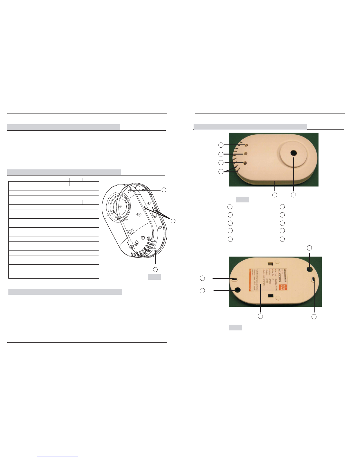
Installation CD310 should be done with 2pcs of 6mm wall plugs and 2pcs of 3.5x30mm screw. Remove
upper part of plastic cover by the help of hutch(Figure 1, point 6). Install CD310 by using installation
holes and gas absorbing holes which refers to the base of the room, smooth plane of wall.
Install wall plugs and bottom part of plastic cover. Make suitable cable connection. Place uppert part of
plastic cover; gas absorbing holes refers to the base.
After power up, push test switch and test gas detector. Pushing test switch red led on and buzzer warns
by sound.
6
6
Figure:13
At A Glance To The Detector
6
9
9
CARBON MONOXIDE DETECTOR
CD310/330/330R
CARBON MONOXIDE DETECTOR
Yellow Led
Led Display: Fault
CD310 CD330R CD330
10
Red Led- Alarm/Yellow Faulth
Test Switch
Green Led - Operating
Gas Absorbing Holes
Sound Emitting Hole
Hutch
Cable Holes
Label
Installation Holes
Power Supply Socket
Page 3
3/8
*Install a CO Alarm in all rooms where there is a fuel burning appliance
*If there is more than one appliance, but only one CO Alarm is to be installed, the following priority list
is recommended:
1.Rooms containing a flue-less or open-flued appliance
2.Rooms where occupants spend most time
3.Rooms in which the appliance is most used
4.If the dwelling is a bedsit the CO alarm should be positioned away from the appliance, but close to
the sleeping area
In an enclosed space e.g a cupboard
Where it can be obstructed
Directly above a sink
Next to a door or window
Next to an extractor fan or vent
Where dirt & dust may block the sensor
In a damp or humid location
In the immediate vicinity of a cooking appliance
CO Alarms should not be located:
6/8
In Alarm Situation
Stay calm. Do not touch any sockets or switches. Do not use any electrical devices. Do not smoke.
Turn off all gas valves.
Immediately evacuate the place, if you don’t know source of gas leakage. Do not interrupt any
electrical device for stopping alarm sound. Inform authorized firm about gas leakage.
Cautions
Do not open or make changes on detector, except making suitable cable connections. Adjustment of
detector must be done by authorized technical services. Alcohol and its’ steams, sprays, saturated
smoke, lighter gas, strong smell of cleaning chemicals confuses and giving wrong alarm by detector.
Use wet packs for cleaning outside of detector. Never use spray or chemicals. Ventilate place and do
not smell any gas leakage.
Carbon Monoxide is an invisible, odourless, tasteless and extremely toxic gas that, if
inhaled, can cause serious ill effects - justifying its name as 'The Silent Killer'. CO is readily
absorbed by haemoglobin in the blood - approximately 240 times more efficiently than
oxygen. This causes serious damage to the heart and brain from oxygen starvation.
Carbon Monoxide originates from the combustion of any fossil fuel -coal, bottled and natural
gas, paraffin, wood, petrol, diesel,charcoal etc.
All Fossil fuel burning appliances produce CO, this is normally vented through flues and
chimneys to the outside atmosphere. However, if the process is not entirely efficient, CO can
build up to dangerous levels. Examples of possible causes are:
*Poorly connected,blocked,cracked or corroded flue pipe/vent
*Back drafting
*Cracked heat exchanger on gas central heating system
*Appliances without flues
Carbon Monoxide poisoning can have a very serious, even fatal, effect on the body.
Unfortunately, most people are unaware that a relatively low level of CO exposure for a
prolonged period can have the same effect as a high level of CO exposure for a short
period. A major problem is that the symptoms of CO poisoning can easily be confused with
other common illnesses - such as cold and flu. The table details the effects of cumulative
CO exposure.
How is CO produced?
What are the main sources of CO?
What are the effects of CO poisoning?
What is CO & hy does it need to be monitored?W
The CD310/330/330R Carbon Monoxide Alarm measures the concentration of Carbon
Monoxide and sounds a loud alarm when a potentially harmful level is reached.
CO Parts Response
per million CD310 Time
30ppm 120-140 sec
50ppm 60-90 sec
100ppm 10-40 sec
300ppm 2,5 sec
Three separate indicating LED's provide visual information:
Healthy mains supply(Green)
CO level sensed/alarm status(Red)
And if a fault is detected(Yellow)
Alarm Condition
Where should CO Alarms be located?
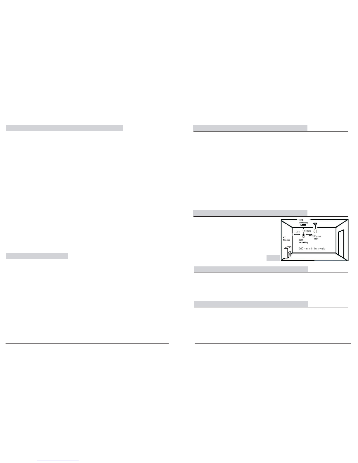
CEILING MOUNTING
Preferred position in rooms containing
A fuel burning appliance
*1-3m horizontally from the appliance
*At least 300mm from any wall and obstructions
(E.g. light fitting)
Wall Mounting Option
*1-3m horizontally from appliance
*150mm vertically down from ceiling
*Above the height of any doors or windows
Where should CO Alarms be positioned?
Figure: 3
Page 4
5/8
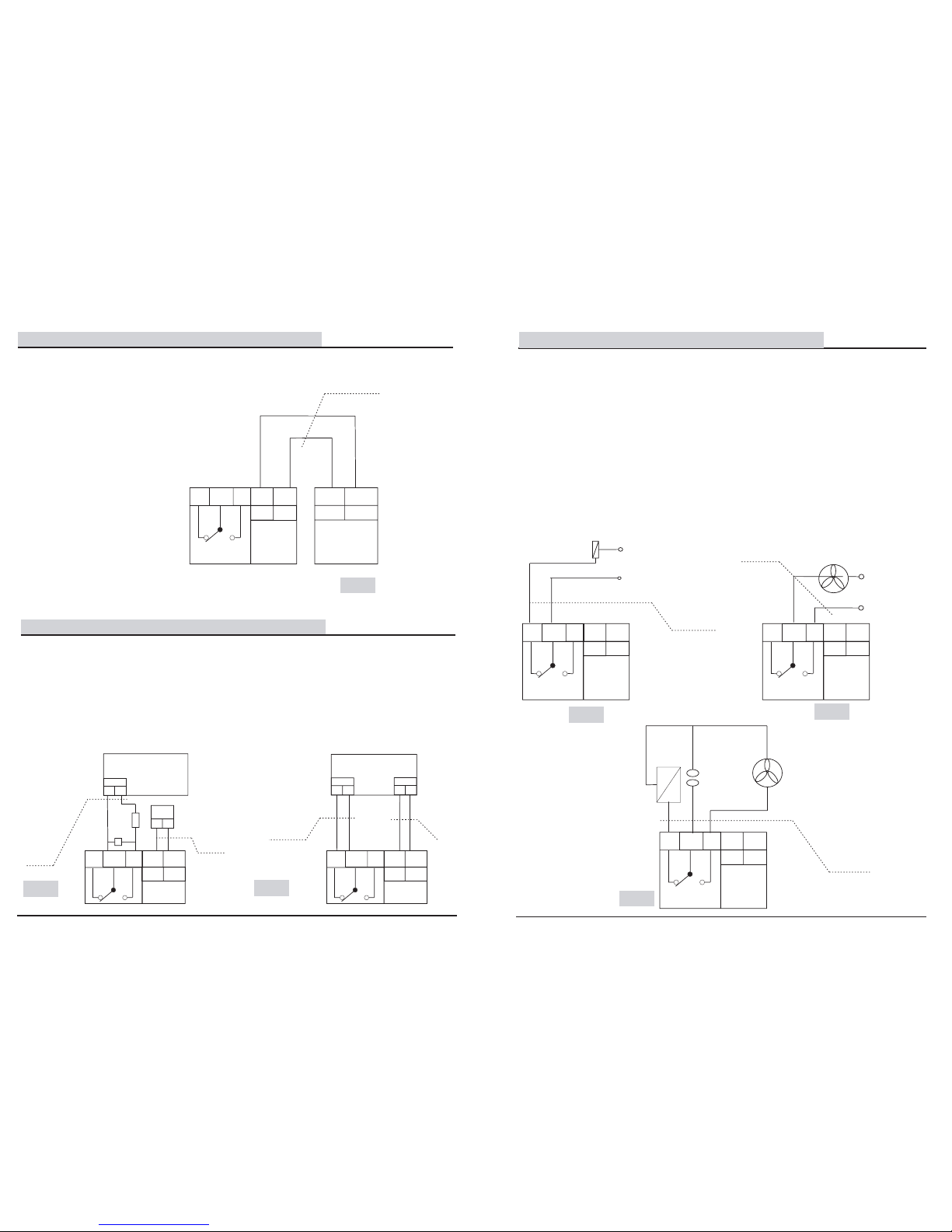
When detector , detects gas leakage ,you will be command fan or gas interrupt valve automatically,
using relay outputs. CD 310/330R has 1A total current relay for NC&NO relay outputs. Connecting
one or many equipments, not exceeding total value of 1A current. Above 1Acurrent connect suitable
contactor.Connection of automaticlly commanding equipments notr line to the detectors Com
terminal.
On the other line; Operating Operating automatically command equipment in the alarm situation,
connect detector’s NC terminal(Figure 7), interrupt operating equipment automatically connect NO
terminal(Figure 8).
According to the instructions above, operating or interrupt operating some equipments(Figure 9). On
the other hand operating equipments makes danger during gas leakage have to be considerated.
If the detector operating by connecting panel, automatic operation should be command by the
panel.
4/8
Connections
Panel Connections
Power connection of the detector, from a panelor a power supply by the double ribbed cable which has
radius of 1.5square milimeters.
Sending alarm signal to the panel, by the connection of double ribbed cable to the relay outputs.
For using relay outputs(NC&NO), read instruction manual of panel. According to the instruction manual
of panel, you may use suitable alarm Resisto(B) or end of line resistor(A), for the relay output
connections. Connection Schemas are Figure 5 and Figure 6 . For suitable resitors and connection
schemas of panel, look inside instruction manual of panel.
Relay Output Connections
12V DC
Power Supply
2x1,5mm
Figure:4
Figure 4 connection to a power supply
+
NC NOCOM
12V
0V
12V DC
+
+
-
-
0V
12V
+
FIRE ALARM PANEL
A
B
SECURITY PANEL
Figure:5
Figure:6
2x1,5mm
2x1,5mm
2x1,5mm
+
+
+
+
+
+
+
-
ZONE
+
-
ZONE
+
-
12V
+
+
+
-
12V DC
PowerSupply
+
NC NOCOM
12V
0V
12V DC
-
+
NC NOCOM
12V
0V
12V DC
-
NOTR
LINE
SELENOID
VA LV E
220 V AC
NOTR
LINE
220 V AC
FAN
NOTR
FAN
SELENOID
VA LV E
Figure:8
Figure:9
Figure: 7
2x1,5mm
2x1,5mm
2x1,5mm
+
+
+
+
+
+
+
LINE
+
NC NOCOM
12V
0V
12V DC
-
+
NC NOCOM
12V
0V
12V DC
-
+
NC NOCOM
12V
0V
12V DC
-
 Loading...