

EDPAC Close Control 6, Close Control 12, Close Control 18 Installation, Operation & Maintenance Manual
Page 1

Close Control
Small System Range
Chilled Water Units
Installation, Operation & Maintenance Manual 50/60Hz
Page 2

2
INSTALLATION OPERATION & MAINTENANCE MANUAL
Index
Description
Page
INSTALLATION
General
3
Mechanical Installation
4
Water and Drain Connections
5
General Engineering Data
6
Electrical Connections
7
OPERATION
General
EC Fan910
Heating Operation
11
Cooling Operation
11
Dehumidification Control
12
Humidification Cycle
12
PGD Details
14
Alarms
15
MAINTENANCE
General
18
Common Components
18
Electric Panel – Inspection & Functional Tests
19
Steam Humidifier Canister Cleaning & Removal
20
Fault Finding Guide
21
Monthly Maintenance Inspection Check
23
Annual Maintenance Inspection Check
24
While every precaution has been taken to ensure accuracy and completeness in this manual, EDPAC assumes no responsibility, and disclaims all liability
for damages resulting from use of this information or for any errors or omissions. Document reference E4.19-02-06-04
Page 3

3
GENERAL
On receiving the equipment it should be checked to ensure that it is complete and in perfect condition. The carrier should be notified
immediately, in writing, of any damage that might have been caused in transit.
HANDLING
Always keep the unit vertically upright and do not leave it out in the open. The unit can be moved with a pallet truck. If a forklift is
being used ensure the forks extend beyond the pallet. Care should be taken not to damage the bottom of the unit. If a crane is being
used to move the unit leave the packaging intact and place spreader bars across the top of the unit to prevent the slings causing
damage. The unit should be moved as near as possible to the installation position before removing the cardboard packing and the
pallet.
UNPACKING THE UNIT
1) Cut the three straps binding the unit taking care to avoid any backlash caused by their tightness.
2) Remove the lid.
3) The cardboard sleeve will then unravel itself revealing a plastic dust cover.
4) Remove dust cover. If it is a downflow model, to remove the front panels use the key attached to the sensor on the top of the unit.
5) Remove the two bolts securing the unit to the skid (19 mm spanner).
6) Manoeuvre the unit carefully from the pallet. If it is necessary, use rollers underneath the unit to locate it in its final position.
7) If the unit requires a plenum fix same before final positioning.
8) Ensure the unit is positioned on a level floor.
POSITIONING
Single Circuit Units.
The Modular Range is built on a level base and its positioning is most important. The unit should be firmly supported on the floor
itself or on an optional floorstand.
Ensure that the unit is level in all directions as failure to do so will result in operational problems, particularly with regards to
drainage. Care should be taken in manoeuvring the unit as the paintwork could be damaged. Use rollers where possible and apply
pressure to the bottom of the unit for final positioning. Before final positioning ensure that inaccessible panels are correctly fitted and
plenums are secured.
ATTACHING THE PLENUM
The plenum and unit are pre-drilled. At the time of installation remove the grilles from the plenum and secure the plenum internally by
means of self tapping screws provided. Also secure to the back of the unit.
AIR COOLED CONDENSERS
Locate these as close to their final position as possible before uncrating. A full set of assembly instructions are attached to the unit.
Headers and return bends are not to be used in the moving of the condenser.
When locating the condenser ensure that it is in an open area with unrestricted airflow shaded from direct sunlight.
Install in an environment free of debris to avoid the fins becoming blocked.
Ensure that some form of vibration elimination is installed between the condenser legs and the roof of the building.
Condensers are not to be ducted on either side.
Where noise is critical in relation to the condenser make ensure that this is clearly specified at the time of order.
INSTALLATION
Page 4
4
SERVICE ACCESS
Downflow Units
Service of a downflow unit can be generally completed from the front of the unit. To remove certain components from the unit it may
be easier and quicker to have side access to assist in these operations.
When positioned there should be a minimum clearance in front of the unit of 0.6m. If it is feasible, leave a distance of 0.6m at the
side of the unit. Access to the back of the unit is not necessary. It is strongly recommended to leave a distance of 0.6m at both sides of
the unit. There is a minimum distance of 150mm needed above the unit to allow removal of the filters.
Upflow Units
Unlike the downflow, side access is necessary for servicing the upflow. When installing ensure the left-hand side of the unit has access
for the purpose of servicing, especially the motor. On the small frame the motor is actually mounted 'piggy-back' on the blower and on
the mid and large frame the motor is located on the left-hand side of the blower
Access to the back of the unit is not required. It is strongly recommended to leave a distance of 0.6m at both sides of the unit. The
filters are located in the bottom front panel; a minimum distance of 1m is needed to allow the return air to enter the unit.
Space above the unit will be determined by location. If a standard plenum is being installed the overall height of the unit is extended
to 2380mm.
MECHANICAL INSTALLATION
SYSTEM APPLICATION
To achieve maximum performance and efficient energy usage following considerations should be given:
1) The room should be sealed effectively against air and vapour to minimise the loss and infiltration of uncontrolled humidity through
concrete slab, walls, ceiling, roof, doors or any other opening or aperture.
2) Room location and orientation should be considered with regard to heat load and external variables should be reduced to a
minimum.
3) The room should be kept at a positive pressure by introduction of pre-treated fresh air.
4) Low resistance to conditioned air distribution can be achieved by providing the maximum raised flooring height, minimum cable
bunching and correct position of pipework (i.e. parallel to air flow).
5) Pipework that is not isolated or is fastened inadequately can transmit vibration along its full length.
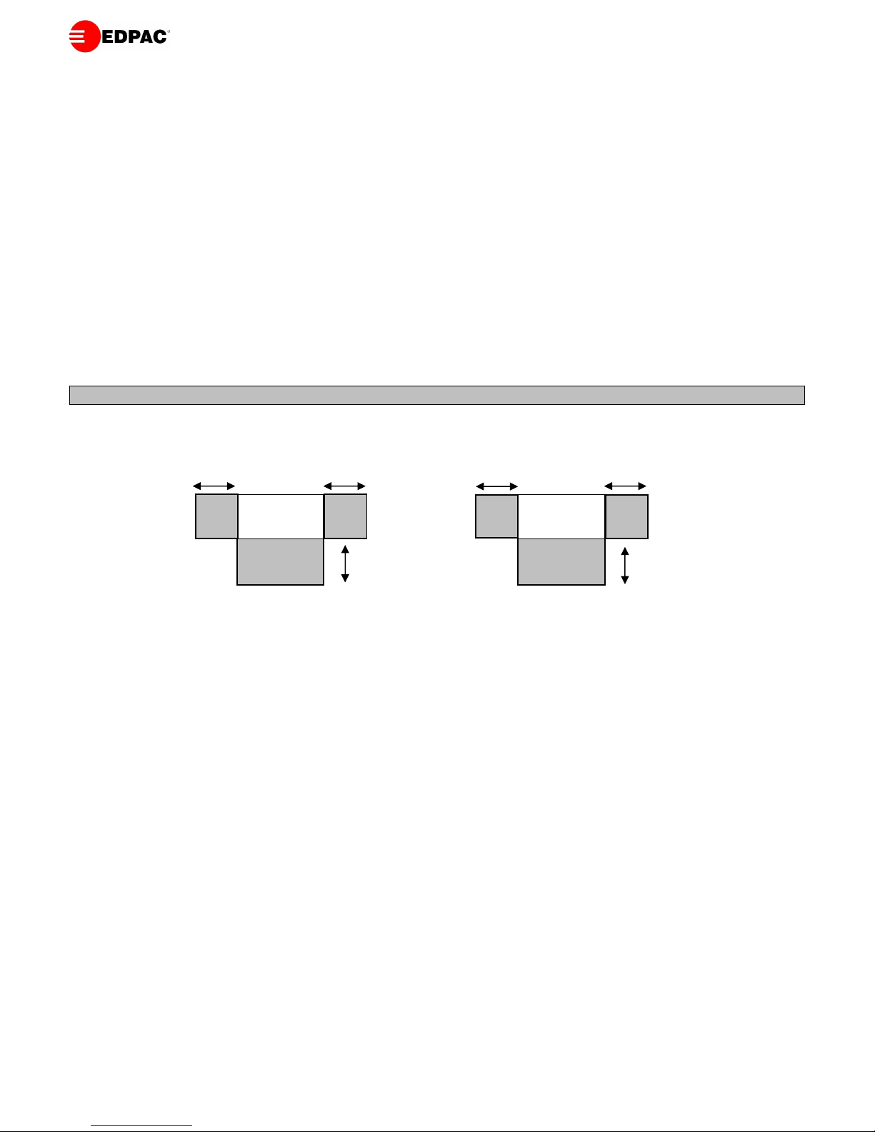
Room Unit
Downflow Small System Unit
Service Access
600
Room Unit
Upflow Small System Unit
Service Access
600
600
Page 5
5
CHILLED WATER UNITS
CHILLED WATER PIPING CONSIDERATIONS
Chilled water units are shipped with the flow and return pipes terminated with soft solder caps. The complete system is pressurised to
75psi with dry nitrogen. This pressure should be rechecked and discharged before caps are unsoldered. Supply and return pipes are
clearly marked. Check the site piping to ensure that the flow is in the proper direction.
The maximum allowable static pressure for the chilled water circuit is 1000kPa. If static pressure exceeds 1000kPa special valves
should be installed. Consideration of the minimum water temperature to be supplied from the chiller will determine if the need exists
to insulate the supply and return lines.
It is recommended that isolating valves be field fitted on both flow and return lines from the unit for isolation and maintenance
operations. Automatic air bleed valves should also be fitted in appropriate locations.
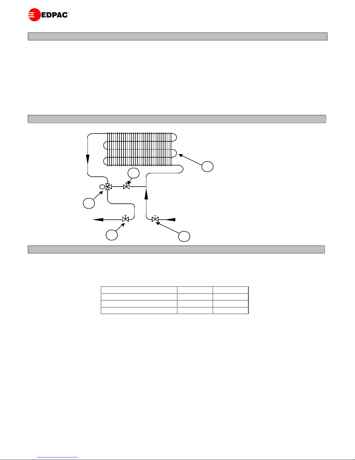
GENERAL ARRANGEMENT DRAWING
System Components
1. Evaporator Coil.
2. Balancing Valve
3. 3 Way Modulating Valve
4. Isolating Valves
Note: Item 4 is field fitted by others.
WATER AND DRAIN CONNECTIONS
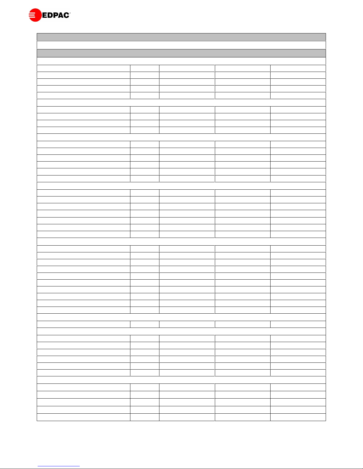
WATER SUPPLY
Water is fed from the mains supply to the humidifier inlet solenoid valve. The connection to the solenoid valve is a 3/4” male
connection. The feed water characteristics should comply with the following values:
In the case of high water pressure a pressure reducing valve calibrated to between 3 - 4 bar should be fitted. Inlet water temperature
must not exceed 50oC. It is recommended to install a shut-off valve and a mechanical filter with the wire mesh size less than 50µm.
The humidifier pan drain connection is a 22 mm female connection. The humidifier drain can be discharged into the standard drainage
system via a rubber or plastic hose suitable for temperatures up to 100oC. The hose should have a minimum internal diameter of
22mm. A trap or vertical loop should be fitted in the tubing to prevent blow back or odours and ensure that the drain has a fall of not
less than 1:50.
Note: Do not feed demineralised water into the humidifier.
CONDENSATE DRAIN
Install a drain pipe from the base of the drainpan (typically a 1" female B.S.P. fitting). Insulating this drain pipe is not necessary. It is
advised to fit a trap in this drainpipe. On a twin circuit unit there are knockouts on the side panels to route drain hoses through to a
single outlet. Copper pipe should be used for drains on units with humidifiers. If the system is equipped with a condensate pump,
install a check valve on the discharge line of the pump to prevent backfilling the pump reservoir.
Characteristic
Minimum
Maximum
Feed Water Pressure
1 bar
10 bar
Electric Conductivity at 25oC
400 µS/cm
800 µS/cm
Impurity Size
-
0.1 mm
M
1
Chilled Water Flow
Chilled Water Return
1
2
3
4
4
Page 6
6
GENERAL ENGINEERINGDATA
Model0612
18
Air Side Data
Air Volume
m3/hr
1,800
3,600
5,400
m3/s
0.5
1.0
1.5
External Static Pressure ESP
Pa7575
75
No. of Fans
No.11
1
Fan MotorkW0.55
1.10
1.50
Optional EC Plug Fan
Quantity
No.11
1
Fan Diameter
mm
450
450
450
Fan Motor
kW
1.0
1.0
1.0
Fan Absorbed Power
kW
0.3
0.5
0.9
Filter Data
Downflow Filter Size
mm
495 x 535
495 x 535
495 x 695
Downflow Filter Quantity
No.22
2
Upflow Filter Size
mm
775 x 300
775 x 300
775 x 460
Upflow Filter Quantity
No.11
1
Filter Depthmm100
100
100
Filter Efficiency
-G4G4
G4
Water Side Data
Control Valve Size
mm2025
25
Control Valve Kv
-
4.0
6.3
6.3
Chilled Water F&R Pipe Size
mm2228
28
Cooling Coil Data
Coil Face Area – DX and C. Water
m20.4
0.6
0.6
Coil Rows
No.44
4
Coil Drain Connection BSPF
inch11
1
Air Cooled Units
Discharge Line Pipe Size
mm1616
16
Liquid Line Pipe Size
mm1212
12
Condenser Conns. Inlet/Outlet 30°C
mm
22/16
22/16
28/22
Condenser Conns. Inlet/Outlet 35°C
mm
22/16
28/22
28/22
Condenser Conns. Inlet/Outlet 40°C
mm
22/16
28/22
35/28
Condenser Conns. Inlet/Outlet 45°C
mm
22/16
35/28
35/28
Condenser Conns. Inlet/Outlet 50°C
mm
28/22
35/28
35/28
Scroll Compressor – 50Hz
-
ZR34K
ZR61K
ZR81K
Scroll Compressor – 60Hz
-
ZR28K
ZR48K
ZR72K
Compressor Quantity
No.11
1
Noise Data
Free field SPL @ 3m
dBA5255
57
Optional Humidifier Data
Capacity
kg/hr22
3
Inlet Connection BSPM
inch11
1
Drain Connection BSPM
inch11
1
Water Feed Pressure
Bar
1-10
1-10
1-10
Water Feed Electrical Conductivity
μS
400 – 800
400 – 800
400 – 800
French Degrees Water Hardness
-
15-30
15-30
15-30
Optional Electric Reheat Data
Capacity - 400V/3Ph/50Hz
kW
7.5
7.5
9.6
Capacity - 220V/3Ph/60Hz
kW
7.5
7.5
9.6
Capacity - 380V/3Ph/60Hz
kW
6.8
6.8
8.7
Capacity - 460V/3Ph/60Hz
kW
10.0
10.0
12.8
No.of Stages
No.22
2
Notes
1. Indoor unit Free field SPL dBA levels are measured at 3m.
2. For correct installation pipe sizes refer to refrigerant and water pipe sizing tables.
Page 7
7
400V/3PH/50Hz
Model
61218
Controls FLA
1.0
1.0
1.0
Fans FLA
1.5
2.7
3.6
Reheat FLA
10.9
10.9
13.9
Humidifier FLA
2.2
2.2
3.2
Max Unit FLA - Cooling only
2.5
3.7
4.6
Max Fuse FLA
10.0
10.0
10.0
Max Unit FLA - Cooling & Dehumidification
13.4
14.6
18.5
Max Fuse FLA
20.0
20.0
25.0
Max Unit FLA - Heating and Humidification
15.6
16.8
21.7
Max Fuse FLA
20.0
25.0
30.0
220V/3PH/60Hz
Model
61218
Controls FLA
1.0
1.0
1.0
Fans FLA
2.7
4.9
6.6
Reheat FLA
19.8
19.8
25.3
Humidifier FLA
4.0
4.0
5.8
Max Unit FLA - Cooling only
3.7
5.9
7.6
Max Fuse FLA
10.0
15.0
20.0
Max Unit FLA - Cooling & Dehumidification
23.5
25.7
32.9
Max Fuse FLA
30.0
35.0
45.0
Max Unit FLA - Heating and Humidification
27.5
29.7
38.7
Max Fuse FLA
35.0
40.0
50.0
Notes:
1. FLA = Full Load Amps.
2. Unit maximum FLA is the total of the components, which operate during maximum electrical load conditions.
3. Max FLA of Cooling only unit : FLA = Controls + Fans
4. Max FLA of unit with reheat only in dehumidification : FLA = Controls + Fans + Reheat.
5. Max FLA of units with heating & humidifiers : FLA = Controls + Fans + Reheat + Humidifier.
6. Max Fuse is the recommended value of the unit overcurrent protection device.
ELECTRICAL DETAILS – CHILLED WATER UNITS
Page 8
8
380V/3PH/60Hz
Model
61218
Controls FLA
1.0
1.0
1.0
Fans FLA
1.6
2.9
3.8
Reheat FLA
10.3
10.3
13.2
Humidifier FLA
2.3
2.3
3.4
Max Unit FLA - Cooling only
2.6
3.9
4.8
Max Fuse FLA
10.0
10.0
10.0
Max Unit FLA - Cooling & Dehumidification
12.9
14.2
18.0
Max Fuse FLA
15.0
20.0
25.0
Max Unit FLA - Heating and Humidification
15.2
16.5
22.8
Max Fuse FLA
20.0
25.0
30.0
460V/3PH/60Hz
Model
61218
Controls FLA
1.0
1.0
1.0
Fans FLA
1.3
2.3
3.1
Reheat FLA
12.6
12.6
16.1
Humidifier FLA
1.9
1.9
2.8
Max Unit FLA - Cooling only
2.3
3.3
4.1
Max Fuse FLA
10.0
10.0
10.0
Max Unit FLA - Cooling & Dehumidification
14.9
15.9
20.2
Max Fuse FLA
20.0
20.0
25.0
Max Unit FLA - Heating and Humidification
16.8
19.2
23.0
Max Fuse FLA
20.0
25.0
30.0
Notes:
1. FLA = Full Load Amps.
2. Unit maximum FLA is the total of the components, which operate during maximum electrical load conditions.
3. Max FLA of Cooling only unit : FLA = Controls + Fans
4. Max FLA of unit with reheat only in dehumidification : FLA = Controls + Fans + Reheat.
5. Max FLA of units with heating & humidifiers : FLA = Controls + Fans + Reheat + Humidifier.
6. Max Fuse is the recommended value of the unit overcurrent protection device.
ELECTRICAL DETAILS – CHILLED WATER UNITS
Page 9

9
OPERATION
GENERAL
MICROPROCESSOR CONTROLS
All Units shall be fitted as standard with the latest Delta range of DIN rail mounted Microprocessor Controls. The Control
System utilises a main Microprocessor Interface Board equipped with a set of terminals necessary to connect the Board to the
controlled devices.All software is permanently stored in flash RAM and is therefore protected even in the event of a power
failure. Unit software is uploaded to the Microprocessor using a RAM key. On multi unit sites, this quickens unit
commissioning. The software can also easily be changed or upgraded on site by qualified service personnel.
Note:
For more detailed information refer to Detailed Controls Manuals.
1)
DELTA
RANGE MICROPROCESSOR CONTROLLER SYSTEM PROGRAMMING MANUAL.
GENERAL SYSTEM OPERATION
Unit operation is completely automatic. The sequence below explains how the unit operates:
The air, drawn in by the fan(s), enters the unit through top of the unit or the inlet grille.
The air is immediately filtered.
The temperature & relative humidity sensor verifies the condition of the inlet air and relays this to the microprocessor
controller.
The controller compares this information to the set point and proportional band values programmed into its memory. it
then commands the air conditioner to treat the air as appropriate.
CUSTOMER CONNECTIONS
Power cables to the load break switch should be sized in compliance with local codes (see electrical data for permissible fuse
size). Power cables required are 3 phase and a neutral (2.5mm minimum size neutral) and appropriately sized ground. The
ground connection is vital. External device control connections to the control section are as follows:
a) Connections to the condenser/dry cooler are is via terminals 27 & 28.
b) Connection to the remote shutdown feature is via terminals 15 & 16. Normally Closed N/C Unit On, Normally Open N/O
Unit Off by Remote. A relay is required for this option.
c) Connections for the external alarm relay's are via terminals 18, 19 & 20, (250 VAC rated - 10 Amps). Volt Free Contacts.
d) Externally required A.C. voltage supplies are not to be taken from the unit, interface relays are to be utilised for these
applications.
INITIAL START UP
a) On initial start-up the controller will display the following message:
b) After a 5 second delay the controller will display the following:
The unit is now ready for operation.
SYSTEM BOOT
PLEASE WAIT
13:58 12/02/97 MOI
Temperature: 23.4 deg.C
Humidity: 37.7 RH%
UNIT ON
Page 10

10
AIRFLOW OPERATION
a) When the electrical power has been energised for at least 3 hours, the unit may be energised by pressing the "On/Off" key
on the keypad. The fan contactor KM1 (& KM2-Duplex) will energise establishing airflow.
POWER FAILURE, INTERRUPTION OR SYSTEM RESET
a) Should a `brownout' (where voltage is low enough to cause the electronics to fail) or electrical power failure occur, the
controller will be alerted as the voltage begins to drop. It will then de-energise all contactors. During power failure all data
entered through the keypad will be held in a memory back-up which is supported by an Eprom. The Eprom will retain data
indefinitely without external power.
b) If a unit is in the "RUN" mode when a power failure occurs, then, upon power restoration the unit will automatically
commence "RUN" operation. The settle timer will count down to zero and at zero the unit will then continue as outlined in
the Airflow, Temperature Control and Humidity Control sections.
EC FAN OPERATION
GENERAL
The EC plug fan is a backward curved fan with an integrated EC electrically commutated motor which is controlled directly
from the microprocessor using a 0-10V output. Options on setup are:
Strategy 1: Fixed speed
Strategy 2: Track temperature band
Strategy 3: Maintain pressure setpoint
Strategy 4: Control from BMS
Strategy 5: Maintain airflow setpoint
Dehumidification control mode
FIXED SPEED
A fixed 0-10V signal is set through the user display to operate the fan at a constant speed.
TRACK TEMPERATURE BAND
The unit is set up to track the heating and cooling bands with set voltage limits. Max voltage / fan air volume is at set point plus
control band & min voltage / fan air volume at set point
Max voltage / air volume is typically design air volume and min air volume is typically around 60% for chilled water units.
Minimum value needs to insure that there are no hot spots due to lack of airflow and that there is no loss of sensible cooling
capacity to latent cooling capacity at the cooling coil.
MAINTAIN PRESSURE SETPOINT
The microprocessor reads the underfloor pressure via a pressure transducer. The fan speed is then controlled to maintain a
fixed underfloor pressure at all times. Pressure setpoint and min & max voltages are input through the user display. A reading
of the underfloor pressure can also be viewed.
CONTROL FROM BMS
The speed of the fan can be controlled directly from a BMS if one of the optional BMS interface cards are installed in the unit.
The BMS writes a value of between 0 & 100.0% to an analog BMS address. The fan then operates to this speed. Min and max
voltage can be input through the user display to insure the fan operates within acceptable limits.
MAINTAIN AIRFLOW SETPOINT
The microprocessor calculates the airflow through the unit with the use of a pressure transducer and a special inlet ring across
one of the fans designed for measuring airflow. PID control in then utilized to control the speed of the fans to insure a steady
supply air volume. Airflow setpoint and min & max voltages are input through the user display. A reading of the total airflow
through the unit can also be viewed.
DEHUMIDIFICATION CONTROL MODE
Unit set up to give a reduced fan air volume in dehumidification mode to conserve energy in dehumidification while quickly
achieving the dehumidification effect at the cooling coil. This output voltage is again user selectable.
Page 11

11
GENERAL
This can take one of two forms:
Electrical heating: The electric elements heat the air passing over them. Heating is supplied by 3 elements configured to
support 2 stages of heating. Airflow has to be established before the elements are energised. The heaters are protected
by a manual reset thermostats. This thermostat is a capillary type stat positioned across the coil near the elements.
Hot Water Heating (optional): If hot water is available this flows through the hot water coil thus heating the air passing
over it. The hot water flow is controlled by an on-off (2 or 3-way) valve.
On a Duplex unit the heating operation is carried out in the master module only.
NOTE: Heating and cooling cannot occur simultaneously.
ELECTRIC HEATING
CAUTION: When commissioning the heater stage, be aware that the electric heater elements may at first give off smoke and
may cause smoke detectors on site to alarm, e.g. Halon System.
ELECTRIC HEATER PROTECTION & ALARMS
a) The electric heaters are protected by one high temperature stats (RS1) which is fitted in the heater termination box.
b) RS1 is a capillary type temperature stat. This capillary wrapped around the electric heater elements. If the temperature of
the heater elements rises above 145 Deg. C the stat contacts will open and electric heating will be terminated.
c) When the return air temperature drops sufficiently RS1 can be manually reset. Electric heating will continue as normal.
Hot Water Reheat
a) Hot Water Heating occurs when the return air temperature falls below the return air temperature setpoint. The solenoid
valve or modulating valve will energise.
b) As the return air temperature rises above the return air setpoint the controller will cancel the heating process by de-
energising the solenoid valve or modulating valve.
Note: Heating can occur when compressor 1 is operating in the dehumidification mode and the return air temperature is below
the return air temperature setpoint by the appropriate amount.
COOLING OPERATION
GENERAL
Note 1: Cooling can only occur when airflow is established.
Note 2: Modulating valves are fitted as standard on all units.
SINGLE CIRCUIT COOLING
MODULATING VALVES.
a) A rise in return air temperature above the return air setpoint (default 22.0°C) will prompt the controller to call for cooling.
b) The chilled water modulating control valve will energise. The modulating valve will modulate to balance the load as the
temperature increases.
c) As the return air temperature falls the controller will calculate the optimum use of the modulating valve.
d) As the return air temperature drops to above the return air setpoint, the controller will modulate the valve until completely
closed.
TWIN CIRCUIT COOLING
MODULATING VALVES.
a) A rise in return air temperature (default 0.7°C) above the return air setpoint (default 22.0°C) will prompt the controller to
call for cooling.
b) The chilled water modulating control valves will energise. The modulating valves will modulate to balance the load as
temperature increases.
c) As the return air temperature falls the controller will calculate the optimum use of the modulating valves.
d) As the return air temperature drops to (default 0.6°C) above the return air setpoint, the controller de-energise the
modulating valves.
HEATING OPERATION
Page 12

12
DEHUMIDIFICATION CONTROL
a) With the airflow established, an increase in return air relative humidity above the return air relative humidity setpoint
(default 50.0%) will prompt the controller to call for dehumidification.
b) The chilled water proportional valve opens 100% to produce 100% cooling.
b) Should the return air relative humidity drop the return air relative humidity setpoint, the controller will cancel the
dehumidification stage.
c) Heating can only occur when the cooling valve is operating in the dehumidification mode and the return air temperature is
below the return air temperature setpoint by the appropriate amount. Cooling/Heating take priority control over
Dehumidification
DEHUMIDIFICATION OVERRIDE
During dehumidification, should the return air temperature drop below temperature setpoints then the controller will override
the call for dehumidification until the heaters cause the return air temperature to be within setpoint tolerances and will then
re-energise the dehumidification stage if it is required.
HUMIDIFICATION
When a call for humidification exists, the microprocessor controller sends a 24V ac signal to the humidifier contactor
supplying power to the boiler cylinder electrodes. The electric power dissipated in the boiler is kept constant by measuring the
amount of current flow on phase (L3) via a current transformer.
As evaporation proceeds, the controller opens the fill valve allowing water to enter the cylinder via a filter and a capacity
regulator to the filling cup, and from there, by gravity, to the boiler. When the water level is so high that it touches the
electrodes at the top of the boiler, the fill valve is closed and the excess water is drained through overflow tube.
The drain valve opens periodically to drain water and reduce salt concentration in the boiler. It is also used to drain the
humidifier completely under alarm conditions.
SYSTEM OPERATION
The humidifier interface PCB maintains the electric current dissipated in the boiler at the programmed set point. The PCB
therefore changes the immersion level of the electrodes by adding or draining water from the boiler through the respective
valves. The operating current may be programmed on the front display panel between 30% and 100% of the rated value of the
equipment. The functions of the equipment are described below:
FILL VALVE - maintains absorbed current between -10% and +10% of set point (percentages refer to rated current) by opening
or closing respectively, with the first or second thresholds. The fill valve is automatically closed when:
The drain valve is opened
The free surface of the water reaches the level electrodes
The system is in a state of alarm
DRAIN VALVE - this is opened when:
The absorbed electrical current reaches set point +30% (it closes as soon as current falls set point +10%)
The washing cycle (initial or periodic) is activated
The system is in a state of alarm
TOP LEVEL ELECTRODES - these prevent water overflowing from the boiler. When they are covered with water for approx.
three seconds the valve is closed. After the level electrodes have been out of water for approx. 25 seconds, the fill valve opens
again. The level electrodes also control topping-up when absorbed current does not reach the programmed threshold because:
The water conductivity is too low
The electrodes are partially or totally encrusted
WASHING CYCLE - this prevents excessive salt build-up inside the boiler. It is activated as follows:
At regular intervals, programmable according to the size of the equipment on the basis of cumulative time of
humidification, memorised while the equipment is supplied with power
Page 13

13
ALARM CONDITION
- The red ALARM button on the front display panel lights up, the drain valve opens and electrical supply to the boiler is cut off
when:
Absorbed current exceeds 1.8 times the rated current (generally due to the fill valve overload)
The valve remains open for more than 10 minutes without the threshold of current set point +10% being reached and
without the level electrodes intervening (e.g., due to failure in the water supply, blocked intake filter, defective fill valve,
power probe current transformer, contactor, blown fuses, encrusted electrodes, etc.)
Page 14

14
PGD DISPLAY
Turning the unit On/Off : Pressing the “ ESC” & the “ Enter / Return” arrow buttons together
turns on and off the unit at the display. Pressing the up arrow button followed by the “ Enter /
Return” arrow button also turns unit on/off. Follow on screen instruction.
Alarm button: By pressing this button you can display the alarm that has occurred & reset it manually. When the red
led indicator lights up, at least one alarm condition has occurred. If there are multiple alarms then using the arrow “
up ” & “ down ” buttons lets you scroll through them.
Up arrow button: Displays the program windows and allows the user to set the value of the control parameter
Down arrow button: Displays the program windows and allows the user to set the value of the control parameter. In
default menu, pressing down arrow button displays unit operating mode.
Enter / Return arrow button: Confirms the set data.
Escape button: By pressing this button, you go back one level from where you are.
Program button: By pressing this button, you get a range of sub-menu’s.
+
Page 15

15
ALARMS
The following alarms can be activated in an alarm condition & displayed on the display screen. All alarms can be set as serious
or non-serious through the keypad
ALARM LIST
AL 01
Compressor 1 HP / Thermal Overload
AL 02
Compressor 2 HP / Thermal Overload
AL 03
Compressor 1 LP
AL 04
Compressor 2 LP
AL 05
Air Flow Alarm (Serious Alarm)
AL 06
Air Flow Alarm – Slave
AL 07
Alarm Electric Reheat High Temp Trip
AL 08
Condensate Pump / High Water Level
AL 09
Smoke/Fire (Serious Alarm)
AL 10
Alarm Air Filter
AL 11
High Temperature Alarm
AL 12
Low Temperature Alarm
AL 13
High Humidity Alarm
AL 14
Low Humidity Alarm
AL 15
High Entering Water Temperature
AL 16
Low Entering Water Temperature
AL 17
Compressor 1 Run Hours
AL 18
Compressor 2 Run Hours
AL 19
Fan Run Hours
AL 20
Return Air Temperature Probe Fault Or Offline
AL 21
Entering Water Temperature Probe Fault Or Offline
AL 22
External Air Temperature Probe Fault Or Offline
AL 23
Supply Air Temperature Probe Fault Or Offline
AL 24
Return Air Humidity Probe Fault Or Offline
AL 25
Leaving Water Temperature Probe Fault Or Offline
AL 26
High Leaving Water Temperature
AL 27
Low Leaving Water Temperature
AL 28
High Current Into Humidifier
AL 29
Lack Of Water Into Humidifier
AL 30
Lack Of Current Into Humidifier
AL 31
Alarm Clock
AL 32
Spare / Custom
AL 33
Spare / Custom
AL 34
Spare / Custom
AL 35
Water Under Floor
AL 36
Loss of Water Flow Alarm
Default List: Actual Alarms Model Dependant
Page 16

16
ALARMS
Default List: Actual Alarms Model Dependant
AL 37
Alarms Probe B00 Air pressure fault or disconnected
AL 38
Alarms Probe B00 fault Head press. circuit 1
AL 39
Alarms Probe B00 fault Head press. circuit 2
AL 40
Desiccant Dryer Alarm
AL 41
Alarm clock
AL 42
Permanent memory Read/Write error Contact factory
AL 43
EC Fan Fault or Offline
AL 44
Alarms EVO n1 - EEV Motor Error
AL 45
Alarms EVO n1 - MOP (high temperature of evaporation)
AL 46
Alarms EVO n1 - LOP (low temperature of evaporation)
AL 47
Alarms EVO n1 - Low superheat alarm
AL 48
Alarms EVO n1 - Low suction temperature
AL 49
Alarms EVO n1 - High condensing temperature
AL 50
Alarms EVO n1 - EEPROM error alarm
AL 51
Alarms EVO n1 - EEV probe S1 fault
AL 52
Alarms EVO n1 - EEV probe S2 fault
AL 53
Alarms EVO n1 - EEV probe S3 fault
AL 54
Alarms EVO n1 - EEV probe S4 fault
AL 55
Alarms EVO n1 - EEV driver offline
AL 56
Alarms EVO n1 - EEV driver battery discharged
AL 57
Alarms EVO n2 - EEV Motor Error
AL 58
Alarms EVO n2 - MOP (high temperature of evaporation)
AL 59
Alarms EVO n2 - LOP (low temperature of evaporation)
AL60
Alarms EVO n2 - Low superheat alarm
AL 61
Alarms EVO n2 - Low suction temperature
AL 62
Alarms EVO n2 - High condensing temperature
AL 63
Alarms EVO n2 - EEPROM error alarm
AL 64
Alarms EVO n2 - EEV probe S1 fault
AL 65
Alarms EVO n2 - EEV probe S2 fault
AL 66
Alarms EVO n2 - EEV probe S3 fault
AL 67
Alarms EVO n2 - EEV probe S4 fault
AL 68
Alarms EVO n2 - EEV driver offline
AL 69
Alarms EVO n2 - EEV driver battery discharged
AL 70
Alarm Compressor 1 VSD
Page 17

17
ALARMS
Default List: Actual Alarms Model Dependant
AL 71
Alarm Compressor 2 VSD
AL 72
Alarms Probe B00 External humidity fault
AL 73
Alarm External smoke alarm (Freecooling disabled)
AL 74
Alarm Ziehl-Abegg fan n1
AL 75
Warning Ziehl-Abegg fan n1
AL 76
Alarm Ziehl-Abegg fan n1 Offline
AL 77
Alarm Ziehl-Abegg fan n2
AL 78
Warning Ziehl-Abegg fan n2
AL 79
Alarm Ziehl-Abegg fan n2 Offline
AL 80
Alarm Ziehl-Abegg fan n3
AL 81
Warning Ziehl-Abegg fan n3
AL 82
Alarm Ziehl-Abegg fan n3 Offline
AL 83
Alarm Ziehl-Abegg fan n4
AL 84
Warning Ziehl-Abegg fan n4
AL 85
Alarm Ziehl-Abegg fan n4 Offline
AL 86
Alarm Ebmpapst fan n1
AL 87
Warning Ebmpapst fan n1
AL 88
Alarm Ebmpapst fan n1 Offline
AL 89
Alarm Ebmpapst fan n2
AL 90
Warning Ebmpapst fan n2
AL 91
Alarm Ebmpapst fan n2 Offline
AL 92
Alarm Ebmpapst fan n3
AL 93
Warning Ebmpapst fan n3
AL 94
Alarm Ebmpapst fan n3 Offline
AL 95
Alarm Ebmpapst fan n4
AL 96
Warning Ebmpapst fan n4
AL 97
Alarm Ebmpapst fan n4 Offline
AL 98
Analog outputs incorrectly configured check unit config.
AL 99
Alarm Refrigerant leak
AL 100
Low pressure circuit 1 (transducer)
AL 101
Low pressure circuit 2 (transducer)
AL 102
Phase rotation alarm
AL 103
High pressure prevent active. Compressor capacity reduced
Page 18

18
MAINTENANCE
GENERAL
CHECKLIST
The following should be incorporated in a planned maintenance schedule to ensure that the equipment is well maintained. In all
cases the various sections of the equipment should be examined and any defects logged for replacement/repair. For
performance analysis a detailed service/maintenance log book should be kept outlining problems encountered and defects
found during routine maintenance. Examples can be found at the end of this section.
GENERAL COMMON COMPONENTS
CABINET AND FRAME - EXAMINE
1) Examine the cabinet exterior for any obvious defects or damage and repair as necessary.
2) Remove the front, side and rear panels and examine the cabinet interior for signs of damage or corrosion. Repair any
damage found and restore the surface finish where corrosion has occurred.
3) Refit the front, side and rear panels and restore the electrical supply to the unit.
4) Record and report any defects found during the inspection.
DRIVE PACKAGE
1) Remove the unit front panels and inspect the fan motor for any loose electrical connections and retighten as necessary.
2) Inspect the fan impellers and remove any debris.
3) Check that the fan impellers are securely mounted on the fan shaft. Rotate the impellers and ensure freedom of movement.
4) Inspect the bearings for signs of wear. If any excessive movement is noticed the bearings must be renewed.
5) Check the drive belts monthly for signs of wear and proper tension. Pressing on the belts midway between the sheave and
pulley should produce approx. 12.5mm of movement. Belts that are too tight can cause excessive bearing wear.
DRIVE BELT RE-TENSIONING
1) Correctly tension the belts by adjusting the fan motor slide base as necessary.
2) After adjusting or renewing the belts, always check that the motor mounts are tight. Loose mounts will produce vibration
that may damage the unit.
Note: If belts appear cracked or worn, they should be renewed with matched belts (identically sized). On units with twin belt
drives both belts should be renewed at the same time. With proper care, belts should provide a long service life.
AIRFLOW SWITCH
1) Open the unit front panel and inspect the airflow switch located below the electric panel for any loose electrical connections
and retighten as necessary.
2) Examine the pressure sensing tube between the switch and the fan casing for defects, damage and loose connections.
Renew the tube if necessary.
3) Refit the unit front panel and restore the electrical supply to the unit.
4) Record and report any defects found during the inspection.
SAFETY NOTE
This equipment is designed for safe operation provided it is installed, maintained and serviced in
accordance with the guidelines laid down in this section of the manual. They should therefore be studied
in advance by any person wishing to work on the equipment
The equipment contains electrical components at high voltage. The main power isolation switch should
therefore be opened before access is gained to the equipment
Care should be taken to avoid hands and clothing becoming entangled in the rotating parts.
Care should be taken when working near the steam outlet pipe. This can remain hot for some time after
the unit is shut down.
Any service and maintenance operations requiring access to the inside of the equipment while in
operation should be carried out by an appropriately qualified or experienced person who is fully aware of
the potential dangers and precautions to be taken.
Page 19

19
AIR FILTERS
To maintain efficient operation, the air filters should be checked monthly and renewed as required. Because renewal intervals
may vary with environmental conditions and filter type, each unit is equipped with a filter clog switch which warnsof restricted
air flow through the filter compartment by activating the 'Change Filter' alarm.
1) On downflow models the filters can be removed from the top of the unit, whereas on upflow units the bottom front panel
contains the filters.
2) Fit new filters, refit the unit front panel on upflow units and restore the power supply.
STEAM GENERATING HUMIDIFIER
Remove the unit front panels and examine the humidifier for any loose electrical connections. Retighten any loose connections.
Examine all pipes and connections for defects, damage and security of attachment.
Ensure that the steam generating canister is properly secured to the unit frame. Refit the unit front and side panels and restore
the electrical supply to the unit. Record and report any defects found during the inspection.
CHILLED WATER COIL
1) Remove the unit front panels and inspect the coil for defects, damage or corrosion.
2) Check that the coil fins are in good condition. If they are found to be bent, they should be carefully straightened using a
proprietary fin comb.
3) Inspect the pipework connections for any signs of leaks.
4) Refit the front panels and restore electrical supply to the unit.
5) Record and report any defects found during the inspection.
CHILLED WATER VALVES
1) Remove the unit front panels.
2) Visually inspect the valve(s) for damage and ensure that the connections are not leaking.
3) Ensure that the valve(s) are securely mounted in position.
4) Ensure that the actuator(s) are securely fitted to the valve body.
5) Refit the unit front panels and restore the electrical supply to the unit.
6) Record and report any defects found during the inspection
ELECTRICAL PANEL – INSPECTION AND FUNCTIONAL CHECKS
Open the unit front, inspect the electric panel for any damage or loose electrical connections and re-tighten as necessary.
Note: -The functioning of all control circuits can be tested by actuating each of the main functions, by adjusting the set points.
COOLING FUNCTIONAL TEST
Select a set point for a temperature of 6oC below room temperature.
a) A call for cooling should be observed.
b) The chilled water valve should open, and the equipment should begin to cool.
c) A high temperature alarm may enunciate. Disregard it.
Return the set point to the room temperature.
REHEAT FUNCTIONAL TEST
Select a temperature set point for 6oC above the room temperature.
a) A call for heating should be observed.
b) Both heating contactors should energise, and the heating elements should begin to heat.
c) Disregard the low temperature alarm.
Return the set point to the desired temperature.
HUMIDIFICATION FUNCTIONAL CHECK
Set the humidification to 10%RH above the room humidity reading.
a) For a steam generating humidifier, you will immediately hear clicks as it energises. After a short delay, the canister will fill
with water. The water will heat and steam will be produced.
Return the humidity setting to the desired room relative humidity setting.
Page 20

20
DEHUMIDIFICATION FUNCTIONAL CHECK
Set the humidification setpoint to 10%RH below the room humidity reading. Make sure that the temperature set point is at or
above room temperature.
a) The chilled water valve should open, and the system should begin to cool/dehumidify.
Return the humidity setting to the desired room relative humidity setting.
NOTE: - IN CHILLED WATER SYSTEMS THE PROPORTIONAL VALVE OPENS 100%.
THE BASIC CONTROL CHECKS ARE NOW COMPLETED.
1) Replace the unit front panels and restore the electrical supply to the unit.
2) Record and report any defects found during the inspection.
STEAM GENERATINGHUMIDIFIER – CLEANINGAND RENEWAL
NOTE: REGULAR MAINTENANCE IS LIMITED TO DESCALING OR RENEWING THE BOILER. THIS IS NECESSARY WHEN SCALE ON
THE ACTIVE SURFACES OF THE ELECTRODES PREVENTS SUFFICIENT PASSAGE OF ELECTRICAL CURRENT.
1) Drain the water completely. (See Controls Manual for
details on drain procedure).
2) Disconnect the power supply to the equipment.
3) Unscrew the steam pipe from the boiler.
4) Disconnect the wiring to the main electrodes and the
level electrodes.
5) Unhook the holding spring and unscrew the humidifier
bottle by rotating it anti-clockwise on its axis.
6) Remove the bottle.
NOTE: - THE BOILER MAY GENERALLY BE USED AGAIN
AFTER DESCALING.
7) Unscrew the ring nut and extract the bottom filter.
Remove any scale and deposits under a jet of water
and clean the grids mechanically or chemically with a
commercially available cleaner.
NOTE: - WHEN ELECTRODE WEAR IS SUCH THAT
REGENERATION IS INSUFFICIENT, THE BOILER MUST BE
RENEWED.
8) Reassemble the boiler in the reverse sequence after
checking and if necessary, renewing the washer
between the threaded connection and the discharge
outlet.
In the case of serviceable humidifiers the bottle can be dismantled and thoroughly cleaned.
Page 21

21
SYMPTOM
POSSIBLE CAUSE
REMEDY
No Power
(Green On/Off control button not lit)
No power to the unit electric panel
Check that the electrical power source is
live and the main disconnect switch is
closed
No power to the control circuit
1) Check that the control circuit breaker is
closed
2) Check the 24V secondary fuse
THE UNIT DOES NOT OPERATE
The display does not operate the unit
1) Check the display connection.
2) Check the processor connections
3) Refer to the unit electrical schematic and
user control manual
ROOM TEMPERATURE TOO HIGH
Unit high Temperature Alarm
1) Controls not properly set
Check the room temperature setpoint Refer to User Control Manual
2) Lack of airflow
See “LACK OF AIRFLOW” section
3) The chilled water valve does not
work when required by the controller
Check linkage for adjustment and ensure
that it is tight on the valve.
If the valve still does not open, even though
voltage is present, then renew the valve
motor.
4) The control system does not
operate properly
See “User Control Manual”. Check that the
display and processor and/or the sensor
function properly
5) Heat load higher than expected
Check the room heat load
Check the condition and volume of fresh air
make-up
Check the quantity of infiltration of external
air
ROOM TEMPERATURE TOO LOW
Unit High Temperature Alarm
1) Controls not properly set
Check the room temperature setpoint -
Refer to User Control Manual
2) The heater does not work properly
(if fitted)
1) Check the heating elements
2) Check the electric heater MCB
3) In the case if electric heater alarm,
eliminate the cause and re-set the safety
thermostat
5) The control system does not
operate properly
See “User Control Manual”. Check that the
display and processor and/or the sensor
function properly
6) Thermal losses higher than
expected
Check the room heat loss calculations,
Check the quantity of infiltration of external
air
ROOM RELATIVE HUMIDITY TOO HIGH
Controller high humidity alarm
1) Controls not properly set
Check the room humidity setpoint - Refer to
User Control Manual
2) Latent load higher than expected
Check the room latent load, check the
quantity of infiltration of external air
3) The chilled water valve does not
work in the dehumidification mode
Check linkage for adjustment and ensure
that it is tight on the valve.
If the valve still does not open, even though
voltage is present, then renew the valve
motor.
4) The control system is not
functioning properly
See “User Control Manual”. Check that the
display and/or the sensor are functioning
properly
ROOM RELATIVE HUMIDITY TOO LOW
Controller low humidity alarm
1) Controls not properly set
Check the room humidity setpoint - Refer to
User Control Manual
2) Latent load higher than expected
Check the room latent load, check the
quantity of infiltration of external air
3) The humidifier does not function
properly
Check the make-up water pressure
Check the humidifier and cylinder
FAULT FINDING GUIDE
Page 22

22
SYMPTOM
POSSIBLE CAUSE
REMEDY
LACK OF AIRFLOW
Loss of Airflow alarm
1) No power to the fan motor
Check the fan motor MCB and electric
supply at the motor box terminals
2) Clogged filters
Replace the filters
3) The airflow is obstructed
check fan inlets, air intake and supply paths
are free
4) the main fan overload has tripped
check the electrical resistance of the motor
windings. After re-set, measure the supply
voltage and current drawn.
5) The pressure drop in the air
distribution system (ducts, ceilings,
flooring, plenum, grilles, etc.) is too
high
1) Check the design and sizing of the air
distribution system
THE HEATER SAFETY THERMOSTAT
CUTS OUT
1) Lack of airflow
See LACK OF AIR FLOW
(Heater trip alarm)
2) thermostat faulty connection wire
Check the electrical continuity of the safety
thermostat connection to the controller
3) Defective thermostat
replace the heater safety thermostat
Page 23

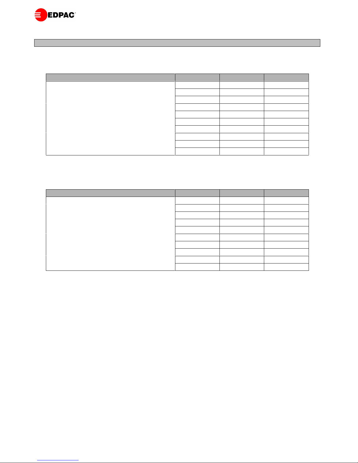
23
MONTHLY MAINTENANCE INSPECTION CHECK
MODEL NUMBER
SERIAL NUMBER
DATE
INSPECTOR
FILTERS
STEAM HUMIDIFIER
Check filter switch (if fitted)
Check humidifier bottle for deposits
Inspect filters and replace if necessary
Check condition of steam hoses
DRIVE PACKAGE
CHILLED WATER SECTION
Blower impellers moving freely and free of debris
Check that the valve motor is correctly secured
Check belt tension and condition
Check pipework is secure.
Bearings in good condition
Check joints for leaks
Check airflow switch setting and operation.
Check coil for damage
Check pulley and sheave are secure
Inspect blower anti-vibration mounts
GENERAL NOTES AND OBSERVATIONS
Page 24

24
ANNUAL MAINTENANCE INSPECTION CHECK
MODEL NUMBER
SERIAL NUMBER
DATE
INSPECTOR
FILTERS
Check filter switch (if fitted)
AIR DISTRIBUTION
Inspect filters and replace if necessary
Ensure that inlet/return airways are unrestricted
DRIVE PACKAGE
ELECTRIC PANEL
Blower impellers moving freely and free of debris
Check MCB’s
Check belt tension and condition
Check electrical connections
Bearings in good condition
Check operational sequence
Check airflow switch setting and operation
Check pulley and sheave are secure
Inspect blower anti-vibration mounts
STEAM HUMIDIFIER
Check humidifier bottle for deposits
Check condition of steam hoses
Inspect inlet filter
Check fill/drain valves
CHILLED WATER SECTION
Check that the valve motor is correctly secured
Check pipework is secure.
Check joints for leaks
Check coil for damage
Check bypass valve setting
GENERAL NOTES AND OBSERVATIONS
 Loading...