

Page 1
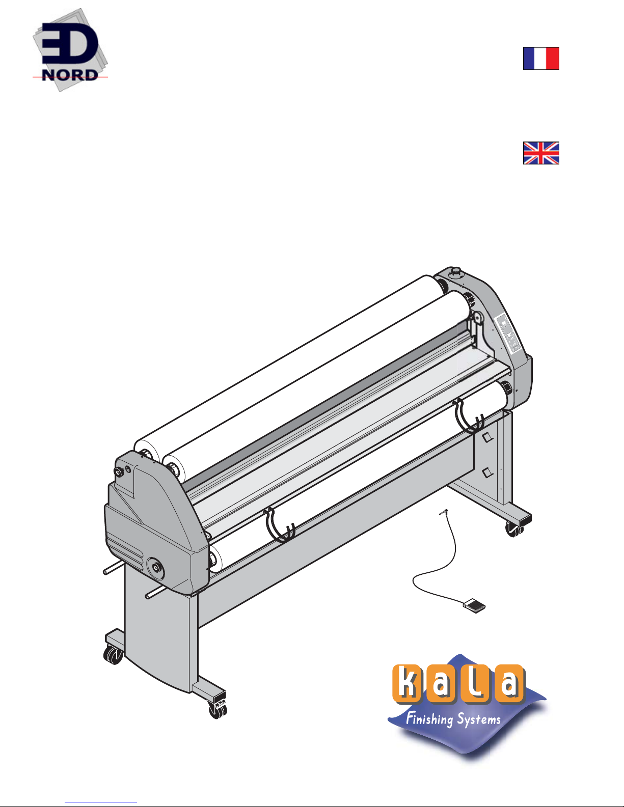
Mistral 1600 HR
2000 HR
MANUEL
UTILISATEUR
USER’S
MANUAL
EDNord - Istedgade 37A - 9000 Aalborg - telefon 9633 3500
Page 2

KALA S.A.S.
Parc de l'Ecotay
35 410 Nouvoitou - France
Tel. : +33 (0)2 99 37 64 64
Fax : +33 (0)2 99 37 64 65
EDNord - Istedgade 37A - 9000 Aalborg - telefon 9633 3500
Page 3
8
F
6
5
2
1
10
11
12
13
19
9
16
17
18
16
D
C
7
15
B
A
14
4
3
1
EDNord - Istedgade 37A - 9000 Aalborg - telefon 9633 3500
Page 4
Rep Désignation
1
2
3
4
5
6
7
8
9
10
11
12
13
14
15
16
17
18
19
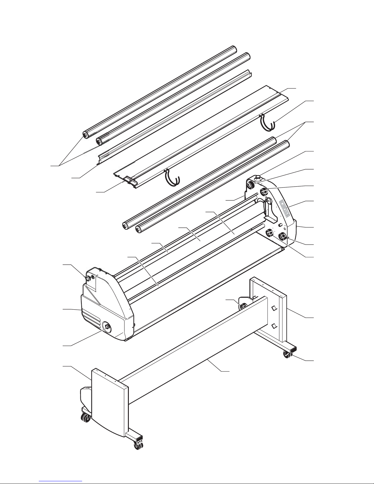
Axes autobloquants
Carter de protection
Table de travail
Paniers support document
Butée latérale
Capot gauche
Capot droit
Poignée supérieure de réglage de la tension des films
Poignée inférieure de réglage de la tension des films
Barre de tension supérieure
Barre de tension inférieure
Rouleau chauffant supérieur
Rouleau inférieur
Bouton d'arrêt d'urgence
Panneau de commande
Côtés du stand
Cloison du stand
Roulettes à freins
Interrupteur principal
Composants de la plastifieuse
Parts list of the laminator
Item
Designation
1
2
3
4
5
6
7
8
9
10
11
12
13
14
15
16
17
18
19
Self-locking axles
Safety cover
Working table
Document support trays
Lateral stop
Left-hand cover guard
Right-hand cover guard
Upper film tension adjustment handle
Lower film tension adjustment handle
Upper tension bar
Lower tension bar
Upper heating roller
Lower roller
Emergency stop button
Control panel
Stand sides
Middle plate
Self-lockable casters
Main switch
Componentes de la plastificadora
Ref Designación
1
2
3
4
5
6
7
8
9
10
11
12
13
14
15
16
17
18
19
Ejes autoblocantes
Cárter de protección
Mesa de trabajo
Cesto soporte documento
Tope laterale
Cubierta izquierda
Cubierta derecha
Puño superior de ajuste de
la tensión de las peliculas
Puño inferior de ajuste de la
tensión de las peliculas
Barra de tensión superior
Barra de tensión inferior
Rollo calentador superior
Rollo inferior
Botón de parada de emergencia
Cuadro de mandos
Lados del soporte
Tabique del soporte
Ruedecillas
Principal interruptor
Pos Bezeichnung
1
2
3
4
5
6
7
8
9
10
11
12
13
14
15
16
17
18
19
selbstblockierende Auf- bzw.
Abwickelachsen
Schutzabdeckung aus
Paniers support
Anlegetisch
Dokumentenhalter
Seitenanschlag
Abdeckung links
Abdeckung rechts
Einstellknopf obere Folien-
spannung
Einstellknopf untere Folien-
spannung
obere Spannleiste
untere Spannleiste
oberer Heizzylinder
unterer Zylinder
Notausschalter
Berührungsfeld-Steuerpult
Untergestell-Seitenteile
Untergestell-Mittelteil
Laufrollen
Hauptschalter
Bauteile des laminators
Componenti della plastificatri
ce
Rif. Descrizione
1
2
3
4
5
6
7
8
9
10
11
12
13
14
15
16
17
18
19
Assi autoblocanti
Carter di protezione
Piano di alimentazione
Vassoi supporto documento
Arresto laterale
Calotta sinistra
Calotta destra
Manopola superiore di regolazione della tensione dei film
Manopola inferiore di regolazione della tensione dei film
Barra di tensione superiore
Barre di tensione inferiore
Rullo riscaldente superiore
Rullo inferiore
Pulsante di arresto d’emergenza
Pannello di controllo
Lati del supporto
Divisorio del supporto
Rotelle
Interruttore principale
EDNord - Istedgade 37A - 9000 Aalborg - telefon 9633 3500
Page 5
b
c
f
h
d
e
g
a
i
j
k
MISTRAL 2000 HR MISTRAL 1600 HR
a
b
n
m
l
l
p
q
r
t
v
s
d
c
o
f
h
k
p
q
u
w
EDNord - Istedgade 37A - 9000 Aalborg - telefon 9633 3500
Page 6

Rep Désignation
a
b
c
d
e
f
g
h
i
j
k
l
m
n
o
p
q
r
s
t
u
v
w
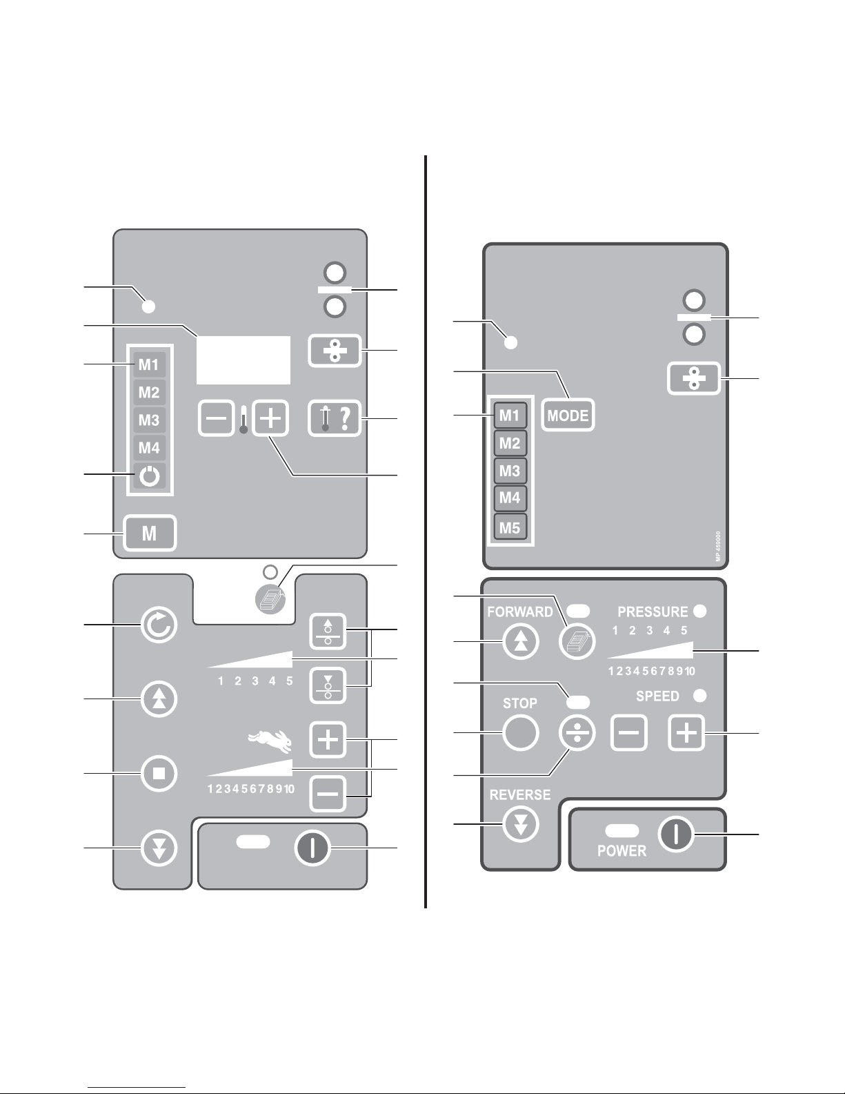
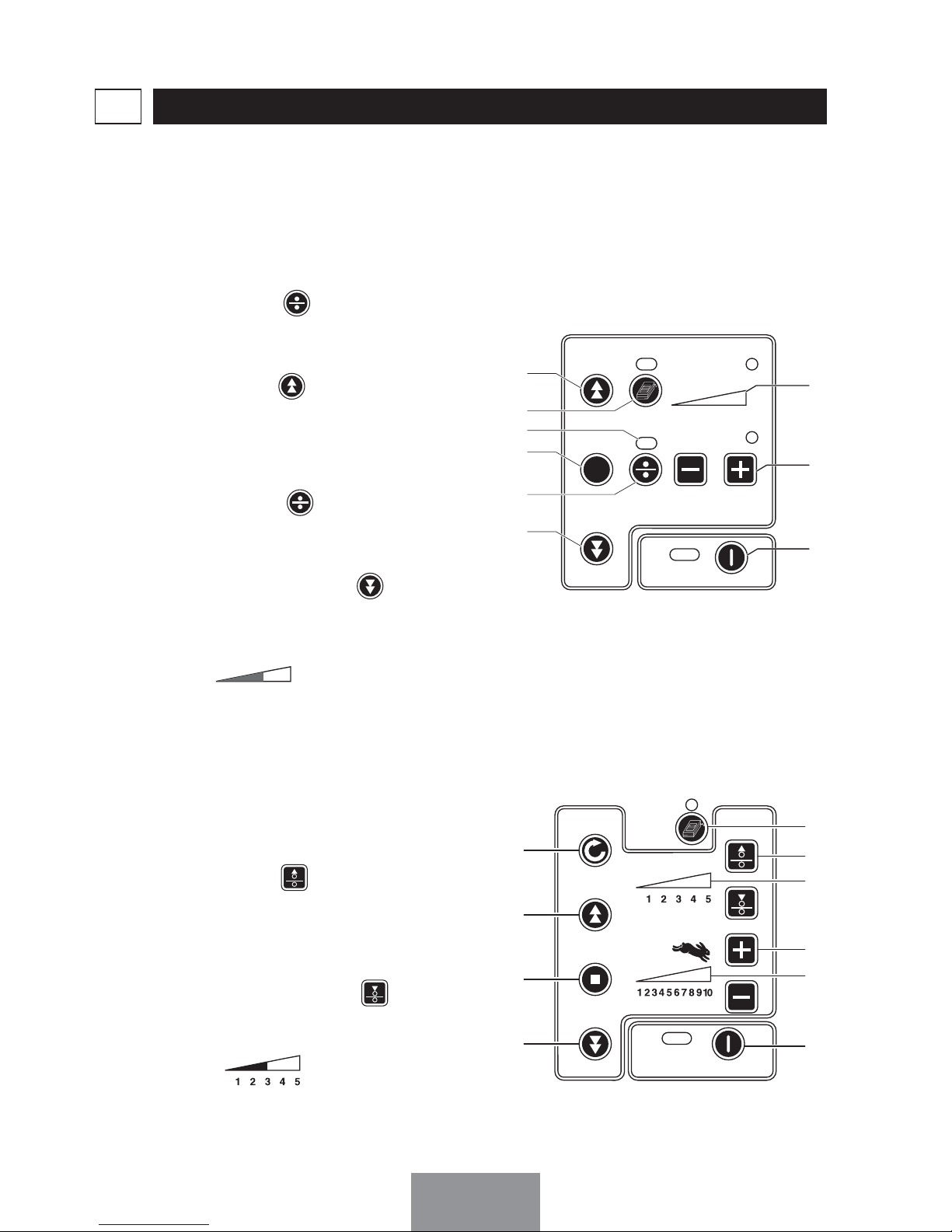
Sélection des mémoires et du
mode de plastification
Visualisation du programme actif
Marche avant des rouleaux +
montée du rouleau supérieur
Commande par pédale
Visualisation du mode "écartement des rouleaux"
Arrêt du moteur d’avance
Sélection écartement des rouleaux
Marche arrière des rouleaux +
descente du rouleau supérieur
Affichage digital de la pression
ou de la vitesse des rouleaux
Réglage de la vitesse
Marche/Arrêt panneau de commande
Voyant température atteinte
Affichage de la température
Mise en veille de la chauffe
Réinitialisation de la machine
Voyant de chauffe du rouleau
Mise en chauffe du rouleau
Mesure de la température de
mise en chauffe du rouleau
Réglage de la chauffe
Réglage de la pression
Affichage digital de la pression
Réglage de la vitesse
Affichage digital de la vitesse
Panneau de commande
Item
Designation
a
b
c
d
e
f
g
h
i
j
k
l
m
n
o
p
q
r
s
t
u
v
w
Selection of the memories and
of the mode of lamination
Visualisation of the active program
Forward motion of the roller +
rise of the upper roller
Using pedal switch
Visualisation of the mode “Spacing of the rollers”
Motor stop
Selection spacing of the rollers
Reverse motion of the rollers +
descent of the upper roller
Roller pressure or speed digital
display
Speed adjustment
Control panel switch
Required temperature light
Display of the temperature
Stand-by of the heating
Reinitialization of the machine
Light of roller heating
Roller heating
Measuring of the temperature
of the roller heating
Adjustment of the heating
Adjustment of the pressure
Digital pressure display
Adjustment of the speed
Digital speed display
Control panel
Ref Designación
a
b
c
d
e
f
g
h
i
j
k
l
m
n
o
p
q
r
s
t
u
v
w
Selección de las memorias y
del modo de laminación
Visualización programa activo
Marcha delantera de los rollos +
subida del rollo superior
Control mediante pedal
Visualización del modo “distancia de los rollos”
Parada de los motores de adelanto
Selección distancia de los rollos
Marcha atrás de los rollos +
descenso del rodillo superior
Visualización digital de la presión
o de la velocidad de los rollos
Ajuste de la velocidad
Interruptor del cuadro de mandos
Piloto de temperatura alcanzad
a
Visualización de la temperatura
Puesta en vela de la calefacción
Reinicialización de la máquina
Piloto de calefacción del rollo
Puesta en calentamiento del rollo
Medida de la temperatura de la
puesta en calentamiento del
rollo
Ajuste de la calefacción
Ajuste de la presión
Visualización digital de la presión
Ajuste de la velocidad
Visualización digital de la velocidad
Cuadro de mandos
Pos
Bezeichnung
a
b
c
d
e
f
g
h
i
j
k
l
m
n
o
p
q
r
s
t
u
v
w
Auswahl Speicher und Betriebsart
Anzeige aktives Programm
Walzen vorwärts laufen lassen
und obere Walze hochfahren
Fußschalter
Betriebsanzeige "Walzen öffnen"
Stopp Vorlaufmotor
Auswahl Walzenöffnung
Walzen rückwärts laufen lassen
und obere Walze senken
digitale Druckanzeige oder
Walzenge-schwindigkeitsanzeige
Geschwindigkeitseinstellung
Ein/Aus Steuerpult
Leuchtdiode Temperatur erreicht
Temperaturanzeige
Heizung Stand-By
Maschine reinitialisieren
Anzeige Walzen heizen
Heizen der Walzen
Temperaturmessung beim Heizen der Walzen
Temperatureinstellung
Druckeinstellung
digitale Druckanzeige
Geschwindigkeitseinstellung
digitale Geschwindigkeitsanzeige
Berührungsfeld-Steuerpult
Rif. Descrizione
a
b
c
d
e
f
g
h
i
j
k
l
m
n
o
p
q
r
s
t
u
v
w
Selezione della memorie e della
modalità di plastificazione
Visualizzazione del programma
attivo
Marcia in avanti dei rulli + salita
del rullo superiore
Comando tramite pedale
Visualizzazione della modalità
“distanza dei rulli”
Arresto motore avanzamento
Selezione distanza dei rulli
Marcia indietro dei rulli + discesa del rullo superiore
Display digitale della pressione
o della velocità dei rulli
Regolazione della velocità
ON / OFF Quadro comandi
Spia raggiungimento temperatura
Display della temperatura
Stand-by riscaldamento
Reimpostazione della macchina
Spia riscaldamento rulli
Riscaldamento rulli
Misurazione temperatura riscaldamento rulli
Regolazione riscaldamento
Regolazione della pressione
Display digitale della pressione
Regolazione della velocità
Display digitale della velocità
Pannello di controllo
EDNord - Istedgade 37A - 9000 Aalborg - telefon 9633 3500
Page 7

Déclaration de conformité
Voltage 220-240V :
• Directive machines : (98/37 CEE) incluant :
• Directive basse tension (73/23 CEE) selon la
norme EN 60204 - 1 (1997)
• Directive Compatibilité Electromagnétique
(89/336 CEE) selon la norme EN 55014,
Edition 1993 et EN 55014-2 Edition 1997.
KALA S.A.S.
Parc de l’Ecotay
35 410 NOUVOITOU
FRANCE.
Déclare que le produit suivant :
Modèle : MISTRAL est conforme aux exigences
suivantes
Toujours à la recherche du progrès, nous nous réservons le droit de modifier sans préavis les modèles ainsi que les équipements et leurs caractéristiques techniques.
Konformitätsbestätigung
Spannung 220-240V:
• Maschinenrichtlinie: (98/37 CEE) :
• Niederspannungs-Richtlinie (73/23 CEE)
gemäss EN 60204 – 1 (1997)
• Richtlinie bezüglich der elektromagnetischen
Verträglichkeit (89/336 CEE) gemäss EN 55014,
Ausgabe 1993 und EN 55014-2 Ausgabe 1997
KALA S.A.S.
Parc de l’Ecotay
35 410 NOUVOITOU
FRANCE.
bestätigt, daß folgendes Produkt:
Modell MISTRAL folgende Forderungen erfüllt
Sempre alla ricerca di innovazioni, ci riserviamo il diritto di modificare senza preavviso i modelli, le apparecchiature e le loro caratteristiche tecniche.
Dichiarazione di conformità
Tensione 220-240V:
• Direttiva macchina: (98/37 CEE) :
• Direttiva bassa tensione (73/23 CEE) confor-
memente alla normativa EN 60204 - 1 (1997)
•
Direttiva Compatibilità Elettromagnetica (89/336
CEE) conformemente alla normativa EN 55014,
Edizione 1993 e EN 55014-2 Edizione 1997
KALA S.A.S.
Parc de l’Ecotay
35 410 NOUVOITOU
FRANCE.
Dichiara che il seguente prodotto:
Modello: MISTRAL è conforme alle seguenti direttive
Sempre alla ricerca di innovazioni, ci riserviamo il diritto di modificare senza preavviso i modelli, le apparecchiature e le loro caratteristiche tecniche.
Declaración de conformidad
Voltaje 220 - 240V:
• Directiva máquina: (98/37 CEE) :
• Directiva baja tensión (73/23 CEE) según la
norma EN 60204 - 1 (1997)
• Directiva Compatibilidad Electromagnética
(89/336 CEE) según las normas EN 55014,
Edición 1993 y EN 55014-2
KALA S.A.S.
Parc de l’Ecotay
35 410 NOUVOITOU
FRANCE.
Declara que el producto siguiente:
Máquina modelo MISTRAL está en conformidad
con las exigencias siguientes
Siempre en pos del mayor progreso, nos reservamos el derecho de modificar sin aviso previo las características y los equipos técnicos de los modelos.
Declaration of conformity
Voltage 220-240V:
• Machine Directive : (98/37 EEC) :
• Low voltage Directive (73/23 EEC) according
to the EN 60204 – 1 (1997)
• Electromagnetic compatibility Directive (89/336
EEC) according to the EN 55014, Edition 1993
and EN 55014-2 Edition 1997.
KALA S.A.S.
Parc de l’Ecotay
35 410 NOUVOITOU
FRANCE.
Declares that the following product:
MISTRAL Model conforms to the following requirements
Always seeking to make progress, we reserve ourselves the right to change without notice the models as well as the equipment and their technical features.
EDNord - Istedgade 37A - 9000 Aalborg - telefon 9633 3500
Page 8

Garantie
Réglementation de retour :
Si votre Mistral ne fonctionne pas bien, relisez d'abord les
instructions. Si le fonctionnement défectueux ne peut-être
corrigé, demandez conseil à votre fournisseur. Assurezvous que le numéro de série et la date d'achat de votre
appareil soient à portée de main. Si vous devez retourner
la machine au fournisseur, elle devra être dans son emballage d’origine. Les dommages de transport résultants d'un
emballage défectueux ne sont pas couverts selon les termes de cette garantie.
Votre Mistral est garantie contre tous défauts de matériaux
et de fabrication pendant une période d'un an après la
date d'achat. En cas de défauts de matériaux ou de fabrication, la société ayant vendu l'appareil réparera celui-ci
dans ses ateliers ou le retournera au fabricant. Il n'existe
aucune garantie autre que celle qui vient d'être mentionnée ci-dessus. Cette garantie ne couvre pas les dommages particuliers ou résultants de causes indirectes, qu'ils
soient ou non prévisibles. La garantie ne couvre pas les
mauvaises utilisations de la machine.
Warranty
Return regulations:
If your Mistral does not work correctly, first read the
instructions again. If the defective operation cannot be
corrected, consult your supplier. Make sure that the series
number and the date of purchase of your machine are to
hand, if you have to return the machine to the supplier.
Damage during transport resulting from defective packaging is not covered under the terms of this guarantee.
Your Mistral is guaranteed against all defects of materials
and manufacturing for a period of one year from the date
of purchase. In the event of defects of materials or manufacturing, the company which sold the instrument will
repair it or it will be returned to the manufacturer. There is
no warranty other than the one mentioned above. This
warranty does not cover individual damage or damage
resulting from indirect causes, whether foreseeable or not.
The warranty does not cover incorrect use of the machine.
Garantie
Rücksendungs-Regelung:
Falls Ihre Mistral nicht richtig funktionieren sollte, lesen
Sie zuerst noch einmal die Anweisungen durch. Wenn das
Problem nicht behoben werden kann, fragen Sie Ihren
Händler um Rat. Stellen Sie sicher, daß die
Seriennummer und das Einkaufsdatum Ihres Geräts griffbereit sind, falls Sie die Maschine zum Händler zurücksenden müssen. Die Transportschäden, die von einer fehlerhaften Verpackung herrühren, stellen keinen
Garantiefall dar.
Ihre Mistral Maschine weist vom Kaufdatum ab eine einjährige Garantie gegen jeglichen Material- und Herstellungsfehler
auf. Falls Material- oder Herstellungsfehler auftreten sollten,
so wird die Firma, die das Gerät verkauft hat, dieses in ihren
eigenen Werkstätten reparieren oder an den Hersteller
zurücksenden. Es gibt keinerlei andere Garantie als die
obengenannte. Diese Garantie deckt nicht die besonderen
Schäden oder die Schäden, die indirekt verursacht worden
sind, ob diese vorhersehbar sind oder nicht. Die Garantie
deckt nicht die falschen Anwendungen der Maschine.
Garanzia
Disposizioni per la restituzione:
Se la vostra Mistral non funziona correttamente, si consiglia innanzitutto di rileggere il libretto d’istruzioni. Qualora
non fosse possibile correggere il funzionamento difettoso,
chiedete consiglio al vostro fornitore. Accertatevi di avere
sotto mano il numero di serie della macchina e la data di
acquisto nel caso in cui dobbiate restituire la macchina al
fornitore. I danni da trasporto dovuti ad un imballaggio
difettoso non sono coperti ai sensi delle condizioni della
presente garanzia.
La garanzia della vostra Mistral copre tutti i difetti di materiale e di fabbricazione per un anno a partire dalla data di
acquisto. In caso di difetti di materiale o di fabbricazione,
la società che ha venduto la macchina provvederà a ripararla presso il proprio servizio assistenza o a restituirla al
fabbricante. Non esiste altra garanzia oltre a quella sopra
citata. Tale garanzia non copre i danni speciali o dovuti a
cause indirette, indipendentemente dal fatto che siano o
meno prevedibili. La garanzia non copre i danni legati ad
un cattivo uso della macchina.
Garantía
Reglamentación de devolución:
Si su máquina Mistral no funciona bien, lea de nuevo las
instrucciones. Si el funcionamiento defectuoso no puede
corregirse con éstas, solicite consejo a su proveedor.
Cerciórese de que el número de serie y la fecha de compra del aparato están al alcance de la mano, si debe
devolver la máquina al proveedor. Los daños de transporte que resulten de un embalaje defectuoso no están
cubiertos por esta garantía.
La máquina Mistral está garantizada contra todos los
defectos de material y fabricación durante un periodo de
un año después de la fecha de compra. En caso de defectos de material o fabricación, la sociedad que ha vendido
el aparato lo reparará en sus talleres o lo devolverá al
fabricante, no habiendo ninguna otra garantía. Estas
garantía no cubre los daños particulares o que resulten de
causas indirectas, previsibles o imprevisibles. La garantía
no cubre la mala utilización de la máquina.
EDNord - Istedgade 37A - 9000 Aalborg - telefon 9633 3500
Page 9

SOMMAIRE
LA RÉCEPTION DE VOTRE MACHINE1
PAGE 3
PROGRAMMATION DE LA VITESSE ET DE LA TEMPÉRATURE
DES ROULEAUX
2
PAGE 4
RÉGLAGE DE LA PRESSION DES ROULEAUX3
PAGE 6
RÉGLAGE DE LA TENSION DES FILMS4
PAGE 7
PLASTIFICATION À FROID5
PAGE 7
RÉGLAGES6
PAGE
31
CARACTÉRISTIQUES TECHNIQUES7
PAGE 31
ENTRETIEN ET SÉCURITÉ8
PAGE 32
CONDITIONNEMENT DES BOBINES DE FILM9
PAGE 33
INCIDENTS POUVANT SURVENIR10
PAGE 33
MAINTENANCE11
PAGE 34
M
ISE AU REBUT
12
PAGE 34
Le choix de l'emplacement1-1
PAGE 3
Le déballage de votre machine à plastifier1-2
PAGE 3
MISTRAL 1600 HR1-3
PAGE 3
MISTRAL 2000 HR1-4
PAGE 4
Mise en veille automatique de la Mistral 2000 HR2-1
PAGE 4
Programmation de la vitesse2-2
PAGE 4
Programmation de la température2-3
PAGE 5
Plastification une face5-1
PAGE 7
Plastification une face et adhésivage simultané5-2
PAGE 12
Plastification recto-verso5-3
PAGE
20
Montage et contre-collage sur support5-4
PAGE
26
Accessoires et options5-5
PAGE 28
MISTRAL 1600 HR7-1
PAGE 31
MISTRAL 2000 HR7-2
PAGE 32
Entretien8-1
PAGE 32
Sécurité : test hebdomadaire8-2
PAGE 33
Kit de démarrage de films1-5
PAGE 4
EDNord - Istedgade 37A - 9000 Aalborg - telefon 9633 3500
Page 10

2
Ne pas laisser le cordon d'alimentation en contact avec une surface
chaude.
La plastifieuse doit être située
dans un local aéré.
Couper l’alimentation générale de
la machine à l’aide de l’interrupteur (Rep.19) après chaque utilisation.
Lors du montage de la machine,
faire attention au quartz et aux
surfaces au sol (vibrations). Si la
machine doit être démontée, faire
appel à un technicien.
Ne pas toucher la prise avec les
mains humides.
Pour débrancher l'appareil, tirer
sur la prise et non sur le cordon
d'alimentation.
Pour prévenir des chocs électriques, ne pas utiliser la machine
à plastifier près d'un point d'eau.
Dégager une zone de travail à
l'arrière de la machine.
Ne pas verser d'eau sur la machine à plastifier, ni sur le cordon
électrique, ni sur la prise de courant.
Ne pas utiliser la plastifieuse si le
cordon d'alimentation est endommagé.
La tension de votre machine correspond à celle de votre réseau
électrique.
L'alimentation de la machine
nécessite la mise à disposition
d'un socle de prise de courant
compatible CEI 60309-1.
INSTALLER LA MACHINE À PLASTIFIER SUR UN PLAN DE TRAVAIL STABLE
, À
PROXIMITÉ D'UNE PRISE DE COURANT FACILE D'ACCÈS.
La ligne d'alimentation doit être
conforme aux règles d'installations
de la norme NFC 15 100.
VÉRIFIER QUE :
EDNord - Istedgade 37A - 9000 Aalborg - telefon 9633 3500
Page 11
3
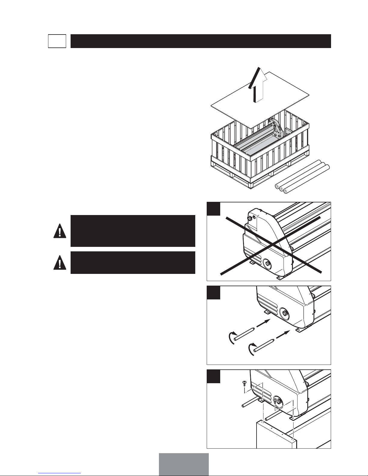
Ôter le couvercle de la caisse.
Les mandrins et les accessoires sont
dans l'emballage, retirez-les.
Avant de déballer votre plastifieuse, il
est nécessaire de déterminer votre
zone de travail : Vous devez pouvoir
accéder aisément à toutes les parties
de la machine.
La machine est lourde. Un minimum
de 4 personnes est requis pour
cette opération.
LA RÉCEPTION DE VOTRE MACHINE1
Le choix de l'emplacement1-1
Le déballage de votre machine à
plastifier
1-2
Mistral 1600 HR : Le positionnement
de la plastifieuse sur le stand
1-3
• Saisir la machine par les poignées.
• Positionner la machine sur le stand.
• Fixer l'ensemble à l'aide des vis
livrées avec le stand.
Ne saisissez pas la machine par les
capots latéraux.
1
2
3
EDNord - Istedgade 37A - 9000 Aalborg - telefon 9633 3500
Page 12
4
Mistral 1600 HR
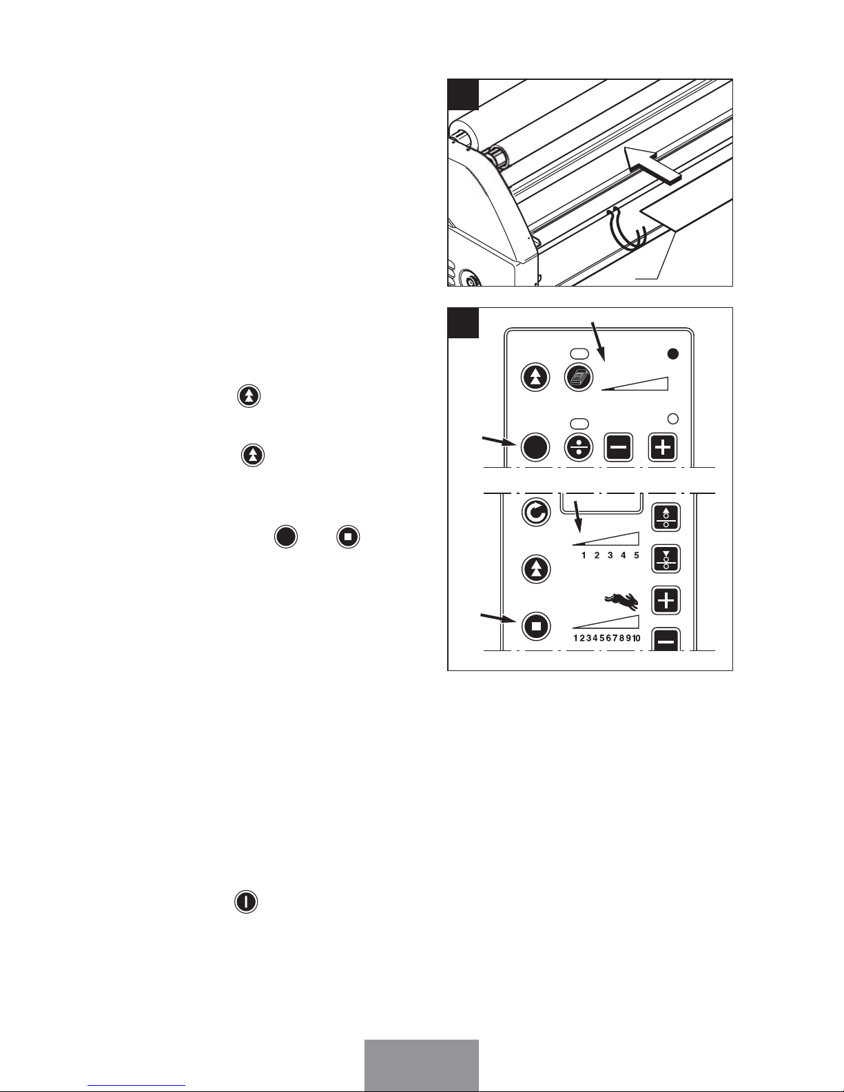
Pour programmer la vitesse, le voyant
(e) doit être éteint. Si ce n'est pas le
cas, appuyer sur (g).
Régler la vitesse des rouleaux en
appuyant sur les touches et
(j) du panneau de commande.
La dernière valeur utilisée remplace
automatiquement la précédente dans
la mémoire.
R
EVERSE
STOP
SPEE
D
12345
12345
6789
10
FORW
ARD
PRESSURE
POWE
R
c
f
h
d
e
g
i
j
k
Vous trouverez dans l'emballage un
kit de démarrage de films complet
comprenant :
Kit de démarrage de films1-5
Programmation de la vitesse2-2
- Un rouleau de film de montage
(double face).
- Deux rouleaux de film adhésif à froid.
P
ROGRAMMATION DE LA VITESSE ET DE LA TEMPÉRATURE DES ROULEAUX
2
Mise en veille automatique de la
Mistral 2000 HR
2-1
Les mémoires M1, M2, M3 et M4 sont programmables par les utilisateurs.
Pour les sélectionner, appuyer successivement sur ou (a)
jusqu'à ce que le voyant correspondant à la mémoire désirée s'allume.
MOD
E
Le voyant (k) indique la mise en
veille automatique de la machine
lorsque celle ci n'est pas utilisée pendant 30 min. La température de veille
est réglable de 20 à 60°c. Les rouleaux
s’écartent automatiquement.
*Appuyer sur (n) pour mettre en veille
manuellement la chauffe du rouleau.
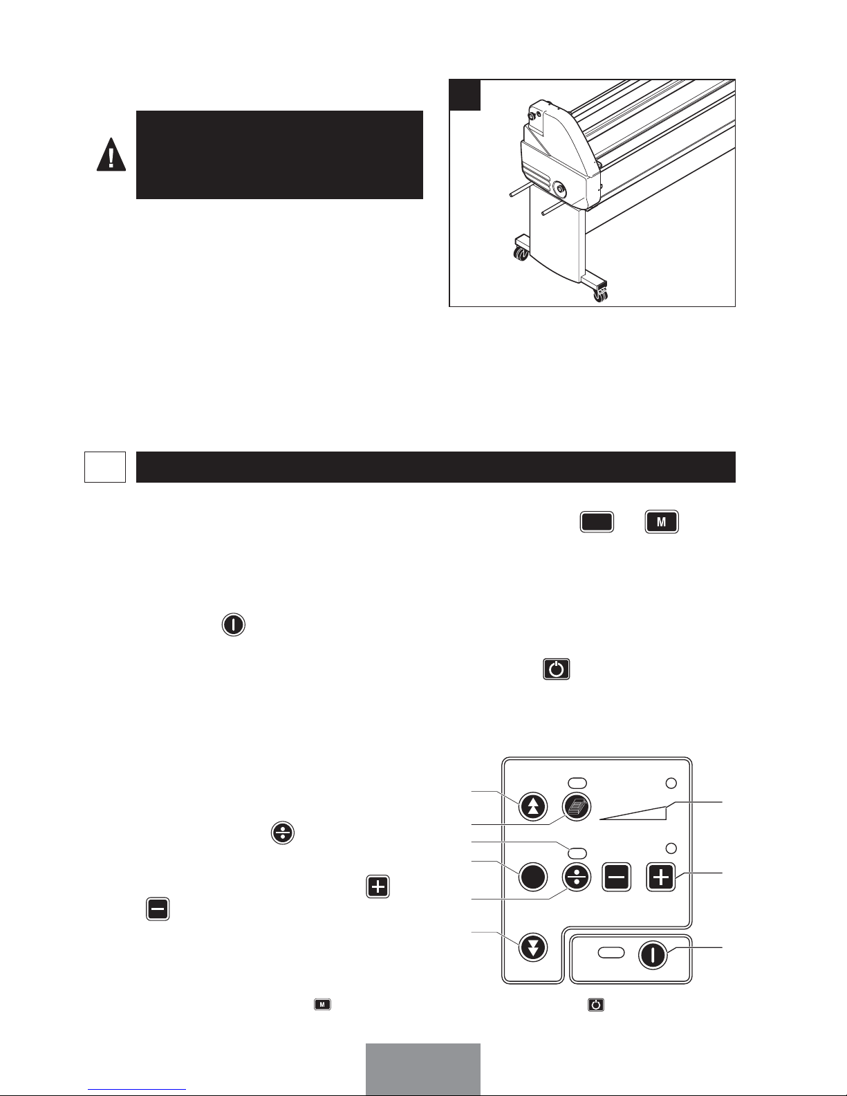
Mistral 2000 HR1-4
La Mistral 2000 HR est livrée positionnée sur son stand.
Saisir la machine par les poignées
pour la déplacer.
Désolidariser la M2000 HR de la pallette. Saisir la machine par les poignées, déplacer la afin de poser un
côté au sol, puis le second côté.
1
*Appuyer successivement sur (a) jusqu’a ce que le voyant corresponde à (n) , pour mettre en
veille manuellement le chauffage du rouleau.
EDNord - Istedgade 37A - 9000 Aalborg - telefon 9633 3500
Page 13

5
Mistral 2000 HR
Régler la vitesse des rouleaux en
appuyant sur les touches et
(v) du panneau de commande,
jusqu'à visualisation sur le panneau de
commande de la vitesse désirée
(w):
La dernière valeur utilisée remplace
automatiquement la précédente dans
la mémoire.
t
u
v
w
d
c
o
f
h
k
Mistral 2000 HR
Régler la température des rouleaux en
appuyant sur les touches (s)
du panneau de commande (entre 20 et
60°).
La dernière valeur utilisée remplace
automatiquement la précédente dans la
mémoire.
La mise en chauffe du rouleau se fait en
appuyant sur (q) et est indiquée
par le voyant (p).
Pour connaître la température du rouleau, appuyer sur (r).
Le voyant (l) allumé indique que la température programmée est atteinte.
Programmation de la température2-3
q
r
s
p
m
l
b
n
a
EDNord - Istedgade 37A - 9000 Aalborg - telefon 9633 3500
Page 14
6
Mistral 2000 HR
Réglage de la pression en cours de
plastification
Réglage de l'écartement des rouleaux :
1- Appuyer sur (t) jusqu'à obtention
de l'écartement maximum.
Réglage de la pression des rouleaux :
1- Maintenir appuyer sur (t) jusqu'à
visualisation sur le panneau de
commande de la pression désirée
(u) :
t
u
v
w
d
c
o
f
h
k
La Mistral est équipée d'un dispositif de réglage d'écartement et de pression des
rouleaux.
Ce dispositif permet l’utilisation de supports épais (Epaisseur maximale : 25 mm).
Mistral 1600 HR
Réglage de l'écartement des rouleaux :
1- Appuyer sur (g) si le voyant e et
le voyant "PRESSURE" ne sont pas
allumés ; la fonction est activée.
2- Appuyer sur (c) jusqu'à obtention
de l'écartement maximum.
Réglage de la pression des rouleaux :
1- Appuyer sur (g) si le voyant (e)
et le voyant "PRESSURE" ne sont
pas allumés ; la fonction est activée.
2- Maintenir appuyer sur (h) jusqu'à
visualisation sur le panneau de commande de la pression désirée
(i):
RÉGLAGE DE LA PRESSION DES ROULEAUX3
R
EVERSE
STOP
SPEE
D
12345
12345
6789
10
FORW
ARD
PRESSURE
POWE
R
c
f
h
d
e
g
i
j
k
12345
EDNord - Istedgade 37A - 9000 Aalborg - telefon 9633 3500
Page 15
7
Les poignées (Rep.8) et (Rep.9) permettent de régler la tension des films
présents sur les axes autobloquants.
Lors de la plastification, le film doit être
suffisamment tendu pour obtenir une
plastification parfaite. Il n'est cependant pas nécessaire de trop tendre le
film. Seuls des essais vous permettront de définir la tension adéquate. Si
des plis apparaissent au niveau des
rouleaux, augmenter légèrement la
tension du film.
Pour augmenter la tension des films,
tourner les poignées (Rep.8) ou
(Rep.9) dans le sens des aiguilles
d'une montre.
9
8
RÉGLAGE DE LA TENSION DES FILMS4
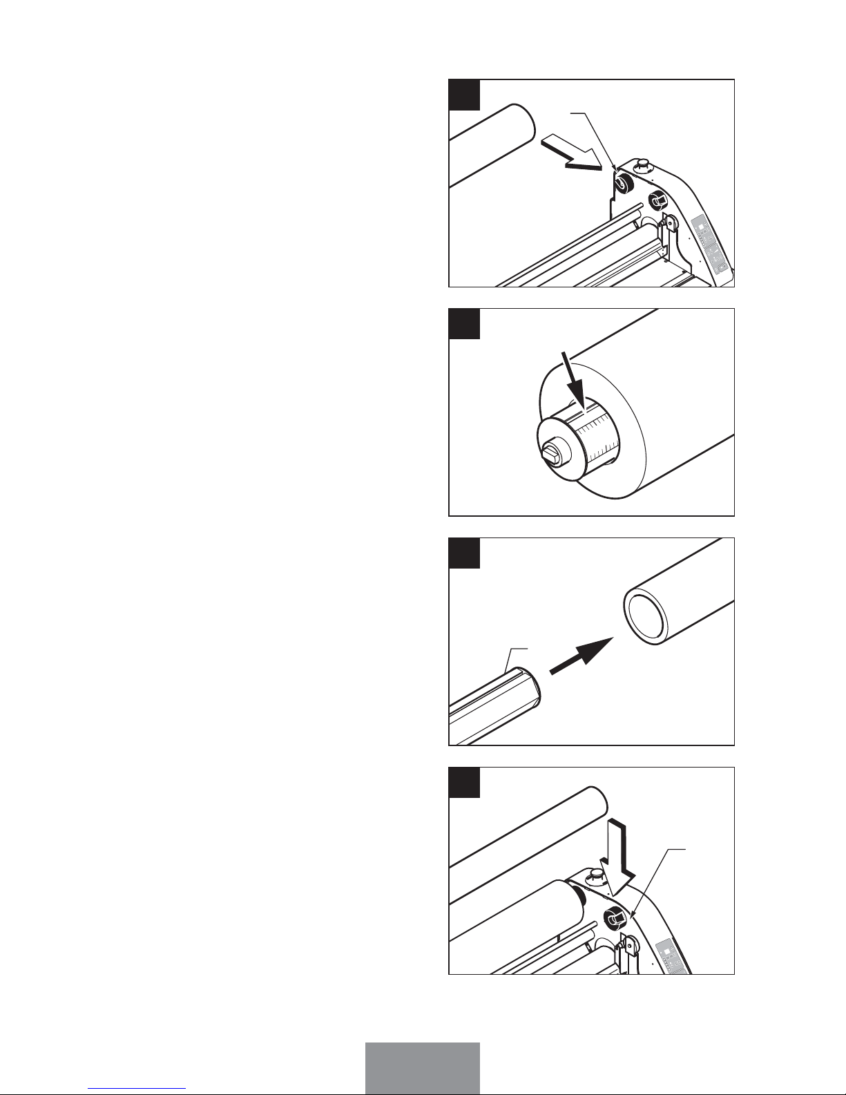
1
2
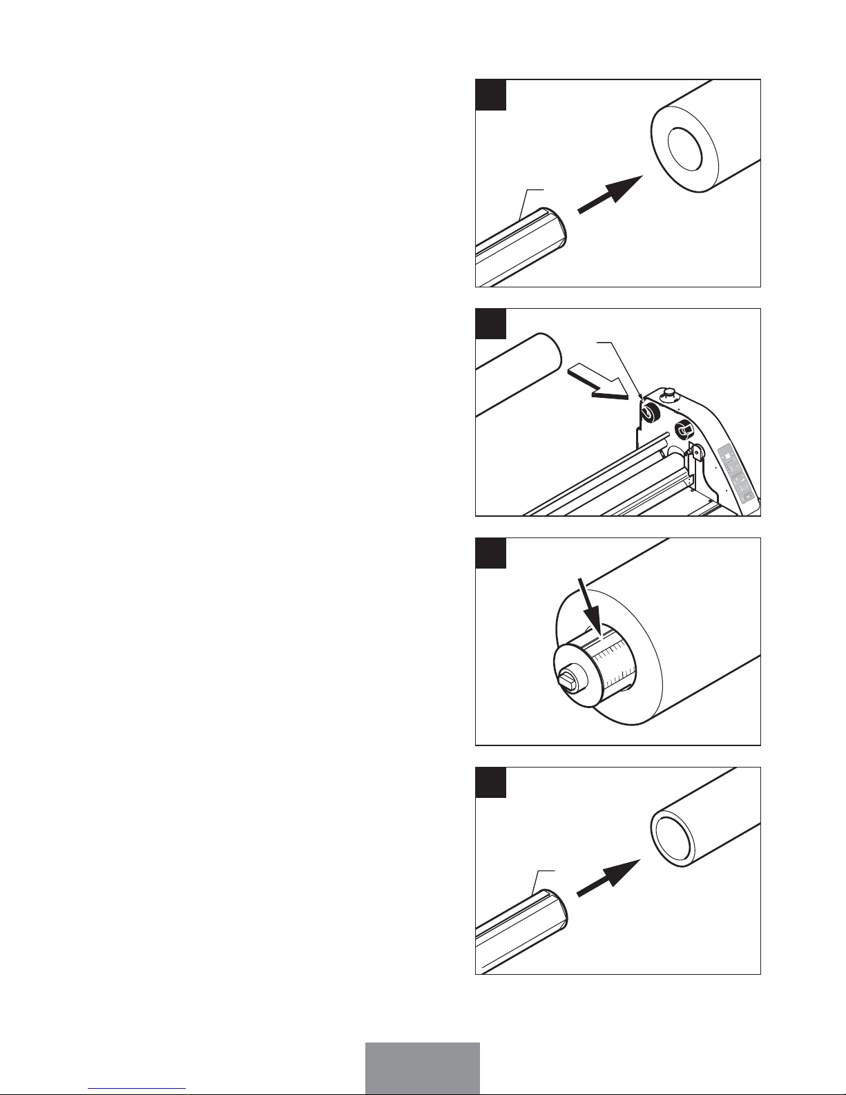
Introduire un axe autobloquant (Rep.1)
à l'intérieur du mandrin de la bobine de
film.
PLASTIFICATION À FROID5
Plastification une face5-1
1
1
Mettre la machine sous tension à l'aide
de l'interrupteur situé à l'arrière de la
machine (Rep.19). Le panneau de
commande s'allume.
Appuyer sur (k).
Mettre en chauffe les rouleaux si
besoin
(q)
.
EDNord - Istedgade 37A - 9000 Aalborg - telefon 9633 3500
Page 16
8
Placer l'ensemble sur la position (B)
de la machine.
B
M
P
4
39000
ESSU
RE
C
READY
MODE
MEAS.
5
Introduire un axe autobloquant (Rep.1)
à l'intérieur du tube en carton pour
récupérer le papier support de film.
1
4
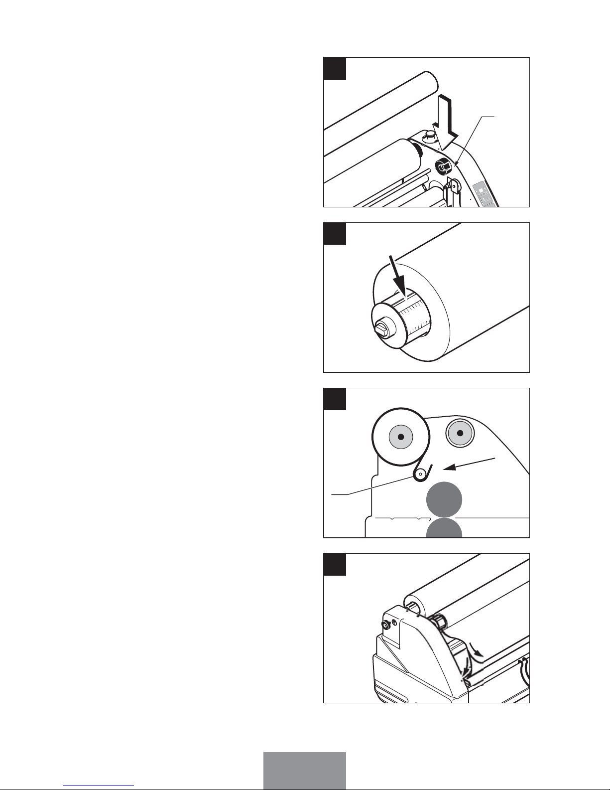
Placer l'ensemble sur la position (A)
de la machine (papier support de film
vers le haut).
A
M
P
4
3
9
0
0
0
REVERSE
STOP
SPEED
123
4
5
1
2 3
4
5
6
7
8
9
10
FOR
WARDP
RESS
U
RE
C
RE
ADY
MODE
M
EAS.
POWER
2
Centrer la bobine en vous aidant des
règles graduées présentes sur l’axe.
10
3
EDNord - Istedgade 37A - 9000 Aalborg - telefon 9633 3500
Page 17
9
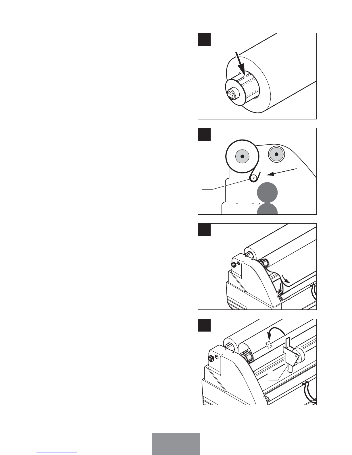
Centrer la bobine en vous aidant des
règles graduées présentes sur l’axe.
10
6
Passer le film et son support papier
derrière la barre de tension supérieure
(Rep.10).
10
7
Séparer le film de son support papier.
8
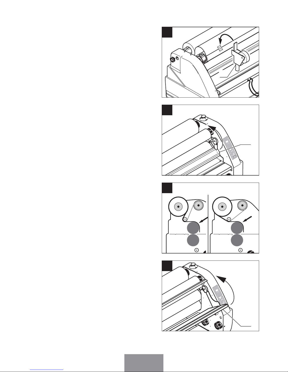
Adhésiver le support papier sur le tube
carton à l’aide d’un dévidoir pistolet
(Rep.23).
2
3
9
EDNord - Istedgade 37A - 9000 Aalborg - telefon 9633 3500
Page 18
10
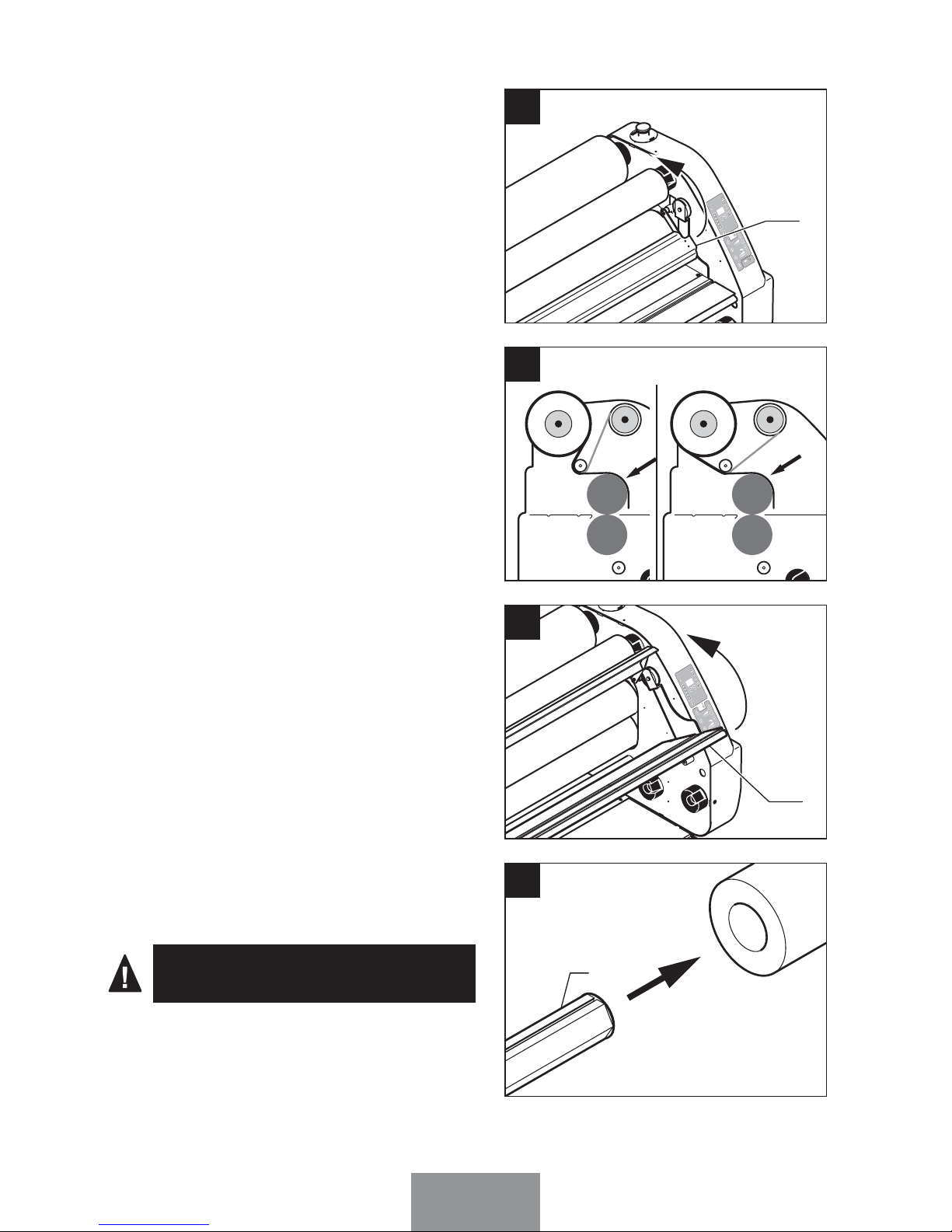
Introduire un axe autobloquant (Rep.1)
à l’intérieur du mandrin de la bobine de
papier.
1
13
Soulever la table de travail (Rep.3).
3
12
La bobine de papier doit être plus
large que la bobine de film.
Placer le film sur le rouleau laminateur
supérieur (face adhésive vers vous).
11
Soulever le carter de protection (Rep.2).
2
10
EDNord - Istedgade 37A - 9000 Aalborg - telefon 9633 3500
Page 19
11
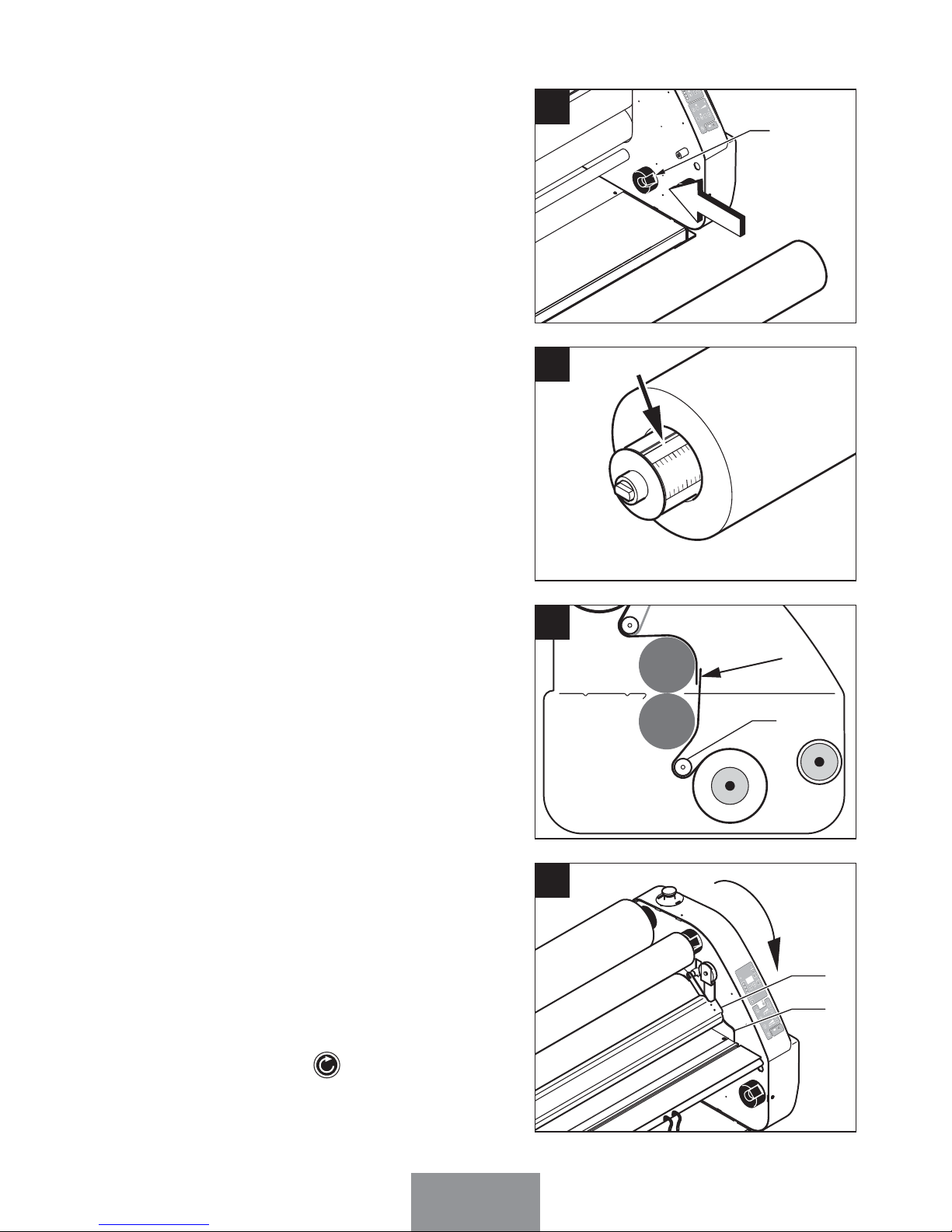
Coller le papier sur le film adhésif en
passant sous la barre de tension inférieure (Rep.11).
11
16
Placer l’ensemble sur la position (C)
de la machine.
C
M
P
4
3
9
0
0
0
REVERSE
STOP
SPEED
1
2
3
4
5
1
2
3
4
5
6
7
8
9
10
FORWARD PRESSURE
POWER
14
Centrer la bobine en vous aidant des
règles graduées présentes sur l’axe.
10
15
Baisser la table de travail (Rep.3) puis
le carter de protection (Rep.2).
Pour la Mistral 1600 HR :
Réinitialiser la machine avec le bouton
poussoir, situé sous la table, à droite.
Pour la Mistral 2000 HR :
Réinitialiser la machine en appuyant
sur la touche (o), située sur le
tableau de commande.
3
2
17
EDNord - Istedgade 37A - 9000 Aalborg - telefon 9633 3500
Page 20
12
Plastification une face et adhésivage
simultané
5-2
Mettre la machine sous tension à l'aide
de l'interrupteur situé à l'arrière de la
machine (Rep.19). Le panneau de
commande s'allume.
Appuyer sur (k).
Régler les rouleaux sur la position de
pression 1 (cf chapitre n°3).
Pour la Mistral 1600 HR :
Appuyer sur (c) en mode “speed”.
Pour la Mistral 2000 HR :
Appuyer sur (c) et accompagner la
plaque jusqu’à ce qu’elle sorte des
rouleaux.
Appuyer sur stop ou (f).
Couper le film à l’aide du cutter et
récupérer la plaque d’introduction.
Régler la pression des rouleaux suivant
application (cf chapitres n°3 et n°6).
STOP
SPEE
D
12345
12345
6789
10
FORW
ARD
PRESSURE
19
Pousser la plaque d’introduction
(Rep.22) entre les rouleaux.
22
18
EDNord - Istedgade 37A - 9000 Aalborg - telefon 9633 3500
Page 21
13
Introduire un axe autobloquant (Rep.1)
à l'intérieur du mandrin de la bobine de
film.
1
1
Placer l'ensemble sur la position (A)
de la machine (papier support de film
vers le haut).
A
M
P
4
3
9
0
0
0
REVERSE
STOP
SPEED
123
4
5
1
2 3
4
5
6
7
89
10
FOR
WARDP
RESS
U
RE
C
RE
ADY
MODE
M
EAS.
POWER
2
Centrer la bobine en vous aidant des
règles graduées présentes sur l’axe.
10
3
Introduire un axe autobloquant (Rep.1)
à l'intérieur du tube en carton pour
récupérer le papier support de film.
1
4
EDNord - Istedgade 37A - 9000 Aalborg - telefon 9633 3500
Page 22
14
Centrer la bobine en vous aidant des
règles graduées présentes sur l’axe.
10
6
Passer le film derrière la barre de tension supérieure (Rep.10).
10
7
Séparer le film de son support papier.
8
Placer l'ensemble sur la position (B)
de la machine.
B
M
P
4
39
00
0
ESSU
RE
C
READY
MODE
MEAS.
5
EDNord - Istedgade 37A - 9000 Aalborg - telefon 9633 3500
Page 23
15
Placer le film sur le rouleau laminateur
supérieur (face adhésive vers vous).
11
Soulever la table de travail (Rep.3).
3
12
Adhésiver le support papier sur le tube
carton à l’aide d’un dévidoir pistolet
(Rep.23).
2
3
9
Soulever le carter de protection (Rep.2).
2
10
EDNord - Istedgade 37A - 9000 Aalborg - telefon 9633 3500
Page 24

16
Pour la bobine de film double face :
- Introduire un axe autobloquant
(Rep.1) à l’intérieur du mandrin de la
bobine de film.
1
- Placer l’ensemble sur la position (C)
de la machine.
- Bloquer l’axe inférieur à l’aide de la
bague de blocage (cf chap. n°5-5-A).
C
M
P
4
3
9
0
0
0
REVERSE
STOP
SPEED
1
2
3
4
5
1
2
3
4
5
6
7
8
9
10
FORWARD PRESSURE
POWER
13A
- Centrer la bobine en vous aidant des
règles graduées présentes sur l’axe.
10
13B
13
- Coller le film adhésif inférieur sur le
film adhésif supérieur en passant
devant la barre de tension inférieure.
13C
Le film double face doit passer
devant la barre de tension.
EDNord - Istedgade 37A - 9000 Aalborg - telefon 9633 3500
Page 25

17
- Placer l’ensemble sur la position (C)
de la machine.
C
M
P
4
3
9
0
0
0
REVERSE
STOP
SPEED
1
2
3
4
5
1
2
3
4
5
6
7
8
9
10
FORWARD PRESSURE
POWER
14B
- Centrer la bobine en vous aidant des
règles graduées présentes sur l’axe.
10
14C
- Introduire un axe autobloquant
(Rep.1) à l'intérieur du tube en carton
pour récupérer le papier support de
film.
1
14D
- Placer l’ensemble sur la position (D)
de la machine.
D
REVERSE
STOP
S
PEED
1
2
3
4
5
1
2
3
4
5
6
7
8
9
1
0
FOR
WA
RD P
RESS
POWER
14E
Pour la bobine de film double face
avec papier protecteur double :
- Introduire un axe autobloquant
(Rep.1) à l’intérieur du mandrin de la
bobine de film.
1
14A
EDNord - Istedgade 37A - 9000 Aalborg - telefon 9633 3500
Page 26

18
- Passer le film et son support papier
sous la barre de tension inférieure
(Rep.11).
11
14F
- Séparer le film de son support papier.
M
P 43
90
00
REVERSE
STOP
SPEED
1
2
34
5
1
2 3
4
5
67
8
9
10
FORWARDPRESSURE
C
READY
MODE
MEAS.
POWER
14G
- Adhésiver le support papier sur le tube
carton à l’aide d’un dévidoir pistolet
(Rep.23).
23
M
P 4
390
00
REVERSE
STOP
S
PEED
1
2
345
1 2
3
4
5
67
8
9
10
FORWARD
PRESSURE
C
RE
ADY
MODE
MEAS.
POWER
14H
Coller le film adhésif inférieur sur le
film adhésif supérieur en passant sous
la barre de tension inférieure.
14I
EDNord - Istedgade 37A - 9000 Aalborg - telefon 9633 3500
Page 27

19
Pousser la plaque d’introduction
(Rep.22) entre les rouleaux.
22
16
Régler les rouleaux sur la position de
pression 1 (cf chapitre n°3).
Pour la Mistral 1600 HR :
Appuyer sur (c) en mode “speed”.
Pour la Mistral 2000 HR :
Appuyer sur (c) et accompagner la
plaque jusqu’à ce qu’elle sorte des
rouleaux.
Appuyer sur stop ou (f).
Couper le film à l’aide du cutter et
récupérer la plaque d’introduction.
Régler la pression des rouleaux suivant
application (cf chapitres n°3 et n°6).
STOP
SPEE
D
12345
12345
6789
10
FORW
ARD
PRESSURE
17
Baisser la table de travail (Rep.3) puis
le carter de protection (Rep.2).
Pour la Mistral 1600 HR :
Réinitialiser la machine avec le bouton
poussoir, situé sous la table, à droite.
Pour la Mistral 2000 HR :
Réinitialiser la machine en appuyant
sur la touche (o), située sur le
tableau de commande.
3
2
15
EDNord - Istedgade 37A - 9000 Aalborg - telefon 9633 3500
Page 28

20
Placer l'ensemble sur la position (A)
de la machine (papier support de film
vers le haut).
A
M
P
4
3
9
0
0
0
STOP
SPEED
123
4
5
1
2 3
4
5
6
7
8
9
10
FOR
WARDP
RESS
U
RE
C
RE
ADY
MODE
M
EAS.
2
Centrer la bobine en vous aidant des
règles graduées présentes sur l’axe.
10
3
Introduire un axe autobloquant (Rep.1)
à l'intérieur du tube en carton pour
récupérer le papier support de film.
1
4
Plastification recto-verso5-3
Introduire un axe autobloquant (Rep.1)
à l'intérieur du mandrin de la bobine de
film.
1
1
Mettre la machine sous tension à l'aide
de l'interrupteur situé à l'arrière de la
machine (Rep.19). Le panneau de
commande s'allume.
Appuyer sur (k).
EDNord - Istedgade 37A - 9000 Aalborg - telefon 9633 3500
Page 29

21
Centrer la bobine en vous aidant des
règles graduées présentes sur l’axe.
10
6
Passer le film derrière la barre de tension supérieure (Rep.10).
10
7
Séparer le film de son support papier.
8
Adhésiver le support papier sur le tube
carton à l’aide d’un dévidoir pistolet
(Rep.23).
2
3
9
Placer l'ensemble sur la position (B)
de la machine.
B
READY
E
MEAS.
5
EDNord - Istedgade 37A - 9000 Aalborg - telefon 9633 3500
Page 30

22
Placer le film sur le rouleau laminateur
supérieur (face adhésive vers vous).
11
Soulever la table de travail (Rep.3).
3
12
Soulever le carter de protection (Rep.2).
2
10
Introduire un axe autobloquant (Rep.1)
à l'intérieur du mandrin de la bobine de
film.
1
13
EDNord - Istedgade 37A - 9000 Aalborg - telefon 9633 3500
Page 31

23
Placer l’ensemble sur la position (C)
de la machine.
C
M
P
4
3
9
0
0
0
REVERSE
STOP
SPEED
1
2
3
4
5
1
2
3
4
5
6
7
8
9
10
FORWARD PRESSURE
POWER
14
Centrer la bobine en vous aidant des
règles graduées présentes sur l’axe.
10
15
Introduire un axe autobloquant (Rep.1)
à l'intérieur du tube en carton pour
récupérer le papier support de film.
1
16
Placer l’ensemble sur la position (D)
de la machine.
D
REVERSE
STOP
S
PEED
1
2
3
4
5
1
2
3
4
5
6
7
8
9
1
0
FOR
WA
RD PRESS
URE
POWER
17
EDNord - Istedgade 37A - 9000 Aalborg - telefon 9633 3500
Page 32

24
Passer le film et son support papier
sous la barre de tension inférieure
(Rep.11).
11
18
Séparer le film de son support papier.
M
P 43
90
00
REVERSE
STOP
SPEED
1
2
34
5
1
2 3
4
5
67
8
9
10
FORWARDPRESSURE
C
READY
MODE
MEAS.
POWER
19
Adhésiver le support papier sur le tube
carton à l’aide d’un dévidoir pistolet
(Rep.23).
23
M
P 4
390
00
REVERSE
STOP
S
PEED
1
2
345
1 2
3
4
5
67
8
9
10
FORWARD
PRESSURE
C
RE
ADY
MODE
MEAS.
POWER
20
Coller le film adhésif inférieur sur le
film adhésif supérieur en passant sous
la barre de tension inférieure.
21
EDNord - Istedgade 37A - 9000 Aalborg - telefon 9633 3500
Page 33

25
Pousser la plaque d’introduction
(Rep.22) entre les rouleaux.
22
23
Régler les rouleaux sur la position de
pression 1 (cf chapitre n°3).
Pour la Mistral 1600 HR :
Appuyer sur (c) en mode “speed”.
Pour la Mistral 2000 HR :
Appuyer sur (c) et accompagner la
plaque jusqu’à ce qu’elle sorte des
rouleaux.
Appuyer sur stop ou (f).
Couper le film à l’aide du cutter et
récupérer la plaque d’introduction.
Régler la pression des rouleaux suivant
application (cf chapitres n°3 et n°6).
STOP
SPEE
D
12345
12345
6789
10
FORW
ARD
PRESSURE
24
Baisser la table de travail (Rep.3) puis
le carter de protection (Rep.2).
Pour la Mistral 1600 HR :
Réinitialiser la machine avec le bouton
poussoir, situé sous la table, à droite.
Pour la Mistral 2000 HR :
Réinitialiser la machine en appuyant
sur la touche (o), située sur le
tableau de commande.
3
2
22
EDNord - Istedgade 37A - 9000 Aalborg - telefon 9633 3500
Page 34

26
Montage et contre-collage sur support
Sur le document adhésivé, décoller
une bande de papier de protection du
film d'environ 2 cm et la plier.
2
cm
Papier protecteu
r
1
Positionner le document et le coller sur
le support.
Papier protecteu
r
Document
Support
2
Ecarter les rouleaux au maximum
(cf. chapitre 3).
3
Soulever le carter de protection (Rep.2).
2
4
5-4
EDNord - Istedgade 37A - 9000 Aalborg - telefon 9633 3500
Page 35

27
Régler les rouleaux sur la position de
pression 1 (cf chapitre n°3).
Pour la Mistral 1600 HR :
Appuyer sur (c) en mode “speed”.
Pour la Mistral 2000 HR :
Appuyer sur (c).
Retirer le papier protecteur au fur et à
mesure de sa progression entre les
rouleaux laminateurs en le retenant
manuellement au-dessus du carter.
Appuyer sur stop ou (f).
STOP
SPEE
D
12345
12345
6789
10
FORW
ARD
PRESSURE
7
Présenter l'ensemble à adhésiver sur
la table de travail entre les rouleaux.
Poser le document à contre-coller sur la
barre de tension supérieure (Rep.10).
Support
Papier support
Document
10
5
Baisser le carter de protection (Rep.2).
Pour la Mistral 1600 HR :
Réinitialiser la machine avec le bouton
poussoir, situé sous la table, à droite.
Pour la Mistral 2000 HR :
Réinitialiser la machine en appuyant
sur la touche (o), située sur le
tableau de commande.
2
6
EDNord - Istedgade 37A - 9000 Aalborg - telefon 9633 3500
Page 36

28
Accessoires et fonction5-5
Elle maintient l’axe autobloquant inférieur en plastification une face ou/et adhésivage
simultané du document. Elle se place sur le palier de l’axe inférieur.
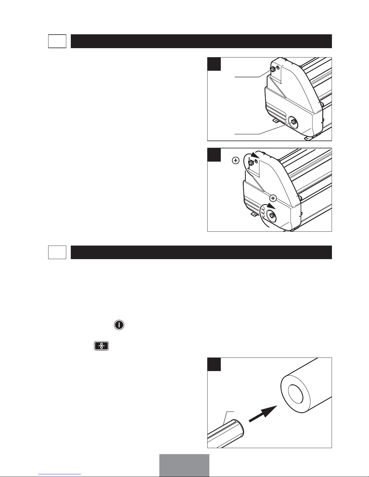
A - Bague de Blocage :
Tourner la bague d’un quart de tour
vers le haut.
M
P
4
3
9
0
0
0
REVERSE
STOP
SPEED
1
2
3
4
5
1
2
3
4
5
6
7
8
9
10
FORWARD PRESSURE
C
READY
MODE
MEAS.
POWER
A3
Placer la bague sur le palier.
M
P
4
3
9
0
0
0
REVERSE
STOP
SPEED
1
2
3
4
5
1
2
3
4
5
6
7
8
9
10
FORWARD PRESSURE
C
READY
MODE
MEAS.
POWER
A1
Positionner l’axe autobloquant.
REVERSE
STOP
S
POWER
A2
EDNord - Istedgade 37A - 9000 Aalborg - telefon 9633 3500
Page 37

29
Monter le flasque (Rep.26) côté droit
avec les vis fournies.
26
B1
B - Enrouleur :
Monter le flasque côté gauche (Rep.27)
avec les vis fournies.
27
B2
Monter la barre de renfort (Rep.28)
avec les vis fournies.
Connecter l’alimentation à l’enrouleur.
28
B3
Introduire un axe autobloquant (Rep.1)
à l’intérieur d’un mandrin cartonné.
1
B4
Un axe enrouleur vous permet de
bobiner le support plastifié en sortie
machine. Cet enrouleur est en option
sur le Mistral 1600 HR
EDNord - Istedgade 37A - 9000 Aalborg - telefon 9633 3500
Page 38

30
Placer l’ensemble sur la position (E)de
la machine.
E
B5
Adhésiver le document plastifié sur le
tube carton pour amorcer le bobinage.
B6
Mettre sous-tension l’enrouleur à l’aide
du bouton (Rep.24).
24
B7
C - Utilisation de la commande pédale :
Activer la touche (d).
Appuyer sur la pédale pour déclencher
l’avance des rouleaux. Vos deux mains
restent libres pour guider le document
à plastifier.
12345
FORW
ARD
PRESSURE
C1
EDNord - Istedgade 37A - 9000 Aalborg - telefon 9633 3500
Page 39

31
RÉGLAGE6
(Valeurs données à titre indicatif).
PLASTIFICATION UNE FACE RECTO - VERSO
Papier Polyester Vinyle Papier Polyester
Vitesse 1 à 3
Pression 4 à 5
1 à 3
4 à 5
1 à 3
2 à 3
1 à 3
4 à 5
1 à 3
4 à 5
ADHÉSIVAGE SUR SUPPORT MONTAGE, C
ONTRE-COLLAGE
Papier Polyester Mousse PVC
Vitesse 3 à 6
Pression 4 à 5
3 à 6
4 à 5
4 à 7
1 à 2
4 à 7
2 à 3
CARACTÉRISTIQUES TECHNIQUES7
MISTRAL 1600 HR7-1
Largeur maximale de travail (en mm) . . . . . . . . . . . 1600
Ecartement maximum des rouleaux (en mm) . . . . . 25
Effort des rouleaux (en daN) . . . . . . . . . . . . . . . . . . 15 à 70
Vitesse maximale (mètre/minute) . . . . . . . . . . . . . . 4
Dimension L x H x P (en cm) . . . . . . . . . . . . . . . . . 194x131x76
Poids (en Kg) . . . . . . . . . . . . . . . . . . . . . . . . . . . . . 280
Température de chauffe du rouleau supérieur (°C) . 50
Puissance de chauffe (en watt) . . . . . . . . . . . . . . . . 3000
Puissance moteur (en watt) . . . . . . . . . . . . . . . . . . 100
Voltage . . . . . . . . . . . . . . . . . . . . . . . . . . . . . . . . . . 230V-240V 50Hz/60Hz
. . . . . . . . . . . . . . . . . . . . . . . . . . . . . . . . . . . . . . . monophasé
Intensité (A) . . . . . . . . . . . . . . . . . . . . . . . . . . . . . . 16
Temps de préchauffage (en minute) . . . . . . . . . . . . 15
Plastification à froid.
Mistral 1600 HR : Il est possible de chauffer le rouleau
supérieur à 50°C.
Mistral 2000 HR : Il est possible de chauffer le rouleau
supérieur de 20 à 60°C.
EDNord - Istedgade 37A - 9000 Aalborg - telefon 9633 3500
Page 40

32
(*) : Le nettoyage des rouleaux s'effectuent avec les rouleaux écartés, la machine
éteinte, la table et le carter de protection relevés.
Largeur maximale de travail (en mm) . . . . . . . . . . . 2100
Ecartement maximum des rouleaux (en mm) . . . . . 25
Effort des rouleaux (en daN) . . . . . . . . . . . . . . . . . . 15 à 70
Vitesse maximale (mètre/minute) . . . . . . . . . . . . . . 3,5
Dimension L x H x P (en cm) . . . . . . . . . . . . . . . . . 245x131x76
Poids (en Kg) . . . . . . . . . . . . . . . . . . . . . . . . . . . . . 350
Température Mini. et Maxi. (°C) . . . . . . . . . . . . . . . . 20 - 60
Puissance de chauffe (en watt) . . . . . . . . . . . . . . . . 3000
Puissance moteur (en watt) . . . . . . . . . . . . . . . . . . 100
Voltage . . . . . . . . . . . . . . . . . . . . . . . . . . . . . . . . . . 230V-240V 50Hz/60Hz
. . . . . . . . . . . . . . . . . . . . . . . . . . . . . . . . . . . . . . . monophasé
Intensité (A) . . . . . . . . . . . . . . . . . . . . . . . . . . . . . . 16
Temps de préchauffage (en minute) . . . . . . . . . . . . 15
MISTRAL 2000 HR7-2
ENTRETIEN ET SÉCURITÉ8
Entretien8-1
FRÉQUENCE ACTIONTYPE DE COMPOSANT
Immédiatement
Solvant aqueux
Trace d'encre sur les rouleaux ou la table
Hebdomadaire
Solvant aqueux
Rouleaux laminateurs (*)
Solvant aqueux
Table de travail
Solvant aqueux
Table arrière
Solvant aqueux
Carter de protection
Mensuel
Solvant aqueux
Capots droit et gauche
Solvant aqueux
Stand
Solvant aqueux
Barre de tension supérieure
Solvant aqueux
Barre de tension inférieure
NE JAMAIS LAISSER LES ROULEAUX EN PRESSION LORS DE LONGUES PÉRIODES
D'ARRÊT, CAR VOTRE MACHINE POURRAIT ÊTRE ENDOMMAGÉE.
EDNord - Istedgade 37A - 9000 Aalborg - telefon 9633 3500
Page 41

33
Boutons d'arrêt d'urgence :
- Mettre les rouleaux en pression puis les
faire tourner.
- Exercer une pression vers le bas sur un
bouton d'arrêt d'urgence.
- Les rouleaux doivent s'immobiliser.
- Déverrouiller les boutons (tirer les vers
le haut)
- Même méthode pour le second bouton
d’arrêt d’urgence.
Longue durée :
Les bobines doivent être entreposées à la
verticale dans leur emballage d’origine ;
dans une pièce non exposée à la poussière, aux variations de température et à
l’humidité.
Courte durée :
Les bobines peuvent rester sur les
axes autobloquants et positionnées
sur les supports de stand.
Sécurité : test hebdomadaire8-2
CONDITIONNEMENT DES BOBINES DE FILM9
Bouton d'arrêt
d'urgence
NE JAMAIS COUCHER LES BOBINES DE FILM À FROID À MÊME LE SOL, CAR ILS
POURRAIENT ÊTRES ENDOMMAGÉS
.
INCIDENTS POUVANT SURVENIR10
NATURE DU PROBLÈME ACTIONCAUSE PROBABLE
Présence de plis longitudinaux qui apparaissent sur le film au
contact des rouleaux
a) Serrer le frein du mandrin
jusqu'à ce que les plis
disparaissent.
b) Vérifier le chargement
des rouleaux.
c) Vérifier qu'il n'y a pas de
traces d'adhésifs sur les
rouleaux.
La tension du film est
trop faible
EDNord - Istedgade 37A - 9000 Aalborg - telefon 9633 3500
Page 42

34
La maintenance utilisateur est limitée à
l'entretien courant des objets du paragraphe 8 et au remplacement de la
prise de courant et du câble d'alimentation : en cas de remplacement de la
prise, utiliser exclusivement un modèle
CEI 60309-1.
Pour tout autre cas de défauts,
contacter votre distributeur.
La Mistral ne comporte pas de composants nocifs à l’environnement. La
mise au rebut de votre Mistral doit
être réalisée par une entreprise de
recyclage.
La Mistral est conçue et construite
pour que le bruit émis en fonctionnement soit inférieur à 70 dB.
MAINTENANCE11
MISE AU REBUT12
NATURE DU PROBLÈME ACTIONCAUSE PROBABLE
Le document s'enroule
vers le haut
Les tensions des films
inférieur et supérieur doivent être sensiblement
identiques.
Trop de tension sur le
film supérieur
Le document s'enroule vers le bas
Les tensions des films
inférieur et supérieur doivent être sensiblement
identiques.
Trop de tension sur le
film inférieur
Le document plastifié
sort ondulé
Diminuer ou couper la
chauffe du rouleau
La température du
rouleau est trop élevée
EDNord - Istedgade 37A - 9000 Aalborg - telefon 9633 3500
Page 43

SUMMARY
THE MACHINE RECEPTION1
PAGE 37
SPEED AND TEMPERATURE OF THE ROLLERS
PROGRAMMING
2
PAGE 38
ROLLER PRESSURE ADJUSTMENT3
PAGE 40
FILM TENSION ADJUSTMENT4
PAGE 41
COLD LAMINATION5
PAGE
41
ADJUSTMENTS6
PAGE 65
TECHNICAL CHARACTERISTICS7
PAGE 65
MAINTENANCE AND SAFETY8
PAGE 66
FILM REEL CONDITIONING9
PAGE 67
INCIDENTS10
PAGE 67
MAINTENANCE11
PAGE 68
D
ISPOSAL
12
PAGE 68
Your working space choice1-1
PAGE 37
Your machine unpacking1-2
PAGE 37
Mistral 1600 HR1-3
PAGE 37
Mistral 2000 HR1-4
PAGE 38
Automatic stand-by of the Mistral 2000 HR2-1
PAGE 38
Speed programming2-2
PAGE 38
Temperature programming2-3
PAGE 39
Lamination on one side only5-1
PAGE
41
Lamination on one side and simultaneous adhesive application
5-2
PAGE
46
Recto-Verso lamination5-3
PAGE
54
Mounting and sticking on an adhesive support5-4
PAGE
60
Accessories and options5-5
PAGE
62
Mistral 1600 HR7-1
PAGE 65
Mistral 2000 HR7-2
PAGE 66
Maintenance8-1
PAGE 66
Safety : weekly test8-2
PAGE 67
The start-up kit of films1-5
PAGE 38
EDNord - Istedgade 37A - 9000 Aalborg - telefon 9633 3500
Page 44

37
The machine should be installed in
a well-ventilated place.
Disconnect the general supply of
the machine with the switch (Item
19) after each use.
During the assembly of the machine, be careful with the quartz heater and the ground areas (vibrations). If the machine must be disassembled, call a technician.
Do not touch the socket with damp
hands.
To unplug the machine, disconnect
the plug without pulling on the supply lead.
To prevent electric shocks, do not
use this laminating machine close
to water.
Make a working area behind the
machine.
Do not spill water on the machine,
the supply lead or the electric socket.
Do not use the machine if the supply lead is damaged.
Do not leave the electric lead in
contact with a warm surface.
Your machine’s tension corresponds with the tension of your
electrical network.
The machine’s supply needs to be
placed at disposal of a stand base
of a compatible electric socket CEI
60309-1.
INSTALL THE M
ISTRAL ON A STABLE WORKING BASE, CLOSE TO AN EASILY
ACCESSIBLE ELECTRIC SOCKET.
The supply connections must be
congruent with the installation
rules of the standard NFC 15 100.
CHECK THAT :
EDNord - Istedgade 37A - 9000 Aalborg - telefon 9633 3500
Page 45

38
Take off the upper part of the packing
case.
Remove the axles and the accessories
included in the packaging.
Before unpacking your machine, it is
necessary to determine your working
area. You should have an easy access
to all parts of the machine.
The machine is heavy. A minimum
of 4 people is required for this operation.
THE MACHINE RECEPTION1
Your working space choice1-1
Your machine unpacking
1-2
Mistral 1600 HR : The positioning of
the laminator on the support unit
1-3
• Hold the machine by the carrying
handles.
• Place the machine on the support
unit.
• Fix the assembly with the screws
supplied with the support.
Do not hold the machine by the lateral cover guards.
1
2
3
EDNord - Istedgade 37A - 9000 Aalborg - telefon 9633 3500
Page 46

39
Mistral 1600 HR
To set-up the speed, the light (e) must
be off. if not, press (g).
Adjust the speed of the rollers by pressing the and keys (j) of the
control panel.
The last value entered automatically
replaces the previous stored value.
R
EVERSE
STOP
SPEE
D
12345
12345
6789
10
FORW
ARD
PRESSURE
POWE
R
c
f
h
d
e
g
i
j
k
In the packing, you will find a complete start-up kit containing :
The start-up kit1-5
Speed programming2-2
- One roller of assembly film
(double-sided).
- Two rollers of cold adhesive film.
SPEED AND TEMPERATURE OF THE ROLLERS PROGRAMMING
2
Automatic stand-by of the Mistral 2000 HR
2-1
The programs M1, M2, M3 and M4 can be selected by the operator.
To activate a program, press or (a) buttons successively until the light
corresponding to the required program comes on.
MOD
E
The light (k) indicates that the
machine has been automatically switched to stand-by after 30 mn of nonuse. The stand-by temperature can be
set in the range 20-60°C. The rollers
diverge automatically.
*Press (n) to stand-by manually
the roller heating.
Mistral 2000 HR1-4
The Mistral 2000 HR is delivered
positioning on the support unit.
Hold the machine by the carrying
handles in order to move it.
Break the Mistral 2000 HR from the
palette. Hold the machine by the carrying handles, move it in order to put a
side on the ground, and then the second side.
1
*Press successively (a) until the light corresponds to (n) , to stand-by manually the roller heating.
EDNord - Istedgade 37A - 9000 Aalborg - telefon 9633 3500
Page 47

40
Mistral 2000 HR
Adjust the speed of the rollers by pressing the and keys (v) of the
control panel, until the required speed
comes on the control panel (w):
The last value entered automatically
replaces the previous stored value.
t
u
v
w
d
c
o
f
h
k
Mistral 2000 HR
Adjust the temperature of the rollers by
pressing the keys (s) of the
control panel (between 20 and 60°).
The last value entered automatically
replaces the previous stored value.
Start the roller heating by pressing
(q) and it is indicated by the light
(p).
To know the temperature of the roller,
press the button (r).
If the light (l) is on, the required temperature is obtained.
Temperature programming2-3
q
r
s
p
m
l
b
n
a
EDNord - Istedgade 37A - 9000 Aalborg - telefon 9633 3500
Page 48

41
Mistral 2000 HR
Adjustment of the pressure during the
lamination
Adjustment of the space between the rollers :
1- Press (t) until the maximum space
is obtained.
Adjustment of the roller pressure :
1- Press (t) continuously until display
on the control panel indicates the
required pressure (u) :
t
u
v
w
d
c
o
f
h
k
The Mistral is fitted with a device for adjusting the space and the roller pressure.
This device permits the use of thick supports (Maximal thickness : 25 mm).
Mistral 1600 HR
Adjustment of the space between the rollers :
1- Press (g) if the light (e) and the
light "PRESSURE" are not lighted ; the
function is activated.
2- Press (c) until the maximum space
is obtained.
Adjustment of the roller pressure :
1- Press (g) if the light (e) and the
light "PRESSURE" are not lighted ; the
function is activated.
2-
Press (h) continuously until display
on control panel indicates the required
pressure (i):
ROLLER PRESSURE ADJUSTMENT3
R
EVERSE
STOP
SPEE
D
12345
12345
6789
10
FORW
ARD
PRESSURE
POWE
R
c
f
h
d
e
g
i
j
k
12345
EDNord - Istedgade 37A - 9000 Aalborg - telefon 9633 3500
Page 49

42
The handles (Items 8 and 9) are used
to adjust the tension of the films on the
self-locking axles.
During the lamination, the film should
be sufficiently tight to ensure a perfect
lamination. However, the film should
not be stretched excessively. Only by
testing can you find the suitable tension. If some folds appear at level of
the rollers, increase lightly the tension
of the film.
To increase the tension of the film, turn
the handles (Item 8 or 9) clockwise.
9
8
FILM TENSION ADJUSTMENT4
1
2
Introduce a self-locking axle (Item 1)
inside the mandrel of the film reel.
COLD LAMINATION5
Lamination on one side only5-1
1
1
Turn on the machine with the switch
located at the back of the machine
(Item 19). The control panel lights.
Press (k).
Start the roller heating (q), if neces-
sary.
EDNord - Istedgade 37A - 9000 Aalborg - telefon 9633 3500
Page 50

43
Place the assembly on the position (B)
of the machine.
B
M
P 43
900
0
ESSU
RE
C
READY
MODE
MEAS.
5
Introduce a self-locking axle (Item 1)
inside the cardboard tube used to
recover the film base paper.
1
4
Place the assembly on the position (A)
of the machine (The film base paper
towards the top).
A
M
P
4
3
9
0
0
0
REVERSE
STOP
SPEED
123
4
5
1
2 3
4
5
6
7
8
9
10
FOR
WARDP
RESS
U
RE
C
RE
ADY
MODE
M
EAS.
POWER
2
Centre the reel with the rules marked
on the axle.
10
3
EDNord - Istedgade 37A - 9000 Aalborg - telefon 9633 3500
Page 51

44
Centre the reel with the rules marked
on the axle.
10
6
Pass the film and its base paper behind
the upper tension bar (Item 10).
10
7
Separate the film from its base paper.
8
Stick the base paper on the cardboard
tube with the reel pistol (Item 23).
2
3
9
EDNord - Istedgade 37A - 9000 Aalborg - telefon 9633 3500
Page 52

45
Introduce a self-locking axle (Item 1)
inside the mandrel of the film reel.
1
13
Remove the working table (Item 3).
3
12
The paper reel should be wider than
the film reel.
Place the film on the upper laminator
roller (adhesive side facing towards
you).
11
Remove the safety cover (Item 2).
2
10
EDNord - Istedgade 37A - 9000 Aalborg - telefon 9633 3500
Page 53

46
Stick the paper on the adhesive film by
passing under the lower tension bar
(Item 11).
11
16
Place the assembly on the position
(C) of the machine.
C
M
P
4
3
9
0
0
0
REVERSE
STOP
SPEED
1
2
3
4
5
1
2
3
4
5
6
7
8
9
10
FORWARD PRESSURE
POWER
14
Centre the reel with the rules marked
on the axle.
10
15
Let down the working table (Item 3)
and then the safety cover (Item 2).
For the Mistral 1600 HR :
Reinitialize the machine with the push
button located under the table, on the
right.
For the Mistral 2000 HR :
Reinitialize the machine by pressing
the key (o) on the control panel.
3
2
17
EDNord - Istedgade 37A - 9000 Aalborg - telefon 9633 3500
Page 54

47
Lamination on one side and simultaneous adhesive application
5-2
Power up the machine with the switch
located at rear of the machine (Item
19). The control panel lights.
Press (k).
Adjust the rollers on the position of
pressure 1 (see chapter 3).
For the Mistral 1600 HR :
Press (c) in “speed” mode.
For the Mistral 2000 HR :
Press (c) and guide the plate
through until it comes out on the other
side.
Press the button stop or (f).
Cut the film with a razor cutter and
recover the feeding plate.
Adjust the pressure of the rollers
according to the application (see chapters 3 and 6).
STOP
SPEE
D
12345
12345
6789
10
FORW
ARD
PRESSURE
19
Insert the feeding plate (Item 22) between the rollers.
22
18
EDNord - Istedgade 37A - 9000 Aalborg - telefon 9633 3500
Page 55

48
Introduce a self-locking axle (Item 1)
inside the mandrel of the film reel.
1
1
Place the assembly on the position (A)
of the machine (base paper of film
towards the top).
A
M
P
4
3
9
0
0
0
REVERSE
STOP
SPEED
123
4
5
1
2 3
4
5
6
7
8
9
10
FOR
WARDP
RESS
U
RE
C
RE
ADY
MODE
M
EAS.
POWER
2
Centre the reel with the rules marked
on the axle.
10
3
Introduce a self-locking axle (Item 1)
inside the cardboard tube used to
recover the film base paper.
1
4
EDNord - Istedgade 37A - 9000 Aalborg - telefon 9633 3500
Page 56

49
Centre the reel with the rules marked
on the axle.
10
6
Pass the film and its base paper behind
the upper tension bar (Item 10).
10
7
Separate the film from its base paper.
8
Place the assembly on the position (B)
of the machine.
B
M
P 4
3
900
0
ESSU
RE
C
READY
MODE
MEAS.
5
EDNord - Istedgade 37A - 9000 Aalborg - telefon 9633 3500
Page 57

50
Place the film on the upper laminator
roller (adhesive side facing towards
you).
11
Remove the working table (Item 3).
3
12
Stick the base paper on the cardboard
tube with the reel pistol (Item 23).
2
3
9
Remove the safety cover (Item 2).
2
10
EDNord - Istedgade 37A - 9000 Aalborg - telefon 9633 3500
Page 58

51
For the double-sided film reel :
- Introduce a self-locking axle (Item 1)
inside the mandrel of the film reel.
1
- Place the assembly on the position
(C) of the machine.
- Lock the lower axle with the blocking
ring (see chapters n°5-5-A).
C
M
P
4
3
9
0
0
0
REVERSE
STOP
SPEED
1
2
3
4
5
1
2
3
4
5
6
7
8
9
10
FORWARD PRESSURE
POWER
13A
- Centre the reel with the rules marked
on the axle.
10
13B
13
- Stick the lower adhesive film on the
upper adhesive film by passing in
front of the lower tension bar.
13C
The double-sided film should be
placed in front of the tension bar.
EDNord - Istedgade 37A - 9000 Aalborg - telefon 9633 3500
Page 59

52
- Place the assembly on the position
(C) of the machine.
C
M
P
4
3
9
0
0
0
REVERSE
STOP
SPEED
1
2
3
4
5
1
2
3
4
5
6
7
8
9
10
FORWARD PRESSURE
POWER
14B
- Centre the reel with the rules marked
on the axle.
10
14C
- Introduce a self-locking axle (Item
1) inside the cardboard tube to reco
ver the film base paper.
1
14D
- Place the assembly on the position
(D) of the machine.
D
REVERSE
STOP
S
PEED
1
2
3
4
5
1
2
3
4
5
6
7
8
9
1
0
FOR
WA
RD P
RESS
POWER
14E
For the double-sided film reel with
double protective paper :
- Introduce a self-locking axle (Item 1)
inside the mandrel of the film reel.
1
14A
EDNord - Istedgade 37A - 9000 Aalborg - telefon 9633 3500
Page 60

53
- Pass the film and its base paper
under the lower tension bar (Item 11).
11
14F
- Separate the film from its base paper.
M
P 43
900
0
REVERSE
STOP
SPEED
1
2
34
5
1
2 3
4
5
67
8
9
10
FORWARD PRESSURE
C
RE
ADY
MODE
MEAS.
POWER
14G
- Stick the base paper on the cardboard tube with the reel pistol
(Item 23).
23
M
P 4
390
00
REVERSE
STOP
S
PEED
1
2
345
1 2
3
4
5
67
8
9
10
FORWARD
PRESSURE
C
RE
ADY
MODE
MEAS.
POWER
14H
Stick the lower adhesive film on the
upper adhesive film by passing under
the lower tension bar.
14I
EDNord - Istedgade 37A - 9000 Aalborg - telefon 9633 3500
Page 61

54
Insert the feeding plate (Item 22) between the rollers.
22
16
Adjust the rollers on the pressure position 1 (see the chapter 3).
For the Mistral 1600 HR :
Press (c) in “speed” mode.
For the Mistral 2000 HR :
Press (c) and guide the feeding
plate through until it comes out on the
other side.
Press the button stop or (f).
Cut the film with the razor cutter and
recover the feeding plate.
Adjust the pressure of the rollers according to the application (see chapters 3
and 6).
STOP
SPEE
D
12345
12345
6789
10
FORW
ARD
PRESSURE
17
Let down the working table (Rep.3)
and then the safety cover (Rep.2).
For the Mistral 1600 HR :
Reinitialize the machine with the push
button, located under the table, on the
right.
For the Mistral 2000 HR :
Reinitialize the machine by pressing
the key (o), located on the panel
control.
3
2
15
EDNord - Istedgade 37A - 9000 Aalborg - telefon 9633 3500
Page 62

55
Place the assembly on the position (A)
of the machine (base paper of film
towards the top).
A
M
P
4
3
9
0
0
0
STOP
SPEED
123
4
5
1
2 3
4
5
6
7
8
9
10
FOR
WARDP
RESS
U
RE
C
RE
ADY
MODE
M
EAS.
2
Centre the reel with the rules marked
on the axle.
10
3
Introduce a self-locking axle (Item 1)
inside the cardboard tube to recover
the base paper of film.
1
4
Recto-Verso lamination5-3
Introduce a self-locking axle (Item 1)
inside the mandrel of the film reel.
1
1
Turn on the machine with the switch,
located at rear of the machine (Item 19).
The control panel lights.
Press (k).
EDNord - Istedgade 37A - 9000 Aalborg - telefon 9633 3500
Page 63

56
Centre the reel with the rules marked
on the axle.
10
6
Pass the film and its base paper
behind the lower tension bar (Item 10).
10
7
Separate the film from its base paper.
8
Stick the base paper on the cardboard
tube with the reel pistol (Item 23).
2
3
9
Place the assembly on the position (B)
of the machine.
B
READY
E
MEAS.
5
EDNord - Istedgade 37A - 9000 Aalborg - telefon 9633 3500
Page 64

57
Place the film on the upper laminator
roller (Adhesive side facing towards
you).
11
Remove the working table (Item 3).
3
12
Remove the safety cover (Item 2).
2
10
Introduce a self-locking axle (Item 1)
inside the mandrel of the reel film.
1
13
EDNord - Istedgade 37A - 9000 Aalborg - telefon 9633 3500
Page 65

58
Place the assembly on the position (C)
of the machine.
C
M
P
4
3
9
0
0
0
REVERSE
STOP
SPEED
1
2
3
4
5
1
2
3
4
5
6
7
8
9
10
FORWARD PRESSURE
POWER
14
Centre the reel with the rules marked
on the axle.
10
15
Introduce a self-locking axle (Item 1)
inside the cardboard tube to recover
the base paper of film.
1
16
Place the assembly on the position (D)
of the machine.
D
REVERSE
STOP
S
PEED
1
2
3
4
5
1
2
3
4
5
6
7
8
9
1
0
FOR
WA
RD PRESS
URE
POWER
17
EDNord - Istedgade 37A - 9000 Aalborg - telefon 9633 3500
Page 66

59
Pass the film and its base paper under
the lower tension bar (Item 11).
11
18
Separate the film from its base paper.
M
P 43
900
0
REVERSE
STOP
SPEED
1
2
34
5
1
2 3
4
5
67
8
9
10
FORWARD PRESSURE
C
RE
ADY
MODE
MEAS.
POWER
19
Stick the base paper on the cardboard
tube with the reel pistol (Item 23).
23
M
P 4
390
00
REVERSE
STOP
S
PEED
1
2
345
1 2
3
4
5
67
8
9
10
FORWARD
PRESSURE
C
RE
ADY
MODE
MEAS.
POWER
20
Stick the lower adhesive film on the
upper adhesive film by passing under
the lower tension bar.
21
EDNord - Istedgade 37A - 9000 Aalborg - telefon 9633 3500
Page 67

60
Insert the feeding plate (Item 22) between the rollers.
22
23
Adjust the rollers on the pressure position 1 (see chapter 3).
For the Mistral 1600 HR :
Press (c) in “speed” mode.
For the Mistral 2000 HR :
Press (c) and guide the feeding
plate through until it comes out on the
other side of the machine.
Press on stop or (f).
Cut the film with the aid of the razor
cutter.
Adjust the pressure of the rollers
according to the application (see chapters 3 and 6).
STOP
SPEE
D
12345
12345
6789
10
FORW
ARD
PRESSURE
24
Let down the working table (Item 3)
and then the safety cover (Item 2).
For the Mistral 1600 HR :
Reinitialize the machine with the push
button located under the table, on the
right.
For the Mistral 2000 HR :
Reinitialize the machine by pressing the
key (o), located on the panel control.
3
2
22
EDNord - Istedgade 37A - 9000 Aalborg - telefon 9633 3500
Page 68

61
Mounting and sticking on an adhesive support
On the adhesive document, peel back
a strip of protective paper from the film
about 2 cm, and fold back.
2
cm
Papier protecteu
r
1
Place the document and stick it on the
support.
Papier protecteu
r
Document
Support
2
Set the rollers at maximum separation
(see chapter 3).
3
Lift the safety cover (Item 2).
2
4
5-4
EDNord - Istedgade 37A - 9000 Aalborg - telefon 9633 3500
Page 69

62
Adjust the rollers on the pressure position 1 (see chapter 3).
For the Mistral 1600 HR :
Press (c) in “speed” mode.
For the Mistral 2000 HR :
Press (c).
Peel back the protective paper progressively as it advances towards the
laminator rollers, by retaining it
manually above the cover.
Press the key stop or (f).
STOP
SPEE
D
12345
12345
6789
10
FORW
ARD
PRESSURE
7
Shows the assembly for adhesive
application on the upper roller.
Place the document to be mounted on
the tension bar (Item 10).
Support
Papier support
Document
10
5
Let down the safety cover (Item 2).
For the Mistral 1600 HR :
Reinitialize the machine with the push
button located under the table, on the
right.
For the Mistral 2000 HR :
Reinitialize the machine by pressing the
key (o), located on the panel control.
2
6
EDNord - Istedgade 37A - 9000 Aalborg - telefon 9633 3500
Page 70

63
Accessories and options5-5
It maintains the shrinking of the lower self-locking axle during a lamination on one
side or/and a simultaneous adhesive application. It places on the bearing of the
lower axle.
A - Blocking ring :
Turn the ring a quarter towards the top.
M
P
4
3
9
0
0
0
REVERSE
STOP
SPEED
1
2
3
4
5
1
2
3
4
5
6
7
8
9
10
FORWARD PRESSURE
C
READY
MODE
MEAS.
POWER
A3
Place the ring on the bearing.
M
P
4
3
9
0
0
0
REVERSE
STOP
SPEED
1
2
3
4
5
1
2
3
4
5
6
7
8
9
10
FORWARD PRESSURE
C
READY
MODE
MEAS.
POWER
A1
Place the self-locking axle on position.
REVERSE
STOP
S
POWER
A2
EDNord - Istedgade 37A - 9000 Aalborg - telefon 9633 3500
Page 71

64
A winder axle permits to wind on the laminated support in machine exit. This winder
is in position on the Mistral 1600 HR
Put the plate (Item 26), on the right
side with the screws supplied.
26
B1
B - Winder :
Put the plate (Item 27), on the left side
with the screws supplied.
27
B2
Place the reinforcing bar (Item 28) with
the screws supplied.
Connect the supply to the winder.
28
B3
Introduce a self-locking axle (Item 1)
inside the cardboard mandrel.
1
B4
EDNord - Istedgade 37A - 9000 Aalborg - telefon 9633 3500
Page 72

65
Place the assembly on the position (E)
of the machine.
E
B5
Stick the plastified document on the
cardboard tube in order to start the
reeling.
B6
Power up the winder with the button
(Item 24).
24
B7
C -
Use of the pedal control
:
Advance the key (d).
Press the pedal in order to start the
advance of the rollers. Your hands are
free to guide the document to laminate.
12345
FORW
ARD
PRESSURE
C1
EDNord - Istedgade 37A - 9000 Aalborg - telefon 9633 3500
Page 73

66
ADJUSTMENTS6
(Values given for information only).
LAMINATION ON ONE SIDE LAMINATION BOTH SIDES
Paper Polyester Vinyl Paper Polyester
Speed 1 to 3
Pressure 4 to 5
1 to 3
4 to 5
1 to 3
2 to 3
1 to 3
4 to 5
1 to 3
4 to 5
A
DHESIVE APPLICATION ON SUPPORT
MOUNTING, STICKING
Paper Polyester Foam PVC
Speed 3 to 6
Pressure 4 to 5
3 to 6
4 to 5
4 to 7
1 to 2
4 to 7
2 to 3
TECHNICAL CHARACTERISTICS7
MISTRAL 1600 HR7-1
Maximum working width (in mm) . . . . . . . . . . . . . . . 1600
Maximum space between rollers (in mm) . . . . . . . . 25
Roller pressure (in daN) . . . . . . . . . . . . . . . . . . . . . 15 to 70
Maximum speed (M/minute) . . . . . . . . . . . . . . . . . . 4
Dimension L x H x P (in cm) . . . . . . . . . . . . . . . . . . 194x131x76
Weight (in Kg) . . . . . . . . . . . . . . . . . . . . . . . . . . . . . 280
Heating temperature of the upper roller (°C) . . . . . . 50
Heating power (in watt) . . . . . . . . . . . . . . . . . . . . . . 3000
Motor power (in watt) . . . . . . . . . . . . . . . . . . . . . . . 100
Voltage . . . . . . . . . . . . . . . . . . . . . . . . . . . . . . . . . . 230V-240V 50Hz/60Hz
. . . . . . . . . . . . . . . . . . . . . . . . . . . . . . . . . . . . . . . single phase
Intensity (A) . . . . . . . . . . . . . . . . . . . . . . . . . . . . . . 16
Heat up time (in minute) . . . . . . . . . . . . . . . . . . . . . 15
Cold lamination
Mistral 1600 HR : It is possible to heat the upper roller
at 50°C.
Mistral 2000 HR : It is possible to heat the upper roller
from 20 to 60°C.
EDNord - Istedgade 37A - 9000 Aalborg - telefon 9633 3500
Page 74

67
(*) : The cleaning is carried out with the rollers at maximum spacing, with power off and safety
cover removed.
Maximum working width (in mm) . . . . . . . . . . . . . . . 2100
Maximum space between rollers (in mm) . . . . . . . . 25
Roller pressure (in daN) . . . . . . . . . . . . . . . . . . . . . 15 to 70
Maximum speed (M/minute) . . . . . . . . . . . . . . . . . . 3,5
Dimension L x H x P (in cm) . . . . . . . . . . . . . . . . . . 245x131x76
Weight (in Kg) . . . . . . . . . . . . . . . . . . . . . . . . . . . . . 350
Minimum and maximum temperature (°C) . . . . . . . . 20 - 60
Heating power (in watt) . . . . . . . . . . . . . . . . . . . . . . 3000
Motor power (in watt) . . . . . . . . . . . . . . . . . . . . . . . 100
Voltage . . . . . . . . . . . . . . . . . . . . . . . . . . . . . . . . . . 230V-240V 50Hz/60Hz
. . . . . . . . . . . . . . . . . . . . . . . . . . . . . . . . . . . . . . . single phase
Intensity (A) . . . . . . . . . . . . . . . . . . . . . . . . . . . . . . 16
Heat up time (in minute) . . . . . . . . . . . . . . . . . . . . . 15
MISTRAL 2000 HR7-2
MAINTENANCE AND SAFETY8
Maintenance8-1
FREQUENCY ACTIONTYPE OF COMPONENTS
Immediately
Aqueous solvent
Marks of ink on the rollers or on the table
Weekly
Aqueous solvent
Laminator rollers (*)
Aqueous solvent
Aqueous solvent
Working table
Aqueous solvent
Rear table
Aqueous solvent
Safety cover
Monthly
Right or left cover guard
Aqueous solvent
The support unit
Aqueous solvent
Upper tension bar
Aqueous solvent
Lower tension bar
NEVER LEAVE THE LAMINATOR ROLLERS UNDER PRESSURE DURING A LONG
PERIODS STOPPED. YOUR MACHINE COULD BE DAMAGED.
EDNord - Istedgade 37A - 9000 Aalborg - telefon 9633 3500
Page 75

68
Emergency stop button :
-
Put the rollers under pressure and
then set them in motion.
-
Press down an emergency stop button.
-
The rollers come to a stop.
-
Unlock the buttons (press up).
-
Use same method for the second
emergency stop button.
Long term :
The reels should be stored upright, in
their original packing, in a room free
from dust, and unaffected by variations
in humidity and temperature.
Short term :
The reels can be left on the self-locking
axle and placed on the supports of the
support unit.
Safety : Weekly test8-2
FILM REEL CONDITIONING9
Bouton d'arrêt
d'urgence
NEVER LAY THE FILM REELS ON THE FLOOR
, BECAUSE THEY COULD BE DAMAGED.
INCIDENTS10
PROBLEMS ACTIONPOSSIBLE CAUSES
There are lengthwise
folds which appear on
the film since it touchs
the rollers.
a)
Tighten the reel mandrel
brake until folds disappear.
b)
Check loading of the
rollers.
c)
Check there are not
adhesive marks from
the rollers.
The tension of the film
is too weak.
Emergency stop
buttons
EDNord - Istedgade 37A - 9000 Aalborg - telefon 9633 3500
Page 76

69
The user maintenance is limited to the
regular maintenance of the objects of
the paragaph 8 and to the replacement of the power plug : in case of
replacement use exclusively a CEI
60309-1 model.
For all others problems, contact your
distributor.
The Mistral contains no components
harmful to the environment. The
disposal of your Mistral must be collected by a recycling company.
The Mistral is designed and cons-
tructed so that the noise emitted
during operation is lower than 70 dB.
MAINTENANCE11
DISPOSAL12
PROBLEMS ACTIONPOSSIBLE CAUSES
The document rolls up
towards the top.
The tension of the lower
and upper films should be
practically identical.
The tension is too high
on the upper film.
The document rolls up
towards the bottom.
The tension of the lower
and upper films should be
practically identical.
The tension is too high
on the lower film.
The plastified document comes out wavy
Decrease or cut the heating roller
The temperature of the
roller is too high
EDNord - Istedgade 37A - 9000 Aalborg - telefon 9633 3500
 Loading...