

Edmunds Gages Trendsetter II User Manual

How to Use This Manual
Acrobat provides various methods for navigating through a PDF document. The
recommended method of navigating this manual is through the use of the Bookmarks.
To browse using Bookmarks:
Show the Bookmarks list.
By default the manual will open with the Bookmarks list open on the left side of the
document. If you do not see the bookmarks list choose Window > Show Bookmarks to
open the list or click the Bookmarks tab to bring the list to the front of its group.
To expand the bookmark list
Bookmarks can be subordinate to other bookmarks in the list. If a bookmark has
subordinate bookmarks under it then it will have a plus sign next to it. To expand the book
mark list click the plus sign. After the list is expanded a minus sign will be displayed next
to the bookmark. To collapse the list click on the minus sign.
To jump to a topic using its bookmark
Click the bookmark’s text in the list and the document will jump to the corresponding page
in the manual.
Additional Navigation Methods:
• To go to the next page, click the Next Page button in the navigation toolbar or status
bar, press the Right Arrow key, press Ctrl (Windows) or Option (Mac OS) and the Down
Arrow key, or choose Document > Next Page.
• To go to the previous page, click the Previous Page button in the navigation toolbar
or status bar, press the Left Arrow key, press Ctrl (Windows) or Option (Mac OS) and the
Up Arrow key, or choose Document > Previous Page.
• To move down one line, press the Down Arrow key.
• To move up one line, press the Up Arrow key.
• To move down one screenful, press Page Down or Return.
• To move up one screenful, press Page Up or Shift+Return.
• To go to the first page, click the First Page button in the navigation toolbar or status
bar, press the Home key, or choose Document > First Page.
• To go to the last page, click the Last Page button in the navigation toolbar or the
status bar, press the End key, or choose Document > Last Page.

rend-Setter II User’s Manual
T
T
GAGES
Edmunds

Table of Contents
Preface
Manual Revision History i
Trademark Information ii
Introduction
Summary & Features 1-1
Document Conventions 1-2
Anti-Static Precautions 1-2
Glossary of Terms 1-3
Quick Start Guide 1-5
Programming Reference Guide 1-6
System Description
Number References 2-1
Specifications 2-1
Spare Parts 2-2
Overall Unit 2-3
Front Panel 2-4
Rear Panel 2-6
Rear Panel Pin Assignments 2-8
Input/Output Pin Assignments 2-8
RS-232C 2-10
E8302, LVDT Signal Conditioning Module 2-11
E8303, A/E Signal Conditioning Module 2-13
Filter Regulator Assembly 2-15
Basic Operation
Setup & Operation Summary 3-1
Unpacking & Setting Up 3-2
Signal Conditioning Module Setup 3-6
Programming 3-7
Inputs Setup 3-10
Gage Operation 3-17
Single Unit Setup 3-2
Multiple Unit Setup 3-5
Programming Guide 3-7
Application Setup 3-8
Mode Descriptions 3-9
Setting A/E Mag & Zero 3-10
Setting LVDT Mag & Zero 3-11
LIVE RDG Mode 3-17
TIR Mode 3-17
+PEAK Mode 3-17
-PEAK Mode 3-18
HOLD & RESET 3-18

Advanced Operation
Signal Conditioning Module Setup 4-1
A/E Module Setup 4-1
A/E Maintenance 4-6
LVDT Module Setup 4-8
External Device Communication 4-19
RS232 4-19
Input/Output Board (Optional) 4-22
Description 4-22
Typical I/O Connections 4-24
Installation 4-25
Auto Air Shutoff (Optional) 4-26
Troubleshooting 4-28
Jumper Settings 4-2
Gain 4-2
Polarity 4-3
Output 4-4
Module Installation 4-5
Input Polarity 4-9
Jumper Settings 4-10
Outputs 4-10
Inputs 4-12
Sum/Difference 4-14
Attenuation 4-16
Calibration A and B 4-17
Module Installation 4-18
Index 5-1
Warranty Information 6-1
Service & Support Information 6-1

Table of Figures
Figure 2.1 - Overall Basic unit 2-3
Figure 2.2 - Front Panel 2-5
Figure 2.3 - Rear Panel 2-7
Figure 2.4 - I/O Pins 2-8
Figure 2.5 - I/O Connections 2-9
Figure 2.6 - RS232C Pins 2-10
Figure 2.7 - LVDT Module 2-12
Figure 2.8 - A/E Module 2-14
Figure 2.9 - Supply Air Filter/Regulator 2-15
Figure 3.1 - Base Feet 3-3
Figure 3.2 - Filter Regulator Mounting 3-3
Figure 3.4 - Single Probe Applications 3-12
Figure 3.5 - Two Probe Applications 3-13
Figure 4.1 - A/E Module, E8303 4-1
Figure 4.2 - Gain Jumper 4-2
Figure 4.3 - Polarity Jumper 4-3
Figure 4.4 - Output Pin Jumpers 4-4
Figure 4.5 - A/E Block 4-7
Figure 4.6 - LVDT Module, E8302 4-8
Figure 4.7 - Polarity Switches 4-9
Figure 4.8 - I/O Jumpers 4-11
Figure 4.9 - Sum/Difference Jumpers 4-14
Figure 4.10 - Attenuation Jumpers 4-16
Figure 4.11 - Calibration A & B Potentiometers 4-17
Figure 4.12 - RS232C Pins 4-19
Preface
Manual Revision History
Revision Change Date
0 Original Issue 04/07/03
A Section 2.0, Number References - Interface Cable was #4550203 10/14/03
Figure 2.4, I/O Pins, Corrected pin numbers
B Section 2.0, Number References - Added Auto Air Shutoff Kit 4/19/04
Figure 2.4, I/O Pins, Pin numbers for Auto Air Shutoff
Added Section 4.5, Auto Air Shutoff
C Updated Advanced Operation section for new revision of
E8302 board
Corrected I/O cable listed in Advanced Operation section to be
#4550200, was #4550203
Update section 4.5, Auto Air Shutoff – 25 pin connector to
Port “B” only
Trademark Information
“Trendsetter” is a registered trademark of Edmunds Gages
3/10/05
i

Introduction
1.0 Summary and Features
The Edmunds Gages Trendsetter II offers many sophisticated features and benefits for
durable and robust for shop floor operation.
The Trendsetter II is a microprocessor based gaging column that combines a 101 discrete
LED bargraph display for easy visual monitoring of dimensional measurement
characteristics, with an eight digit alpha numeric display for precise size readings and
operator prompting messages. Illuminated range indicators identify which of the eight
inch or eight millimeter ranges have been selected. The tri-color LED bargraph conveys
both measurement size and status. A single rotary entry switch and six dedicated mode
pushbuttons provide all of the operator control functions required.
The unit is housed in a heavy duty reinforced aluminum case with a module bay for
interchangeable plug in modules which will accommodate Edmunds LVDT type gaging
probes or Edmunds and nearly all major brands of air tooling. The rear panel of the
column contains two female DB25 connectors which provide 6 channels for input/output
bussing of analog signals. These connectors also provide various control/status signals
when the I/O accessory board is installed, Edmunds #5911013, sold separately. An RS232C connector allows output of gage results to a data collector. The Trendsetter II will
operate at any supply line voltage between 100 VAC to 240 VAC at either 50 or 60 HZ.
An additional receptacle is provided for power jumper cord connections for multiple
column applications. The serial number with revision letter is identified at the top of the
rear panel of the Trendsetter II. The Trendsetter II allows the user tremendous flexibility
in tailoring the column to match the gaging requirement.
1-1

1.1 Document Conventions
IN/MM = Shortcut Programming Key
“OVER” = Alphanumeric Display
1.2 Anti-Static Precautions
When working inside the Trendsetter II cabinet or handling signal conditioning modules
use caution to protect against damage from static electricity. Use of an anti-static wrist
band or other grounding procedures are recommended.
Power to the column must be turned off prior to installing or removing a signal
conditioning module.
1-2

1.3 Glossary of Terms
An A/E (Air to Electric) transducer converts changes in pneumatic pressure into an
electrical signal.
A part Check is an input or combination of inputs expressed with a gaging mode to
exhibit a part characteristic.
The Gain setting on the A/E signal conditioning module sets the amplification factor of
an input signal to a usable value that can be interpreted by the readout device
A Gage is a mechanical device used to measure part characteristics.
Gage Readings are the input values obtained during the gage cycle.
A High Level Signal is an amplified +/-2.5VDC signal that reflects the number of bars
illuminated on the bargraph display.
An Input is the assigned name given to a signal that is to be utilized in a gaging formula.
In LIVE RDG (Live Reading) mode the input signal is directly displayed on the
alphanumeric and bargraph displays in real time.
A Low Level Signal is the raw unamplified voltage from an LVDT or A/E transducer.
An LVDT (Linear Variable Differential Transformer) is an electromechanical
transducer that converts the linear motion of its contact tip to an AC voltage which can be
interpreted by a readout device.
Magnification is the enlargement of an input signal to a usable value that can be
interpreted by the readout device.
A Maximum (MAX) Master is a precision replica of the gaged part manufactured to the
upper specification limit of the part features, inspected and certified to size, for use in the
calibration of the gage.
A Minimum (MIN) Master is a precision replica of the gaged part manufactured to the
lower specification limit of the part features, inspected and certified to size, for use in the
calibration of the gage.
Mode is the user programmable function controlling how the results are displayed on the
readout.
The Over limit is the part print upper specification limit for the checked feature.
Polarity is the signed value (+ or -) applied to the magnification of an input to determine
the direction of the input value change.
1-3

In +PEAK (or -PEAK) modes the largest (or smallest) size reading since the last reset is
displayed.
Range is the full scale value of the bargraph display.
An R & R is a statistical study performed on a gage to determine the gages repeatability
and reproducibility.
Repeatability is the measurement variation of a gage when used by one operator or
under one set of environmental conditions.
Reproducibility is the variation in measurement averages of a gage when used by more
than one operator or under varying environmental conditions.
The Resolution of a gage is the smallest significant digit of the measurement data that is
displayed.
A Signal Conditioner is a circuit board that modulates and amplifies the LVDT or A/E
signal used by the readout device.
In TIR (Total Indicator Reading) mode the difference between the largest and smallest
readings measured is displayed.
The Under limit is the part print lower specification limit for the checked feature.
A Zero (or Mean) Master is a precision replica of the gaged part manufactured to the
nominal dimensions of the part features and calibrated to size for use in the calibration of
the gage.
A Zero adjustment knob allows operator to drive the displayed readout value to a
desired setting within a limited range.
1-4

1.4 Quick Start Guide
The following steps must be taken to prepare the Trendsetter II for operation.
1) Unpack and setup the unit.
• Rotate the front foot 90° from its shipping position.
• For air gaging applications, rotate the rear foot 180° from its shipping position and
install the filter regulator assembly. Connect 60 psi min supply air to the filter
regulator assembly
Note: See "Basic Operations, Unpacking & Setup" for additional information, page 3-1
2) Setup and install the signal conditioning module if it was not installed before
shipment and connect the gage tooling.
• Check that the jumpers and switches on the LVDT or A/E signal conditioning board
to be used are properly setup for the application to be run.
• Install the signal conditioning module into the lower bay and secure with the two
thumb screws on the front panel.
• Plug in the LVDT(s) or airline from the gaging fixture to the signal conditioning
module.
Power to the column must be turned off prior to installing or removing a signal
conditioning module.
Note: See the "Advanced Operation, Module Setup" section for additional information,
page 4-1.
3) Program Trendsetter II
for the application.
• Plug the power cord into the rear of the unit and to a 100 VAC to 240 VAC 50/60 Hz
power supply. Turn the unit on using the on/off switch on the rear of the unit.
• Using the programming keys and the enter button program the scale, range, mode,
and limits for the application.
Note: See the "Basic Operation, Programming" for additional information, page 3-7
4) Set up magnification and zero for the gage input or inputs.
• Using the masters for the gage tooling and the mag and zero adjustments on the signal
conditioning modules setup the LVDT(s) or air inputs.
Note: See "Basic Operation, Input Setup" for additional information, page 3-10
5) Select the proper gaging mode using the programming keys, see page 3-17. The
unit is ready for gaging.
1-5
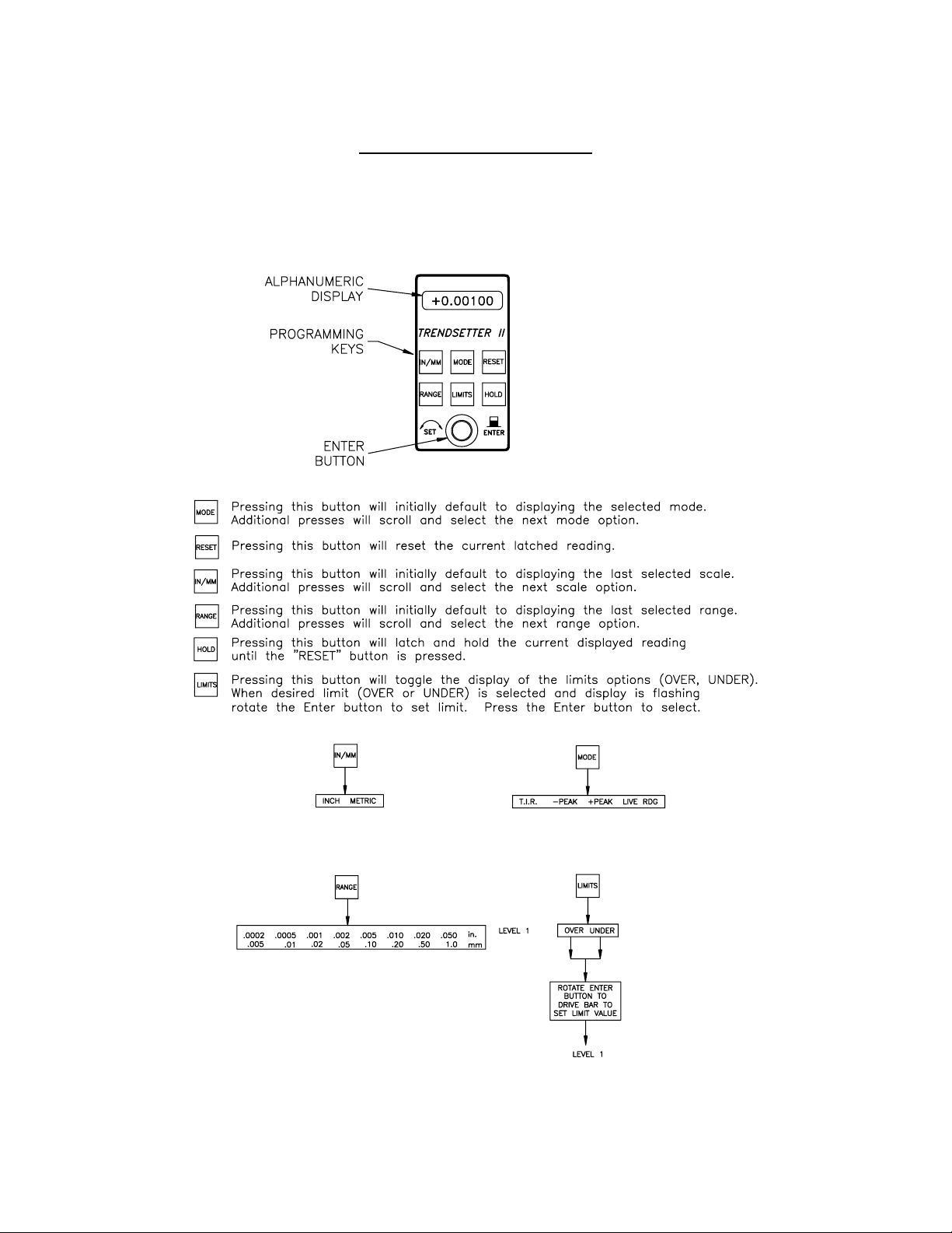
Programming Reference Guide
The following reference guide briefly outlines the functions of the programming buttons
for the Trendsetter II.
Figure 1.1
1-6
System Description
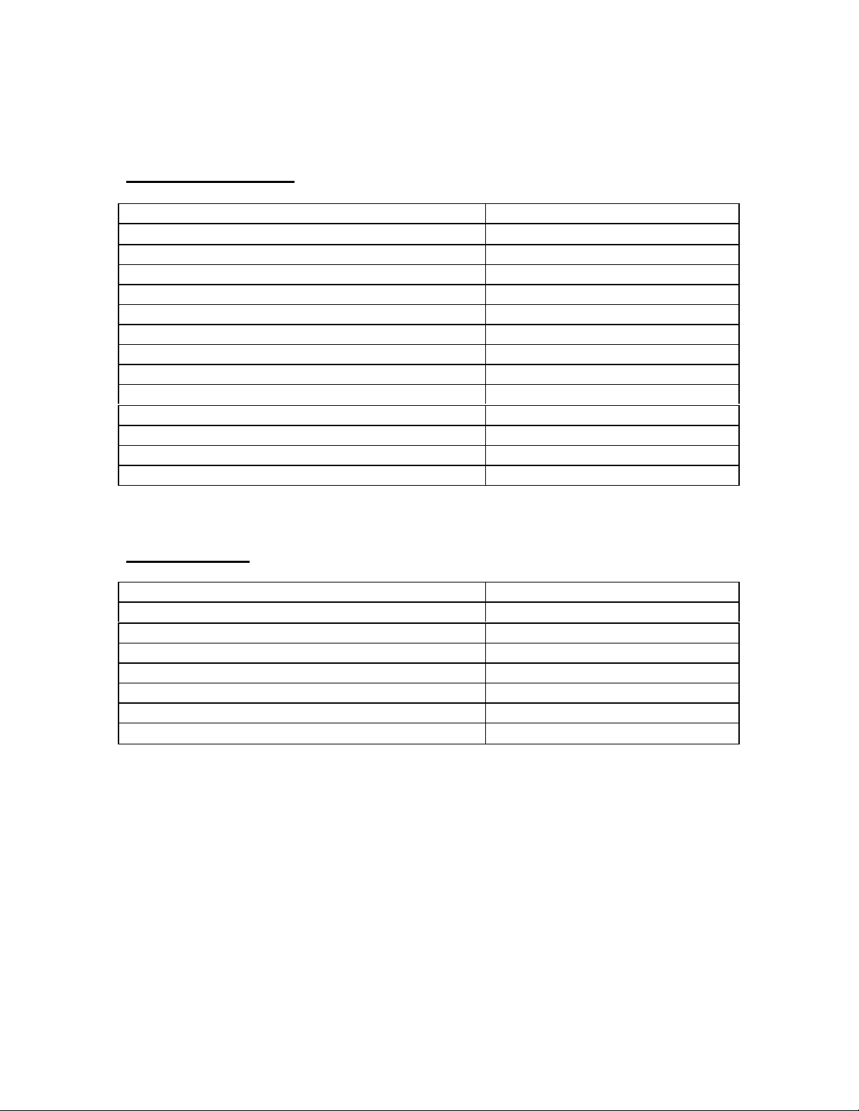
2.0 Number References
Component Edmunds Gages Number
Basic Trendsetter II Unit
(2) Channel LVDT Signal Conditioning Module E8302
(1) Channel A/E Signal Conditioning Module E8303
Power Cable 4550111
Air Filter/Regulator Assembly 5801302
Interface Cable 4550200
Printer Cable 5809060
Power Jumper Cable 4550120
I/O Accessory Board (Optional) 5911013
Auto Air Shutoff Kit (Optional) 5912250
Includes: Valve Assembly 5911200
I/O Accessory Board 5911013
Shutoff Cable 5911018
E8300
2.1 Specifications
Overall Dimensions 21.25” x 2.50” x 9.00”
Power Requirements 100 VAC to 240 VAC 50/60 Hz
Power Consumption 12 Watts @ 120 VAC, 100 mA
Air Requirements (E8303 Module Only)
Pressure 60 psi
Flow Rate 1.6 scfm/air tooling nozzle
Environmental Operating Conditions
Max Temperature
50°C/120°F
2-1
2.2 Recommended Spare Parts
Below is a list of recommended spare parts for the Trendsetter II. These items may be
ordered separately from Edmunds Gages, they are not included with the basic unit.
Part Edmunds Gages P/N Qty.
Basic Unit
10 Amp Fuse 4190135 2
Limit Pointer Assembly 5809508-BM 2
E8302 LVDT Module
2 Position Shunt, .100 Spacing 4570117 1
E8303 A/E Module
A/E Block 3101500 1
Needle Valve Assembly 3101045 1
O-Ring, Restriction Screw 5900026 1
O-Ring, Body 5900027 1
Bias Restrictor Assembly 3101188-B 1
Filter Disc 3101130-B 2
Bias Restrictor O-Ring 5900026 2
Transducer O-Ring 5900043 2
Air Filter Replacement Element SMC #KT-AF2000-5B 1
2 Position Shunt, .100 Spacing 4570117 1
2-2
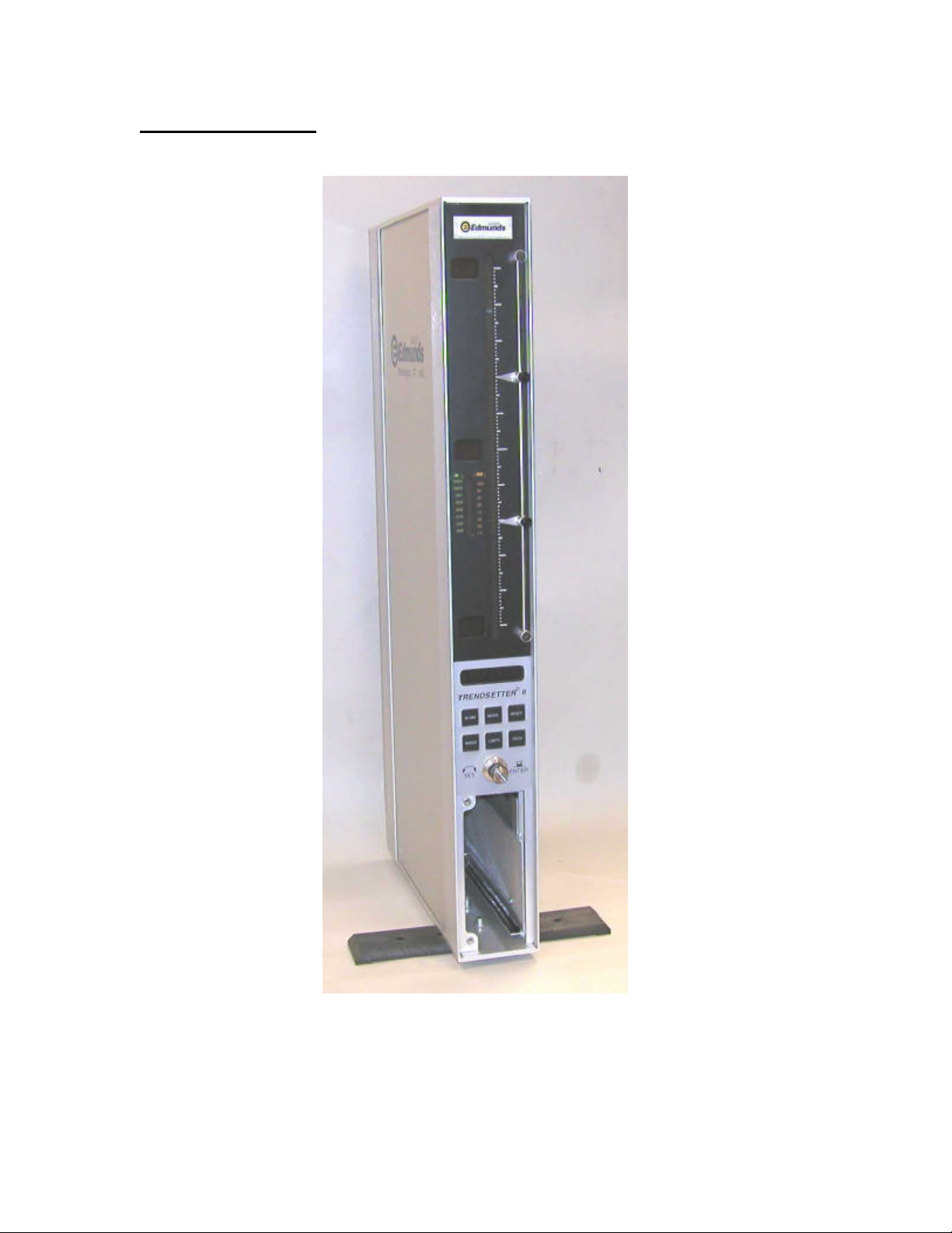
2.3 Overall E8300Unit
Figure 2.1 - Trendsetter II Basic Unit
2-3

2.4 Front Panel
The Trendsetter II front panel consists of the following items:
Bargraph display - The 10 inch, 101 point, three color LED bargraph display is the
primary readout for the Trendsetter II. When over and under limits are programmed, the
bargraph will change colors to visually indicate over (red), under (yellow), or good parts
(green).
Range Annunciators - Located next to the bargraph, the half scale indicators display the
bargraph values for the various ranges.
Adjustable Limit Pointers - Mechanically positioned limit indicators.
Range Indicator - Displays the currently selected full scale range. Inch ranges are
displayed in green. Metric ranges are displayed in amber.
Alphanumeric Display - During gaging operation the alphanumeric display provides a
digital readout of the bargraph value. During programming the alphanumeric display
shows information on the current programming selections.
Programming Keys - Provide a shortcut to the various programmable options.
Rotary Enter Button - The enter button can be either pressed or rotated and is used
during the programming of the Trendsetter II.
2-4

Figure 2.2 - Front Panel
2-5

2.5 Rear Panel
The Trendsetter II rear panel contains the following items:
Serial Number - The Edmunds Gages serial number is listed at the top of the rear panel.
Fuse Locator - Contains a 10 Amp fuse.
Power Switch - Use to switch the unit on or off.
Power Connector - Plug the power cable (Edmunds #4550111) into the power connector
and connect to input line voltage from 100 to 240 VAC at 50 or 60 Hz. The Trendsetter
II contains a universal power supply that will automatically adjust to any line voltage in
the above range.
Power Outlet Jumper - In a multiple Trendsetter II setup, plug power jumper cables
(Edmunds #4550120) from the power outlet jumper on one unit to the power connector
on the next unit.
RS-232C Connector - Use to output gage results to an external data collector.
IN/OUT A (25 Pin) - Use to input/output parallel and analog signals from another
Trendsetter II or to an external device using interface cable, Edmunds #4550203. See
figure 2-3 for pin assignments.
IN/OUT B (25 Pin) - Use to input/output parallel and analog signals from another
Trendsetter II or to an external device using interface cable, Edmunds #4550203. See
figure 2-3 for pin assignments.
44 PSI Inlet - When the air to electric module is installed in the lower bay, an air hose
fitting will extend out the 44 psi inlet port on the rear of the Trendsetter II. An air line is
connected to this fitting and to the outlet side of the air filter/regulator assembly.
2-6
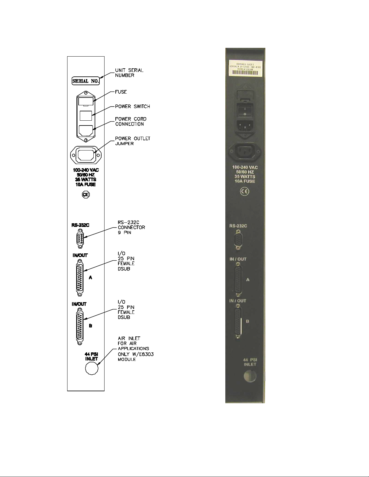
Figure 2.3 - Rear Panel
2-7
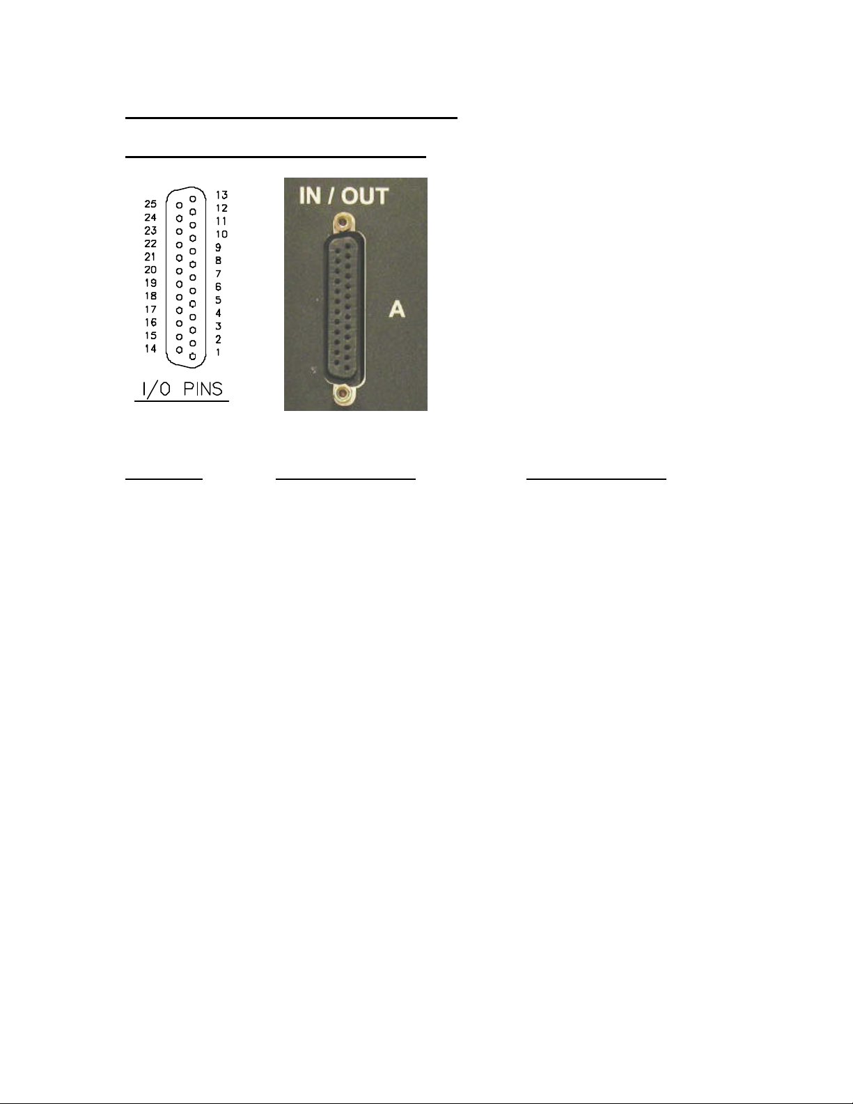
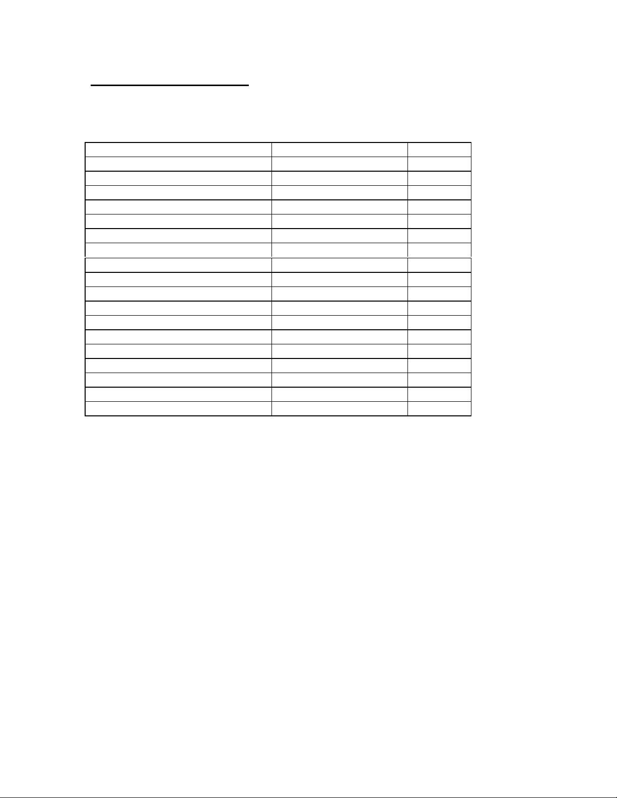
2.6 Pin Assignments for Rear Panel connectors
In/Out A, In/Out B (25 Pin Female DSUB)
Figure 2.4 - I/O Pins
Pin Number IN/OUT A Description IN/OUT B Description
1 Analog Out 1 “
2 Analog Out 2 “
3 Analog Out 3 “
4 Analog Out 4 “
5 Analog Out 5 “
6 Analog Out 6 “
7 Air shut off present (Input) “
8 **Spare 1 (Input) “
9 Air off (Output) “
10 **Spare 2 (Output) “
11 AGND “
12 **Over Relay (Output) “
13 **Good Relay (Output) “
14 **Under Relay (Output) “
15 **Write/Disable (Input) “
16 **Reset (Input) “
17 **Footswitch (Send Data/Input) “
18 NC +V (External Switch)
19 **Relay Output Common “
20 **TIR Reset (Input) “
21 **Reserved Output “
22 **Reserved Output “
23 **Reserved Output “
24 **Isolated Common “
25 NC High Level Analog Out
• NC = Not connected
• Reserved pins should be considered “Do Not Connect”
• ** Functions available with optional I/O board #5911013
2-8
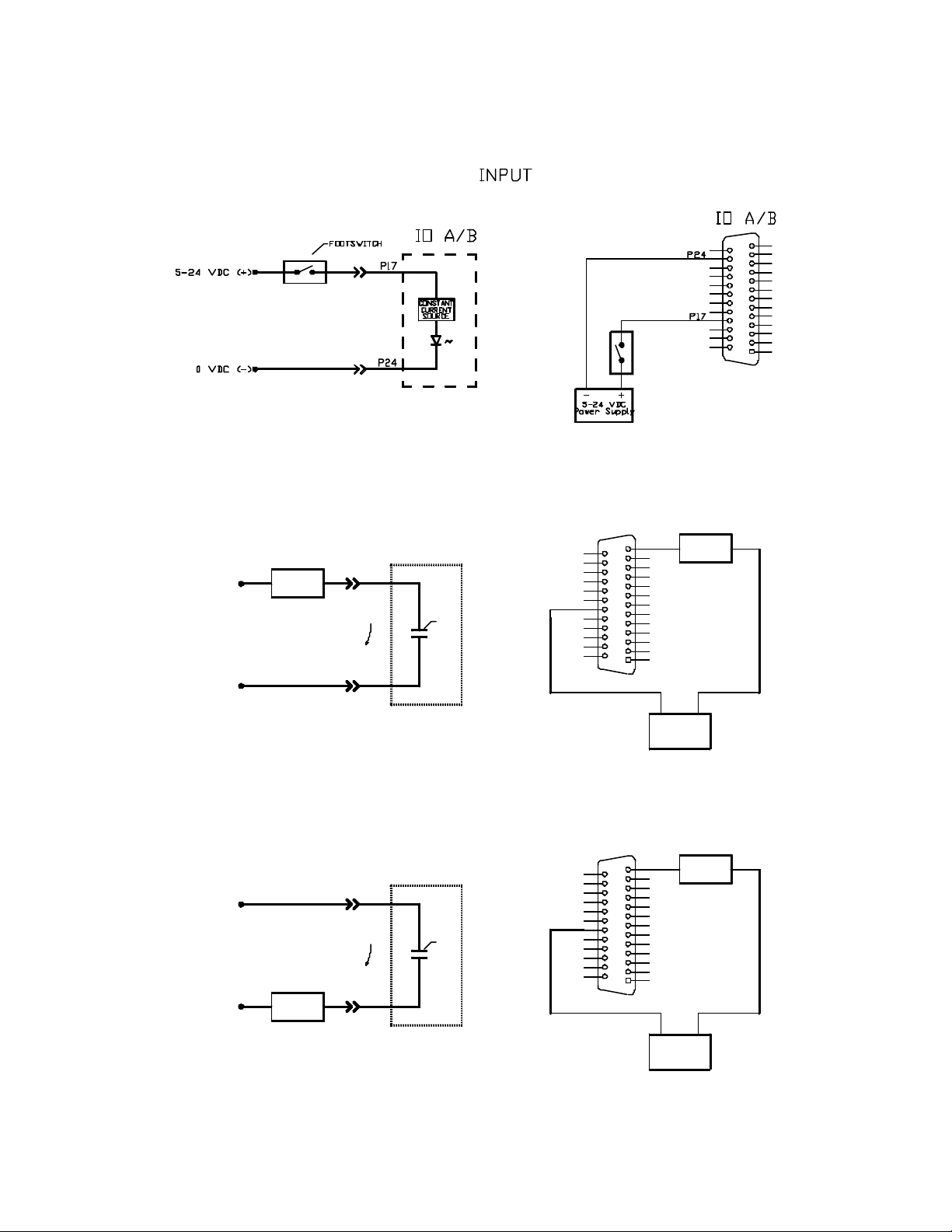
Typical IO Connections - Optional I/O Board #5911013 Required
OUTPUT "SINKING"
IO A/B
IO A/B
P13
LOAD
+24 VDC (+)
0 VDC (-)
+24 VDC (+)
0 VDC (-)
LOAD
LOAD
CURRENT
FLOW
CURRENT
FLOW
P13
GOOD
RELAY
P19
OUTPUT "SOURCING"
IO A/B
P19
GOOD
RELAY
P13
P19
+-
24VDC
Power Supply
IO A/B
P13
LOAD
P19
2-9
24VDC
Power Supply
-+
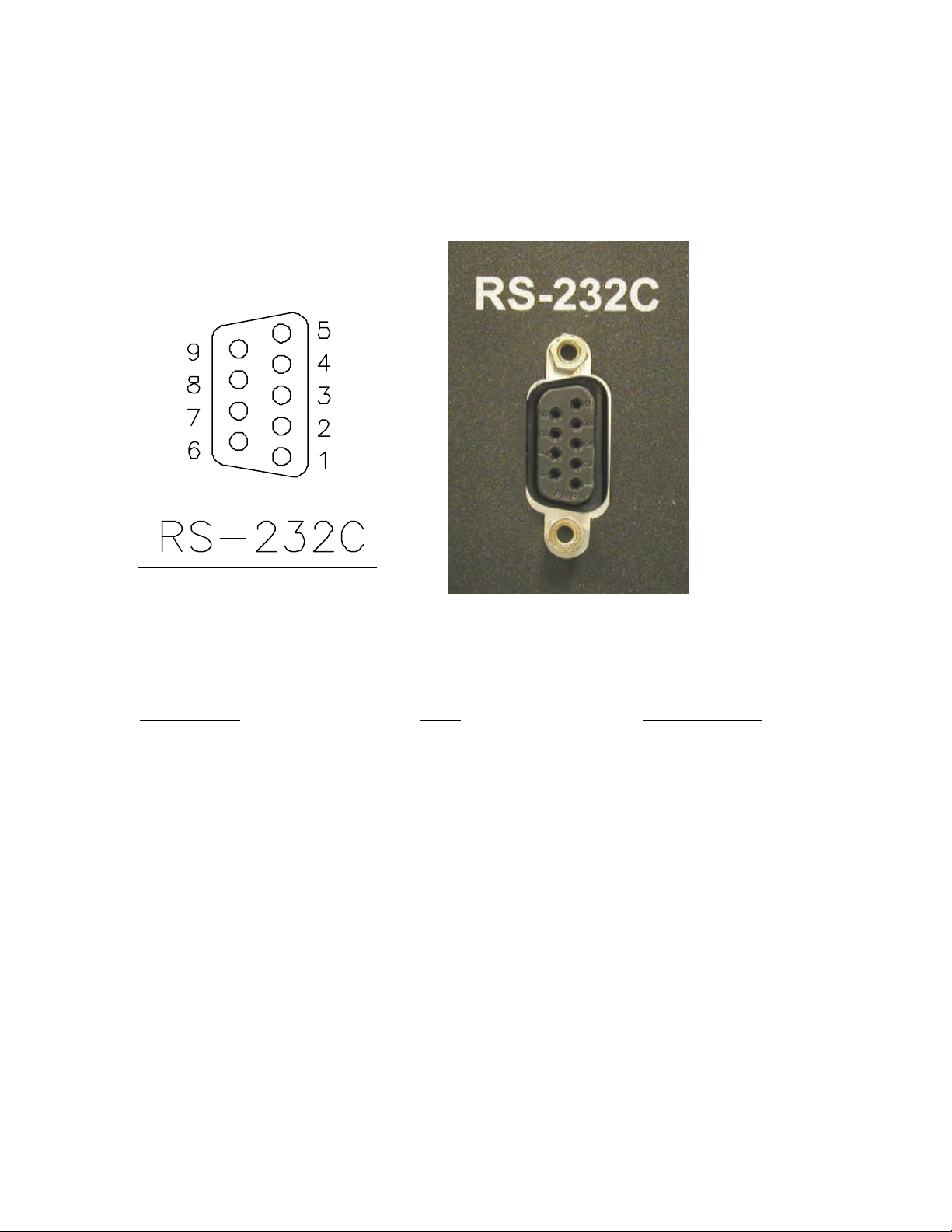
RS232C (9 Pin Female DSUB)
Figure 2.5
Figure 2.6 - RS-232C Pins
Trendsetter II Cable External Device
Pin 1 = Chassis Ground. ß----------------------------à Chassis Ground.
Pin 2 = Receive (RXD) ß----------------------------à (TXD) Transmit.
Pin 3 = Transmit (TXD) ß----------------------------à (RXD) Receive.
Pin 5 = Signal Ground ß----------------------------à Signal Ground.
Note: Pin2 and 3 are jumper selectable based upon the application.
2-10

2.7 E8302 (2) Channel LVDT Signal Conditioning Module
The E8302 module is a two-channel signal conditioning amplifier for inductive type
transducers such as LVDTs that converts the outputs of the transducers into a conditioned
signal for the main controller board. The module is mounted in the lower bay of the
Trendsetter II.
The polarity of inputs A and B must be setup using either switches on the original version
of the board or jumpers on the current version of the circuit board. The polarity setting
determines whether the input reads positive or negative when the LVDT tip is depressed.
The input magnification must also be set using jumpers allowing magnification reduction
to be set to 10x for long range transduc ers or 1x for standard transducers.
A jumper matrix on the board allows it to accept signals in or send signals out to the
analog output connector. By placing the jumper pin for the desired signal line on one of
the six buss lines, the signal can now be sent or received by any other units connected to
the buss.
The bussed in signals, C and D, can be added or subtracted using the "SUM/DIFF"
jumpers.
The LVDT module contains a INPUT selection knob. The INPUT selection knob can be
set to A, B, or AB. When set to A the reading of only input A will be displayed on the
bargraph and the alphanumeric display. When set to B the reading of only input B will
be displayed on the bargraph and the alphanumeric display. When set to AB the result of
input A + input B will be displayed. Note: When auxiliary inputs C and/or D utilized,
they will be "summed" together with LVDT inputs A and B.
The LVDT signal conditioning module also contains a ZERO adjustment knob for inputs
A and B, a MAG adjustment screw for the A and B inputs, and a MAG adjustment screw
for inputs C and D bussed in from a separate column or columns.
Power to the column must be turned off prior to installing or removing a signal
conditioning module.
Refer to the Advanced Operation, LVDT Module Setup section for additional
information on jumper settings and see Basic Operation, Setting LVDT Mag & Zero
for additional information on setting Mag and Zero for a particular application.
2-11
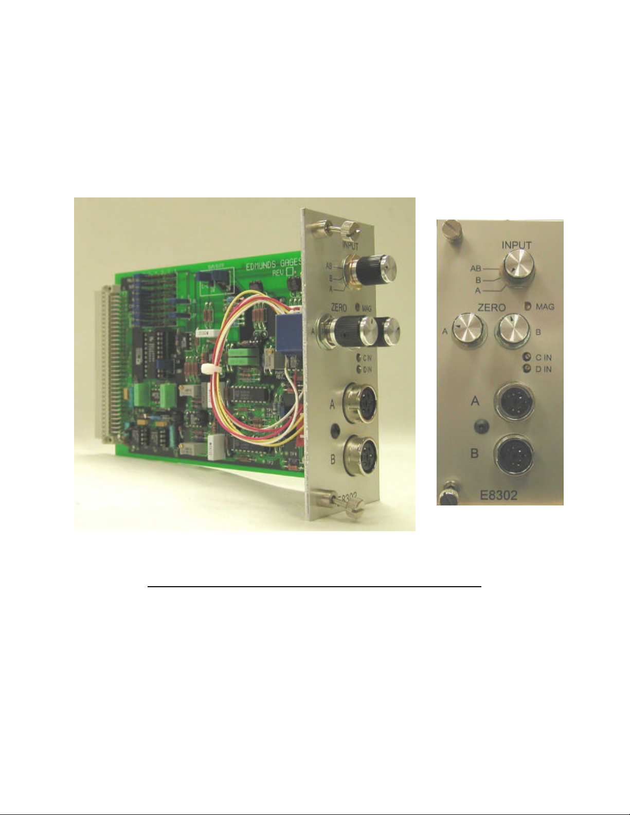
Figure 2.7 - E8302 (2) Channel LVDT Signal Conditioning Module
2-12
2.8 E8303 (1) Channel A/E Signal Conditioning Module
The E8303 module is a single channel air/electric amplifier which processes pneumatic
information from the air tooling and delivers a conditioned signal to the controller board
of the Trendsetter II. The module is mounted in the lower bay of the Trendsetter II.
The A/E module also contains a ZERO adjustment knob and a MAG adjustment knob for
initial input setup to accommodate the air tooling used..
The air tooling is connected to the air fitting on the front panel of the module. The
recommended length of air line from the module to the air tool is no more than six feet.
A minimum of 60 psi air must be supplied to the filter/regulator assembly on the rear of
the unit. The regulator is factory set to 44 psi.
The polarity of the input must be setup using jumpers on the circuit board. The polarity
setting determines whether the input reads positive or negative when the air nozzles are
closed off. The input gain must also be set to low, medium, or high use jumpers supplied
on the circuit board. A jumper strip labeled "A OUT" provides the option to select a pin,
1 -6, to output a high level (+/-1.84VDC) signal to the I/O connectors.
Power to the column must be turned off prior to installing or removing a signal
conditioning module.
Refer to the Advanced Operation, A/E Module Setup section for additional
information on jumper settings and see Basic Operation, Setting A/E Mag & Zero
for additional information on setting Mag and Zero for a particular application.
2-13
 Loading...