

Edmunds TRENDSETTER Instruction Manual
INSTRUCTION
MANUAL
EDMUNDS GAGES
FARMINGTON INDUSTRIAL PARK
FARMINGTON, CT 06032 USA • (860) 677-2813
FAX (860) 677-4243
Edmunds
TRENDSETTER
™
GAGES
Edmunds

TRENDSETTER™
Ever since it’ s emergence in 1977, the T r endsetter™ gaging column has been the most reliable and
technologically advanced column gage in the world. With both electric and air-to-electric capabilities, the Trendsetter™ is on the cutting edge of component and design technology while continuing
to provide the user -friendly ease you’ve come to expect fr om all Edmunds pr oducts.
The overwhelming success of the Trendsetter™ reflects a company-wide commitment to continual
technological improvement, technical integration, and customer satisfaction. This unique gagingcolumn has been, and will continue to be, a dynamic and evolutionary technological achievement;
a reliable and responsive instrument perfectly suited to a constantly changing gaging environment.
EDMUNDS GAGES
Farmington Industrial Park
Farmington, CT 06032 USA
Tel (860) 677-2813
Fax (860) 677-4243
2

TABLE OF CONTENTS
Page
1. Introduction ................................................................................................................... 2
2. General Description
2-1 Electronic Gaging
2-1.1 Preparing For Use........................................................................................ 4
2-1.2 Operation with LVDT Cartridges................................................................. 5
2-1.3 Mastering..................................................................................................... 5
2-1.4 Front Panel Magnification Adjustment........................................................ 5
2-1.5 Main Mag Adjustment ................................................................................. 6
2-1.6 Balance ........................................................................................................ 6
2-2 Air/Electronic Gaging.............................................................................................. 7
2-2.1 Preparing For Use........................................................................................ 7
2-2.2 Setting the Air Reading................................................................................ 8
2-2.3 Mastering..................................................................................................... 9
2-2.4 Setting to Tooling other than Edmunds..................................................... 10
3. Technical Description
3-1 E8000 Main Frame Assembly.............................................................................. 11
3-2 E8001 Limit Light Module 3 Point........................................................................ 14
3-3 E8007 Multipoint Classifying Module .................................................................. 16
3-4 E8011 Limit Light Module 5 Point........................................................................ 18
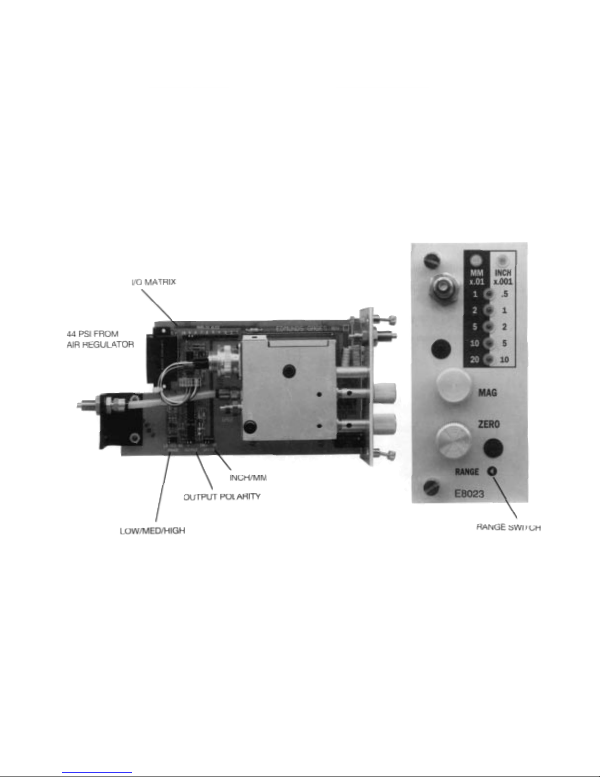
3-5 E8023 Air/Electronic Module................................................................................ 20
3-5.1 Air/Electronic Maintenance....................................................................... 22
3-5.2 Block Diagrams E8023.............................................................................. 24
3-6 E8024 T.I.R. Module with Limit Lights................................................................. 25
3-7 E8026 Sum & Difference Module......................................................................... 29
3-7.1 Block Diagrams E8026.............................................................................. 32
3-8 E8032 (2) Channel LVDT Module......................................................................... 33
3-8.1 Block Diagrams E8032.............................................................................. 35
3-9 E8051 Strain Gage Module.................................................................................. 36
3-9.1 Block Diagrams E8051.............................................................................. 38
3-10 E80124 High Speed O.D. Module ......................................................................39
4. Trendsetter™ System Programming........................................................................... 41
4-1.1 Trendsetter™ Programming Diagram .............................................................. 43
4-1.2 Trendsetter™ Systems Programming.............................................................. 44
5. Matrix Pin Header Programming................................................................................. 45
5-1.1 Programming Example-Clearance Comparator............................................... 45
5-1.2 Programming Example-Squareness/Taper...................................................... 46
6. Accessories
6-1 E8204 Relay Interface Cabinet............................................................................. 49
3
EDMUNDS TRENDSETTER™
2.1 ELECTRONIC GAGING
2-1.1
Preparing For Use - Electronic Gaging
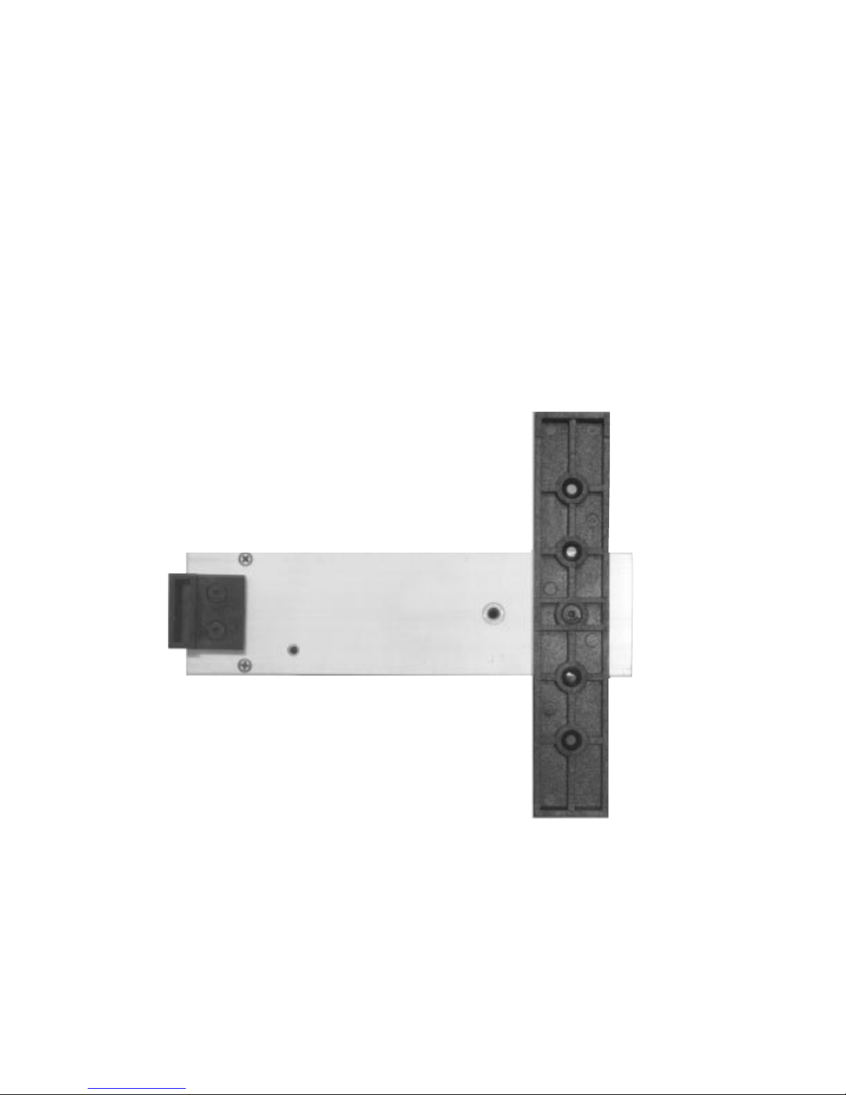
This opening description will be as brief as possible in an effort to minimize setup time. A mor e
complete description of the column and it’s modules will be found later in the manual. To form a
firm three point support for the column, unscrew the front screw at the bottom of the long foot and
remount the foot on the front scr ew. The foot should be perpendicular to the column. This foot
will also serve as a connector for multiple column setups.
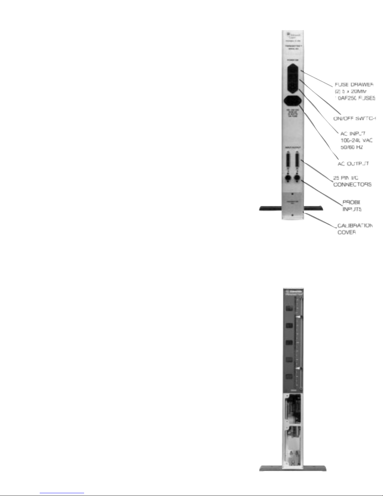
With the power switch off, plug in one or two gage probes into the A & B input sockets located in
the rear of the column. Next, plug in the 100-240 VAC/50-60 Hz supply to the back of the column.
4

2-1.2 Operation of T rendsetter™ with LVDT Electronic Probes
Using the power switch located at the rear of the column, turn the unit on. Depending upon your
application, select the input channel as required: A, B, or AB. Next, check the Inch, Metric, indicator light to see if the gage is set to the required measurement system. Depress the contacts on the
probe to see if the column moves in the correct direction for the movement of the contacts; i.e., for
an O.D. measurement, a large part will cause the probe tip to move in. Any depr ession on the pr obe
tip should move the bargraph display in an upward direction. If either of these functions is incorr ect,
remove the module as follows: switch the column off, unscrew the two module retraining scr ews,
and gently pull the module out. Do not touch the matrix I/O pin headers; the function of these units
can be found later in this write-up.
Check that the Inch and Metric Pin Headers as well as the polarity switches are in their correct
position. Replace the module by lining up the top and bottom edges of the board with it’s card
guides and sliding back until it locates in its electrical socket. Screw in the two module retaining
screws to secure the module and switch power on. The full scale range of the readout should now
be set.
To select a range, if it has not already been decided, it is best to select one that is two to three
times greater than the tolerance being checked. This will allow for good approach and oversize
range. If parts are being matched or segregated into classes and are all in tolerance, much more of
the full scale range can be used.
Set the range knob to the desired value. The corresponding digital scale values will be shown
alongside the bargraph scale. The setup is now ready for mastering.
2-1.3 Mastering
There are two basic approaches to mastering:
1.) Min. and Max. masters
2.) Mean or zero master
Setting to a Mean Master
Place the mean master in a fixture and turn the zero knob to bring the scale to zero or to the actual
calibrated size of the master.
Setting to Min. & Max. Masters
Place the max. master in the gage and, with the zero knob, adjust the column to the upper limit
reading. Remove the max. master and replace with the min. master. The reading should rise to the
lower limit. If, due to a poor initial calibration (or a non 1:1 ratio in the lever arms of the gage), the
lower limit is not achieved, the magnification should be altered.
2-1.4 Front Panel Magnification Trim
Place one master in the gage. Set one limit at the desired point with the zero knob. Apply the other
master and, with a small screwdriver, adjust the recessed “mag” screw until the column moves to
the desired point. Reapply the other master and, if necessary, readjust until both masters move the
column the required amount. This front adjust scr ew will allow for a trim of appr oximately 20% and
will change all inputs; A, B, and AB.
In some cases, where transducers other than Edmunds’ gage probes are being used, or where
levers change the 1:1 ratio of input to output, the rear adjustments on the circuit board may need to
be used.
5

To insure the success of your mastering procedur e and the stability of the gage, the set points
should be re-checked with the masters at frequent intervals. The need for constant mastering will
decrease as the Trendsetter™ and the gage demonstrate stability and repeatability. Frequent mastering will ensure that there are no loose contacts, and that the system is not experiencing any drift.
These potential failures can be found only by frequent mastering under production conditions.
2-1.5 Main Magnification Adjustment
At the lower back of the column is an inspection panel held in position with two screws. Removal of
this panel will expose calibration trim pot screws labeled Cal. A and Cal. B. Each input should be
set independently , using some basic measuring means such as a micr ometer drive, gage blocks, or
if a single probe is being used in the fixture, this may be used with the master or with shims. Switch
to Channel A on the front of the column and set probe A to its low limit. Adjust the front zero knob
to the low column reading.
Move the probe tip the mastering distance by one of the described methods and turn the Cal. A pot
to bring the column reading to the high position. Re-check, and if, necessary, repeat between master points to obtain the desired column movement between min. and max. master positions.
Repeat this procedure for probe B with the fr ont panel switch turned to Channel B. With both A & B
set for magnification, replace the rear inspection panel. If both probes ar e being used as A & B, turn
to Channel AB and do any final master trimming on the front pot as previously described.
2-1.6 Balance
One final word on calibration is the concept of balance. Balance is the final “trimming out” of all
system magnification errors. It should be noted that balance only concerns differential measurements; when both probes are measuring a diameter for example. Also, lack of balance is one of the
chief causes of poor system repeatability.
Balance is easily achieved and observed by the use of a simple mechanical balancing fixture. The
fixture clamps the A and B probes in opposing positions, and with the use of a micrometer, moves
the probes in exactly equal, but opposite directions. Such a fixture is available through Edmunds
Gages as BG29412. To check balance, complete the calibrations as described in the previous sections. Mount the A and B probes in the balancing fixture. Adjust each probe to its mechanical zero
as observed on the Trendsetter™ bargraph display. Then with the range switch set to desired application range, and the polarity/function switches set to A+B mode, rotate the micrometer head
some convenient distance. This distance should not exceed 2x the selected range. Observe the
bargraph, it should remain fixed at zero under these conditions. If, for example, the Trendsetter™ is
set to the 0.005 inch range and the micrometer head is rotated thru 0.010 inch, the bargraph should
remain exactly at its zero position. Any movement observed on the scale indicates the system is
out of balance.
To achieve balance, a magnification adjustment is required to one channel only. First, reset the system back to its zero starting point. Next, offset the micrometer head and adjust the B channel mag
through the rear cover. The initial amount of adjustment should be small, say no more than 1/4 turn
on the B mag pot.
Observe the bargraph, did the error get gr eater or smaller? If greater, turn the mag pot in the opposite direction. If smaller, adjust the pot in the same direction until the bargraph remains on zer o, with
the micrometer rotated thru its range. To achieve a greater degr ee of balance, increase the systems
sensitivity via the range switch. With a little practice and patience, balances in the order of 25
microinches or less are easily obtained!
6
When no further balance can be obtained from the system, restore the system to its initial state.
Using masters, recheck the systems mag and zero. If magnification requir es adjusting, use the fr
ont
panel mag pot only, as any rear panel adjustment will nullify the balance procedure.
Balancing in a Gage Fixture
Balance may also be obtained in a gage fixture. The procedure is similar to the proceeding section
except the max master and the gage fixture are used in place of the balancing fixture.Place the max
master in the gage fixture, adjust the Trendsetter™ display to zero, push the master in a direction
which is parallel to the plane that the gage probes are mounted in. The Trendsetter™ readout
should remain fixed at zero. If any movement is observed, adjust one rear panel mag pot as
described in the preceding section. Repeat the procedure several times until no movement is
observed on the Trendsetter™ display . Restor e the system to its original settings, and recheck calibration with max/min masters. Remember to use the front panel mag only, as any further rear panel
adjustment will nullify the balance procedure.
2.2 AIR/ELECTRONIC GAGING
2-2.1
Preparing For Use - A/E Gaging
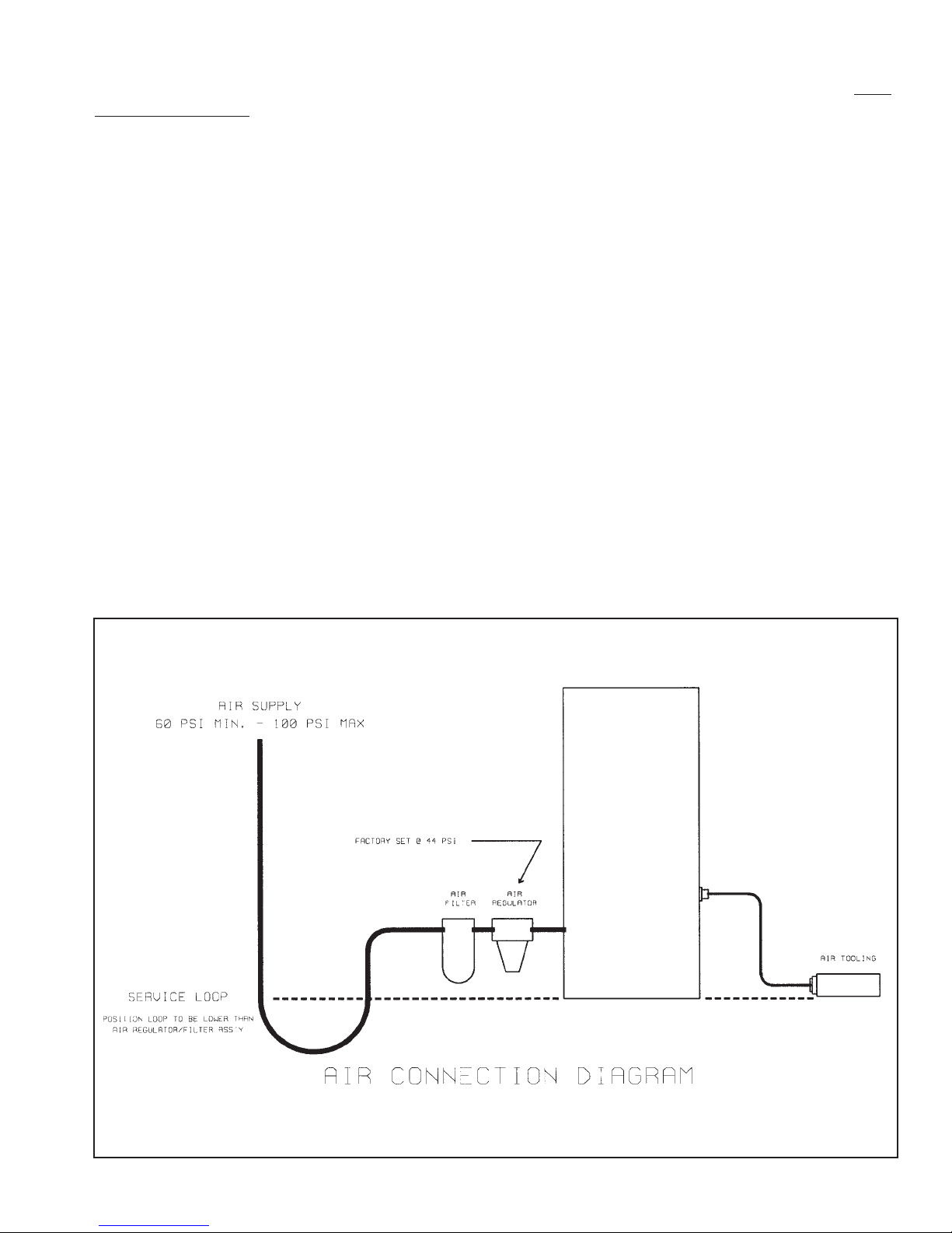
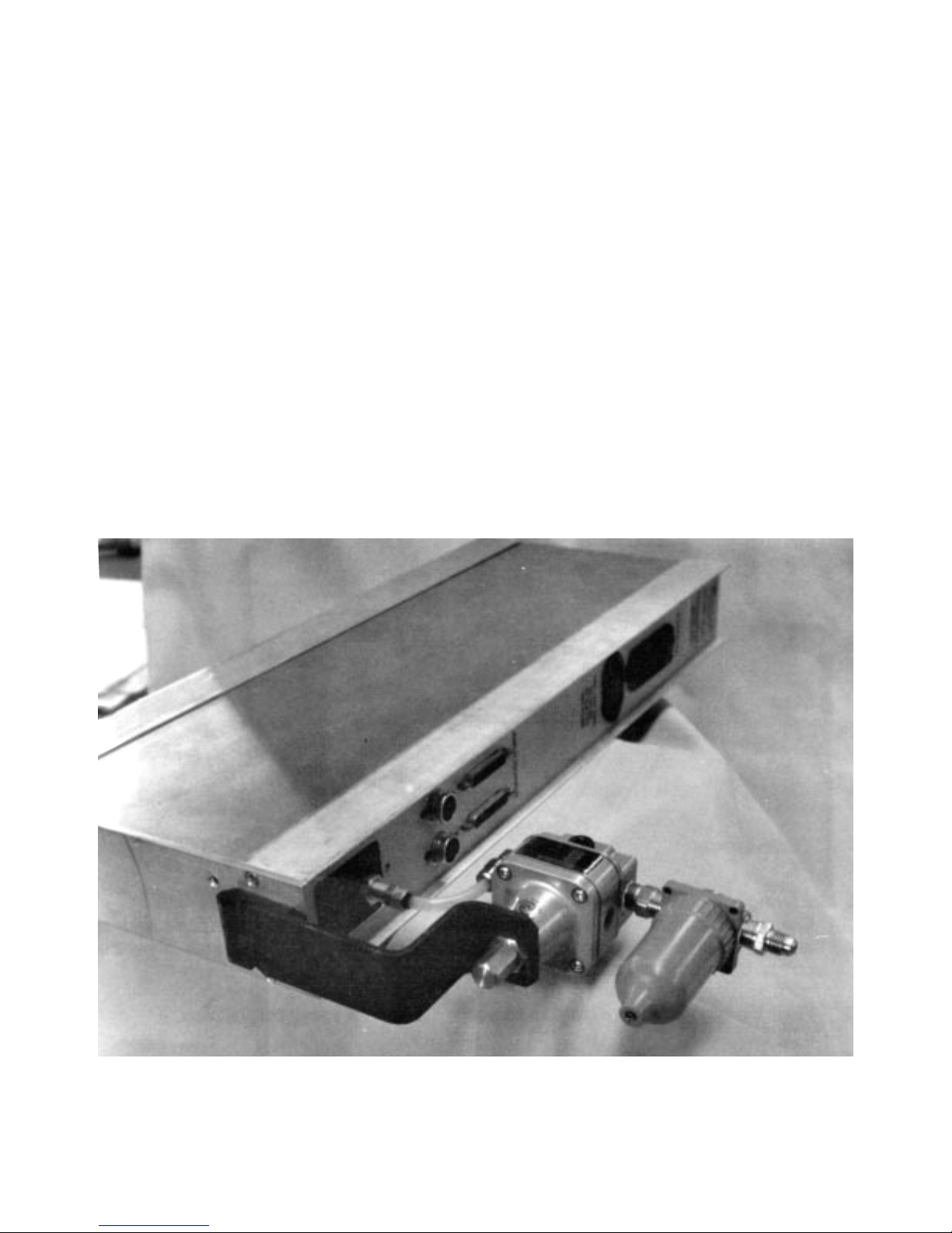
Before operation, the front foot should be set at 90° to column as described before. The air regulator and filter should be mounted on the column. Unscrew the two screws holding the back foot and
turn 180° allowing the regulator and filter bracket to be mounted as shown. See photo on page 8
for correct installation.
Connect the short hose from the regulator output connector to the hose connector labeled 44.
Next, couple the tooling hose to the front gage connector. Be sure that the small plastic sleeve is
positioned correctly to insure a good seal clamp on both hoses. Tighten the brass nuts.
7
Connect the main air supply (60 PSI min) to the filter input. A turn off valve or a quick disconnect
should be used for this connection to enable the air line to readily be disconnected from the column. Connect the readout power connector to 100-240 VAC/50-60 Hz supply. Turn the power on,
turn the air supply on.
Air Consumption
Typical air consumption for Edmunds tooling is as follows; 1.50 CFM per nozzle with the air tool
inserted into a working piece part or 1.67 CFM per nozzle when the air tool is vented to atmosphere.
2-2.2 Setting the Air Reading
The air unit has three air amplification ranges: low , medium and high. It can be run in inch or Metric
units with the high and low readings either at the top or bottom of the scale. The pin headers to
control these functions are located on the A/E module and are not r eadily accessible to the operator. To gain access to the air amplification, inch/metric, and polarity pin headers, the module should
be removed with the main power switch and air supply turned off.
1.) Remove both air lines from regulator and tooling.
2.) Unscrew the two front panel screws and car efully pull
the module out.
3.) Select the proper headers and reinsert the module.
All Edmunds air tooling is marked with the full scale range for which it is intended to operate. Since
overall range of air gaging is limited, the tooling is designed to operate on one scale only.
8
Unauthorized switching of ranges may affect the performance and linearity of the tooling. The tooling should be used with the following magnifications:
Marked Range Air Amplification
.010” /0.2mm Low
.005” /0.1mm Low
.002” / .05mm Med
.001” / .02mm Med/High
.0005”/ .01mm High
To set the range of the module on the bargraph, turn the front panel range switch to required position using a small screwdriver inserted thru the front panel.
2-2.3 Mastering
1.) Check the two master sizes and determine the set points on the bargraph scale. With an
air plug, the smaller size is on the bottom. Set the pointers on the side cursor to the 2 set
points. Usually this will be with zero in the middle.
2.) Place the large-sized, or maximum ring gage master over the air plug nozzles.
3.) Adjust the top knob (M) to align the column with the to pointer.
4.) Place the minimum ring gage master over the air plug nozzle.
9

5.) Note carefully the deviation between the column position and the minus (“-”) pointer position. Adjust bottom knob “Z” so that the column passes the minus (“-”) pointer and overcorrects by a distance approximately 3 times the deviation just noted when using low
amplification.
NOTE: Medium amplification has a correction factor of 10 times. High amplification has a
correction factor of 30 times.
6.) Adjust the top knob “M” to align the column with the minus (“-”) pointer.
7.) Repeat steps 2 to 6 until the maximum and minimum ring gage masters bring the column
in line with the plus (“+”) and minus (“-”) pointers, respectively.
If the module has limit lights, adjust the Cal. high and Cal. low to the set points. These may also be
used instead of the cursor points and should be preset before mastering the gage for ease of
setup. (See
Setting Limit Lights.)
2-2.4 Setting to T ooling other than Supplied by Edmunds
The Trendsetter™ will operate with just about any brand of air tooling, regardless of the system for
which such tooling was originally designed. Use of the Trendsetter™ with tooling manufactured for
a type of system other than Edmunds, may require some trial and error to determine the best air
amplification choice for the most stable and linear readings.When tooling (from another system) is
being used with the column, the scale and magnification must be altered to suit that particular
tooling.
Flow system tooling, which has a very shallow nozzle drop, will show very high magnification when
used on a Trendsetter™. This might necessitate a change to a lower air amplification on the 3 range
pin header.
Differential type tooling will show a slightly lower magnification than the restriction bleed tooling,
and may possibly require a high air amplification setting.
To setup these types of tooling, the following steps should help: gently close off the zero “bleed”
knob and mag restriction knob; taking care not to screw in too tightly. With the max. master on the
tooling, the column should be off scale at the bottom or top, depending on I.D. or O.D. readings.
Slowly unscrew the mag knob until the column comes on scale. Stop at the mastering point on the
scale. The gage has been set to its highest possible magnification for this tooling. Replace the max.
master with the min. The column will move to a new position. If it is not at the min. mastering point,
the magnification is not sufficient for this setup. In this case, shut the unit down, turn off air and
electric supply , r emove the module and switch to the next higher air amplification using the range
pin header.
The maximum that either knob can be unscrewed is approximately five turns before the system
becomes unstable. This may occur before, depending on the air flow required to operate the tooling, and will be clearly shown by column instability . None of these situations will occur when using
normal restriction bleed type tooling, as provided by Edmunds. The air circuit is completely compatible with Edmunds E series air gages.
10
3.0 DET AILED DESCRIPTION
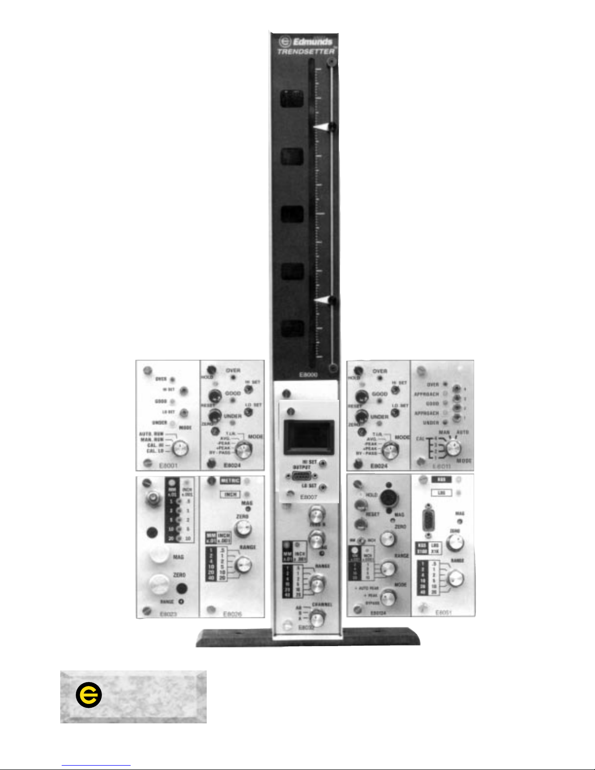
E8000 - MAIN FRAME ASSEMBLY
3-1 Functional Description - Rev. D.
The E8000 Main Frame Assembly is the focal
point for the various plug in modules associated
with the Trendsetter™ system.
The Main Frame provides mechanical support,
interface wiring, I/O connections, power supplies
and a bargraph readout.The Main Frame measures 21.25” high, 2.50” wide, 9.00” deep.
Cabinet construction is aluminum.
An internal power supply generates +/- 15 VDC
regulated at +/- 1 AMP, and + 5 VDC at 3.0
amps. These voltages drive the display board
electronics, and any combination of plug in
modules.
The power supply is of the universal type, in that
it automatically adjusts to any line voltage from
100 VAC to 240 VAC, 50/60 Hertz.
Power consumption is 35 watts maximum. 15
watts is more typical and will drive a full compliment of plug in modules.
A 10 inch, 101 point bargraph display is the primary means of readout. The 101 points give a
readable resolution of 1%. Digital scale readouts
are placed alongside the bargraph display for
ease of interpreting scales. Range switches on
various modules, have encoding logic which
supplies range information to a numeric display
library.
Additionally a 10 position dip switch, located
inside the rear panel and adjacent to the I/O
connectors, provides a simple means for
enabling any lower bay high level output signal
to reach the 10 line analog buss. The dip switch
numbers correspond to user programmable lines
1-10.
Upper Bay Modules
If the gage is to be used without an upper module, a jumper must be installed from pin 13 to pin
15 on the upper 15 pin socket. However, if a
module is to be installed, check that the jumper
is removed
.
11
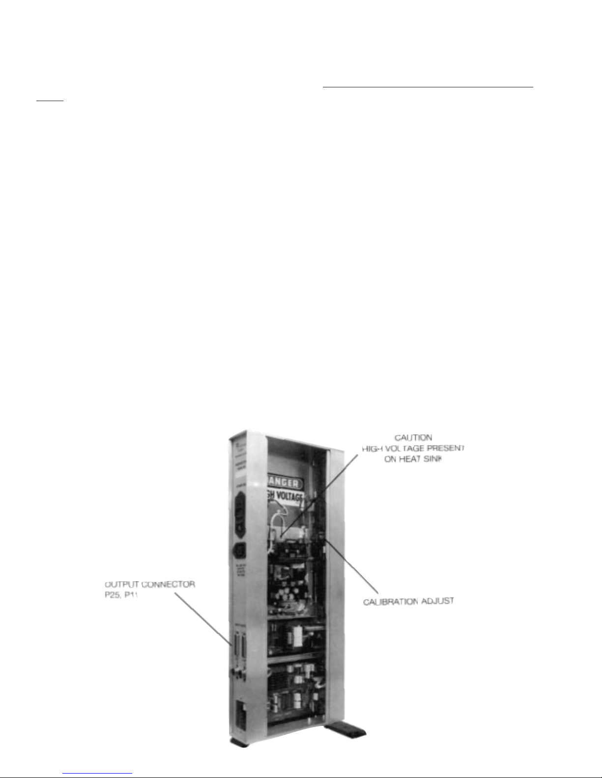
CAUTION! OBSERVE HIGH VOLT AGES PRESENT WITHIN TRENDSETTER™ CABINET
Main Frame Calibration
Calibration consists of furnishing a +/- 2.500 volt input to the display card, and adjusting the gain
pot. Before attempting, remove all plug-in modules, and
observe all high voltage safety precau-
tions.
1. Completely remove all AC power.
2. Facing the instrument, remove the top and left hand side covers.
3. Re-connect AC power.
4. Energize the instrument and allow to warm-up for a period of 5 minutes.
5. Apply + 2.500 volt signal to P25 of output connector, and D.C. common to P11, and
adjust gain pot for full scale.
6. Repeat step 5 with - 2.500 volt, and readjust if necessary.
7. Repeat step 4-6 until +/- full scale and center zero have been set.
Repair
Most integrated circuit components located on the display card are socket mounted for ease of
service. The seven segment digital readouts and bargraph displays are easily r eplaced should a failure occur. To replace these components:
1. Completely remove all AC power.
2. Remove top cover plate.
3. Remove 2 screws holding pointer rail assembly.
4. Slide out plastic display bezel.
5. Unplug connectors. Slide display assembly out of case.
6. Remove faulty component and replace with spare.
7. Re-assemble in reverse order.
12

The Common Buss
On an application that requires the output of a measuring head to be fed into more than one column for adding, averaging, checking clearance, etc., the output signal from the column is fed into a
common buss wired to the 25 pin I/O connectors. A 25 pin connector cable is plugged into each of
the columns and feeds the signal into all columns where it may or may not be used (as required).
See matrix switching and examples.
Rear Panel 25 Pin I/O Connector Assignments
Pin Number Input Connector Output Connector
1 Analog Output 1 "
2 Analog Output 2 "
3 Analog Output 3 "
4 Analog Output 4 "
5 Analog Output 5 "
6 Analog Output 6 "
7 Analog Output 7 "
8 Analog Output 8 "
9 Analog Output 9 "
10 Analog Output 10 "
11 Analog Common "
12 High Output Comparator "
13 Good Output Comparator "
14 Low Output Comparator "
15 Write/Disable "
16 Reset "
17 NC "
18 NC "
19 NC "
20 TIR Reset "
21 NC "
22 NC "
23 NC "
24 Isolated Common "
25 NC High Level Output
NC = No Connection
13
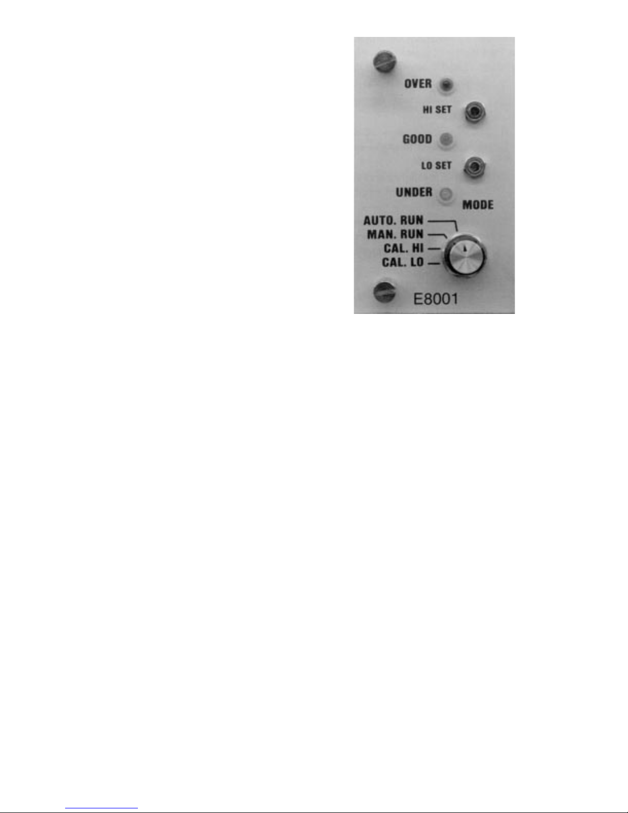
E8001 - LIMIT LIGHT MODULE
3-2
Functional Description
The E8001 limit light module electronically compares a lower bay input signal, against two operator calibrated set points. The E8001 module
sorts the input signal into one of three classes.
1.
Over — Input signal is greater than the
high limit setpoint.
2. Good — Input signal is less than high limit,
greater than low limit setpoint.
3.
Under — Input signal is less than the low
limit setpoint.
High Limit Setpoint
This control pot is located on the front panel and
is adjustable using a screwdriver.
Low Limit Setpoint
Similarly , operator calibration of this contr ol
determines the low limit setpoint.
14
Mode Switch
The front panel mode switch has four functions.
1.
Cal Low — When set to this position the readout displays the position of the low limit
setpoint.
2.
Cal High — When set to this position the readout displays the high limit setpoint.
3.
Man Run — This is the most frequently used position of the mode switch. When in this
position, the limit lights (over, good, under) follow the instantaneous value of the lower
bay module. This position disables the remote interface.
4.
Auto Run — This position of the mode switch is used in conjunction with semiautomatic
gage fixtures and enables the remote interface.
Setting Limit Lights
The limit light module is common to the electronic and the air/electr onic units and the same setting
procedure applies. Be sur e that the column range switch is set to the corr ect position. Deter mine
the high and low limit points that are to be set. Set the mode switch to Cal. low and with a scr ewdriver, turn the low set adjust screw and bring the column reading up to the predetermined low limit
size.
Turn the mode switch to Cal. high and, with a screwdriver, turn the high set adjust screw and bring
the column reading up to the desired high limit size. The column limit lights are now set. If the
Trendsetter™ is being used on a simple fixture, turn the mode switch to “manual run”. In this
mode, the limit lights will go on and off as the Trendsetter™ passes the preset points.

Remote Interface — Two user control lines present on the I/O connectors located on the rear
panel of the Trendsetter™ mainframe, allow an external controller to command four special
operating modes. These modes are as follows:
1.
Reset — All latches cleared, limit lights and logic outputs off.
2
. Follow — Same as manual run, limit lights and logic outputs follow the
signal input.
3.
Latch and follow — Limit lights and logic outputs follow signal input and
latch any over or under excursions. Latches are cleared by returning to either reset
or follow mode.
4.
Hold — Limit lights and logic outputs are locked into their present status,
and ignore all signal input. This condition is cleared by returning to reset or follow
mode.
To activate these special modes, turn the function switch to Auto Run position.
Determine the desired function and, using the truth tables, apply a 5-24 VDC command to the I/O
pins listed. These signals must be positive with respect to user common P24.
0 = Off State
1 = On State
Truth Table - Rear Panel I/O
P15 Write Disable P16 Reset Function
Off 0 Off 0 Follow (default)
Off 0 On 1 Latch and Follow
On 1 On 1 Hold
On 1 Off 0 Reset
Outputs
Three optically isolated outputs, representing over, good, and under, are available to the user
through the rear panel I/O connectors. The outputs are open collector NPN OPTO transistors,
whose emitters are referenced to user common P24.
The transistors may be pulled to a maximum of 24 VDC. Their main function is to interface to the
E8204 relay interface cabinet.
OUTPUT CODES REAR P ANEL I/O
Condition P12 Over P13 Good P14 Under
Under Off 0 Off 0 On 1
Good Off 0 On 1 Off 0
Over On 1 Off 0 Off 0
15
16
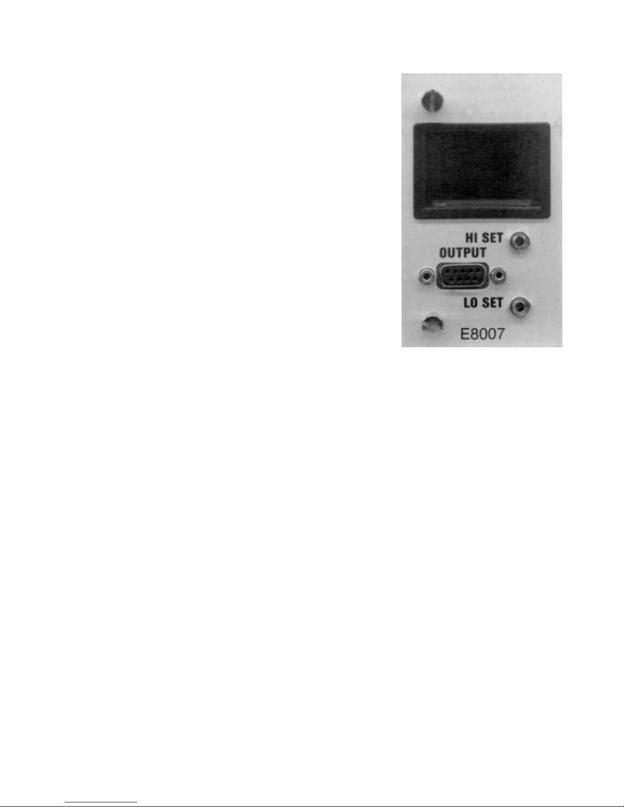
E8007 - MULTIPOINT CLASSIFYING MODULE
3-3 Functional Description
The E8007 multipoint classifying module monitors analog data
from lower bay signal conditioning modules and digitizes these
signals into a two digit, seven segment display .
Input signals are conditioned using the high set, low set pots.
This allows the user to compress or expand the specified display
information over any portion of the Trendsetter™ scale.
A front panel output connector provides an interface to programmable controllers or external logic. The connector’ s output is
custom programmed to a user specified code. The electrical
output code is current sourcing and has a resolution of 8 bits. To
utilize this function, a customer supplied external power source
is required. The power supply’s positive output is connected to
Pin 9 of the module. The power supply ground is referenced to
the load.
Controls
Adjustments
The Low and High set adjustments on the front of the E8007 module require the use of a small flat
blade screwdriver. The Low Set adjusts the magnification or spread of the display and the High Set
adjusts the zero position of the display.
Magnification is increased when the Low Set screw is turned in a clockwise direction, and is
decreased when turned in a counter-clockwise dir ection. The numerical display of the E8007 does
not reflect the change in magnification that occurs when the Low Set screw is turned. A trial and
error method will be employed until the operator obtains a feel for the amount of adjustment
required.
Set Up Procedure
1. Place either master into the gage.
2. Using the “Zero” knob on the TrendsetterTMlower bay module, set the bargraph display
to the lowest position on scale where classifying is to begin.
 Loading...