

Edmunds Accu-Touch Instruction Manual
EDMUNDS GAGES
TM
Accu-Touch
Amplifier
Instruction Manual

Accu
-
Touch
TM
Use
Step 1 – Locate the Accu-touchTM amplifier and respective gage where parts
can be best measured.
Step 2 – Connect the power cord to the rear of amplifier and then to the power
outlet. Attach a suitable air line from the air supply to the inlet of AccutouchTM filter, if applicable. Attach any LVDT cables from tooling to the rear of
amplifier noting proper location of connectors. Also attach any air lines from
the tooling to the front of the Accu-touchTM docking unit, if applicable, noting
their proper connection.
Step 3 – Turn on the power switch located at rear of the amplifier near the
power cord. Turn on the air supply pressure if applicable.
Step 4 – Have all the specific information concerning your part measurement
available i.e. max & min check sizes and max & min master calibrated sizes.
Step 5 – Setup Accu-touchTM features as described in section 1 & 2, if
necessary.
Step 6 – Calibrate Accu-touchTM using procedures listed in section 5, 6 & 7.
Step 7 – Measure parts.

Preface
The Accu-TouchTM amplifier is a “comparative” type gaging amplifier displaying
the results on a flat panel touch screen. Precision is (6m) inch with accuracy
being .5% of full scale (LVDT) and .1% full scale (AIR). Linearity will be .25%
full scale.
The Accu-TouchTM amplifier is designed to be used with Edmunds LVDT gage
probes and also two master system air tooling when used with the optional
“docking unit”. No inference to compatibility with other types or brands of
LVDT probes is implied or guaranteed.
The unit comes with a one year warranty from date of factory shipment.
Damage caused by shipping, handling, “unclean” electrical power,
contaminated compressed air supply or mis-use voids any warranty.
Tampering with internal components and loading software programs also
violates the warranty.
Basic
Amplifier (4) input p/n E7204
Amplifier (4) input w/formula generator p/n E7204A
Docking unit (1) input p/n E7110
Docking unit (2) input p/n E7120
Docking unit (3) input p/n E7130
Docking unit (4) input p/n E7140
Accessories
Coalescing Filter p/n P-NUM-F32E-04AM
Memory Stick p/n 4570642
Auto-Air shutoff (1 & 2 inputs) p/n 5917040
Auto-Air shutoff (3 & 4 inputs) p/n 5917041
USB 2-pedal Footswitch p/n 5917035

Contents
Hardware
What you need
Setup - section 1
Features - section 2
Formulas – section 3
Database setup – section 4
Setup Database 4.1
Export/Import Setups 4.2
Manual calibration – section 5
Setting pneumatic mag – section 6
Software calibration – section 7
Auto air-shutoff setup – section 8
Measuring – section 9
Data offload setup – section 10
Setup Report – section 11
Utilities – section 12
Password protection – 12.1
About - 12.2
Date/Time 12.3
Screen Colors 12.4
Backup 12.5
Notes
Appendix A – Formula Generator
Definitions
Troubleshooting
Ha
rdware
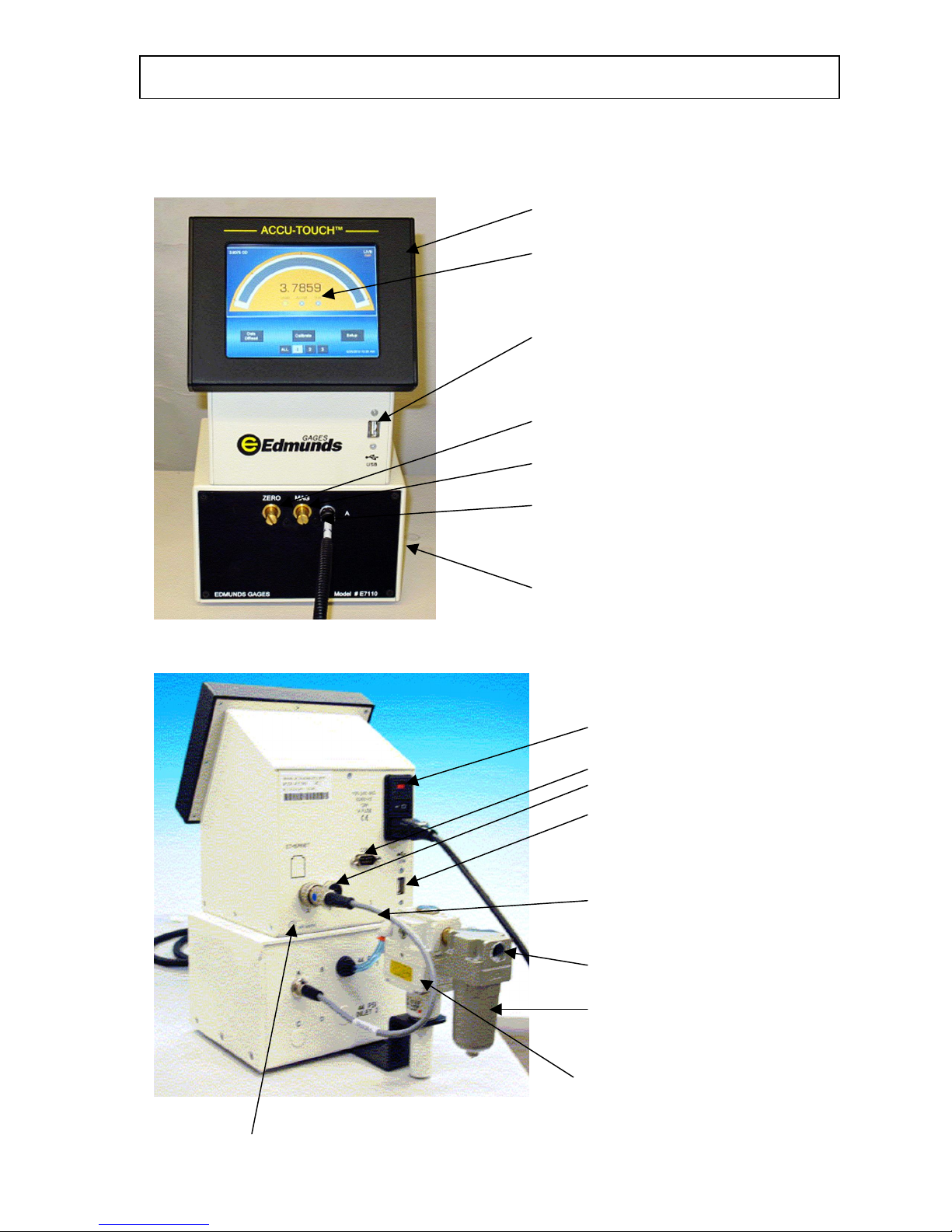
Front view
Amplifier
Touch screen
Front USB port - data offload only
Zero adjusting screw
Mag adjusting screw
Air hose, tooling connection
Docking unit air gaging – optional
Rear view
Power on/off switch
RS232C serial port
LVDT ports
rear USB port - data offload
or optional data send/TIR
reset footswitch
LVDT jumper cable,
docking unit to amplifier
Air supply inlet
Filter
Regulator
Auto-air shutoff connection - optional

What you need
5.1 - Utilities:
*1
electrical power – 110/240 VAC, 50/60 HZ.
*2
Compressed air supply – 60 PSI & 3 CFM minimum.
5.2 - Reference material: units of measure – English/Metric
upper and lower part limits
setting master *3calibrated sizes
5.3 - Measuring tooling: LVDT probes – open setup
electronic bore plug – I.D. measurement
electronic ring gage – O.D. measurement
air plug – I.D. measurement
air ring – O.D. measurement
special gage
5.4 – Setting masters: max & min or *4zero size masters -
gageblocks or other types of masters – for
electronic “open” setup gaging
ring type – for electronic or air gaging of I.D.’s
cylindrical OD type – for electronic or air gaging
of O.D.’s
Footnotes:
1.) electrical power should be “clean” and stable without large fluctuations otherwise internal
damage of electrical components can occur voiding warranty. In such cases a isolation
transformer is recommended.
2.) Clean & dry compressed air is required. Normal compressed air (shop air) can contaminate the
docking units effecting stability of the readings and voiding warranty. In such cases a coalescing
air filter is recommended to be installed on the inlet to the docking unit. The elements in this
filter require periodic checking and replacement.
3.) Certifications by a traceable calibration lab are recommended to ensure the setup and results of
calibration are as accurate as possible.
4.) A zero or nominal master can be used but not recommended by Edmunds Gages for electronic
gaging only. Two masters are required for air gaging.
Setup
–
section 1
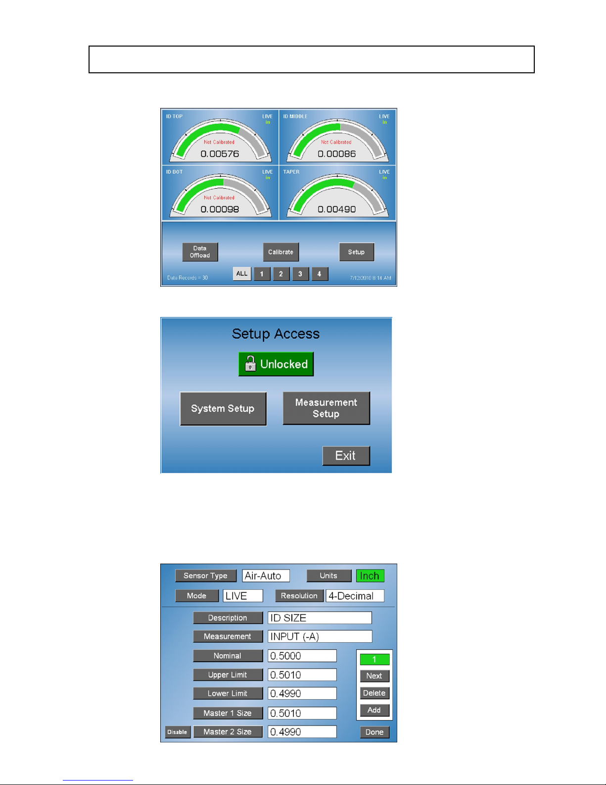
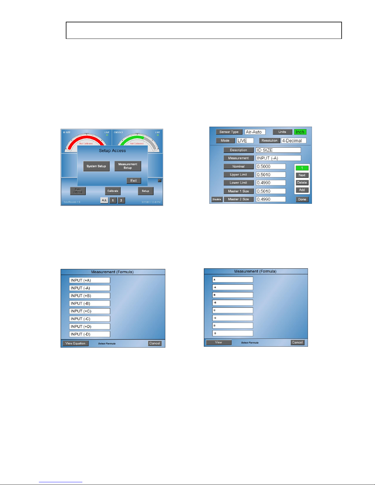
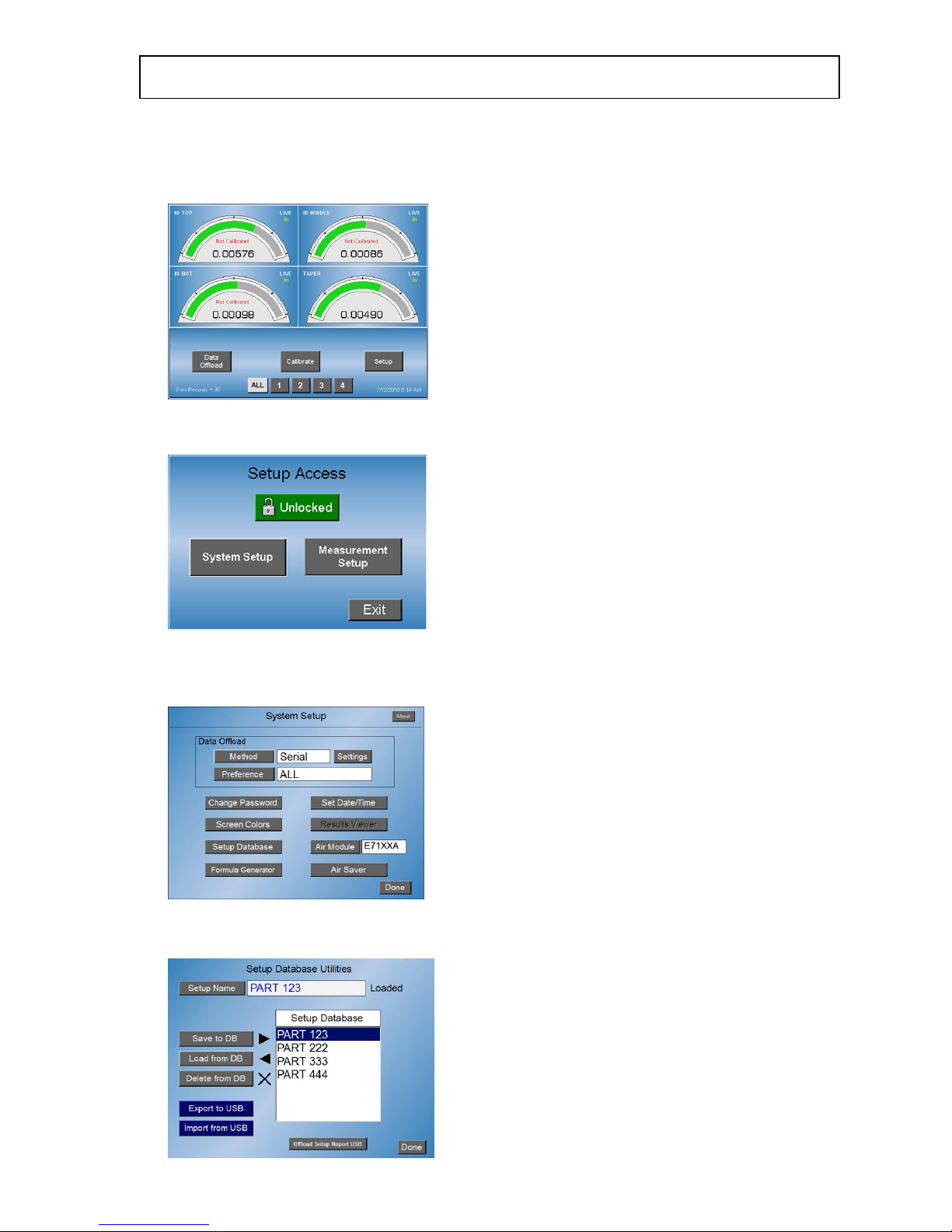
1.1 – Main screen - shown with 4 check results.
1.2 - For a new setup, touch “Setup”, “Setup Access” menu appears.
1.2.1 – Touch “Measurement Setup”, setup now appears - if unlocked or if
password protection has not been enabled.
1.2.2- The (11) selectable items related to for your use are available to be
selected or entered by touching each software key.

Features
–
section 2
2.1 - Sensor type – touch to select “electric” for electronic gaging or
air-auto for air gaging.
2.2 - Units – touch “inch” or “mm” based on application.
2.3 - Resolution – touch as many times as necessary to select
3
resolution required for application. Two to six decimal place
resolutions available.
2.4 - Mode - touch and select by touching one of four available methods
of displaying the reading. “Live”, “TIR”, “+PEAK”, “-PEAK”.
2.5 - Description – touch and enter letters, numbers or characters
using software keyboard to give a name for this measurement
feature, ten maximum. Touch “Done” when complete.
2.6 - Measurement – touch and select by touching input based on
which connection is being used for this feature being measured. Note
LVDT cable connection on rear of amplifier and 4polarity of
application.
Features
-
continued
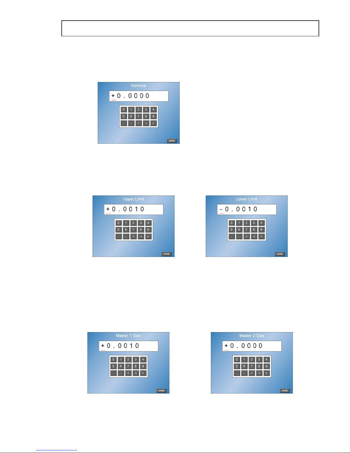
2.7 - 5Nominal – touch and enter the nominal size of your application
using the software keyboard as a “whole” number if using absolute
method or zero’s if using deviation method. Touch “Done” when
complete.
2.8 - Upper limit/Lower limit – touch and enter the upper and lower
limits of the *6part tolerance using the software keyboard. Enter
upper & lower limits as deviation (+/-) from zero or both as “whole”
numbers matching “nominal” setup, do not mix. Touch “Done” when
complete each time.
2.9 - Master 1 size/Master 2 size – touch and enter master 1 always
maximum size & master 2 always minimum size of the masters using
software keyboard. Use sizes from certifications if masters are out of
original tolerance gages were manufactured to. Enter both max &
min sizes as deviation from zero or both as “whole” numbers
matching “nominal” and “part limits”, do not mix. Touch “Done”
when complete each time. If using a single master for electronic
gaging only, use Master 1 and touch “disable” for Master 2.
2.10 - Additional checks - If more than one measurement is to be
setup, touch “add” key and repeat above setups for each
measurement. If not, touch “done” key and proceed to calibration.
Measurement (Formula)
–
section 3
3.1 – Formulas – if the standard measurement choices shown under
“Measurement” do not apply or if a special combination of inputs or formulas
are required, the formula generator option is available. The formula generator
is available on base version E7204A. Upgrade to this version is available for
purchased.
3.1.1 – Measurement – the available formulas can be viewed in the
Measurement setup. Touch the Setup software key and Setup Access menu
appears. Enter the password if required, if not touch the Measurement Setup
key to display the first check.
3.1.2 – Touch the Measurement software key to display the available
Measurement formulas. If one of the formulas shown can be used for the
application, touch to select it which will exit you to the check menu. Touch
Next for other checks and repeat the process. Touch the Done key when
finished. Use the “View Equation” so see the actual mathematical equation
assigned to the formula.
3.1.3 – If none of the available formulas is applicable, the special Formula
Generator options will be required. Touch the Cancel key to exit to the check
menu and touch the Done key to exit to main menu.
Measurement (Formula)
–
continued
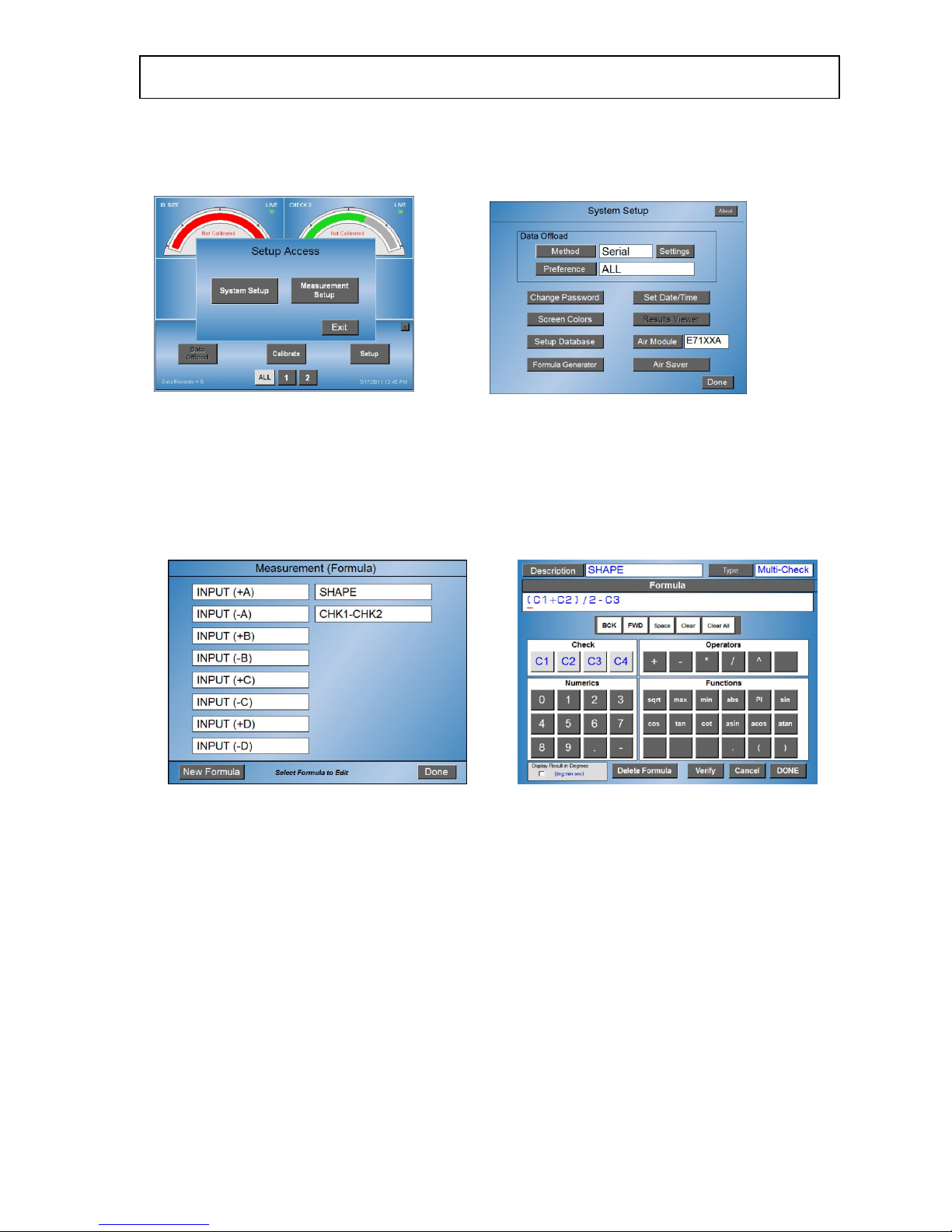
3.2.1 – Formula Generator - Touch the Setup software key and Setup Access
menu appears. Enter the password if required, if not touch the System Setup
key to display System Setup.
3.2.2 – If the optional Formula Generator (base version E7204A) has been
purchased, the Formula Generator key will be present. Touch this key to view
the existing formulas.
3.2.3 – Existing formulas – touch each to review their function should they be
applicable. Touch Done key each time to exit their function.
Measurement (Formula)
–
continued
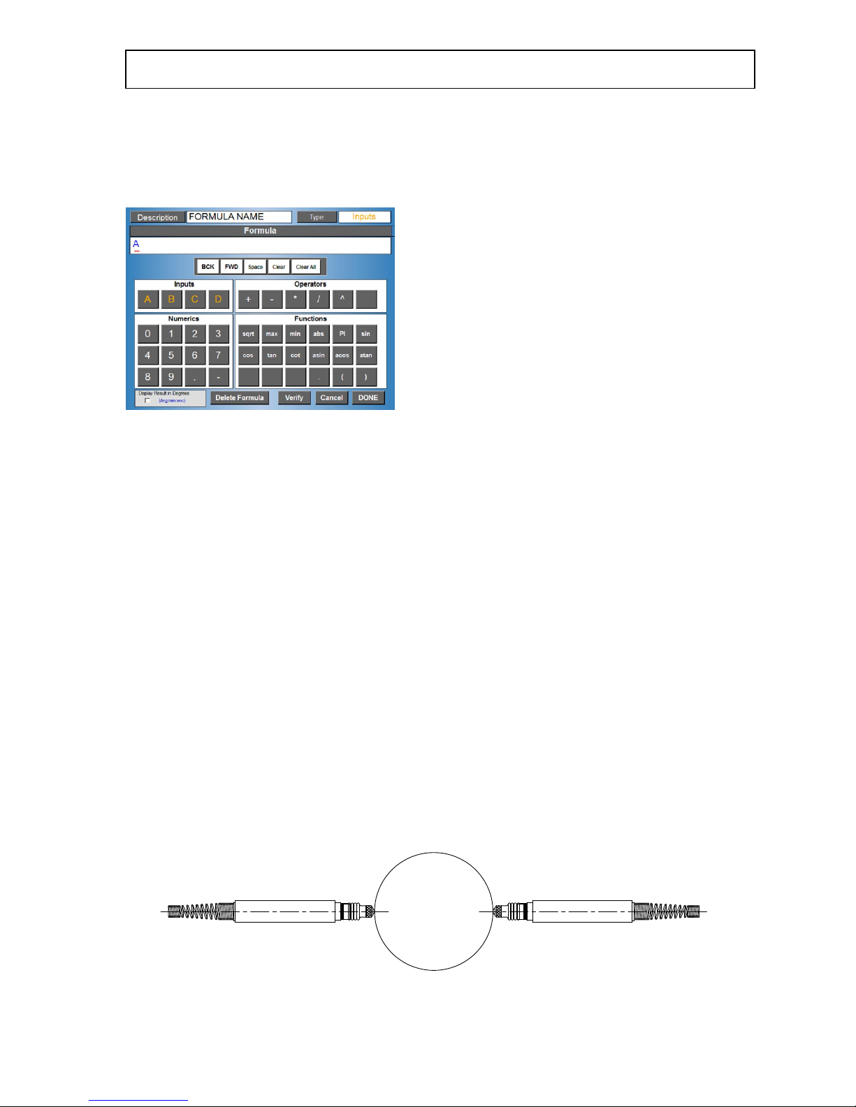
3.2.4 – If one of the existing formulas is not appropriate, touch the New
Formula software key at the lower left of the screen and formula generator
screen allowing the creation of the formula appears.
See (Appendix A – Formula Generator) for complete description.
3.2.5 - Gaging formulas – need to be understood as applied to the application
before the formula generator can be utilized. The Formula generator allows
Inputs or Checks to be algebraically combined.
For electronic gaging applications using LVDTs, the gaging formula will be
dependent upon the specific gaging application.
Gaging probes used within any system are strategically mounted to contact
the work piece at specified locations to perform measurements. The number of
probes used and their position determine the construction of the formula.
Two directly opposing LVDT probes combined to measure the OD of a shaft
would each have a polarity and mag number of (+) 1.000. The probes normal
operation defines the polarity as (+) when the tip is depressed. Thus as the
diameter grows, the probes are depressed providing positive readings
indicating a larger part diameter. The formula in this case would be “A+B”
where LVDT probes are connected to “A” and “B” inputs.
Measurement (Formula)
– continued
It may be necessary to apply a multiplier to the probes outputs depending on
the application. The multiplier is determined by the number of probes used to
perform the measurement or to correct any chordal error if they are not
equally spaced. Examples:
(2) LVDTS – directly opposed, polarity/mag = (+) 1.000
Formula = A+B
(3) LVDTS – 120 degrees equally space, polarity/mag = (+) .667
Formula = (A*.667) + (B*.667) + (C*.667) or (A+B+C)*.667
(4) LVDTS – 90 degrees equally space, polarity/mag = (+) .5
Formula = (A*.5) + (B*.5) + (C*.5) + (D*.5) or “ (A+B+C+D)*.5
For air gaging applications, the gaging formula will always be (+)1.000 outside
measurements and (-)1.000 for inside measurements. The formulas would be
“A” and “-A”
Checks can also be combine algebraically. As an example, air plug that
measures a part ID at two elevations with one labeled as the large diameter
using input A and displays as Check #1 while the other labeled as the small
diameter measured using input B and displays as Check #2. The difference
then being Taper as Check #3 can be defined as Check #1 minus Check #2.
Check #1, Large Diameter - Formula = A
Check #2, Small Diameter - Formula = B
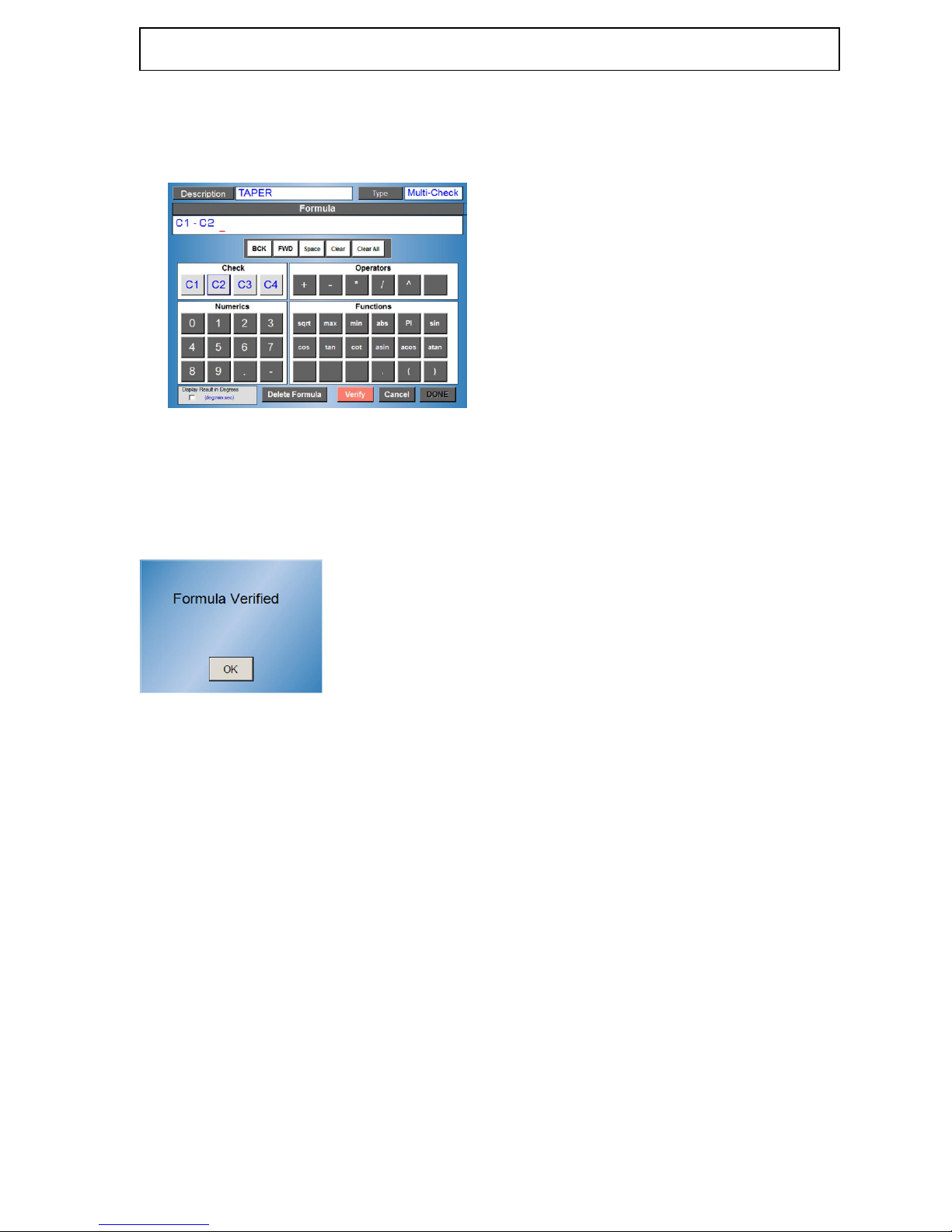
Check #3, Taper - Formula = C1 - C2
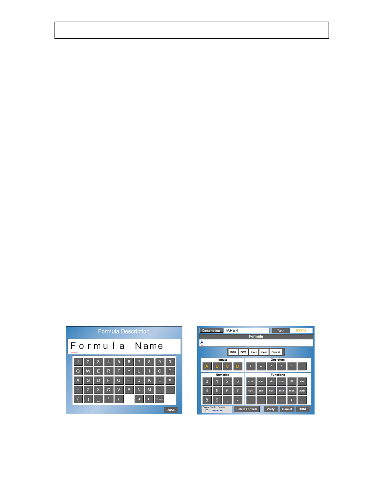
3.2.6 – Example – to create the “Taper” formula, start by touching the
Description key to enter a Formula name. A software keyboard will popup
allowing up to (14) alpha/numeric characters to be selected. Touch the Done
key when finished.
Measurement (Formula)
–
continued
3.2.6.1 – Select the “Type” key to select the “Multi-Check” format instead of the
default “Input” format. Enter the formula “C1-C2” by selecting C1 under
“Check” selection box. Select minus “-“ under the “Operators” selection box.
Select C2 under the “Check” selection box.
3.2.6.2 – Once the formula has been entered, touch the Verify key. This will
verify the formula has been entered correctly and can be used by the system.
Note that the formula must be verified before you can select “Done” and exit
the screen.
Database setup
–
section 4
4.1 - Copies of the entire setups can be stored onboard of the Accutouch
amplifier for future use. With optional version setups can be
Exported/Imported to USB drive.
4.1.1 – storing new setups - touch “Setup”, “Setup Access” menu appears.
Touch “System Setup” key, System Setup” menu now appears1 (if unlocked or
if password protection has not been enabled).
Touch the “Setup Database” key and the menu to store setups appears.
 Loading...