

Edmonds ecopower EP400, ecopower EP600 Installation Instruction
INSTALLATION INSTRUCTION
ecopower® EP400 & EP600 Hybrid Ventilator
Ta b l e 1 - Re c ommen de d Fa st e n er Q ua n t i ties
Un it Siz e
(m m)
He ad to
Vari pit ch
Vari pit ch to
Fl ash in g
Fl ash in g t o Roo f
(L oca te 4 clo se to
Vari pit ch )
400 6 6 12
600 9 9 16
Eithe r: 10 gauge 16mm tek screws wi th n eo or 5/32 bl ind rivets are
recom mended. When non sealed ri vets are used appl y silicone over
the r ivets to s eal.
PRIOR TO INSTALLATION
• Check all components are in the carton.
• It is advisable to test the ecopwer turbine, this can be done by connecting it to a power supply.
NOTE: A qualified electrician must do this.
METAL ROOF (CORRUGATED, KLIPLOCK, TRIM DECK, ETC) UNDER RIDGE INSTALLATION
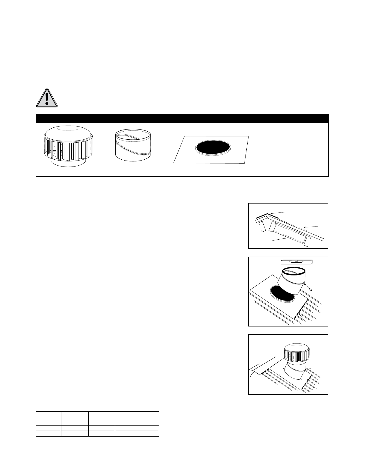
CONTENTS OF PACKAGE(S) - COMPLETE UNIT WITH VARIPITCH AND FLASHING
Turbi ne Var ipitc h Thr oat Flas hing
Also :
2 x Fixing Straps
Warranty
Installation Instructions
NOTE: The ecopower does
not include a control device.
Fi g 1
In ser t
sc rew i nto
Vari pit ch
cl ip
In fil l
Ri dge o r a pex
Be st po sit ion for
we ath erp roofi ng
Fi g 2
Tri mme rs
Step 1
Select the appropriate position on the roof as referred to in (Fig 1), ensuring the ventilator will
not be sheltered from the wind. Place the base flashing under the ridge cap.
Note: When selecting the position of the vent, the means of weather proofing needs to be
taken into account; the most efficient means is to locate the flashing under the ridge cap.
Step 2
Ensure that the flashing covers the corrugations or ribs equally, then mark a circle using the
flashing as a template. Cut hole. Once the hole has been cut, turn up the corrugations or pans.
Note: If the purlin spacing is greater than 600mm, trimmers may be required. Install the
trimmers between the purlins on either side of the opening (Fig 1). Do not cover the opening
(Fig 2).
Secure the flashing to the roof (for number of fasteners see Table 1). If trimmers are used
ensure the flashing is secured to the trimmers. It is recommended that an infill be used on the
low side of the flashing. Coat all fasteners with silicone to ensure they are weatherproof.
Step 3
When a Varipitch throat is being used, sit the Varipitch on the flashing and rotate the top and
bottom halves until the top of the Varipitch is level (horizontal); it is recommended that a level
be used (Fig 2). Fix the Varipitch to the flashing (for number of fasteners see Table 1).
Step 4
Secure the two halves of the Varipitch by inser ting self tapping screws or blind rivets into the
Varipitch clips. Run a bead of silicone around the inside of the Varipitch seam.
Note: DO NOT apply silicone to joint between flashing and Varipitch. This is a natural gutter to
release any trapped condensation.
Step 5
Fit the turbine to the Varipitch (Fig 3). Check that it is level and adjust by tilting if necessary.
Fasten the turbine to the top of the Varipitch (for number of fasteners see Table 1).
WARNING: DO NOT ATTEMPT T O INSTAL L UNIT WHEN POWER IS CONNECTED.
THE TURB INE WILL S PIN.
Ru n a
be ad of
si lic on e
ar ou nd
Vari pit ch
jo int
( ins id e)
Ri dge
or ap ex
Fi g 3
INSTALLATION INSTRUCTION
ecopower® EP400 & EP600 Hybrid Ventilator
Edmonds is a business division of CSR Building Products Limited ABN 55 008 631 356
10 Stanton Road, Seven Hills NSW 2147
Telephone 1300 858 674 www.edmonds.com.au
Global-Mark.com.au
®
Q
u
a
l
i
t
y
M
a
n
a
g
e
m
e
n
t
.
I
S
O
9
0
0
1
Elect rica l Specifi cati on
EP400 EP600
Voltage 200-277 VAC 50/60 Hz
Curre nt (A) 0.28 0.47
Power (W) 6 8 116
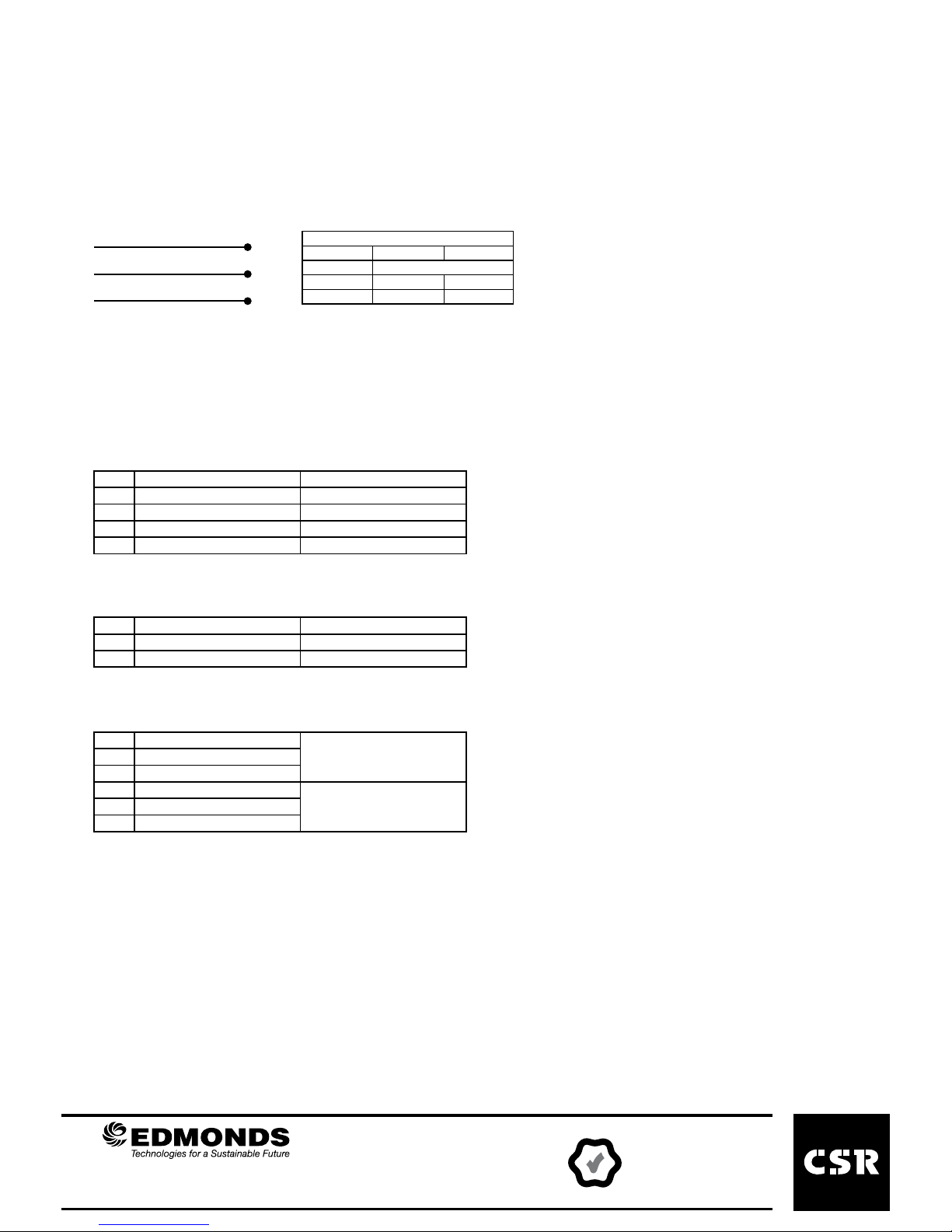
Wiri ng
THE ECOPOWER MUST BE WIRED BY A QUALIFIED ELECTRICIAN.
Bl ack Ac tiv e
Bl ue Neu tra l
Gr een /Yel low Ea rth
CONTROL DEVICES
The ecopower EP400 & EP600 can be controlled by any digital means. Edmonds stocks a range of standard controllers for
Temperature, Humidity and Internal Air Quality. The wiring connections for each are below.
240 VAC ROOM THERMOSTAT - EBERLE RTR-E 6705
Electrical Connections
3 Active Motor Connection
2 Not used for cooling
1 Active 240 VAC Mains Connection
N Not used for cooling
N Not used for cooling
ROOM HUMIDISTAT - SIEMENS QFA1001
Electrical Connections
1 Active 240 VAC Mains Connection
2 Not used for dehumidification
3 Active Motor Connection
INDOOR AIR QUALIT Y CONTROLLER - SIEMENS QPA84
Electrical Connections
Y1 Active
Motor ConnectionN Neutral
╧ Earth
╧ Earth
240 VAC Mains ConnectionN Neutral
L Active
Publish date: 08/11
Doc ref: I-104-B
 Loading...