

EDM Solution Ultima 844, Solution Ultima 880, Solution Ultima 862 Installation Manual

Solution Ultima 844/862/880
Installation Manual
ISSUE 1.62


This page has been included for you to cut out and insert into the spine
MA48XI
Solution
of the folder
Ultima
844
/862
/880
Installation
Manual
ISSUE 1.62
(61-2) 9672 1233


Solution Ultima 844/862/880
Installation Manual
Copyright 2001 by Electr onic s Design and Ma nufacturing Pty Limited,
SYDNEY, AUSTRALIA
Document Part Number MA48XI
DOCUMENT ISSUE 1.62
Printed 29 October 2001
This documentation is provided to suit
Alarm Link required = 2.74 or higher
Control Panel Software Version 1.00 - 1.09 = S844_V10
Copyright Notice
All rights reserved. No part of this publication may be reproduced, sent or stored in a retrieval system in any form or by any
means, electronic, mechanical, photocopying, recording, or other wise, without the prior written permission o f Electronics
Design and Manufacturing Pty Limited.
Trademarks
Throughout this document trademark names may have been used. Rather than put a trademark symbol in every occurrence
of a trademark name, we state that we are using the names only in an editorial fas hion and to the benefit of the trademark
owner with no intention of infringement of the trademark.
Solution Ultima 844/862/880 Control Panel
(CC484/CC486/CC488)
Firmware Revision 1.00 – 1.09
Hardware Revision A - J
= S862_V10
= S880_V10
Notice of Liability
While every precaution has been taken in the preparation of this document, neither Electronics Design and Manufacturing
Pty Limited nor any of its official representatives shall have any liability to any person or entity with respect to any
liability, loss or damage caused or alleged to be caused directly or indirectly by the information contained in this book.
Electronics Design and Manufacturing Pty Limited reserves the right to make c hanges to features and specificatio ns at an y
time without prior notification in the interest of ongoing product development and improvement.


Table Of Contents
Introduction _____________________________________________________________________ 17
Introduction__________________________________________________________________________ 18
Solution Ultima 844 Features____________________________________________________________ 19
Solution Ultima 862 Features____________________________________________________________ 20
Solution Ultima 880 Features____________________________________________________________ 21
Quick Start___________________________________________________________________________ 22
Solution Ultima 844 Zone Defaults________________________________________________________________ 24
Solution Ultima 862 Zone Defaults________________________________________________________________ 24
Solution Ultima 880 Zone Defaults________________________________________________________________ 24
Zone Types __________________________________________________________________________________ 25
Codepad Indicators _______________________________________________________________ 27
CP5 Eight Zone LED Codepad __________________________________________________________ 28
Zone Indicators _______________________________________________________________________________ 28
AWAY Indicator______________________________________________________________________________ 28
STAY Indicator_______________________________________________________________________________ 29
MAINS Indicator _____________________________________________________________________________ 29
FAULT Indicator _____________________________________________________________________________ 29
Audible Indicators_____________________________________________________________________________ 30
CP5 Eight Zone LCD Codepad __________________________________________________________ 31
Zone Indicators _______________________________________________________________________________ 31
AWAY Indicator______________________________________________________________________________ 31
STAY Indicator_______________________________________________________________________________ 32
System Disarmed _____________________________________________________________________________ 32
MAINS Indicator _____________________________________________________________________________ 32
FAULT Indicator _____________________________________________________________________________ 33
Programming Mode ___________________________________________________________________________ 33
Off Indicator/Zone Sealed_______________________________________________________________________ 33
On Indicator/Zone In Alarm _____________________________________________________________________ 33
Audible Indicators_____________________________________________________________________________ 34
CP5 Master Partitioned LED Codepad____________________________________________________ 35
Zone Indicators _______________________________________________________________________________ 35
Area On/Off Indicators _________________________________________________________________________ 35
Area Display Indicators_________________________________________________________________________ 36
Status Indicators ______________________________________________________________________________ 36
PARTIAL Indicator _________________________________________________________________________ 36
AUX Indicator______________________________________________________________________________ 36
MAINS Indicator ___________________________________________________________________________ 37
FAULT Indicator ___________________________________________________________________________ 37
Audible Indicators___________________________________________________________________________ 37
System Operations ________________________________________________________________ 39
System Operations_____________________________________________________________________ 40
Arming The System In AWAY Mode _____________________________________________________________ 40
Forced Arming _____________________________________________________________________________ 40
Disarming The System From AWAY Mode_________________________________________________________ 41
Arming The System In STAY Mode 1 _____________________________________________________________ 42
Entry Guard Timer For STAY Mode ____________________________________________________________ 42
Forced Arming _____________________________________________________________________________ 43
Disarming The System From STAY Mode 1 ________________________________________________________ 44
Arming The System In STAY Mode 2 _____________________________________________________________ 45
Entry Guard Timer For STAY Mode ____________________________________________________________ 45
Forced Arming _____________________________________________________________________________ 45
Disarming The System From STAY Mode 2 ________________________________________________________ 46

Codepad Duress Alarm_________________________________________________________________________ 47
Codepad Panic Alarm__________________________________________________________________________ 47
Codepad Fire Alarm ___________________________________________________________________________ 47
Codepad Medical Alarm________________________________________________________________________ 47
Isolating Zones ________________________________________________________________________ 48
Standard Isolating ___________________________________________________________________________ 49
Code To Isolate_____________________________________________________________________________ 50
Fault Analysis Mode____________________________________________________________________ 51
Fault Descriptions _____________________________________________________________________ 53
System Fault _________________________________________________________________________________ 53
Low Battery _______________________________________________________________________________ 53
Date and Time______________________________________________________________________________ 53
RF Receiver Fail ____________________________________________________________________________ 53
Horn Speaker ______________________________________________________________________________ 53
Telephone Line Fail _________________________________________________________________________ 53
E2 Fault___________________________________________________________________________________ 53
Fuse Fail __________________________________________________________________________________ 53
RF Low Battery ______________________________________________________________________________ 53
Tamper Fail__________________________________________________________________________________ 54
Sensor Watch Fault____________________________________________________________________________ 54
RF Sensor Watch Fault_________________________________________________________________________ 54
Communication Fail ___________________________________________________________________________ 54
AC Mains Failure ___________________________________________________________________________ 54
Remote Radio Transmitter Operations ________________________________________________ 55
Remote Radio Transmitter Operations ____________________________________________________ 56
Indications Upon Remote Radio Transmitter Operations_______________________________________________ 57
Remote Radio User Code Priority Levels___________________________________________________________ 57
Changing Or Deleting Remote Radio User Codes ____________________________________________________ 58
System Functions _________________________________________________________________ 61
System Functions ______________________________________________________________________ 62
Installer Code Functions ________________________________________________________________________ 62
Adding Or Deleting RF Wireless Devices ________________________________________________________ 63
Set The Number Of Days Until The First Test Report _______________________________________________ 65
Changing Domestic Phone Numbers ____________________________________________________________ 66
Change Telco Arm/Disarm Sequence ____________________________________________________________ 68
Setting STAY Mode 2 Zones __________________________________________________________________ 71
Satellite Siren Service Mode___________________________________________________________________ 72
Turning Telephone Monitor Mode On/Off________________________________________________________ 73
Walk Test Mode ____________________________________________________________________________ 74
Event Memory Recall Mode___________________________________________________________________ 75
Master Code Functions _________________________________________________________________ 76
Arm or Disarm Both Areas At The Same Time ____________________________________________________ 76
Changing and Deleting User Codes _____________________________________________________________ 77
Changing and Deleting Remote Radio User Codes _________________________________________________ 79
Changing Domestic Phone Numbers ____________________________________________________________ 81
Change Telco Arm/Disarm Sequence ____________________________________________________________ 83
Setting STAY Mode 2 Zones __________________________________________________________________ 86
Turning Outputs On/Off ______________________________________________________________________ 87
Setting The Date and Time ____________________________________________________________________ 89
Walk Test Mode ____________________________________________________________________________ 90
Event Memory Recall Mode___________________________________________________________________ 91
User Code Functions ___________________________________________________________________ 92
Arm or Disarm Both Areas At The Same Time ____________________________________________________ 92
Hold Down Functions___________________________________________________________________ 93
Arm The System In AWAY Mode______________________________________________________________ 93
Arm The System In STAY Mode 1 _____________________________________________________________ 93
Arm The System In STAY Mode 2 _____________________________________________________________ 94
Horn Speaker Test __________________________________________________________________________ 94
Bell Test __________________________________________________________________________________ 94

Strobe Test ________________________________________________________________________________ 94
Turning Day Alarm On and Off ________________________________________________________________ 95
Fault Analysis Mode _________________________________________________________________________ 95
Initiate A Modem Call _______________________________________________________________________ 96
Reset Latching Outputs _______________________________________________________________________ 96
Codepad Buzzer Tone Change _________________________________________________________________ 97
Send Test Report____________________________________________________________________________ 97
Remote System___________________________________________________________________ 99
Operations Via Telephone__________________________________________________________ 99
Remote Arming Via The Telephone _____________________________________________________ 100
Programming___________________________________________________________________ 101
Programming________________________________________________________________________
Programming With The Remote Codepad ________________________________________________
102
103
Programming With The Hand Held Programmer__________________________________________ 105
Programming With The Programming Key_______________________________________________ 106
Programming Option Bits _____________________________________________________________
Installer’s Programming Commands ____________________________________________________
Command 958 - Enable/Disable Zone Status Mode __________________________________________________ 108
Command 959 - Test Programming Key __________________________________________________________
Command 960 - Exit Installer's Programming Mode _________________________________________________ 110
Command 961- Reset Control Panel Back To Factory Default Settings___________________________________ 110
Command 962 - Copy Control Panel Memory To Programming Key ____________________________________ 111
Command 963 - Copy From Programming Key To Control Panel_______________________________________ 112
Command 964 - Erase Programming Key _________________________________________________________
Command 965 - Set Up Domestic Dialling Format __________________________________________________
Command 966 - Enable/Disable Automatic Stepping Of Locations______________________________________
Command 999 - Display Panel Type Or Software Version Number _____________________________________
Disable Factory Default _______________________________________________________________________
Defaulting The Control Panel ___________________________________________________________________ 119
107
107
109
113
114
115
117
118
Alarm Link Operations ___________________________________________________________ 121
Alarm Link Software _________________________________________________________________
Remote Connect _____________________________________________________________________________
Remote Connect With Customer Control ________________________________________________________ 122
Remote Connect Without Call Back Verification __________________________________________________
Remote Connect With Call Back Verification ____________________________________________________
Direct Connect ____________________________________________________________________________
Alarm Link Options __________________________________________________________________________
Enable Upload/Download Via Alarm Link_______________________________________________________
Enable Alarm Link Call Back _________________________________________________________________
Terminate Alarm Link Connection On Alarm ____________________________________________________ 124
Use External Modem Module (CC811) For Alarm Link Operations ___________________________________
122
122
123
123
123
124
124
124
124
Domestic Dialling _______________________________________________________________
125
Domestic Dialling Format______________________________________________________________ 126
Domestic Dialling Function ____________________________________________________________________ 126
Acknowledge Domestic Dialling ______________________________________________________________ 126
Setting Up and Programming Domestic Reporting___________________________________________________ 127
Disable Domestic Dialling ___________________________________________________________________ 128
Dialler Reporting Formats ________________________________________________________ 129
Transmission Formats ________________________________________________________________ 130
Contact ID Format ___________________________________________________________________________ 130
Point ID Codes ______________________________________________________________________________ 131
4+2 Reporting Format_________________________________________________________________________ 133
Basic Pager Reporting Format __________________________________________________________________ 134

Basic Pager Display Information ________________________________________________________ 135
Subscriber ID Number ________________________________________________________________________ 135
Zone Status _________________________________________________________________________________ 135
System Status _______________________________________________________________________________ 135
Dialler Information ______________________________________________________________ 137
Dialler Information ___________________________________________________________________ 138
Primary Telephone Number For Receiver 1________________________________________________________ 139
Secondary Telephone Number For Receiver 1______________________________________________________ 139
Handshake Tone For Receiver 1_________________________________________________________________ 140
Transmission Format For Receiver 1 _____________________________________________________________ 141
Subscriber ID Number For Receiver 1 ____________________________________________________________ 141
Primary Telephone Number For Receiver 2________________________________________________________
Secondary Telephone Number For Receiver 2______________________________________________________ 142
Handshake Tone For Receiver 2_________________________________________________________________ 143
Transmission Format For Receiver 2 _____________________________________________________________ 144
Subscriber ID Number For Receiver 2 ____________________________________________________________ 144
Dialling Format______________________________________________________________________________ 145
Reserved ___________________________________________________________________________________ 145
Telco Arming Sequence _______________________________________________________________________ 146
Telco Arming – Call Forward Immediate On_____________________________________________________ 146
Telco Arming – Call Forward No Answer On ____________________________________________________ 146
Telco Disarming Sequence _____________________________________________________________________ 147
Telco Arming – Call Forward Immediate Off ____________________________________________________ 147
Telco Arming – Call Forward No Answer Off ____________________________________________________ 147
Call Back Telephone Number___________________________________________________________________ 147
Ring Count _________________________________________________________________________________ 148
Answering Machine Bypass ____________________________________________________________________ 148
Telephone Line Fault Options __________________________________________________________________ 149
Operate The FAULT Indicator When Telephone Line Fails _________________________________________ 149
Sound Speaker, Bell and Strobe When The System Is Armed ________________________________________ 149
Sound Speaker, Bell and Strobe When The System Is Disarmed______________________________________ 149
Reserved _________________________________________________________________________________ 149
Ring Burst Time _____________________________________________________________________________ 150
142
Dialler Options __________________________________________________________________ 151
Programming Option Bits ______________________________________________________________ 152
Dialler Options 1 ____________________________________________________________________________ 153
Dialler Reporting Functions Allowed___________________________________________________________ 153
Disabled = Disable All Dialler Reporting Functions _______________________________________________ 153
Remote Arming Via The Telephone Allowed ____________________________________________________ 153
Answering Machine Bypass Only When Armed __________________________________________________ 153
Use Bell 103 For FSK Format (Disabled = CCITT V21 Format) _____________________________________ 153
Dialler Options 2 ____________________________________________________________________________ 154
Open/Close Reports Only If Previous Alarm _____________________________________________________ 154
Open/Close Reports For STAY Mode 1 and STAY Mode 2 _________________________________________ 154
Delay Siren Until Transmission Complete _______________________________________________________ 154
Extend Time To Wait For Handshake From 30 - 55 Seconds ________________________________________ 154
Dialler Options 3 ____________________________________________________________________________ 155
Set DTMF Dialling Pulses To 1 Digit/Second ____________________________________________________ 155
Lockout Telephone Line Fail Alarm____________________________________________________________ 155
Change Decadic Dialling To 60/40_____________________________________________________________ 155
External Modem Module (CC811) Required For FSK _____________________________________________ 155
Alarm Link Options __________________________________________________________________________ 156
Upload/Download Allowed __________________________________________________________________ 156
Call Back Phone Number Required For Upload/Download __________________________________________ 156
Exit Upload/Download Connection On Alarm____________________________________________________ 156
External Modem Module (CC811) Required For Upload/Download___________________________________ 156

User Codes _____________________________________________________________________ 157
Access Codes ________________________________________________________________________ 158
Installer Code _______________________________________________________________________________ 158
User Codes _________________________________________________________________________________ 159
Solution Ultima 844/862 User Codes _____________________________________________________________ 160
Solution Ultima 880 User Codes_________________________________________________________________ 160
User Code Priority ___________________________________________________________________________
Arm and Disarm ___________________________________________________________________________ 161
Arm Only ________________________________________________________________________________ 161
Arm and Disarm + Open/Close Reports _________________________________________________________ 161
Arm Only + Closing Reports _________________________________________________________________
Arm and Disarm + Code To Isolate ____________________________________________________________ 162
Arm and Disarm + Code To Isolate + Open/Close Reports __________________________________________ 162
Arm and Disarm + Master Code Functions_______________________________________________________ 162
Arm and Disarm + Master Code Functions + Open/Close Reports ____________________________________
Arm and Disarm + Master Code Functions + Code To Isolate________________________________________
Arm and Disarm + Master Code Functions + Code To Isolate + Open/Close Reports______________________ 162
161
161
162
162
Zone Information _______________________________________________________________
Day Alarm Zones ____________________________________________________________________________
Day Alarm Resetting________________________________________________________________________
Day Alarm Latching ________________________________________________________________________ 164
Day Alarm Operation _________________________________________________________________________
EOL Resistor Value __________________________________________________________________________
Connections Of Split EOL Resistors Using N/C Contacts _____________________________________________
Connections Of Split EOL Resistors With Tamper Circuit ____________________________________________
Connections Of Split EOL Resistors Using N/O Contacts _____________________________________________ 168
Zone Programming ___________________________________________________________________
Zone Operating Information ____________________________________________________________________ 169
Zone Options________________________________________________________________________________
Zone Reporting Information ____________________________________________________________________ 169
Solution Ultima 844 Zones Defaults______________________________________________________________
Solution Ultima 862 Zones Defaults______________________________________________________________
Solution Ultima 880 Zones Defaults______________________________________________________________
Zone Types _________________________________________________________________________________ 171
Instant Zone_______________________________________________________________________________ 171
Handover Zone ____________________________________________________________________________
Delay-1 Zone______________________________________________________________________________ 171
Delay-2 Zone______________________________________________________________________________ 171
Reserved _________________________________________________________________________________
Reserved _________________________________________________________________________________
24 Hour Medical ___________________________________________________________________________ 172
24 Hour Panic _____________________________________________________________________________ 172
24 Hour Hold-Up __________________________________________________________________________
24 Hour Tamper ___________________________________________________________________________
Reserved _________________________________________________________________________________
Keyswitch Zone ___________________________________________________________________________
24 Hour Burglary Zone ______________________________________________________________________
24 Hour Fire Zone__________________________________________________________________________
Chime Zone_______________________________________________________________________________ 173
Zone Not Used ____________________________________________________________________________ 173
Zone Pulse Count ____________________________________________________________________________ 173
Zone Pulse Count Handover __________________________________________________________________ 173
Zone Pulse Count Time________________________________________________________________________ 174
Zone Options 1 ______________________________________________________________________________
Lockout Siren & Lockout Dialler ______________________________________________________________ 175
Delay Alarm Reporting ______________________________________________________________________
Silent Alarm ______________________________________________________________________________ 176
Sensor Watch _____________________________________________________________________________ 176
Keyswitch Zone Options_______________________________________________________________________ 177
Latching Arm and Disarm In AWAY Mode______________________________________________________ 177
Latching Arm In AWAY Mode _______________________________________________________________ 177
Latching Disarm From AWAY Mode, STAY Mode 1 Or STAY Mode 2 _______________________________ 177
Latching Arm and Disarm In STAY Mode 1 _____________________________________________________
163
164
164
165
166
167
167
169
169
170
170
170
171
171
172
172
172
172
172
172
172
175
175
177

Latching Arm In STAY Mode 1_______________________________________________________________ 177
Latching Disarm From STAY Mode 1 Or STAY Mode 2 ___________________________________________ 177
Momentary Arm and Disarm In AWAY Mode ___________________________________________________ 178
Momentary Arm In AWAY Mode _____________________________________________________________ 178
Momentary Disarm From AWAY Mode, STAY Mode 1 Or STAY Mode 2 ____________________________ 178
Momentary Arm and Disarm In STAY Mode 1 ___________________________________________________ 178
Momentary Arm In STAY Mode 1 ____________________________________________________________ 178
Momentary Disarm From STAY Mode 1 Or STAY Mode 2_________________________________________ 178
Zone Options 2 ______________________________________________________________________________ 179
Isolate In STAY Mode 1_____________________________________________________________________ 179
Zone Isolation Allowed _____________________________________________________________________ 179
Forced Arming Allowed _____________________________________________________________________ 179
Zone Restore Report________________________________________________________________________ 179
Zone Reporting Information ____________________________________________________________________ 180
Zone Report Code__________________________________________________________________________ 180
Zone Dialler Options _______________________________________________________________________ 180
Swinger Shutdown Count For Siren ______________________________________________________________ 181
Swinger Shutdown Count For Dialler ____________________________________________________________ 182
System Reporting Information _____________________________________________________ 183
Reporting Information_________________________________________________________________ 184
Zone Status – Zone Tamper Report ______________________________________________________________ 184
Zone Status – Walk Test Report_________________________________________________________________ 184
Zone Status – Bypass Reports __________________________________________________________________ 185
Zone Status – Trouble Reports __________________________________________________________________ 185
Zone Status – Sensor Watch Reports _____________________________________________________________ 186
Zone Status – Alarm Restore Code_______________________________________________________________ 186
Zone Status Reporting Options__________________________________________________________________ 186
RF Supervision Time _________________________________________________________________________ 187
RF Low Battery Report _______________________________________________________________________ 187
RF Receiver Trouble Report____________________________________________________________________ 188
RF Receiver Trouble Restore Report _____________________________________________________________ 188
RF Dialler Options ___________________________________________________________________________ 188
Open/Close Reports __________________________________________________________________________ 189
Open/Close Reporting Options__________________________________________________________________ 189
Codepad Duress Report _______________________________________________________________________ 190
Codepad Panic Report ________________________________________________________________________ 190
Codepad Fire Report__________________________________________________________________________ 191
Codepad Medical Report ______________________________________________________________________ 191
Codepad Reporting Options ____________________________________________________________________ 192
System Status – Fuse Fail Report ________________________________________________________________ 192
System Status – Fuse Fail Restore Report _________________________________________________________ 192
System Status – AC Fail Report _________________________________________________________________ 193
System Status – AC Fail Restore Report __________________________________________________________ 193
System Status - Low Battery Report______________________________________________________________ 194
System Status - Low Battery Restore Report _______________________________________________________ 194
System Status - Access Denied __________________________________________________________________ 195
Code Retries ______________________________________________________________________________ 195
System Status Reporting Options ________________________________________________________________ 196
Test Reporting Time__________________________________________________________________________ 197
Test Reporting Dialler Options__________________________________________________________________ 197
Programmable Outputs ___________________________________________________________ 199
Outputs _____________________________________________________________________________ 200
Output Defaults______________________________________________________________________________ 200
Default For Strobe ___________________________________________________________________________ 200
Default For Entry/Exit ________________________________________________________________________ 200
Redirecting Outputs To The Codepad Buzzer ______________________________________________________ 201
Output Event Types __________________________________________________________________________ 202
Output Polarity ______________________________________________________________________________ 211
Output Not Used___________________________________________________________________________ 211
Normally Open, Going Low __________________________________________________________________ 211
Normally Open, Pulsing Low _________________________________________________________________ 211
Normally Open, One Shot Low _______________________________________________________________ 211
Normally Open, One Shot Low With Retrigger ___________________________________________________ 211

Normally Open, One Shot Low With Reset ______________________________________________________ 211
Normally Open, One Shot Low With Alarm______________________________________________________ 212
Normally Open, Latching Low ________________________________________________________________ 212
Normally Low, Going Open __________________________________________________________________ 212
Normally Low, Pulsing Open _________________________________________________________________ 212
Normally Low, One Shot Open________________________________________________________________ 212
Normally Low, One Shot Open With Retrigger ___________________________________________________ 212
Normally Low, One Shot Open With Reset ______________________________________________________
Normally Low, One Shot Open With Alarm______________________________________________________ 212
Normally Low, Latching Open ________________________________________________________________ 212
Timing Of Outputs ___________________________________________________________________________
Pulsing Polarities_____________________________________________________________________________ 213
One Shot Polarities ___________________________________________________________________________ 214
212
213
System Event Timers _____________________________________________________________ 215
System Event Timers _________________________________________________________________
Programming Entry/Exit Timers_________________________________________________________________
Entry Timer 1 _______________________________________________________________________________
Entry Timer 2 _______________________________________________________________________________
Exit Time __________________________________________________________________________________
Entry Guard Timer For STAY Mode _____________________________________________________________
Delay Alarm Reporting Time ___________________________________________________________________ 217
Sensor Watch Time___________________________________________________________________________
Codepad Lockout Time________________________________________________________________________ 218
Siren Run Time ______________________________________________________________________________
Siren Sound Rate_____________________________________________________________________________ 219
Auto Arming Pre-Alert Timer___________________________________________________________________
Auto Arming Time ___________________________________________________________________________
Auto Disarming Time _________________________________________________________________________ 221
Kiss-Off Wait Time __________________________________________________________________________
Speaker Beep Volume_________________________________________________________________________
System Time ________________________________________________________________________________ 222
System Date ________________________________________________________________________________ 223
Setting The Date and Time ___________________________________________________________________ 223
System and Consumer Options _____________________________________________________
Programming Option Bits _____________________________________________________________
System Options 1 ____________________________________________________________________________ 227
EDM Smart Lockout Allowed ________________________________________________________________
Horn Speaker Monitor_______________________________________________________________________ 227
Strobe Indications For Radio Arm/Disarm _______________________________________________________ 227
Assign Button 4 On Transmitter To Arm STAY Mode 1 ____________________________________________
System Options 2 ____________________________________________________________________________ 228
Codepad Panic To Be Silent __________________________________________________________________ 228
Codepad Fire To Be Silent ___________________________________________________________________
Codepad Medical To Be Silent ________________________________________________________________ 228
Access Denied To Be Silent __________________________________________________________________
System Options 3 ____________________________________________________________________________ 229
AC Fail In 1 Hour (Disabled = After 2 Minutes) __________________________________________________
Ignore AC Fail ____________________________________________________________________________
Zone Pulse Count Handover Allowed___________________________________________________________ 229
Handover Delay To Be Sequential _____________________________________________________________ 229
System Options 4 ____________________________________________________________________________ 230
Panel To Power Up Disarmed (If Power Reset) ___________________________________________________ 230
Arm/Disarm Tracking On Power Up ___________________________________________________________
Internal Crystal To Keep Time ________________________________________________________________ 230
Keyswitch Interface, Night Arm Station Or RE005 Installed _________________________________________
Consumer Options 1 __________________________________________________________________________ 231
Test Reports Only When Armed_______________________________________________________________
Test Report After Siren Reset ________________________________________________________________ 231
Auto Arm In STAY Mode 1 __________________________________________________________________ 231
STAY Indicator To Display Day Alarm Status ___________________________________________________
216
216
216
216
217
217
218
219
220
220
221
221
225
226
227
227
228
228
229
229
230
230
231
231

Consumer Options 2 __________________________________________________________________________ 232
Codepad Display Extinguish After 60 Seconds ___________________________________________________ 232
Single Button Arming Allowed (AWAY Mode, STAY Mode 1 & 2) __________________________________ 232
Single Button Disarming Allowed (STAY Mode 1 & 2) ____________________________________________ 232
Alarm Memory Reset On Disarm______________________________________________________________ 232
Consumer Options 3 __________________________________________________________________________ 233
Codepad Fault Alarm Beeps Allowed __________________________________________________________ 233
Use Digit 3 For Codepad Duress Instead Of Digit 9 _______________________________________________ 233
Alarms Activate Siren & Strobe In STAY Mode 1 & 2 _____________________________________________ 233
Zone Tamper Alarms To Be Silent_____________________________________________________________ 233
Radio Input Options __________________________________________________________________________ 234
DS304 MHz Receiver (RF3212) ______________________________________________________________ 234
Latching Keyswitch Input____________________________________________________________________ 234
Momentary Keyswitch Input _________________________________________________________________ 234
Partitioning_____________________________________________________________________ 235
CP5 Master Partitioned LED Codepad ___________________________________________________ 236
Zone Indicators ______________________________________________________________________________ 236
Area On/Off Indicators ________________________________________________________________________ 237
Area Display Indicators _______________________________________________________________________ 237
Status Indicators _____________________________________________________________________________ 237
PARTIAL Indicator ________________________________________________________________________ 237
AUX Indicator ____________________________________________________________________________ 238
MAINS Indicator __________________________________________________________________________ 238
FAULT Indicator __________________________________________________________________________ 238
Audible Indicators _________________________________________________________________________ 239
Operating Codepads In Partitioning _____________________________________________________ 240
Operating From A CP5 Area Addressable LED Codepad ___________________________________________ 240
Operating From A CP5 Master Partitioned Codepad _______________________________________________ 240
Programming ________________________________________________________________________
Partitioning Options 1_________________________________________________________________________ 241
First To Open/Last To Close Reporting _________________________________________________________ 241
Area 1Codepad Connected To Data Terminal ____________________________________________________ 241
Reset Sirens From Any Area Allowed __________________________________________________________ 242
Master Codepad To Display AUX Indicator When On-Line _________________________________________ 242
Partitioning Options 2_________________________________________________________________________ 242
Lock Area 1 To Receiver 1 and Lock Area 2 To Receiver 2 _________________________________________ 242
User Code Allowed To Arm/Disarm Both Areas At Same Time ______________________________________ 242
Reserved _________________________________________________________________________________ 242
Reserved _________________________________________________________________________________ 242
Zone Allocations ______________________________________________________________________
Zone Allocations For Area 1 ___________________________________________________________________ 243
Zone Allocations For Area 2 ___________________________________________________________________ 243
User Code Allocations _________________________________________________________________
Setting Up and Programming Codepads For Partitioning____________________________________
Setting Up The Master Partitioned Codepad As The Main Codepad. __________________________________ 246
Setting Up An Area 1 Codepad As The Main Codepad _____________________________________________ 246
Setting Up An Area 1 Codepad _______________________________________________________________ 246
Setting Up An Area 2 Codepad _______________________________________________________________ 246
241
243
245
246
Codepad Connections For Partitioning - Examples _________________________________________ 247
RF Information _________________________________________________________________ 249
RF Option Bit _______________________________________________________________________________ 250
Sound Siren On RF Receiver Fail______________________________________________________________ 250
Sound Siren On RF Receiver Tamper / Jamming__________________________________________________ 250
Unseal Zone That Fails Supervision____________________________________________________________ 250
Enable RF Jamming Monitoring_______________________________________________________________ 250
RF Device Mapping (Devices 1 – 8) _____________________________________________________________ 250
RF Device Mapping (Devices 9 – 16) ____________________________________________________________ 250
RF Device Signal Strength (Devices 1 – 8 Read Only) _______________________________________________ 251
RF Device Signal Strength (Devices 9 – 16 Read Only) ______________________________________________ 251

Optional Equipment _____________________________________________________________ 253
Optional Equipment __________________________________________________________________ 254
Terminals and Descriptions _______________________________________________________ 257
Terminal Definitions and Descriptions ___________________________________________________ 258
Glossary Of Terms ___________________________________________________________________
Solution Ultima 844/862/880 Wiring Diagram _____________________________________________ 262
Solution Ultima 844/862/880 Component Overlay__________________________________________
RF3212 Radio Receiver Wiring Diagram _________________________________________________ 264
Telecom Connection Diagrams _________________________________________________________ 265
Appendices_____________________________________________________________________
Appendix A _________________________________________________________________________
Telephone Anti-Jamming ______________________________________________________________________
Appendix B _________________________________________________________________________
Test Reports Only When Armed_________________________________________________________________
Specifications___________________________________________________________________
Warranty Statement __________________________________________________________________ 272
Year 2000 Compliance ________________________________________________________________
Specifications________________________________________________________________________
Software Version Number______________________________________________________________________ 273
Advice To Users _____________________________________________________________________________ 273
New Zealand Telepermit Notes__________________________________________________________________ 274
Solution Ultima 844 Programming Sheets____________________________________________
259
263
267
268
268
269
269
271
272
273
275
Solution Ultima 862 Programming Sheets____________________________________________
Solution Ultima 880 Programming Sheets____________________________________________
Index _________________________________________________________________________
285
295
305


This section includes the following;
• Introduction
• Solution Ultima 844 Features
• Solution Ultima 862 Features
• Solution Ultima 880 Features
• Quick Start
• Solution Ultima 844 Zones Defaults
• Solution Ultima 862 Zone Defaults
• Solution Ultima 880 Zone Defaults
• Zone Types
Introduction

18
Introduction
Congratulations on selecting the Solution Ultima 844/862/880 control panel for your
installation. So that you can o btain t he most from your unit, we suggest that you take the time to read
through this manual and familiarise yourself with the numerous outstanding operating and installation
features of this system.
You will notice that in all aspects of planning, engineering, styling, operation, convenience and
adaptability, we have sought to anticipate your every possible requirement. Programming simplicity
and speed have been some of the major considerations and we believe that our objectives in this area
have been more than satisfied.
Solution Ultima 844/862/880 Installation Manual
This installation manual will explain all aspects of programming the
844/862/880
control panel from factory default to final co mmissioning. All system parameters
Solution Ultima
and options are detailed, however, suitability is le ft up to the individual. Every control panel can be
tailored to meet all requirements quickly and easily. The programming simplicity will make your
installation quick, accurate and rewarding each and every time.
The
Solution range of control panels are very popular amongst thousands of people throughout
many countries of the world, all who have various levels o f technical aptitude and ability. We have
tried to aim this installation manual to all levels of readers.
As the
Solution control panels continue to be improved over the years, they have become very
powerful. Some of its early first-time users have advanced to true "power users" and we need to
address their needs too, while maintaining the simplicity of the manual and the product.
ISSUE162.DOC Electronics Design and Manufacturing Pty Limited

Introduction 19
Solution Ultima 844 Features
The Solution Ultima 844 security system uses the very latest in microprocessor technology to
provide you with more useful features and superior reliability and performance.
Following is a list of the main features that the control panel will pr ovide.
Eight Programmable User Codes (1 – 8)
Eight Remote Radio User Codes (9 – 16)
Four Programmable Hard Wired Or Wireless Burglary Zones
Four 24 Hour Programmable Hard Wired Or Wireless Zones
Dual Reporting
On-Board Line Fault Module
Telco Arm/Disarm Sequence
Automatic Arming
Automatic Disarming
Codepad Duress, Panic, Fire, Medical, Access Denied Alarms
STAY Mode and AWAY Mode Operation
Upload/Download Programmable
Dynamic Battery Testing
Entry and Exit Warning Beep er
Re mote Arming
Answering Machine Bypass
AC Fail and System Fault Indicators
Monitored Siren Output
Strobe Output
Relay Output
Separate Fire Alarm Sound
EDMSAT – Satellite Siren Compatible
Zone Lo cko ut
Sensor W a tch
Day Alarm
Event Memory Recall
Walk Test Mode
Delayed Reporting
Electronics Design and Manufacturing Pty Limited ISSUE162.DOC

20
Solution Ultima 862 Features
The Solution Ultima 862 security system uses the very latest in microprocessor technology to
provide you with more useful features and superior reliability and performance.
Following is a list of the main features that the control panel will pr ovide.
Eight Programmable User Codes (1 – 8)
Eight Remote Radio User Codes (9 – 16)
Six Programmable Hard Wired Or Wireless Burglary Zones
Two 24 Hour Programmable Hard Wired Or Wireless Zones
Dual Reporting
On-Board Line Fault Module
Telco Arm/Disarm Sequence
Automatic Arming
Automatic Disarming
Codepad Duress, Panic, Fire, Medical, Access Denied Alarms
STAY Mode and AWAY Mode Operation
Solution Ultima 844/862/880 Installation Manual
Upload/Download Programmable
Dynamic Battery Testing
Entry and Exit Warning Beep er
Re mote Arming
Answering Machine Bypass
AC Fail and System Fault Indicators
Monitored Siren Output
Strobe Output
Relay Output
Separate Fire Alarm Sound
EDMSAT – Satellite Siren Compatible
Zone Lo cko ut
Sensor W a tch
Day Alarm
Event Memory Recall
Walk Test Mode
Delayed Reporting
ISSUE162.DOC Electronics Design and Manufacturing Pty Limited

Introduction 21
Solution Ultima 880 Features
The Solution Ultima 880 security system uses the very latest in microprocessor technology to
provide you with more useful features and superior reliability and performance.
Following is a list of the main features that the control panel will pr ovide.
Eight Programmable User Codes (1 – 8)
Eight Variable User Codes (Radio Remote/Programmable User Codes (9 - 16))
Eight Programmable Hard Wired Or Wireless Burglary Zones
Partitionab le To Two Separate Areas
Dual Reporting
On-Board Line Fault Module
Telco Arming/Disarming Sequence
Automatic Arming
Automatic Disarming
Codepad Duress, Panic, Fire, Medical, Access Denied Alarms
STAY Mode and AWAY Mode Operation
Upload/Download Programmable
Dynamic Battery Testing
Entry and Exit Warning Beep er
Re mote Arming
Answering Machine Bypass
AC Fail and System Fault Indicators
Monitored Siren Output
Strobe Output
Relay Output
Separate Fire Alarm Sound
EDMSAT – Satellite Siren Compatible
Zone Lo cko ut
Sensor W a tch
Day Alarm
Event Memory Recall
Walk Test Mode
Delayed Reporting
Electronics Design and Manufacturing Pty Limited ISSUE162.DOC

22
Quick Start
The following steps will allow you to use the Solution Ultima 844/862/880 control panel
with the factory default values. The default values allow the control panel to co mmunicate in the
Contact ID format. If you are not familiar to pro gramming the
suggest that you first read information contained in the programming section beginning on page 102.
1. After all wiring has been completed, connect the AC plug pack to the control panel.
Both the
indicate that the AC mains supply has been connected. The
system is now armed in the AW AY Mode. If any 24-hour zones are unsealed at the time the
system is powered up, the siren, strobe and bell outputs will activate into alarm and the
corresponding zone indicator will flash.
MAINS and AWAY indicators will illuminate. The MAINS indicator will displa y to
Solution Ultima 844/862/880 Installation Manual
Solution range of control panels, we
AWAY indicator disp lays that the
2. Enter the default Master Code
and to reset any alarm that may have occurred during the system power up. The
indicator will extinguish to indicate that the system has now been disarmed. If any zone
indicators are flashing, this would indicate that an alarm had occurred on that zone. If a zone
indicator is constantly illuminated, this would indicate that the zone is unsealed.
3. The back-up battery should now be connected.
4. Enter the factory default Installer Code 1234 followed by the button. Two beeps
will be heard and the
you have now entered Installer’s Programming Mode. When entering Installer’s Programming
Mode, you will be automatically positioned at “LOCATION 000”, the beginning of the
Primary Telephone Number For Receiver 1.
5. Enter the Primary Telephone Number followed by the Secondary Telephone Number and the
Subscriber ID Number for Receiver 1. Refer to Dialler Information on page 138 for more
information.
Remember that when programming a zero in the telephone numbers of Receiver 1 and
Receiver 2, a zero must be programmed as a ten. Programming a zero in the telephone number
will indicate the end of the dialling sequence. A zero must be programmed as a zero in all
locations other than the telephone numbers for Receiver 1, Receiver 2 and the Call Back
Telephone number, unless otherwise stated.
6. Set the time for the test reports if required. Any other programming changes required may also
be made, otherwise the factory default settings will be used. Refer to Test Reporting Time on
page 197 for more information on programming test reports.
STAY and AWAY indicators will now flash simultaneo usly to indicate that
2580 followed b y the button to disarm the system
AWAY
7. Enter Installer’s Command
Programming Mode. Two beeps will be heard and the
extinguish. The system has now returned to the disarmed state and is now ready for use. Refer
to Installer’s Programming Commands on page 107 for more information.
8. Use the Master Code to set the date a nd time. Refer to How To Set The Date a nd Time on
page 23 for more information.
ISSUE162.DOC Electronics Design and Manufacturing Pty Limited
960 followed by the button to exit Installer’s
STAY and AWAY indicators will
Introduction 23
How To Set The Date and Time
1. Enter your followed by 6and the button.
Three beeps will be heard and the
2. Enter the day, month, year, hour and minute using the (DD, MM, YY, HH, MM) format (i.e.
DD = Day of the month, MM = Mont h of the year, YY = C urrent ye ar, HH = Hour of the d ay,
MM = Minute of the day).
Please note that when programming the hour of the day, you will need to use 24:00 hour
format.
STAY and AWAY indicators will begi n to fla sh.
Example
3. Press the
Two beeps will be heard and the
heard, an error was made when entering the date and time.
+
button when finished .
STAY and AWAY indicators will extinguish. If a long beep is
+
6
+
DD+ MM+ YY+ HH+ MM
+
If the date and time needs to be set for the 1st January 1997 at 10:30 PM, program the date and time as
follows;
2580+ 6
+
01+ 01+ 97+ 22+ 30
+
+
Electronics Design and Manufacturing Pty Limited ISSUE162.DOC
24 Solution Ultima 844/862/880 Installation Manual
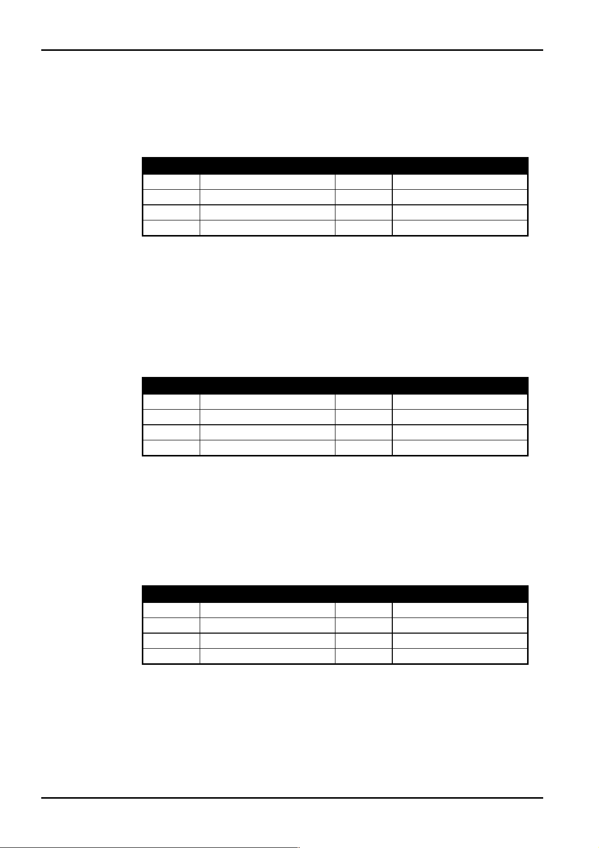
Solution Ultima 844 Zone Defaults
The default zone settings of the control panel are listed in the table below. Zones 1 – 4 may be
programmed to any of the available zone types. Zones 5 – 8 are limited to that they may only be
programmed to any 24 hour or keyswitch type. Refer to “Table 4: Available Zone Types” on page 25
for the different zone types that may be selected.
Zone No Zone Type Zone No Zone Type
1
2
3
4
Delay-1
Handover
Handover
Instant
5
6
7
8
Table 1: Zone Defaults For Solution Ultima 844
24 Hour Burglary
24 Hour Burglary
24 Hour Fire
24 Hour Tamper
Solution Ultima 862 Zone Defaults
The default zone settings of the control panel are listed in the table below. Zones 1 – 6 may be
programmed to any of the available zone types. Zones 7 and 8 are limited to that they may onl y be
programmed to any 24 hour or keyswitch type. Refer to “Table 4: Available Zone Types” on page 25
for the different zone types that may be selected.
Zone No Zone Type Zone No Zone Type
1
2
3
4
Delay-1
Handover
Handover
Handover
5
6
7
8
Table 2: Zone Defaults For Solution Ultima 862
Instant
Instant
24 Hour Fire
24 Hour Tamper
Solution Ultima 880 Zone Defaults
The default zone settings of the control panel are listed in the table below. Zones 1 – 8 may be
programmed to any of the available zone types. Refer to “Table 4: Available Zone Types” on page 25
for the different zone types that may be selected.
Zone No Zone Type Zone No Zone Type
1
2
3
4
Delay-1
Handover
Handover
Handover
5
6
7
8
Table 3: Zone Defaults For Solution Ultima 880
Instant
Instant
Instant
24 Hour Tamper
ISSUE162.DOC Electronics Design and Manufacturing Pty Limited

Introduction 25
Zone Types
There are thirteen different zone types to choose from when programming zones. These thirteen
different zone types are available for all
to Zone Programming on page 169 for more information on programming zones.
Zone Type Description Zone Type Description
0
1
2
3
4
5
6
7
Instant
Handover
Delay-1
Delay-2
Reserved
Reserved
24 Hour Medical
24 Hour Panic
Solution Ultima 844/862/880 control panels. Refer
8
9
10
11
12
13
14
15
Table 4: Available Zone Types
24 Hour Hold-Up
24 Hour Tamper
Reserved
Keyswitch
24 Hour Burglary
24 Hour Fire
Chime Only
Zone Not Used
Electronics Design and Manufacturing Pty Limited ISSUE162.DOC

26
Solution Ultima 844/862/880 Installation Manual
ISSUE162.DOC Electronics Design and Manufacturing Pty Limited

This section includes the following;
• CP5 Eight Zone LED Codepad
• CP5 Eight Zone LCD Codepad
• CP5 Master Partitioned LED Codepad
Codepad Indicators
28 Solution Ultima 844/862/880 Installation Manual
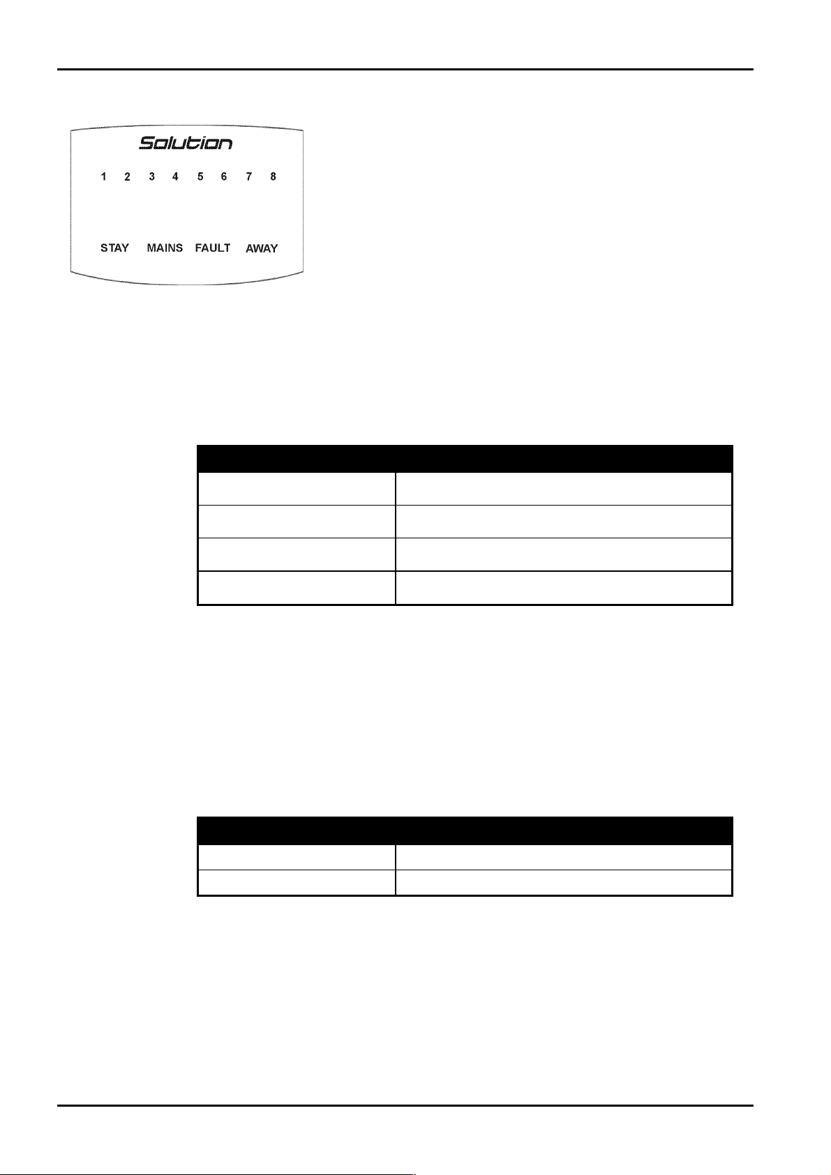
CP5 Eight Zone LED Codepad
The codepad is the communications interface between you and your alarm
system. T he codepad allows you to issue commands and offers both visual
and audible indications that guide you through th e general operation.
Figure 1: CP5 Eight Zone LED Codepad
(CP508)
Zone Indicators
The ZONE indicators are used to display the status of the zones. The following table lists the various
circumstances that the indicators will display (i.e. Zone Sealed, Zone Unsealed).
Indicator Definition
Flashing Fast
(0.25 Sec On – 0.25 Sec Off)
Flashing Slow
(1 Sec On – 1 Sec Off)
The codepad incorporates numerous indicators. There are
that are used to show the condition of each zo ne and four others for general
status. The following is a list of situations and the relevant indications that
will be seen.
On
Off
Zone Is Unsealed
Zone Is Sealed
Zone Is In Alarm Condition
Zone Is Manually Isolated
ZONE indicators
Table 5: Zone Indicators
AWAY Indicator
The AWAY indicator is used to display that the system is armed in AWAY Mode. The AWAY indicator
will also flash in unison with the
Functions are used.
Refer to page 40 for more information on the different methods on arming the system in AWAY
Mode.
Indicator Definition
On
Off
STAY indicator when Installer’s Programming Mode or Master Code
System Is Armed In AWAY Mode
System Is Not Armed In AWAY Mode
Table 6: AWAY Indicator
ISSUE162.DOC Electronics Design and Manufacturing Pty Limited
Codepad Indicators 29
STAY Indicator
The STAY indicator is used to display that the system is armed in STAY Mode 1 or STAY Mode 2.
The
STAY indicator will also flash in unison with the AWAY indicator when Installer’s Programming
Mode or Master Code Functions are used.
For the different methods of arming the system in STAY Mode 1, refer to page 42. Refer to Zone
Options 2 on page 179 for information on setting zones to be automatically isolated in STAY Mode 1.
For the method of arming the system i n STAY Mode 2, refer to page 45. Refer to Settin g STAY
Mode 2 Zones on page 71 when using the Installer Code or Setting STAY Mode 2 Zones on page 86
when using the Master Code.
Indicator Definition
On
Off
Flashing
Once Every 3 Seconds
System Is Armed In STAY Mode 1 Or STAY Mode 2
System Is Not Armed In STAY Mode
Zone Isolating Mode Or Setting STAY Mode 2 Zones
Day Alarm Status On/Off Indicator
Table 7: STAY Indicator
MAINS Indicator
The MAINS indicator is used to display that the systems AC mains supply is normal or has failed.
When programming numbers (i.e. Installer’s Programming Mode or Master Code Functions), the
MAINS indicator will illuminate when you program numbers between 10 and 15. The MAINS
indicator represents digit 10 plus the value of the illuminated zone indicator (e.g.: If you program a
twelve, the
MAINS indicator and zone 2 will illuminate).
Indicator Definition
On
Flashing
AC Mains Power Normal
AC Mains Failure
Table 8: MAINS Indicator
FAULT Indicator
The FAULT indicator is used to display that the system has detected a fault. Refer to Fault
Descriptions on page 53 for more information on sys tem faults.
Every time a new system faul t has been detected (e.g.: FAULT indicator flashing), the codepad will
begin to beep once every minute.
Pressing the
FAULT indicator on).
button once will cancel the once a minute beep and acknowledge the fault (e.g.:
Indicator Definition
On
Off
Flashing
Electronics Design and Manufacturing Pty Limited ISSUE162.DOC
There Is A System Fault That Needs To Be Rectified
The System Is Normal, There Are No Faults
There Is A System Fault Waiting To Be Acknowledged
Table 9: FAULT Indicator

30
Audible Indicators
In general, the audible indications given out by the codepad are as follows:
Indicator Definition
One Short Beep
Solution Ultima 844/862/880 Installation Manual
A Button Has Been Pressed On The Codepad Or End
Of Exit Time When Armed In Either STAY Mode 1 Or
STAY Mode 2
Two Short Beeps
Three Short Beeps
One Long Beep
One Short Beep Every Second
One Short Beep Every Two
Seconds
One Short Beep Every Minute
The System Has Accepted Your Code
The Requested Function Has Been Executed
Indicates The End Of Exit Time In AWAY Mode Or
The Requested Operation Has Been Denied Or Aborted
Walk Test Mode Is Currently Active Or Warning
Before Automatic Arming Takes Place
Telephone Monitor Mode Is Active
There Is A System Fault Waiting To Be Acknowledged
Table 10: Audible Indications
ISSUE162.DOC Electronics Design and Manufacturing Pty Limited
 Loading...