

Page 1

Solution 862
Installation Manual
ISSUE 1.30
Page 2

Page 3

This page has been included for you to cut out and insert into the spine
MA406I
Solution
of the folder
862
Installation
Manual
ISSUE 1.30
(61-2) 9672 1233
Page 4

Page 5

Solution 862
Installation Manual
Copyright 2001 by Electronics Design and Manufacturing Pty Limited,
SYDNEY, AUSTRALIA
Document Part Number MA406I
DOCUMENT ISSUE 1.30
Printed 10 May 2001
This documentation is provided to suit
Firmware Revision 1.00 – 1.09
Hardware Revision A - J
Alarm Link required = 2.74 or higher
Control Panel Software Version 1.00 – 1.09 = S406_V10
Copyright Notice
All rights reserved. No part of this publication may be reproduced, transmitted or stored in a retrieval system in any form or
by any means, electronic, mechanical, photocopying, recording, or otherwise, without the prior written permission of
Electronics Design and Manufacturing Pty Limited.
Trademarks
Throughout this document trademark names may have been used. Rather than put a trademark symbol in every occurrence
of a trademark name, we state that we are using the names only in an editorial fashion and to the benefit of the trademark
owner with no intention of infringement of the trademark.
Notice of Liability
Solution 862
Control Panel (CC406)
While every precaution has been taken in the preparation of this document, neither Electronics Design and Manufacturing
Pty Limited nor any of its official representatives shall have any liability to any person or entity with respect to any
liability, loss or damage caused or alleged to be caused directly or indirectly by the information contained in this book.
Electronics Design and Manufacturing Pty Limited reserves the right to make changes to features and specifications at any
time without prior notification in the interest of ongoing product development and improvement.
Page 6

Page 7

Table Of Contents
Introduction _____________________________________________________________________ 15
Introduction__________________________________________________________________________ 16
Features _____________________________________________________________________________ 17
Quick Start___________________________________________________________________________ 18
Zone Defaults ________________________________________________________________________________ 20
Zone Types __________________________________________________________________________________ 20
Programming____________________________________________________________________ 21
Programming_________________________________________________________________________ 22
Programming With The Remote Codepad _________________________________________________ 23
Programming With The Hand Held Programmer___________________________________________ 25
Programming With The Programming Key________________________________________________ 27
Programming Option Bits ______________________________________________________________ 28
Installer’s Programming Commands _____________________________________________________ 29
Command 958 - Enable/Disable Zone Status Mode ___________________________________________________ 30
Command 959 - Test Programming Key ___________________________________________________________ 31
Command 960 - Exit Installer's Programming Mode __________________________________________________ 33
Command 961- Reset Control Panel Back To Factory Default Settings____________________________________ 33
Command 962 - Copy Control Panel Memory To Programming Key _____________________________________ 34
Command 963 - Copy From Programming Key To Control Panel________________________________________ 35
Command 964 - Erase Programming Key __________________________________________________________ 36
Command 965 - Set Up Domestic Dialling Format ___________________________________________________ 37
Command 966 - Enable/Disable Automatic Stepping Of Locations_______________________________________ 38
Command 999 - Display Panel Type Or Software Version Number ______________________________________ 40
Disable Factory Default ________________________________________________________________________ 41
Defaulting The Control Panel ____________________________________________________________________ 42
Codepad Indicators _______________________________________________________________ 43
CP5 Eight Zone LED Codepad __________________________________________________________ 44
Zone Indicators _______________________________________________________________________________ 44
AWAY Indicator______________________________________________________________________________ 44
STAY Indicator_______________________________________________________________________________ 45
MAINS Indicator _____________________________________________________________________________ 45
FAULT Indicator _____________________________________________________________________________ 45
Audible Indicators_____________________________________________________________________________ 46
CP5 Eight Zone LCD Codepad __________________________________________________________ 47
Zone Indicators _______________________________________________________________________________ 47
AWAY Indicator______________________________________________________________________________ 47
STAY Indicator_______________________________________________________________________________ 48
System Disarmed _____________________________________________________________________________ 48
MAINS Indicator _____________________________________________________________________________ 48
Zone Isolating Mode ___________________________________________________________________________ 48
FAULT Indicator _____________________________________________________________________________ 49
Programming Mode ___________________________________________________________________________ 49
Off Indicator/Zone Sealed_______________________________________________________________________ 49
On Indicator/Zone In Alarm _____________________________________________________________________ 49
Audible Indicators_____________________________________________________________________________ 50
System Operations ________________________________________________________________ 51
System Operations_____________________________________________________________________ 52
Arming The System In AWAY Mode _____________________________________________________________ 52
Forced Arming _____________________________________________________________________________ 52
Disarming The System From AWAY Mode_________________________________________________________ 53
Page 8

Arming The System In STAY Mode 1_____________________________________________________________ 54
Entry Guard Timer For STAY Mode ____________________________________________________________ 54
Forced Arming _____________________________________________________________________________ 55
Disarming The System From STAY Mode 1 ________________________________________________________ 56
Arming The System In STAY Mode 2_____________________________________________________________ 57
Entry Guard Timer For STAY Mode ____________________________________________________________ 57
Forced Arming _____________________________________________________________________________ 57
Disarming The System From STAY Mode 2 ________________________________________________________ 58
Codepad Duress Alarm_________________________________________________________________________ 59
Codepad Panic Alarm__________________________________________________________________________ 59
Codepad Fire Alarm ___________________________________________________________________________ 59
Codepad Medical Alarm________________________________________________________________________ 59
Isolating Zones ________________________________________________________________________ 60
Standard Isolating ___________________________________________________________________________ 61
Code To Isolate_____________________________________________________________________________ 62
Fault Analysis Mode____________________________________________________________________ 63
Fault Descriptions_____________________________________________________________________________ 64
Low Battery _______________________________________________________________________________ 64
Date and Time______________________________________________________________________________ 64
Sensor Watch ______________________________________________________________________________ 64
Horn Speaker Monitor _______________________________________________________________________ 64
Telephone Line Fault ________________________________________________________________________ 64
2
E
Fault ___________________________________________________________________________________ 64
Fuse Fail __________________________________________________________________________________ 65
Communication Failure ______________________________________________________________________ 65
AC Mains Failure ___________________________________________________________________________ 66
Remote Radio Transmitter Operations ________________________________________________ 67
Remote Radio Transmitter Operations ____________________________________________________ 68
Indications Upon Remote Radio Transmitter Operations_______________________________________________ 68
Remote Radio User Code Priority Levels___________________________________________________________ 68
Changing Or Deleting Remote Radio User Codes ____________________________________________________ 69
2 Channel Radio Remote Hand Held Transmitter Operations ___________________________________________ 71
Arming In AWAY Mode _____________________________________________________________________ 71
Disarming From AWAY Mode ________________________________________________________________ 71
Arming In STAY Mode 1_____________________________________________________________________ 71
Disarming From STAY Mode 1 ________________________________________________________________ 71
Panic Alarm _______________________________________________________________________________ 71
4 Channel Radio Remote Hand Held Transmitter Operations ___________________________________________ 72
Arming In AWAY Mode _____________________________________________________________________ 72
Disarming From AWAY Mode ________________________________________________________________ 72
Arming In STAY Mode 1_____________________________________________________________________ 72
Disarming From STAY Mode 1 ________________________________________________________________ 72
Panic Alarm _______________________________________________________________________________ 72
Turning Output 1 ON ________________________________________________________________________ 73
Turning Output 1 OFF _______________________________________________________________________ 73
Turning Output 2 ON ________________________________________________________________________ 73
Turning Output 2 OFF _______________________________________________________________________ 73
System Functions _________________________________________________________________ 75
System Functions ______________________________________________________________________ 76
Installer Code Functions ________________________________________________________________________ 76
Reserved __________________________________________________________________________________ 76
Set The Number Of Days Until The First Test Report _______________________________________________ 77
Changing Domestic Phone Numbers ____________________________________________________________ 78
Change Telco Arm/Disarm Sequence ____________________________________________________________
Setting STAY Mode 2 Zones __________________________________________________________________ 85
Satellite Siren Service Mode___________________________________________________________________ 86
Turning Telephone Monitor Mode On/Off________________________________________________________ 87
Walk Test Mode ____________________________________________________________________________ 87
Event Memory Recall Mode___________________________________________________________________ 88
Reserved __________________________________________________________________________________ 88
80
Page 9

Master Code Functions_________________________________________________________________ 89
Reserved __________________________________________________________________________________ 89
Changing and Deleting User Codes _____________________________________________________________ 90
Changing and Deleting Remote Radio User Codes__________________________________________________ 92
Changing Domestic Phone Numbers ____________________________________________________________ 94
Change Telco Arm/Disarm Sequence ____________________________________________________________ 96
Setting STAY Mode 2 Zones _________________________________________________________________ 101
Turning Outputs On/Off _____________________________________________________________________ 102
Setting The Date and Time ___________________________________________________________________ 104
Walk Test Mode ___________________________________________________________________________ 105
Event Memory Recall Mode __________________________________________________________________ 106
Reserved _________________________________________________________________________________ 106
Hold Down Functions _________________________________________________________________ 107
Arm The System In AWAY Mode _____________________________________________________________ 107
Arm The System In STAY Mode 1_____________________________________________________________ 107
Arm The System In STAY Mode 2_____________________________________________________________ 107
Horn Speaker Test__________________________________________________________________________ 107
Bell Test _________________________________________________________________________________ 108
Strobe Test _______________________________________________________________________________ 108
Turning Day Alarm On and Off _______________________________________________________________ 108
Fault Analysis Mode ________________________________________________________________________ 109
Initiate A Modem Call ______________________________________________________________________ 109
Reset Latching Outputs ______________________________________________________________________ 109
Codepad Buzzer Tone Change ________________________________________________________________ 110
Send Test Report___________________________________________________________________________ 110
Remote System__________________________________________________________________ 111
Operations Via Telephone_________________________________________________________ 111
Remote Arming Via The Telephone _____________________________________________________ 112
Alarm Link Operations ___________________________________________________________ 113
Alarm Link Software _________________________________________________________________ 114
Remote Connect _____________________________________________________________________________ 114
Remote Connect With Customer Control ________________________________________________________ 114
Remote Connect Without Call Back Verification __________________________________________________ 115
Remote Connect With Call Back Verification ____________________________________________________ 115
Direct Connect ____________________________________________________________________________ 116
Alarm Link Options __________________________________________________________________________ 117
Enable Upload/Download Via Alarm Link_______________________________________________________ 117
Enable Alarm Link Call Back _________________________________________________________________ 117
Terminate Alarm Link Connection On Alarm ____________________________________________________ 117
Use External Modem Module (CC811) For Alarm Link Operations ___________________________________ 117
Domestic Dialling _______________________________________________________________ 119
Domestic Dialling Format______________________________________________________________ 120
Domestic Dialling Function ____________________________________________________________________ 120
Acknowledge Domestic Dialling ______________________________________________________________ 120
Setting Up and Programming Domestic Reporting___________________________________________________ 121
Disable Domestic Dialling ___________________________________________________________________ 122
Dialler Reporting Formats ________________________________________________________ 123
Transmission Formats ________________________________________________________________ 124
Contact ID Format ___________________________________________________________________________ 124
Point ID Codes ______________________________________________________________________________ 125
4+2 Reporting Format_________________________________________________________________________ 126
Basic Pager Reporting Format __________________________________________________________________ 127
Basic Pager Display Information________________________________________________________ 128
Subscriber ID Number ________________________________________________________________________ 128
Zone Status _________________________________________________________________________________ 128
System Status _______________________________________________________________________________ 128
Page 10

Dialler Information ______________________________________________________________ 129
Dialler Information ___________________________________________________________________ 130
Primary Telephone Number For Receiver 1________________________________________________________ 131
Secondary Telephone Number For Receiver 1______________________________________________________ 131
Handshake Tone For Receiver 1_________________________________________________________________ 132
Transmission Format For Receiver 1 _____________________________________________________________ 133
Subscriber ID Number For Receiver 1 ____________________________________________________________ 133
Primary Telephone Number For Receiver 2________________________________________________________ 134
Secondary Telephone Number For Receiver 2______________________________________________________ 134
Handshake Tone For Receiver 2_________________________________________________________________ 135
Transmission Format For Receiver 2 _____________________________________________________________ 136
Subscriber ID Number For Receiver 2 ____________________________________________________________ 136
Dialling Format______________________________________________________________________________ 137
Reserved ___________________________________________________________________________________ 137
Telco Arming Sequence _______________________________________________________________________ 138
Telco Arming – Call Forward Immediate On_____________________________________________________ 138
Telco Arming – Call Forward No Answer On ____________________________________________________ 138
Telco Disarming Sequence _____________________________________________________________________ 139
Telco Arming – Call Forward Immediate Off ____________________________________________________ 139
Telco Arming – Call Forward No Answer Off ____________________________________________________ 139
Call Back Telephone Number___________________________________________________________________ 139
Ring Count _________________________________________________________________________________ 140
Answering Machine Bypass ____________________________________________________________________ 140
Telephone Line Fault Options __________________________________________________________________ 141
Display FAULT Indicator When Telephone Line Fails _____________________________________________ 141
Sound Alarm When System Is Armed __________________________________________________________ 141
Sound Alarm When System Is Disarmed ________________________________________________________ 141
Reserved _________________________________________________________________________________ 141
Ring Burst Time _____________________________________________________________________________ 142
Dialler Options __________________________________________________________________ 143
Programming Option Bits ______________________________________________________________ 144
Dialler Options 1 ____________________________________________________________________________ 145
Dialler Reporting Functions Allowed___________________________________________________________ 145
Disabled = Disable All Dialler Reporting Functions _______________________________________________ 145
Remote Arming Via The Telephone Allowed ____________________________________________________ 145
Answering Machine Bypass Only When Armed __________________________________________________ 145
Use Bell 103 For FSK Format (Disabled = CCITT V21)____________________________________________ 145
Dialler Options 2 ____________________________________________________________________________ 146
Open/Close Reports Only If Previous Alarm _____________________________________________________ 146
Open/Close Reports For STAY Mode 1 and STAY Mode 2 _________________________________________ 146
Delay Siren Until Transmission Complete _______________________________________________________ 146
Extend Time To Wait For Handshake From 30 - 55 Seconds ________________________________________ 146
Dialler Options 3 ____________________________________________________________________________ 147
Set DTMF Dialling Pulses To 1 Digit/Second ____________________________________________________ 147
Reserved _________________________________________________________________________________ 147
Change Decadic Dialling To 60/40_____________________________________________________________ 147
Reserved _________________________________________________________________________________ 147
Alarm Link Options __________________________________________________________________________ 148
Upload/Download Allowed __________________________________________________________________ 148
Call Back Phone Number Required For Upload/Download __________________________________________ 148
Terminate Upload/Download On Alarm ________________________________________________________ 148
External Modem Module (CC811) Required For Upload/Download___________________________________ 148
User Codes _____________________________________________________________________ 149
Access Codes _________________________________________________________________________ 150
Installer Code _______________________________________________________________________________ 150
User Codes _________________________________________________________________________________ 151
User Codes __________________________________________________________________________ 152
User Code Priority ___________________________________________________________________________ 153
Page 11

Zone Information _______________________________________________________________ 155
Day Alarm Zones ____________________________________________________________________________ 156
Day Alarm Resetting________________________________________________________________________ 156
Day Alarm Latching ________________________________________________________________________ 156
Day Alarm Operation _________________________________________________________________________ 157
EOL Resistor Value __________________________________________________________________________ 158
Connections Of Split EOL Resistors Using N/C Contacts _____________________________________________ 159
Connections Of Split EOL Resistors Using N/O Contacts _____________________________________________ 160
Zone Programming ___________________________________________________________________ 161
Zone Operating Information ____________________________________________________________________
Zone Options________________________________________________________________________________
Zone Reporting Information ____________________________________________________________________
Solution 862 Zones Defaults____________________________________________________________________
Zone Types _________________________________________________________________________________
Instant Zone_______________________________________________________________________________
Handover Zone ____________________________________________________________________________
Delay-1 Zone______________________________________________________________________________
Delay-2 Zone______________________________________________________________________________
Reserved _________________________________________________________________________________
Reserved _________________________________________________________________________________
24 Hour Medical ___________________________________________________________________________
24 Hour Panic _____________________________________________________________________________
24 Hour Hold-Up __________________________________________________________________________
24 Hour Tamper ___________________________________________________________________________
Reserved _________________________________________________________________________________
Keyswitch Zone ___________________________________________________________________________
24 Hour Burglary Zone ______________________________________________________________________
24 Hour Fire Zone__________________________________________________________________________
Chime Zone_______________________________________________________________________________
Zone Not Used ____________________________________________________________________________
Zone Pulse Count ____________________________________________________________________________
Zone Pulse Count Handover __________________________________________________________________
Zone Pulse Count Time________________________________________________________________________
Zone Options 1 ______________________________________________________________________________
Lockout Siren & Lockout Dialler ______________________________________________________________
Delay Alarm Reporting ______________________________________________________________________
Silent Alarm ______________________________________________________________________________
Sensor Watch _____________________________________________________________________________
Keyswitch Zone Options_______________________________________________________________________
Latching Arm and Disarm In AWAY Mode______________________________________________________
Latching Arm In AWAY Mode _______________________________________________________________
Latching Disarm From AWAY Mode, STAY Mode 1 Or STAY Mode 2 _______________________________
Latching Arm and Disarm In STAY Mode 1 _____________________________________________________
Latching Arm In STAY Mode 1 _______________________________________________________________
Latching Disarm From STAY Mode 1 Or STAY Mode 2 ___________________________________________
Momentary Arm and Disarm In AWAY Mode ___________________________________________________
Momentary Arm In AWAY Mode _____________________________________________________________
Momentary Disarm From AWAY Mode, STAY Mode 1 Or STAY Mode 2_____________________________
Momentary Arm and Disarm In STAY Mode 1 ___________________________________________________
Momentary Arm In STAY Mode 1_____________________________________________________________
Momentary Disarm From STAY Mode 1 Or STAY Mode 2 _________________________________________
Zone Options 2 ______________________________________________________________________________
Isolate In STAY Mode 1 _____________________________________________________________________
Zone Isolation Allowed______________________________________________________________________
Forced Arming Allowed _____________________________________________________________________
Zone Restore Report ________________________________________________________________________
Zone Reporting Information ____________________________________________________________________
Zone Report Code __________________________________________________________________________
Zone Dialler Options________________________________________________________________________
Swinger Shutdown Count For Siren ______________________________________________________________
Swinger Shutdown Count For Dialler_____________________________________________________________
161
161
161
162
162
162
162
163
163
163
163
163
163
163
163
163
164
164
164
164
164
165
165
166
167
167
167
168
168
169
169
169
169
169
169
169
170
170
170
170
170
170
171
171
171
171
171
172
172
172
173
174
Page 12

System Reporting Information _____________________________________________________ 175
Reporting Information_________________________________________________________________ 176
Zone Status – Bypass Reports __________________________________________________________________ 176
Zone Status – Trouble Reports __________________________________________________________________ 177
Zone Status – Sensor Watch Reports _____________________________________________________________ 178
Zone Status – Alarm Restore Code_______________________________________________________________ 178
Zone Status Reporting Options__________________________________________________________________ 178
Open/Close Reports __________________________________________________________________________ 179
Open/Close Reporting Options__________________________________________________________________ 179
Codepad Duress Report _______________________________________________________________________ 180
Codepad Panic Report ________________________________________________________________________ 180
Codepad Fire Report__________________________________________________________________________ 181
Codepad Medical Report ______________________________________________________________________ 181
Codepad Reporting Options ____________________________________________________________________ 182
System Status – Fuse Fail Report ________________________________________________________________ 182
System Status – Fuse Fail Restore Report _________________________________________________________ 182
System Status – AC Fail Report _________________________________________________________________ 183
System Status – AC Fail Restore Report __________________________________________________________ 183
System Status - Low Battery Report______________________________________________________________ 184
System Status - Low Battery Restore Report _______________________________________________________ 184
System Status - Access Denied__________________________________________________________________ 185
Code Retries ______________________________________________________________________________ 185
System Status Reporting Options ________________________________________________________________ 186
Test Reporting Time__________________________________________________________________________ 187
Test Reporting Dialler Options__________________________________________________________________ 187
Programmable Outputs ___________________________________________________________ 189
Outputs _____________________________________________________________________________ 190
Output Defaults______________________________________________________________________________ 190
Default For Strobe ___________________________________________________________________________ 190
Default For Entry/Exit ________________________________________________________________________ 190
Redirecting Outputs To The Codepad Buzzer ______________________________________________________ 191
Output Event Types __________________________________________________________________________ 192
Output Polarity ______________________________________________________________________________ 199
Output Not Used___________________________________________________________________________ 199
Normally Open, Going Low __________________________________________________________________ 199
Normally Open, Pulsing Low _________________________________________________________________ 199
Normally Open, One Shot Low _______________________________________________________________ 199
Normally Open, One Shot Low With Retrigger ___________________________________________________ 199
Normally Open, One Shot Low With Reset ______________________________________________________ 199
Normally Open, One Shot Low With Alarm _____________________________________________________ 200
Normally Open, Latching Low________________________________________________________________ 200
Normally Low, Going Open __________________________________________________________________ 200
Normally Low, Pulsing Open _________________________________________________________________ 200
Normally Low, One Shot Open _______________________________________________________________ 200
Normally Low, One Shot Open With Retrigger ___________________________________________________ 200
Normally Low, One Shot Open With Reset ______________________________________________________ 200
Normally Low, One Shot Open With Alarm _____________________________________________________ 200
Normally Low, Latching Open________________________________________________________________ 200
Timing Of Outputs ___________________________________________________________________________ 201
Pulsing Polarities ____________________________________________________________________________ 201
One Shot Polarities ___________________________________________________________________________ 202
System Event Timers _____________________________________________________________ 203
System Event Timers __________________________________________________________________ 204
Programming Entry/Exit Timers ________________________________________________________________ 204
Entry Timer 1 _______________________________________________________________________________ 204
Entry Timer 2 _______________________________________________________________________________ 204
Exit Time __________________________________________________________________________________ 205
Entry Guard Timer For STAY Mode _____________________________________________________________ 205
Delay Alarm Reporting Time ___________________________________________________________________ 205
Sensor Watch Time __________________________________________________________________________ 206
Codepad Lockout Time _______________________________________________________________________ 206
Page 13

Siren Run Time ______________________________________________________________________________ 207
Siren Sound Rate_____________________________________________________________________________ 207
Auto Arming Pre-Alert Timer___________________________________________________________________
Auto Arming Time ___________________________________________________________________________ 208
Auto Disarming Time _________________________________________________________________________ 209
Kiss-Off Wait Time __________________________________________________________________________
Reserved ___________________________________________________________________________________ 209
System Time ________________________________________________________________________________ 210
System Date ________________________________________________________________________________ 211
Setting The Date and Time ___________________________________________________________________ 211
208
209
System and Consumer Options _____________________________________________________ 213
Programming Option Bits _____________________________________________________________ 214
System Options 1 ____________________________________________________________________________ 215
EDM Smart Lockout Allowed ________________________________________________________________
Horn Speaker Monitor_______________________________________________________________________ 215
Strobe Indications For Radio Arm/Disarm _______________________________________________________ 215
Horn Speaker Beeps For Radio Arm/Disarm _____________________________________________________ 215
System Options 2 ____________________________________________________________________________ 216
Codepad Panic To Be Silent __________________________________________________________________ 216
Codepad Fire To Be Silent ___________________________________________________________________
Codepad Medical To Be Silent ________________________________________________________________ 216
Access Denied (Code Retries) To Be Silent ______________________________________________________ 216
System Options 3 ____________________________________________________________________________ 217
AC Fail After 1 Hour (Disabled = After 2 Minutes) ________________________________________________
Ignore AC Fail ____________________________________________________________________________
Zone Pulse Count Handover __________________________________________________________________ 217
Handover Delay To Be Sequential _____________________________________________________________
System Options 4 ____________________________________________________________________________ 218
Panel To Power Up Disarmed_________________________________________________________________
Arm/Disarm Tracking On Power Up ___________________________________________________________
Internal Crystal To Keep Time ________________________________________________________________ 218
Keyswitch Interface, Night Arm Station Or RE005 Installed _________________________________________
Consumer Options 1 __________________________________________________________________________ 219
Test Reports Only When Armed_______________________________________________________________
Test Report After Siren Reset _________________________________________________________________ 219
Auto Arm In STAY Mode 1 __________________________________________________________________ 219
STAY Indicator To Display Day Alarm Status____________________________________________________ 219
Consumer Options 2 __________________________________________________________________________ 220
Codepad Display Extinguish After 60 Seconds ___________________________________________________
Single Button Arming Allowed (AWAY Mode/STAY Mode 1 & 2)___________________________________ 220
Single Button Disarming Allowed (STAY Mode 1 & 2) ____________________________________________
Alarm Memory Reset On Disarm ______________________________________________________________ 220
Consumer Options 3 __________________________________________________________________________ 221
Codepad Fault Alarm Beeps __________________________________________________________________ 221
Use Digit 3 For Codepad Duress Instead Of Digit 9________________________________________________
Alarms Activate Sirens & Strobe Ouputs In STAY Mode 1 & 2 ______________________________________ 221
Reserved _________________________________________________________________________________
Radio Input Options __________________________________________________________________________
Radio Receiver (WE800) ____________________________________________________________________
Latching Keyswitch Input ____________________________________________________________________
Momentary Keyswitch Input__________________________________________________________________ 222
215
216
217
217
217
218
218
218
219
220
220
221
221
222
222
222
Optional Equipment _____________________________________________________________ 223
Optional Equipment __________________________________________________________________ 224
Terminals and Descriptions _______________________________________________________ 229
Terminal Definitions and Descriptions ___________________________________________________ 230
Glossary Of Terms ___________________________________________________________________
Solution 862 Wiring Diagram __________________________________________________________ 234
Solution 862 Component Overlay _______________________________________________________ 235
Telecom Connection Diagrams _________________________________________________________ 236
231
Page 14

Appendices _____________________________________________________________________ 237
Appendix A __________________________________________________________________________ 238
Telephone Anti-Jamming ______________________________________________________________________ 238
Appendix B __________________________________________________________________________ 239
Test Reports Only When Armed ________________________________________________________________ 239
Specifications ___________________________________________________________________ 241
Warranty Statement___________________________________________________________________ 242
Year 2000 Compliance _________________________________________________________________ 242
Specifications ________________________________________________________________________ 243
Software Version Number _____________________________________________________________________ 243
Advice To Users _____________________________________________________________________________ 243
New Zealand Telepermit Notes _________________________________________________________________ 244
Programming Sheets _____________________________________________________________ 245
Index __________________________________________________________________________ 255
Page 15

This section includes the following;
•
Introduction
•
Features
•
Quick Start
•
Zone Defaults
•
Zone Types
Introduction
Page 16

16
Introduction
Congratulations on selecting the
you can obtain the most from your unit, we suggest that you take the time to read through this
manual and familiarise yourself with the numerous outstanding operating and installation
features of this system.
You will notice that in all aspects of planning, engineering, styling, operation, convenience and
adaptability, we have sought to anticipate your every possible requirement. Programming
simplicity and speed have been some of the major considerations and we believe that our
objectives in this area have been more than satisfied.
Solution 862
Solution 862
Installation Manual
control panel for your installation. So that
This installation manual will explain all aspects of programming the
Solution 862
control
panel from factory default to final commissioning. All system parameters and options are
detailed, however, suitability is left up to the individual. Every control panel can be tailored to
meet all requirements quickly and easily. The programming simplicity will make your
installation quick, accurate and rewarding each and every time.
Solution
The
range of control panels are very popular amongst thousands of people
throughout many countries of the world, a ll who have various levels of technical aptitude and
ability. We have tried to aim this installation manual to all levels of readers.
As the
Solution
control panels continue to be improved over the years, they have become
very powerful. Some of its early first-time users have advanced to true "power users" and we
need to address their needs too, while maintaining the simplicity of the manual and the product.
ISSUE130 Electronics Design and Manufacturing Pty Limited
Page 17

Introduction 17
Features
Solution 862
The
provide you with more useful features and superior reliability and performance.
Following is a list of the main features that the control panel will provide.
‹ Eight Programmable User Codes (1 – 8)
‹ Eight Remote Radio User Codes (9 – 16)
‹ Six Programmable Burglary Zones
‹ Two Programmable 24 Hour Zones
‹ Dual Reporting
‹ On-Board Line Fault Module
‹ Telco Arming/Disarming Sequence
‹ Automatic Arming
‹ Automatic Disarming
‹ Codepad Duress, Panic, Fire, Medical Alarms
‹ STAY Mode and AWAY Mode Operation
security system uses the very latest in microprocessor technology to
‹ Upload/Download Programmable
‹ Dynamic Battery Testing
‹ Entry and Exit Warning Beeper
‹ Remote Arming
‹ Answering Machine Bypass
‹ AC Fail and System Fault Indicators
‹ Monitored Siren Output
‹ Strobe Output
‹ Relay Output
‹ Sep a r ate Fire Alarm Sound
‹ EDMSAT – Satellite Siren Compatible
‹ Zone Lockout
‹ Se nsor Watch
‹ Day Alarm
‹ Event Memory Recall
‹ Walk Test Mode
‹ Delayed Reporting
Electronics Design and Manufacturing Pty Limited ISSUE130
Page 18

18
Quick Start
The following steps will allow you to use the
default values. The default values allow the control panel to communicate in the Contact ID
format. If you are not familiar to programming the
suggest that you first read information contained in the programming section beginning on
page 22.
After all wiring has been completed, connect the AC plug pack to the control panel.
1.
Both the
display to indicate that the AC mains supply has been connected. T he
displays that the system is now armed in the AWAY Mode. If any 24 hour zones are
unsealed at the time the system is powered up, the siren, strobe and bell outputs will
activate into alarm and the corresponding zone indicator will flash.
MAINS
and
Solution 862
Solution
AWAY
indicators will illuminate. The
Solution 862
control panel with the factory
range of control panels, we
Installation Manual
MAINS
indicator will
AWAY
indicator
Enter the default Master Code
2.
system and to reset any alarm that may have occurred during the system power up. The
AWAY
any zone indicators are flashing, this would indicate that an alarm had occurred on that
zone. If a zone indicator is constantly illuminated, this would indicate that the zone is
unsealed.
The back-up battery should now be connected.
3.
Enter the factory default Installer Code
4.
beeps will be heard and the
to indicate that you have now entered Installer’s Programming Mode. When entering
Installer’s Programming Mode, you will be automatically positioned at “LOCATION
000”, the beginning of the Primary Telephone Number For Receiver 1.
Enter the Primary Telephone Number followed by the Secondary Telephone Number
5.
and the Subscriber ID Number for Receiver 1. Refer to Dialler Information on page
130 for more information.
Remember that when programming a zero in the telephone numbers of Receiver 1 and
Receiver 2, a zero must be programmed as a ten. Programming a zero in the telephone
number will indicate the end of the dialling sequence. A zero must be programmed as a
zero in all other locations other than the telephone numbers for Receiver 1, Receiver 2
and the Call Back Telephone number, unless otherwise stated.
indicator will extinguish to indicate that the system has now been disarmed. If
2580
STAY
and
followed by the button to disarm the
1234
AWAY
followed by the button. Two
indicators will now flash simultaneously
Set the time for the test reports if required. Any other programming changes required
6.
may also be made, otherwise the factory default settings will be used. Refer to Test
Reporting Time on page 187 for more information on programming test reports.
Enter Installer’s Command
7.
Programming Mode. Two beeps will be heard and the
extinguish. The system has now returned to the disarmed state and is now ready for use.
Refer to Installer’s Programming Commands on page 29 for more information.
Use the Master Code to set the date and time. Refer to Set The Date and Time on page
8.
19 for more information.
ISSUE130 Electronics Design and Manufacturing Pty Limited
960
followed by the button to exit Installer’s
STAY
and
AWAY
indicators will
Page 19
Introduction 19
How To Set The Date and Time
Enter your
1.
Three beeps will be heard and the
Enter the day, month, year, hour and minute using the (DD, MM, YY, HH, MM) format
2.
(i.e. DD = Day of the month, MM = Month of the year, YY = Current year, HH = Hour
of the day, MM = Minute of the day).
Please note that when programming the hour of the day, you will need to use 24:00 hour
format.
Press the
3.
Two beeps will be heard and the
beeps is heard, an error was made when entering the date and time.
+
DD+ MM+ YY+ HH+ MM
button when finished.
followed by 6and the button.
STAY
STAY
and
and
+
AWAY
indicators will begin to flash.
AWAY
indicators will extinguish. If a long
+
6
+
Example
If the date and time needs to be set for the 1st January 1997 at 10:30 PM, program the
date and time as follows;
2580+ 6
+
0+ 1+ 0+ 1+ 9+ 7+ 2+ 2+ 3+ 0
+
+
Electronics Design and Manufacturing Pty Limited ISSUE130
Page 20

20
Zone Defaults
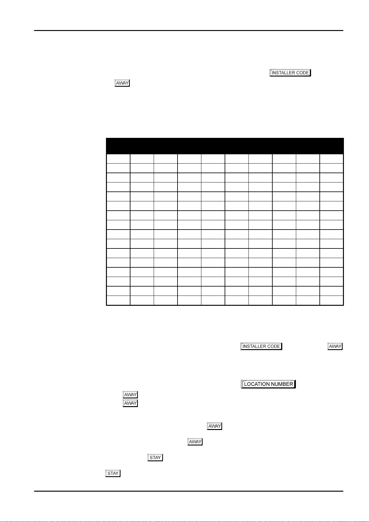
The default zone settings of the control panel are listed in the table below. Zones 1 – 6 may be
programmed to any of the available zone types. Zones 7 and 8 are limited to that they may
only be programmed to any 24 hour or keyswitch type. Refer to “Table 2: Available Zone
Types” on page 20 for the different zone types that may be selected.
Zone No Zone Type Zone No Zone Type
1
2
3
4
Delay-1
Handover
Handover
Handover
Zone Types
There are thirteen different zone types to choose from when programming zones. These
thirteen different zone types are available for all
Zone Programming on page 161 for more information on programmi ng zones.
Solution 862
5
6
7
8
Table 1: Zone Defaults For Solution 862
Solution 862
Instant
Instant
24 Hour Fire
24 Hour Tamper
Installation Manual
control panels. Refer to
Zone Type Description Zone Type Description
0
1
2
3
4
5
6
7
Instant
Handover
Delay-1
Delay-2
Reserved
Reserved
24 Hour Medical
24 Hour Panic
8
9
10
11
12
13
14
15
Table 2: Available Zone Types
24 Hour Hold-Up
24 Hour Tamper
Reserved
Keyswitch
24 Hour Burglary
24 Hour Fire
Chime Only
Zone Not Used
ISSUE130 Electronics Design and Manufacturing Pty Limited
Page 21

This section includes the following;
•
Programming
•
Programming With The Remote Codepad
•
Programming With The Hand Held Programmer
•
Programming With The Programming Key
•
Programming Option Bits
•
Installer’s Programming Commands
•
Disable Factory Default
•
Defaulting The Control Panel
Programming
Page 22

22
Programming
The programming options of the control panel are stored in a non-volatile EPROM. This
memory will hold all the relevant configuration and user specific data even during a total
power loss.
The data retention time is as long as ten years without power; therefore, no reprogramming will
be required after powering the control panel down.
The data can be changed as many times as required without the need for any additional
specialised equipment. This memory is laid out in numerous locations, each of which holds the
data for a specific function.
15 is the maximum value that can be programmed into any location.
In general, the entire programming sequence will consist of nominating the required location
number and then enter or change the current data. You will repeat this procedure until all the
data has been programmed to suit your requirements. The factory default settings have been
selected for reporting to the monitoring station in the Contact ID Format.
Solution 862
Installation Manual
Example
LOCATION 000 - 015
The Installers Code only gives access to the Installer's Programming Mode and does NOT arm
and disarm the system. Installer’s Programming Mode can not be entered when the system is
armed, or at any time during siren run time.
Programming of the
three methods.
Solution 862
•
Remote Codepad
Hand Held Programmer (CC814)
•
Alarm Link Upload/Download Software (CC816)
•
control panel can be carried out via any of the following
Primary Telephone Number For Receiver 1
0000000000000000
LOCATION 000
LOCATION 001
ISSUE130 Electronics Design and Manufacturing Pty Limited
LOCATION 004
LOCATION 015
Page 23
Programming 23
Programming With The Remote Codepad
When programming the control panel via the remote codepad, the system must be in the
disarmed state with no alarm memory present.
To access the Installer’s Programming Mode, enter the four digit followed by
the button. The factory default Installer Code is
AWAY
and both the
entered Installer’s Programming Mode.
When entering Installer’s Programming Mode, you will be automatically positioned at
“LOCATION 000”, the beginning of the Primary Telephone Number for Receiver 1.
and the
STAY
indicators will flash simultaneously to indicate that you have
1234
. Two beeps will be heard
Data
Value
0
1
2
3
4
5
6
7
8
9
10
11
12
13
14
15
Zone 1
Indicator
V
V V
V V
Zone 2
Indicator
V
V V
Zone 3
Indicator
V
V V
Table 3: Codepad Indicators When Programming
Zone 4
Indicator
V
V V
Zone 5
Indicator
V
V V
Zone 6
Indicator
V
Zone 7
Indicator
V
Indicator
Zone 8
Indicator
V
MAINS
V
Example
To access Installer’s Programming Mode, enter the followed by the
button. Two beeps will be heard and both the
simultaneously to indicate that you have entered Installer’s Programming Mode. The codepad
indicators will display the current data stored in the first location (LOCATION 000).
To move to another programming location, enter the required followed
by the button. T he data of the new location will now be displayed (e.g.
by the button will automatically step you to the beginning of the Subscriber ID Number
for Receiver 1).
To move to the next location, press the button. T his will step you to the next location
and the data in that location will be displayed (e.g. If you are currently positioned at
“LOCATION 034”, pressing the button will step you to “LOCATION 035”).
If you press the
step back one location (e.g. If you are positioned at “LOCATION 035” and you press the
button, you will step back one location to LOCATION 034).
Electronics Design and Manufacturing Pty Limited ISSUE130
button without previously entering a location number, the system will
AWAY
and the
STAY
indicators will flash
34
followed
Page 24

24
To change data in the current location, enter the new value (0 – 15) followed by the
button. This will store the new data into the location and still leave you positioned at the same
location. You will notice that the new information programmed will be displayed on the
codepad indicators (e.g. If you enter the value
MAINS
4 and the
indicator will illuminate).
Solution 862
followed by the button, both
14
Installation Manual
ZONE
To move to the next location, press the
now be displayed.
To exit the Installer’s Programming Mode, enter command
button. Two beeps will be heard and the
system will now return to the disarmed state and is now ready for use.
Refer to Installer’s Programming Commands on page 29 for further information on commands
that can be performed during access of Installer’s Programming Mode.
button. The data in the next locations data will
followed by the
STAY
and
960
AWAY
indicators will extinguish. The
ISSUE130 Electronics Design and Manufacturing Pty Limited
Page 25
Programming 25
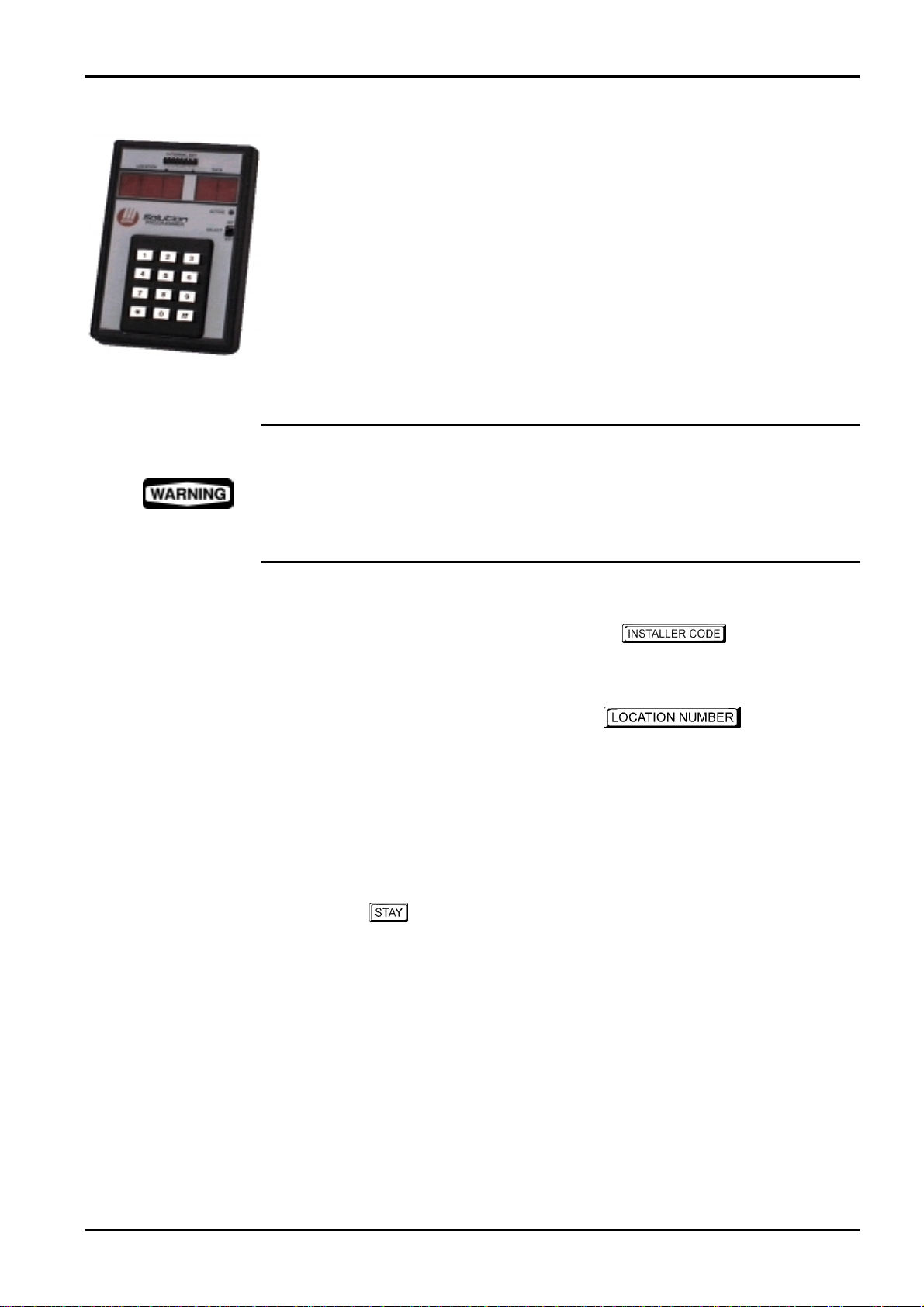
Programming With The Hand Held Programmer
The Hand Held Programmer (CC814) has five, seven segment displays. The three seven
segment displays on the left display the current location number and the two seven segment
displays on the right display the data for the location currently being displayed.
To connect the hand held programmer, locate the socket marked PROGRAMMING KEY
found at the top of the PCB (printed circuit board) next to the Auxiliary Module socket.
Observe the triangular markings on the PCB and line them up with the markings on the
hand held programmers connecting socket.
When the hand held programmer is correctly connected onto the printed circuit board, one
beep will be heard and four centre bars on the hand held programmer will illuminate with
either an 'A' or 'U' suffix to indicate the system is armed or unarmed. Only when the
Installer's Programming Mode has been accessed will any numerals appear on the display.
When connecting the hand held programmer to the control panel, make sure that the
switch on the hand held programmer is in the EXT position and that no external
programming key has been connected. Failing to do this may corrupt the control panel's
memory. If this occurs, the control panel w ill need to be returned to Electronics Design
and Manufacturing Pty Limited where a service fee will be charged to unlock the control
panel's memory.
Example
To access the Installer's Programming Mode, enter the followed by the
button. T he factory default Installers Code is
hand held programmer will display the current data stored in "LOCATION 000".
To move to another programming location, enter the
by the
the
Receiver 1).
To move to the next location, press the
the data in that location will be displayed (e.g. If you are currently positioned at “LOCATION
034”, pressing the #
If you press the button without previously entering a location number, the system will
step back one location (e.g. If you are positioned at “LOCATION 035” and you press the
button, you will step back one location to LOCATION 034).
To change data in the current location, enter the new value (0 – 15) followed by the
This will store the new data into the location and still leave you positioned at the same
location. You will notice that the new information programmed will be displayed on the data
display of the hand held programmer (e.g. If you enter the value
button, the data display will display 14).
button. The data of the new location will now be displayed (e.g.
#
button will automatically step you to the beginning of the Subscriber ID Number for
#
button will step you to “LOCATION 035”).
1234
button. This will step you to the next location and
#
. T wo beeps will be heard and the
required followed
followed by
34
*
followed by the
14
#
*
button.
*
To move to the next location, press the
displayed.
Electronics Design and Manufacturing Pty Limited ISSUE130
button. The data in the next location will now be
#
Page 26

26
Solution 862
Installation Manual
To exit the Installer's Programming Mode, enter command
button. Two beeps will be heard and the system will return to the disarmed state. Refer to
Installer’s Programming Commands on page 29 for further information on commands that can
be performed during access of the Installer's Programming Mode.
When using the hand held programmer, any reference in this manual made to the
button should be considered as the
button.
button and the button considered as the
*
960
followed by the
#
#
ISSUE130 Electronics Design and Manufacturing Pty Limited
Page 27

Programming 27
Programming With The Programming Key
The Programming Key (CC891) is a unique device that will allow you to store or copy
programming information from your control panel. Once the programming key has
information stored in the microprocessor, the programming key may be used to easily program
other existing
alternatively used for back up purposes of existing information.
Connecting a programming key, which has been pre-programmed directly onto the control
panel in the disarmed state, will automatically initiate a data transfer from the programming
key to the control panel memory.
If you have a new programming key, you should first enter the Installer's Programming Mode
and program the system as required before connecting the programming key to the control
panel.
To connect the programming key, locate the socket marked PROGRAMMING KEY found at
the top of the PCB (printed circuit board) next to the Auxiliary Module socket. Observe the
triangular markings on the printed circuit board and line them up with the markings on the
programming key.
To copy the control panel's data into the programming key, access Installer’s Programming
Mode (e.g.
Command
Memory To Programming Key on page 34 for further information.
Solution 862
1234
962
followed by the #button. Refer to Command 962 - Copy Control Panel
control panels with the same programming data, or be
followed by the # button) and enter Installer’s Programming
To exit the Installer's Programming Mode, enter command
button. Two beeps will be heard and the system will return to the disarmed state. Before
removing the programming key, wait two seconds for the activity LED to return to its normal
state. The programming key will now become your standard data pattern for future
programming of your control panels.
It should be noted that when entering the Installer's Programming Mode, inserting a
programming key and then changing any location will cause a simultaneous update of not only
the programming keys data, but also the control panels data. Therefore, you are not able to
change data in the programming key without the same location being changed in the control
panels memory.
Connecting a Programming Key (CC891) to the control panel when the programming
keys memory is blank will corrupt the control panel's memory unless the Installer's
Programming Mode has been entered first. If this occurs, then the control panel will
need to be returned to Electronics Design and Manufacturing Pty Limited where a service
fee will be charged to unlock the control panel's memory.
960
followed by the
#
Electronics Design and Manufacturing Pty Limited ISSUE130
Page 28
28
Programming Option Bits
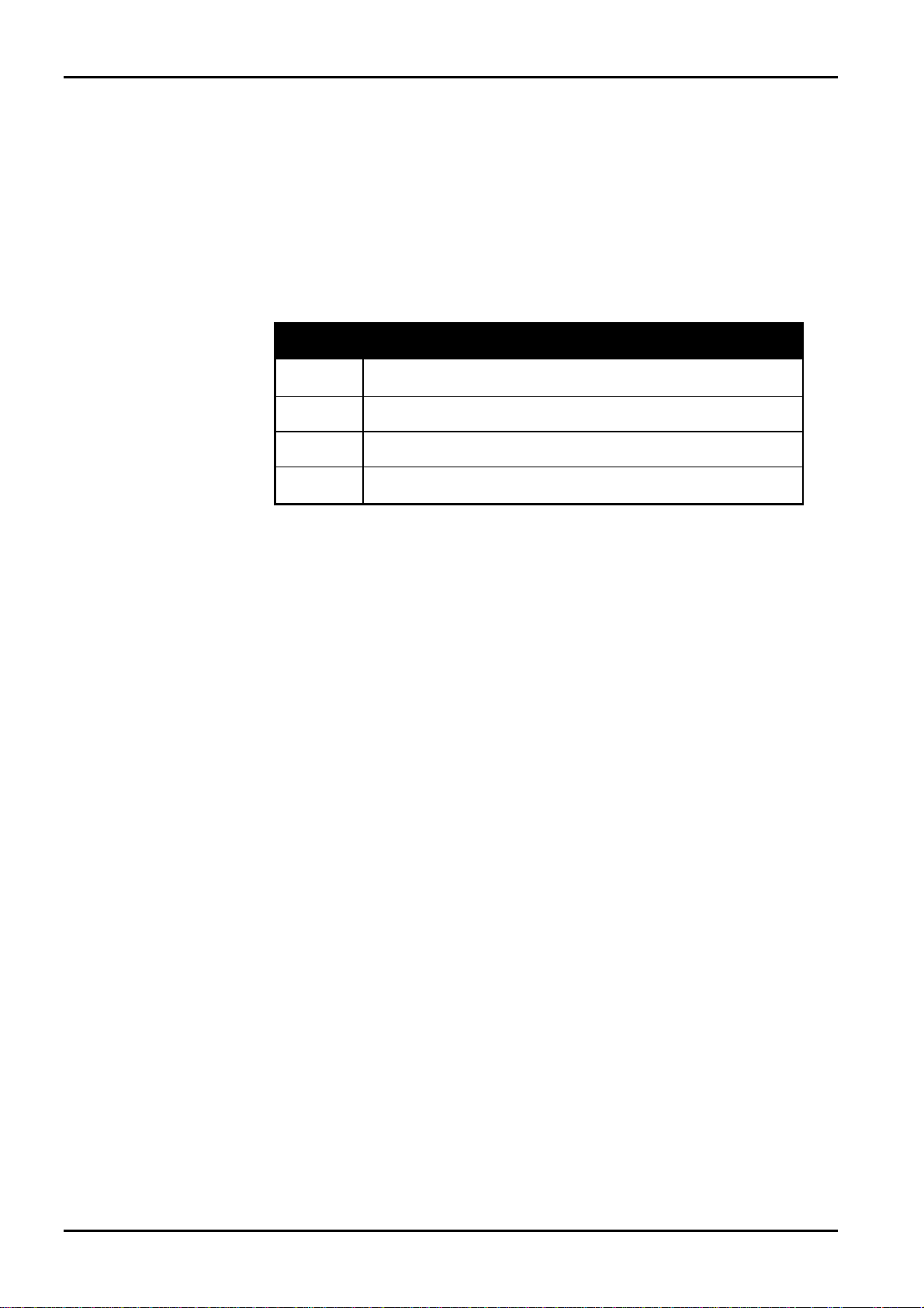
When programming these locations, you will notice that there are four alternatives per location.
You may select one, two, three or all of these alternatives for each location, however, only one
number is required to be programmed. This number is calculated by adding the option bit
numbers together.
Example
If at "LOCATION 177" you want options 1, 2 and 4, add the numbers together and the total is
the number to be programmed. In this example, the number to be programmed is 7 (i.e. 1 + 2
+ 4 = 7).
Option Description
1
Enabled = Allow Dialler Reporting Functions
Disabled = Disable All Dialler Reporting Functions
Solution 862
Installation Manual
2
4
8
Enable Remote Arming Via The Telephone
Enable Answering Machine Bypass Only When Armed
Enabled = Use Bell 103 For FSK Format
Disabled = CCITT V21 Format
Table 4: Example - Programming Option Bits
ISSUE130 Electronics Design and Manufacturing Pty Limited
Page 29

Programming 29
Installer’s Programming Commands
There are ten different commands that can be used to perform various functions once the
Installer's Programming Mode has been entered. To issue the command required, enter the
button.
corresponding numerical code followed by the
Command Description Page
#
958
959
960
961
962
963
964
965
966
999
Enable/Disable Zone Status Mode 30
Test Programming Key 31
Exit Installer’s Programming Mode 33
Reset Control Panel Back To Factory Default Settings 33
Copy The Control Panel Memory To The Programming
Key
Copy The Programming Key Data To The Control
Panel
Erase Programmin g Key 36
Set Up Domestic Dialling Format 37
Enable/Disable Automatic Stepping Of Locations
During Programming
This Command Displays The Control Panel’s Software
Version Number Or Control Panel Type
Table 5: Installer's Programming Commands
34
35
38
40
Electronics Design and Manufacturing Pty Limited ISSUE130
Page 30

30
Command 958 - Enable/Disable Zone Status Mode
This function enables and disables the zone status display mode when using the hand held
programmer. The hand held programmer will display the zones on the seven-segment display
from left to right. If there is a dash illuminated on the display of the hand held programmer,
the corresponding zone is unsealed and if the display is blank, the zone is sealed.
The third (or centre) display shows either the number 4 or the number 8. The number 4
constantly illuminated indicates that zones 1 - 4 are being displayed. The number 8 constantly
illuminated indicates that zones 5 - 8 are being displayed.
Solution 862
Installation Manual
Example
Pressing the
very useful during installation as the hand held p rogrammer allows you to view the status of
the zones directly at the control panel, saving you time and money.
button will toggle the display between the zones. This feature will prove to be
#
How To Enable Zone Status Mode
Enter Installers Programming Mode (i.e.
1.
Two beeps will be heard and the hand held programmer will display the data currently
programmed in “ LOCATION 000”.
Enter command
2.
Two beeps will be heard and the number 4 will illuminate to indicate zones 1 – 4 are
being displayed.
958
followed by the #button.
1234
followed by the #button).
How To Disable Zone Status Mode
Enter command
1.
Two beeps will be heard and you will return to the Installer’s Programming Mode.
A " - " in the display indicates the zone is unsealed.
A blank display indicates the zone is sealed.
958
followed by the #button.
À
À-4--
À
À
À8À-
-ÀÀÀ
À
ÀÀ
indicates that zone 1 is sealed and zones 2, 3 and 4 are unsealed.
indicates that zones 5 and 8 are unsealed and zones 6 and 7 are sealed.
ISSUE130 Electronics Design and Manufacturing Pty Limited
Page 31

Programming 31
Command 959 - Test Programming Key
This command initiates a test to be carried out on the programming key. Only the
Programming Key (CC891) may be used with the
The programming key test is non-destructive and any data in the programming key will remain
intact after the test has been completed. One long beep indicates that the programming key test
has failed and two beeps indicates a successful test.
If the programming key has been removed before the test is complete or the programming key
has failed, the data in the programming key has become corrupt. Remember not to remove the
programming key while the activity LED is constantly illuminated or pulsing rapidly.
How To Test The Programming Key
Solution 862
control panel.
Enter Installer's Programming Mode (i.e.
1.
Two beeps will be heard and the
remote codepad to indicate that you have entered Installer’s Programming Mode. You
will also notice that the remote codepad will display the data currently programmed in
“LOCATION 000”.
Plug the programming key onto the pins marked PROGRAMMING KEY on the control
2.
panel found at the top of the PCB (printed circuit board) next to the Auxiliary Module
socket.
Enter command
3.
Two beeps will be heard after the programming key has successfully been tested. If you
heard a long beep after issuing this command, the programming key has become corrupt
and will need to be erased to clear the corrupt data. Refer to Command 964 - Erase
Programming Key on page 36 for more information.
Before removing the programming key from the control panel, enter command
4.
960
beeps will be heard. The
codepad and the system will return to the disarmed state.
Failing to exit Installer’s Programming Mode before removing the programming key
may result in corrupting the data in the programming key.
959
followed by the #button to exit the Installer's Programming Mode. Two
followed by the #button.
STAY
STAY
and
1234
AWAY
and
AWAY
indicators will now extinguish on the remote
followed by the #button).
indicators will begin to flash on the
Electronics Design and Manufacturing Pty Limited ISSUE130
Page 32

32
How To Test The Programming Key Using The Hand Held Programmer
Before connecting the hand held programmer onto the pins marked PROGRAMMING
1.
KEY, make sure that the switch on the hand held programmer is in the EXT position
and that no external key has been plugged onto the hand held programmer.
Solution 862
Installation Manual
Enter the Installer's Programming Mode (i.e.
2.
Two beeps will be heard and the hand held programmer will display the data currently
programmed in “ LOCATION 000”.
Plug the programming key onto the pins marked EXTERNAL KEY on the hand held
3.
programmer.
Enter command
4.
Two beeps will be heard after the programming key has successfully been tested. If you
heard a long beep after issuing this command, the programming key has become corrupt
and will need to be erased to clear the corrupt data. Refer to Command 964 - Erase
Programming Key on page 36 for more information.
Before removing the programming key from the hand held programmer, enter command
5.
960
beeps will be heard and the system will now return to the disarmed state.
Failing to exit Installer’s Programming Mode before removing the programming key
may result in corrupting the data in the programming key.
959
followed by the #button to exit the Installer's Programming Mode. Two
followed by the #button.
1234
followed by the #button).
ISSUE130 Electronics Design and Manufacturing Pty Limited
Page 33

Programming 33
Command 960 - Exit Installer's Programming Mode
This command is used to exit the Installer's Programming Mode after you complete
programming the control panel.
You may exit Installer’s Programming Mode from any location by entering command
960
disarmed state. When using the remote codepad to program the system, you will notice that
the
Programming Mode.
followed by the #button. Two beeps will be heard and the system will return to the
STAY
and
AWAY
indicators will extinguish to indicate that you have terminated Installer’s
Command 961- Reset Control Panel Back To Factory Default
Settings
This command will reset the control panel back to the factory default values. Refer to the
default values shown throughout this manual or the programming sheets on pages 245 for more
information.
You may reset the control panel back to the factory default settings from any location when in
Installer’s Programming Mode. This is achieved by entering command
the
values.
button. Two beeps will be heard and the system will default back to the factory default
#
961
followed by
Electronics Design and Manufacturing Pty Limited ISSUE130
Page 34

34
Command 962 - Copy Control Panel Memory To Programming Key
This command is used to copy the control panel memory to the programming key. Only the
Programming Key (CC891) may be used with the
How To Copy The Control Panel Memory To The Programming Key
Solution 862
Solution 862
Installation Manual
control panel.
Enter Installer's Programming Mode (i.e.
1.
Two beeps will be heard and the
remote codepad to indicate that you have entered Installer’s Programming Mode. You
will also notice that the remote codepad will display the data currently programmed in
“LOCATION 000”.
Plug the programming key onto the pins marked PROGRAMMING KEY on the control
2.
panel found at the top of the PCB (printed circuit board) next to the Auxiliary Module
socket.
Enter command
3.
Two beeps will be heard after the control panel memory has successfully been copied
into the programming key. If you heard a long beep after issuing this command, the
programming key has become corrupt and will need to be erased to clear the corrupt
data. Refer to Command 964 - Erase Programming Key on page 36 for more
information.
Before removing the programming key from the control panel, enter command
4.
960
AWAY
and
system has returned to the disarmed state.
Failing to exit Installer’s Programming Mode before removing the programming key
may result in corrupting the programming key.
962
followed by the #button to exit Installer's Programming Mode. The
indicators will now extinguish on the remote codepad to indicate that the
followed by the #button.
STAY
1234
AWAY
and
followed by the #button).
indicators will begin to flash on the
STAY
How To Copy The Panel Memory To Programming Key Using The Hand Held Programmer
Before connecting the hand held programmer onto the pins marked PROGRAMMING
1.
KEY, make sure that the switch on the hand held programmer is in the EXT position
and that no external key has been plugged onto the hand held programmer.
Enter Installer's Programming Mode (i.e.
2.
Two beeps will be heard and the hand held programmer will display the data currently
programmed in “ LOCATION 000”.
Plug the programming key onto the pins marked EXTERNAL KEY on the hand held
3.
programmer.
Enter command
4.
Two beeps will be heard after the control panel memory has successfully been copied
into the programming key. If you heard a long beep after issuing this command, the
programming key has become corrupt and will need to be erased to clear the corrupt
data. Refer to Command 964 - Erase Programming Key on page 36 for more
information.
Before removing the programming key from the hand held programmer, enter command
5.
960
will be heard and the system will now return to the disarmed state.
Failing to exit Installer’s Programming Mode before removing the programming key
may result in corrupting the programming key.
962
followed by the #button to exit Installer's Programming Mode. Two beeps
followed by the #button.
1234
followed by the #button).
ISSUE130 Electronics Design and Manufacturing Pty Limited
Page 35

Programming 35
Command 963 - Copy From Programming Key To Control Panel
This command is used to copy data from the programming key to the control panel. Only the
Programming Key (CC891) may be used with the
How To Copy The Programming Key Memory To The Control Panel
Solution 862
control panel.
Enter Installer's Programming Mode (i.e.
1.
Two beeps will be heard and the
remote codepad to indicate that you have entered Installer’s Programming Mode. You
will also notice that the remote codepad will display the data currently programmed in
“LOCATION 000”.
Connect the programming key onto the pins marked PROGRAMMING KEY on the
2.
control panel found at the top of the PCB (printed circuit board) next to the Auxiliary
Module socket.
Enter command
3.
Two beeps will be heard after the programming key's data has successfully been copied
into to the control panel. If you heard a long beep after issuing this command, the
programming key has become corrupt and will need to be erased to clear the corrupt
data. Refer to Command 964 - Erase Programming Key on page 36 for more
information.
Before removing the programming key from the control panel, enter command
4.
960
AWAY
and
return to the disarmed state.
Failing to exit Installer’s Programming Mode before removing the programming key
may result in corrupting the programming key.
963
followed by the #button to exit Installer's Programming Mode. The
indicators will now extinguish on the remote codepad and the system will
followed by the #button.
STAY
1234
AWAY
and
followed by the #button).
indicators will begin to flash on the
STAY
How To Copy Programming Key Memory To Control Panel Using Hand Held Programmer
Before connecting the hand held programmer onto the pins marked PROGRAMMING
1.
KEY, make sure that the switch on the hand held programmer is in the EXT position
and that no external key has been plugged onto the hand held programmer.
Enter Installer's Programming Mode (i.e.
2.
Two beeps will be heard and the hand held programmer will display the data currently
programmed in “ LOCATION 000”.
Plug the programming key onto the pins marked EXTERNAL KEY on the hand held
3.
programmer.
Enter command
4.
Two beeps will be heard after the programming key's data has successfully been copied
into to the control panel. If you heard a long beep after issuing this command, the
programming key has become corrupt and will need to be erased to clear the corrupt
data. Refer to Command 964 - Erase Programming Key on page 36 for more
information.
Before removing the programming key from the hand held programmer, enter command
5.
960
will be heard and the system will now return to the disarmed state.
Failing to exit Installer’s Programming Mode before removing the programming key
may result in corrupting the programming key.
963
followed by the #button to exit Installer's Programming Mode. Two beeps
followed by the #button.
1234
followed by the #button).
Electronics Design and Manufacturing Pty Limited ISSUE130
Page 36

36
Command 964 - Erase Programming Key
This command erases all data from the programming key. Only the Programming Key
(CC891) may be used with the
How To Erase The Programming Key
Solution 862
Solution 862
control panel.
Installation Manual
Enter Installer's Programming Mode (i.e.
1.
Two beeps will be heard and the
remote codepad to indicate that you have entered Installer’s Programming Mode. You
will also notice that the remote codepad will display the data currently programmed in
“LOCATION 000”.
Connect the programming key onto the pins marked PROGRAMMING KEY on the
2.
control panel found at the top of the PCB (printed circuit board) next to the Auxiliary
Module socket.
Enter command
3.
Two beeps will be heard after the programming keys data has been deleted.
Before removing the programming key from the control panel, enter command
4.
960
AWAY
and
return to the disarmed state.
Failing to exit Installer’s Programming Mode before removing the programming key
may result in corrupting the programming key.
964
followed by the #button to exit Installer's Programming Mode. The
indicators will now extinguish on the remote codepad and the system will
followed by the #button.
STAY
1234
AWAY
and
followed by the #button).
indicators will begin to flash on the
How To Erase The Programming Key Using The Hand Held Programmer
Before connecting the hand held programmer onto the pins marked PROGRAMMING
1.
KEY, make sure that the switch on the hand held programmer is in the EXT position
and that no external key has been plugged onto the hand held programmer.
STAY
Enter Installer's Programming Mode (i.e.
2.
Two beeps will be heard and the hand held programmer will display the data currently
programmed in “ LOCATION 000”.
Plug the programming key onto the pins marked EXTERNAL KEY on the hand held
3.
programmer.
Enter command
4.
Two beeps will be heard after the programming keys data has been deleted.
Before removing the programming key from the hand held programmer, enter command
5.
960
will be heard and the system will now return to the disarmed state.
Failing to exit Installer’s Programming Mode before removing the programming key
may result in corrupting the programming key.
964
followed by the #button to exit Installer's Programming Mode. Two beeps
followed by the #button.
1234
followed by the #button).
ISSUE130 Electronics Design and Manufacturing Pty Limited
Page 37

Programming 37
Command 965 - Set Up Domestic Dialling Format
Command 965 has been included to allow the set up of the domestic dialling format a one step
operation. Refer to page 120 for more information on Domestic Dialling Format.
After you enter Installer's Programming Mode, enter command
button. The command will automatically set Receiver 1 to domestic reporting and set the
following locations only for Receiver 2. No other locations will be changed when command
965 has been issued.
All domestic telephone numbers are stored in “LOCATION 466 – 513”. For more information
on programming domestic dialling, refer to Setting Up and Programming Domestic Reporting
on page 121 for more information.
Location Description Setting
LOCATION 032 Handshake Tone For Receiver 1
LOCATION 033 Transmission Format
LOCATION 034 – 039 Subscriber ID Number 0, 0, 0, 0, 0,
LOCATION 332 Zone Status Reporting Options
LOCATION 333 – 334 Open/Close Reports
LOCATION 335 Open/Close Reporting Options
LOCATION 356 - 358 System Status – Access Denied
LOCATION 359 System Status Reporting Options
LOCATION 360 - 366 Test Reporting Time 0, 0, 0, 0,
LOCATION 367 Test Reporting Dialler Options
1
4
2
11, 12
2
6, 7, 12
2
7, 1, 0
1
965
1
followed by the
(Handshake Tone)
(Domestic)
(1 Beep)
(Receiver 2 Only)
(Open/Close Reports)
(Receiver 2 Only)
(Access Denied)
(Receiver 2 Only)
(Test Reports)
(Receiver 1 Only)
#
Table 6: Command 965 Defaults
As you can see from the table above, the transmission format has automatically been set for
domestic dialling and the Subscriber ID Number has been set for one identification beep. All
reports except zone status reporting and system status reporting have been allocated to
Receiver 1 for domestic dialling.
This means that the zone status reports including zone bypass, zone trouble, sensor watch and
alarm restore codes as well as system status reports including fuse fail, AC fail, low battery and
access denied reports have b een allocated to Receiver 2 and will not report unless Receiver 2
has also been set up to report.
Electronics Design and Manufacturing Pty Limited ISSUE130
Page 38

38
Solution 862
Command 966 - Enable/Disable Automatic Stepping Of Locations
This command allows automatic stepping of locations while programming via Installer’s
Programming Mode. When enabled via the hand held programmer, the decimal point of the
left most display will reflect the mode of operation.
If the decimal point is illuminated on the hand held programmer, automatic stepping of
locations is active. n automatic increment of the location being programmed will occur as
soon as the
If the decimal point is not illuminated on the hand held programmer, the automatic stepping of
locations is disabled and programming the next location will need to be manually selected by
pressing the
useful when programming successive lo cations.
When programming via the remote codepad, there are no visual indications to display if
automatic stepping of locations has been enabled.
*
#
How To Enable Automatic Stepping Of Locations
A
button is pressed positioning you at the next location ready for programming.
button. As you can see from the examples below, auto step mode can be very
Installation Manual
Enter Installer’s Programming Mode (i.e.
1.
Two beeps will be heard.
If you are using the remote codepad, the
to indicate that you have entered Installer’s Programming Mode. You will also notice
that the remote codepad will display the data currently programmed in “LOCATION
000”.
Enter command
2.
Two beeps will be heard.
966
followed by the # button.
1234
STAY
followed by the # button).
AWAY
and
indicators will begin to flash
How To Disable Automatic Stepping Of Locations
Enter command
1.
Two beeps will be heard.
966
followed by the # button.
Example
(Auto Step Enabled)
To enter the Primary Telephone Number "02 pause 9672 1055" with auto step enabled (i.e.
Decimal point illuminated when using the hand held programmer).
followed by the # button.
0
Press
(This will position you at "LOCATION 000" being the start of the Primary Telephone Number
For Receiver 1).
+ * + 2 + * + + * + 9 + * + 6 + * + 7 +
+
2 + * + 1 + * + + * + 5 + * + 5 + * + 0 +
*
ISSUE130 Electronics Design and Manufacturing Pty Limited
*
Page 39

Programming 39
Example
(Auto Step Disabled)
To enter the Primary Telephone Number "02 pause 9672 1055" with auto step disabled (i.e.
Decimal point e xt inguished when using the hand held programmer).
Press
(This will position you at "LOCATION 000" being the start of the Primary Telephone Number
For Receiver 1).
+
+
followed by the # button.
0
+ * + # + 2 + * + # + + * + # + 9 + * + #
6 + * + # + 7 + * + # + 2 + * + # + 1 + * + #
+ * + # + 5 + * + # + 5 + * + # + 0 + *
Electronics Design and Manufacturing Pty Limited ISSUE130
Page 40

40
Command 999 - Display Panel Type Or Software Version Number
When using this command via the remote codepad, the codepad will display the panel version
of the control panel. As there are two different control panel’s using the same PCB, it is
difficult to know which control panel the PCB has been set up to be.
The codepad will display a 6 indicating the software of the control panel. Refer to the “Table
7: Control Panel Type” below for more information.
When using this command via the hand held programmer, the hand held programmer will
display the software version number of the control panel.
How To Display The Control Panel Type Or Software Version Number
Solution 862
Indicator Control Panel Type
6
Table 7: Control Panel Type
Solution 862
Installation Manual
Enter Installer’s Programming Mode (i.e.
1.
Two beeps will be heard and the data currently programmed in “LOCATION 000” will
be displayed via the hand held programmer or remote codepad.
If you are using the remote codepad, the
to indicate that you have entered Installer’s Programming Mode.
Enter command
2.
Two beeps will be heard.
If you are using the hand held programmer, the right display will indicate the software
version number of the control panel.
If you are using the remote codepad, the codepad will display a zone indicator
corresponding to the control panel type. Refer to “Table 7: Control Panel Type” above
for more information.
Press the
3.
Mode.
Enter command
4.
Mode. Two beeps will be heard and the system will now return to the disarmed state.
If you are using the remote codepad, the
indicate that you have returned to the disarmed state.
999
button to exit this command and return to the Installer’s Programming
#
960
followed by the #button.
followed by the #button to exit Installer's Programming
1234
STAY
STAY
followed by the #button).
AWAY
and
and
indicators will begin to flash
AWAY
indicators will extinguish to
ISSUE130 Electronics Design and Manufacturing Pty Limited
Page 41

Programming 41
Disable Factory Default
LOCATION 900
0
This feature prevents the control panel from being manually defaulted via the default button or
to prevent using a programming key to perform an automatic download to the control panel
when the system is disarmed.
A zero programmed into this location will allow defaulting of the control panel. If 15 has been
programmed into this location, defaulting of the control panel will not be permitted and the
Installer Code MUST be used for further programming of the control panel.
If the Installer Code is not known, the control panel will need to be returned to your EDM
Distributor for exchange. A nominal fee applies for this service.
Electronics Design and Manufacturing Pty Limited does not recommend the use of this
feature.
If the option is required to disable the option of being able to default the control panel, a
special procedure has been implemented to eliminate the possibility of accidentally setting this
option. The default button on the PCB must be held down while programming this location.
How To Prevent Manual Defaulting Of The Control Panel
Enter Installer’s Programming Mode (i.e.
1.
Two beeps will be heard and the data currently programmed in “LOCATION 000” will
be displayed via the hand held programmer or remote codepad.
If you are using a remote codepad, the
indicate that Installer’s Programming Mode has been accessed.
From the hand held programmer or remote codepad, go to "LOCATION 900".
2.
(e.g.. 900
Hold down and continue to hold down the DEFAULT button.
3.
The default button will be located at the top of the PCB next to the PROGRAMMING
KEY connecting socket.
Program a 15 into "LOCATION 900".
4.
15
(e.g..
Release the default button.
5.
Enter command
6.
Mode. Two beeps will be heard and the system will return to the disarmed state.
If you are using a remote codepad, the
indicate that the system has returned to the disarmed state.
followed by the #button).
followed by the *button).
960
followed by the #button to exit Installer's Programming
1234
STAY
and
STAY
and
followed by the #button).
AWAY
indicators will begin to flash to
AWAY
indicators will extinguish to
Electronics Design and Manufacturing Pty Limited ISSUE130
Page 42

42
Defaulting The Control Panel
Solution 862
If the
follow the procedure outlined below to successfully default the control panel back to the
factory default settings.
How To Default The Control Panel Via Installer Code
Enter Installer Programming Mode.
1.
1234
(e.g..
AWAY
and
programming mode.
indicators will begin to flash to indicate that you have accessed
Solution 862
control panel does not have "LOCATION 900" programmed as 15,
followed by the #button). Two beeps will be heard. T he
Installation Manual
STAY
Enter Installer’s Programming Command
2.
Two beeps will be heard after the control panel has successfully been defaulted.
Enter Installer’s Programming Command 960 followed by the # button.
3.
Two beeps will be heard. The
system will return to the disarmed state.
The control panel has now been successfully defaulted back to the factory default
settings.
STAY
965
and
AWAY
followed by the #button.
indicators will cease to flash and the
How To Default The Control Panel Via Default Button
Disconnect the AC mains supply and the backup battery from the control panel.
1.
Hold down and continue to hold down the DEFAULT button.
2.
The default button is located at the top of the PCB next to the PROGRAMMING KEY
connecting socket.
Reconnect the AC mains supply to the control panel.
3.
After reconnecting the AC mains supply, wait for 3-5 seconds before releasing the
4.
DEFAULT button.
Disarm the system using the default Master Code (e.g.. Enter
5.
the
button).
#
2580
followed by
The control panel has now been successfully defaulted back to the factory default
settings.
If you hear the dialler seize relay (RL2) click four times while attempting to default the
control panel, this would indicate that the feature of defaulting the control panel has
been disabled in “LOCATION 900” on page 41. The control panel will need to be returned
to Electronics Design and Manufacturing Pty Limited for exchange where a service fee
will be charged to unlock the control panel's memory if the Installer Code is not known.
ISSUE130 Electronics Design and Manufacturing Pty Limited
Page 43

This section includes the following;
•
CP5 Eight Zone LED Codepad
•
CP5 Eight Zone LCD Codepad
Codepad Indicators
Page 44

44
CP5 Eight Zone LED Codepad
The codepad is the communications interface between you and your alarm
system. The codepad allows you to issue commands and offers both visual
and audible indications that guide you through the general operation.
Solution 862
Installation Manual
Figure 1: CP5 Eight Zone Codepad (CP508)
Zone Indicators
ZONE
The
various circumstances that the indicators will display (i.e. Zone Sealed, Zone Unsealed).
(0.25 Sec On – 0.25 Sec Off)
indicators are used to display the status of the zones. The following table lists the
Indicator Definition
Flashing Fast
Flashing Slow
(1 Sec On – 1 Sec Off)
The codepad incorporates numerous indicators. T here are
that are used to show the condition of each zone and four others for general
status. The following is a list of situations and the relevant indications that
will be seen.
On
Off
Zone Is Unsealed
Zone Is Sealed
Zone Is In Alarm Condition
Zone Is Manually Isolated
Table 8: Zone Indicators
ZONE
indicators
AWAY Indicator
AWAY
The
indicator will also flash in unison with the
or Master Code Functions are used.
Refer to page 52 for more information on the different methods on arming the system in
AWAY Mode.
indicator is used to display that the system is armed in
STAY
indicator when Installer’s Programming Mode
Indicator Definition
On
Off
System Is Armed In AWAY Mode
System Is Not Armed In AWAY Mode
Table 9: AWAY Indicator
AWAY
Mode. The
AWAY
ISSUE130 Electronics Design and Manufacturing Pty Limited
Page 45
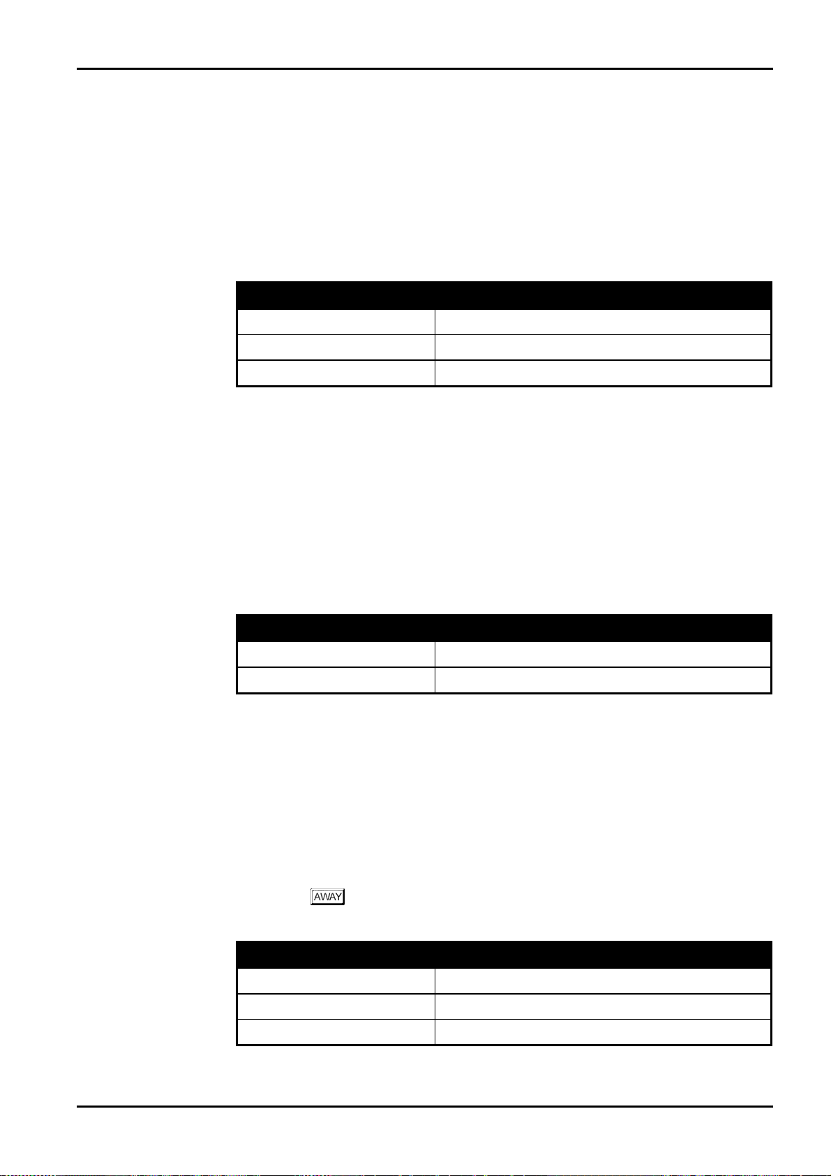
Codepad Indicators 45
STAY Indicator
STAY
The
Mode 2. The
Installer’s Programming Mode or Master Code Functions are used.
Refer to page 54 for the different methods of arming the system in STAY Mode 1. Refer to
Zone Options 1 on page 167 for information on setting zones to be automatically isolated in
STAY Mode 1. For the method of arming the system in STAY Mode 2, refer to page 57.
Refer to Setting STAY Mode 2 Zones on page 85 when using the Installer Code or Setting
STAY Mode 2 Zones on page 101 when using the Master Code.
indicator is used to display that the system is armed in STAY Mode 1 or STAY
STAY
indicator will also flash in unison with the
Indicator Definition
AWAY
indicator when
On
Off
Flashing
System Is Armed In STAY Mode 1 Or STAY Mode 2
System Is Not Armed In STAY Mode
Zone Isolating Mode Or Setting STAY Mode 2 Zones
Table 10: STAY Indicator
MAINS Indicator
MAINS
The
failed.
When programming numbers (i.e. Installer’s Programming Mode or Master Code Functions),
MAINS
the
MAINS
you program a twelve, the
indicator is used to display that the systems AC mains supply is normal or has
indicator will illuminate when you program numbers between 10 and 15. The
indicator represents digit 10 plus the value of the illuminated zone indicator (e.g.: If
MAINS
indicator and zone 2 will illuminate).
Indicator Definition
On
Flashing
AC Mains Power Normal
AC Mains Failure
Table 11: MAINS Indicator
FAULT Indicator
FAULT
The
Fault Analysis Mode on page 63 for more information on system faults.
Every time a new system fault has been detected (e.g.:
will begin to beep once every minute.
Pressing the button once will cancel the once a minute beep and acknowledge the fault
(e.g.:
indicator is used to display that the system has detected a system fault. Refer to
FAULT
indicator flashing), the codepad
FAULT
indicator on).
Indicator Definition
On
Off
Flashing
Electronics Design and Manufacturing Pty Limited ISSUE130
There Is A System Fault That Needs To Be Rectified
The System Is Normal, There Are No Faults
There Is A System Fault Waiting To Be Acknowledged
Table 12: FAULT Indicator
Page 46

46
Audible Indicators
In general, the audible indications given out by the codepad are as follows:
Indicator Definition
One Short Beep
Solution 862
A Button Has Been Pressed On The Codepad Or End
Of Exit Time When Armed In Either STAY Mode 1 Or
STAY Mode 2
Installation Manual
Two Short Beeps
Three Short Beeps
One Long Beep
One Short Beep Every Second
One Short Beep Every Two
Seconds
One Short Beep Every Minute
The System Has Accepted Your Code
The Requested Function Has Been Executed
Indicates The End Of Exit Time In AWAY Mode Or
The Requested Operation Has Been Denied Or Aborted
Walk Test Mode Is Currently Active Or Warning
Before Automatic Arming Takes Place
Telephone Monitor Mode Is Active
There Is A System Fault Waiting To Be Acknowledged
Table 13: Audible Indications
ISSUE130 Electronics Design and Manufacturing Pty Limited
Page 47
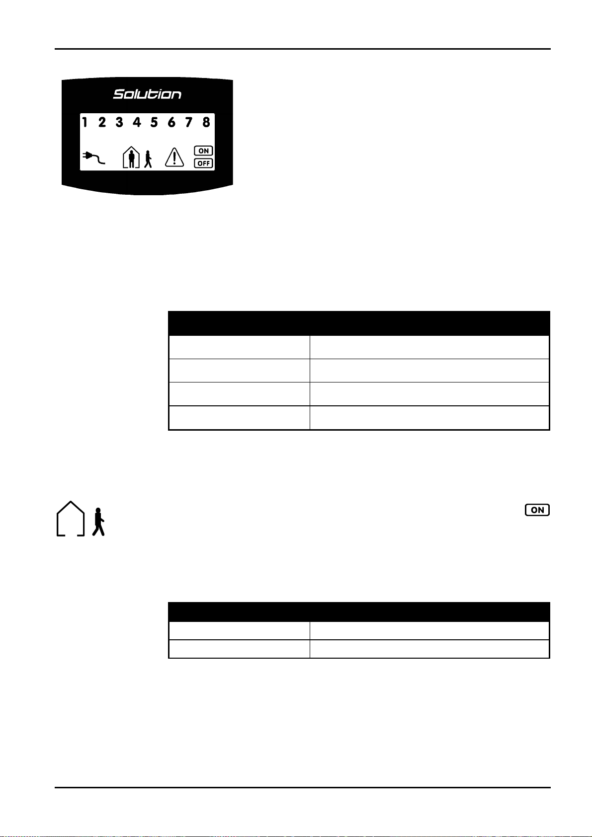
Codepad Indicators 47
CP5 Eight Zone LCD Codepad
The codepad is the communications interface between you and your alarm
system. The codepad allows you to issue commands and offers both visual
and audible indications that guide you through the general operation.
Figure 2: CP5 Eight Zone LCD Codepad
(CP508L)
Zone Indicators
ZONE
The
1 2 3 ....
various circumstances that the indicators will display (i.e. Zone Sealed, Zone Unsealed).
(0.25 Sec On – 0.25 Sec Off)
The codepad incorporates numerous indicators. T here are
that are used to show the condition of each zone and seven others for general
status. The following is a list of situations and the relevant indications that
will be seen.
indicators are used to display the status of the zones. The following table lists the
Indicator Definition
On
Off
Flashing Fast
Flashing Slow
(1 Sec On – 1 Sec Off)
Zone Is Unsealed
Zone Is Sealed
Zone Is In Alarm Condition
Zone Is Manually Isolated
ZONE
indicators
Table 14: Zone Indicators
AWAY Indicator
AWAY
The
indicator will also illuminate when the system is armed in AWAY Mode. The
will also flash in unison with the
Master Code Functions are used.
Refer to page 52 for more information on the different methods on arming the system in
AWAY Mode.
indicator is used to display that the system is armed in
STAY
indicator when Installer’s Programming Mode or
Indicator Definition
On
Off
System Is Armed In AWAY Mode
System Is Not Armed In AWAY Mode
Table 15: AWAY Indicator
AWAY
Mode. The
AWAY
indicator
Electronics Design and Manufacturing Pty Limited ISSUE130
Page 48

48
STAY Indicator
STAY
The
Mode 2. The
Installer’s Programming Mode or Master Code Functions are used.
indicator is used to d isplay that the system is armed in STAY Mode 1 or STAY
STAY
Solution 862
indicator will also flash in unison with the
Installation Manual
AWAY
indicator when
The
Mode 2.
Refer to page 54 for the different methods of arming the system in STAY Mode 1. Refer to
Zone Options 1 on page 167 for information on setting zones to be automatically isolated in
STAY Mode 1. For the method of arming the system in STAY Mode 2, refer to page 57.
Refer to Setting STAY Mode 2 Zones on page 85 when using the Installer Code or Setting
STAY Mode 2 Zones on page 101 when using the Master Cod to program zones to be
automatically isolated in STAY Mode 2.
indicator will also illuminate when the system is armed in STAY Mode 1 or STAY
Indicator Definition
On
Off
Flashing
System Is Armed In STAY Mode 1 Or STAY Mode 2
System Is Not Armed In STAY Mode
Zone Isolating Mode Or Setting STAY Mode 2 Zones
Table 16: STAY Indicator
System Disarmed
This indicator will illuminate with the indicator when the system has been disarmed.
Flashing
MAINS Indicator
MAINS
The
failed.
When programming numbers (i.e. Installer’s Programming Mode or Master Code Functions),
MAINS
the
MAINS
you program a twelve, the
indicator is used to display that the systems AC mains supply is normal or has
indicator will illuminate when you program numbers between 10 and 15. The
indicator represents digit 10 plus the value of the illuminated zone indicator (e.g.: If
MAINS
indicator and zone 2 will illuminate).
Indicator Definition
On
Flashing
AC Mains Power Normal
AC Mains Failure
Table 17: MAINS Indicator
Zone Isolating Mode
This indicator will flash once every 3 seconds when you attempt to isolate zones or program
zones to be automatically isolated for STAY Mode 2. The person will flash once every 3
seconds.
Refer to Isolating Zones on page 60 for information on how to manually isolate zones. Refer to
Setting STAY Mode 2 Zones on page 85 when using the Installer Code or Setting STAY Mode
2 Zones on page 101 when using the Master Cod to program zones to be automatically isolated
in STAY Mode 2.
ISSUE130 Electronics Design and Manufacturing Pty Limited
Page 49

Codepad Indicators 49
FAULT Indicator
FAULT
The
Fault Analysis Mode on page 63 for more information on system faults.
indicator is used to display that the system has detected a system fault. Refer to
Flashing
Every time a new system fault has been detected (e.g.:
will begin to beep once every minute.
Pressing the
FAULT
(e.g.:
button once will cancel the once a minute beep and acknowledge the fault
indicator on).
Indicator Definition
On
Off
Flashing
There Is A System Fault That Needs To Be Rectified
The System Is Normal, There Are No Faults
There Is A System Fault Waiting To Be Acknowledged
Table 18: FAULT Indicator
FAULT
indicator flashing), the codepad
Programming Mode
These two indicators will flash when the system has entered either Installer’s Programming
Mode or when any Master Code Functions are used.
Off Indicator/Zone Sealed
The indicator will illuminate when the system is in the disarmed state or Installer’s
Programming Mode has been entered and will flash when a zone becomes unsealed during the
disarmed state. T he indicator will stop flashing when all zones are sealed.
On Indicator/Zone In Alarm
The indicator will illuminate when the system is armed in
when an alarm occurs. The indicator will reset once a valid user code has been entered.
AWAY
Mode and will flash
Electronics Design and Manufacturing Pty Limited ISSUE130
Page 50

50
Audible Indicators
In general, the audible indications given out by the codepad are as follows:
Indicator Definition
One Short Beep
Solution 862
A Button Has Been Pressed On The Codepad Or End
Of Exit Time When Armed In Either STAY Mode 1 Or
STAY Mode 2
Installation Manual
Two Short Beeps
Three Short Beeps
One Long Beep
One Short Beep Every Second
One Short Beep Every Two
Seconds
One Short Beep Every Minute
The System Has Accepted Your Code
The Requested Function Has Been Executed
Indicates The End Of Exit Time In AWAY Mode Or
The Requested Operation Has Been Denied Or Aborted
Walk Test Mode Is Currently Active Or Warning
Before Automatic Arming Takes Place
Telephone Monitor Mode Is Active
There Is A System Fault Waiting To Be Acknowledged
Table 19: Audible Indications
ISSUE130 Electronics Design and Manufacturing Pty Limited
Page 51

This section includes the following;
•
Arming The System In AWAY Mode
•
Disarming The System From AWAY Mode
•
Arming The System In STAY Mode 1
•
Disarming The System From STAY Mode 1
•
Arming The System In STAY Mode 2
•
Disarming The System From STAY Mode 2
•
Codepad Duress Alarm
•
Codepad Panic Alarm
•
Codepad Fire Alarm
System Operations
•
Codepad Medical Alarm
•
Isolating Zones
•
Fault Analysis Mode
Page 52

52
System Operations
This section explains the general operations of the system. The operations will explain how to
arm and disarm the system in the various modes, how to isolate zones, initiate codepad alarms
and determine any fault that may occur.
Arming The System In AWAY Mode
Arming the system in AWAY Mode is normally performed when you leave the premises and
require that all zones be activated in a ready state to detect any intrusion.
There are two different methods for arming the system in AWAY Mode. Method one is
standard and will always operate. Method two is optional and needs Option 2 in "LOCATION
429" to be enabled on page 220.
If you require to isolate a zone(s) prior to arming the system in AWAY Mode, refer to Isolating
Zones on page 60.
Single button arming in AWAY Mode will report as user code number 16.
Solution 862
Installation Manual
Method One
Method Two
How To Arm The System In AWAY Mode
Enter your
1.
Two beeps will be heard and the
commence.
followed by the button.
AWAY
indicator will illuminate. Exit time will now
+
How To Arm The System In AWAY Mode
Hold down the
1.
AWAY
The
2 in "LOCATION 429" on page 220 to enable single button arming in AWAY Mode.
If a zone is not sealed at the end of exit time, the zone will be automatically isolated and will
be constantly illuminated on the remote codepad. The zone will become an active part of the
system again as soon as it has resealed (i.e. If a window is left open after exit time has expired,
the window will not be an active part of the system until it has closed. Opening the window
after exit time has expired will cause an alarm condition).
indicator will illuminate and exit time will now commence. Refer to Option
button until two beeps are heard.
Forced Arming
The feature of arming the system when a zone is not sealed is known as forced arming. Refer
to Zone Options 2 on page 171 to enable forced arming for each zone.
AWAY
If the
system in AWAY Mode, forced arming is not permitted. If this is the case, you must ensure
that all zones are sealed or manually isolated before you can arm the system.
ISSUE130 Electronics Design and Manufacturing Pty Limited
indicator does not illuminate and a long beep is heard when attempting to arm the
Page 53

System Operations 53
Disarming The System From AWAY Mode
When you enter the premises after the system has been armed in AWAY Mode, you will need
to disarm the system from AWAY Mode to disable detection devices that will activate the
sirens, strobe and bell outputs.
If there has been an alarm condition prior to disarming the system from AWAY Mode, a
flashing
How To Disarm The System From AWAY Mode
ZONE
indicator will be displayed, indicating a previous alarm on that zone.
Enter your
1.
Two beeps will be heard and the
followed by the button.
AWAY
indicator will extinguish.
+
Electronics Design and Manufacturing Pty Limited ISSUE130
Page 54

54
Arming The System In STAY Mode 1
Arming the system in STAY Mode 1 is only used when the perimeter and unused areas of the
premises need to be armed to detect any would be intruder from entering the premises, at the
same time allowing you to move freely within an area which has been automatically isolated.
Programming zones to be automatically isolated in STAY Mode 1 can only be programmed by
the installer. Refer to Zone Options 2 on page 171 for further information on setting zones to
be automatically isolated in STAY Mode 1.
There are two methods for arming your system in STAY Mode 1. Method one is standard and
will always operate. Method two is optional and needs Option 2 in "LOCATION 429" to be
enabled on page 220.
Entry Guard Timer For STAY Mode
When arming the system in STAY Mode 1, an optional entry timer called Entry Guard Timer
For STAY Mode may be used to delay the sirens, strobe and bell outputs if a zone that has not
been automatically isolated has triggered into alarm condition. Entry Guard Timer For STAY
Mode is the delay time used for all zones except 24 hour zones when the system is armed in
STAY Mode 1 or STAY Mode 2.
If the Entry Guard Timer For STAY Mode has been programmed and a zone that has not been
automatically isolated has triggered, the codepad will beep twice a second until the Entry
Guard Timer For STAY Mode has expired or the system has been disarmed. If the alarm
condition has not been reset before Entry Guard Timer For STAY Mode expires, the strobe,
bell and siren outputs will activate into alarm.
Solution 862
Installation Manual
Method One
Single button arming in STAY Mode 1 will report as user code number 16.
How To Arm The System In STAY Mode 1
Enter your
1.
Two beeps will be heard and the
commence.
Any zones that have been programmed to be automatically isolated in STAY Mode 1
will begin to flash until exit time expires. At the end of exit time, the
will extinguish and the codepad will give one short beep.
followed by the button.
STAY
indicator will illuminate. Exit time will now
ZONE
+
indicators
ISSUE130 Electronics Design and Manufacturing Pty Limited
Page 55

System Operations 55
Method Two
How To Arm The System In STAY Mode 1
Hold down the
1.
STAY
The
Any zones that have been programmed to be automatically isolated in STAY Mode 1
will begin to flash until exit time expires. At the end of exit time, the
will extinguish and the codepad will give one short beep.
If a zone is not sealed at the end of exit time, the zone will be automatically isolated and will
be constantly illuminated on the remote codepad. The zone will become an active part of the
system again as soon as it has resealed (i.e. If a window is left open after exit time has expired,
the window will not be an active part of the system until it has closed. Opening the window
after exit time has expired will cause an alarm condition).
indicator will illuminate and exit time will now commence.
button until two beeps are heard.
ZONE
indicators
Forced Arming
The feature of arming the system when a zone is not sealed is known as forced arming. Refer
to Zone Options 2 on page 171 to enable forced arming for each zone.
STAY
If the
system in STAY Mode 1, forced arming is not permitted. If this is the case, you must ensure
that all zones are sealed or manually isolated before you can arm the system.
indicator does not illuminate and a long beep is heard when attempting to arm the
Electronics Design and Manufacturing Pty Limited ISSUE130
Page 56

56
Disarming The System From STAY Mode 1
There are two methods for disarming the system from STAY Mode 1. Method one is standard
and will always operate. Method two is optional and needs Option 4 to be enabled in
"LOCATION 429" on page 220.
Method two will not operate unless both Option 2 and Option 4 has been enabled in
"LOCATION 429" on page 220.
Method One
How To Disarm The System From STAY Mode 1
Solution 862
Installation Manual
Method Two
Enter your
1.
Two beeps will be heard and the
disarmed.
followed by the button.
STAY
indicator will extinguish. The system is now
+
A flashing
user code will need to be used to disarm the system using method one. To enable method two,
Option 4 in "LOCATION 429" on page 220 will need to be enabled.
How To Disarm The System From STAY Mode 1
1.
ZONE
indicator represents a previous alarm on that zone. If this is the case, a valid
Hold down the
STAY
The
indicator will extinguish and the system is now disarmed.
button until two beeps are heard.
Single button disarming from STAY Mode 1 will report as user code number 16.
ISSUE130 Electronics Design and Manufacturing Pty Limited
Page 57

System Operations 57
Arming The System In STAY Mode 2
Arming the system in STAY Mode 2 is only used when the perimeter and unused areas of the
premises need to be armed to detect any would be intruder from entering the premises, at the
same time allowing you to move freely within an area which has been automatically isolated.
Programming zones to be automatically isolated in STAY Mode 2 can be programmed either
by the Installer Code Function – Setting STAY Mode 2 Zones on page 85 or Master Code
Functions - Setting STAY Mode 2 Zones on page 101.
Entry Guard Timer For STAY Mode
When arming the system in STAY Mode 2, an optional entry timer called Entry Guard Timer
For STAY Mode may be used to delay the sirens, strobe and bell outputs if a zone that has not
been automatically isolated has triggered into alarm condition. Entry Guard Timer For STAY
Mode is the delay time used for all zones except 24 hour zones when the system is armed in
STAY Mode 1 or STAY Mode 2.
If the Entry Guard Timer For STAY Mode has been programmed and a zone that has not been
automatically isolated has triggered, the codepad will beep twice a second until the Entry
Guard Timer For STAY Mode has expired or the system has been disarmed. If the alarm
condition has not been reset before Entry Guard Timer For STAY Mode expires, the strobe,
bell and siren outputs will activate into alarm.
Single button arming in STAY Mode 2 will report as user code number 16.
How To Arm The System In STAY Mode 2
button until two beeps are heard.
Hold down the
1.
STAY
The
Any zones that have been programmed to be automatically isolated in STAY Mode 2
will begin to flash until exit time expires. At the end of exit time, the
will extinguish and the codepad will give one short beep.
0
indicator will illuminate and exit time will now commence.
ZONE
indicators
0
If a zone is not sealed at the end of exit time, the zone will be automatically isolated and will
be constantly illuminated on the remote codepad. The zone will become an active part of the
system again as soon as it has resealed (i.e. If a window is left open after exit time has expired,
the window will not be an active part of the system until it has closed. Opening the window
after exit time has expired will cause an alarm condition).
Forced Arming
The feature of arming the system when a zone is not sealed is known as forced arming. Refer
to Zone Options 2 on page 171 to enable forced arming for each zone.
STAY
If the
system, forced arming is not permitted. If this is the case, you must ensure that all zones are
sealed or manually isolated before you can arm the system.
indicator does not illuminate and a long beep is heard when attempting to arm the
Electronics Design and Manufacturing Pty Limited ISSUE130
Page 58
58
Disarming The System From STAY Mode 2
There are two methods for disarming the system from STAY Mode 2. Method one is standard
and will always operate. Method two is optional and needs Option 4 to be enabled in
"LOCATION 429" on page 220.
Method two will not operate unless both Option 2 and Option 4 has been enabled in
"LOCATION 429" on page 220.
Method One
How To Disarm The System From STAY Mode 2
Solution 862
Installation Manual
Method Two
Enter your
1.
Two beeps will be heard and the
disarmed.
followed by the button.
STAY
indicator will extinguish. The system is now
+
A flashing
user code will need to be used to disarm the system using method one. To enable method two,
Option 4 in "LOCATION 429" on page 220 will need to be programmed.
How To Disarm The System From STAY Mode 2
1.
ZONE
indicator represents a previous alarm on that zone. If this is the case a valid
Hold down the
STAY
The
indicator will extinguish and the system is now disarmed.
button until two beeps are heard.
0
0
Single button disarming from STAY Mode 2 will report as user code number 16.
ISSUE130 Electronics Design and Manufacturing Pty Limited
Page 59

System Operations 59
Codepad Duress Alarm
A codepad duress alarm is used as a silent hold up alarm. This will only occur when the
is added to the end of any valid user code that is being used to disarm the system.
number
However, if a user code has a priority level of arming only, entering their user code followed
by 9 will still transmit a duress alarm when the system is armed.
A duress alarm (Contact ID Event Code 121) is only useful if your system is reporting back to
a monitoring station or pocket pager as domestic reporting format can’t decipher which type of
alarm had occurred. If you wish to disable the codepad duress alarm report, refer to
“LOCATION 336” on page 180 for more information. If you require to activate a duress alarm
by adding a number 3 to the end of any valid user code being used to disarm the system, enable
Option 2 in “LOCATION 430” on page 221.
9
Figure 3: CP5 LED Codepad
Showing Audible Alarm Buttons
+
9
+
Codepad Panic Alarm
An audible codepad panic alarm will be activated when both the
or bot
h the and buttons are pressed simultaneously.
Refer to Option 1 in "LOCATION 425" on page 216 if you wish to program codepad
panic to be silent. If you wish to disable the codepad panic alarm report, refer to
“LOCATION 337 - 338” on page 180 for more information. A codepad panic alarm
will transmit a Contact ID Event Code 120 when reporting back to a base station
receiver.
1+ 3
or
+
and 3buttons
1
Codepad Fire Alarm
An audible codepad fire alarm will be activated when both the 4and 6buttons on
the remote codepad are pressed simultaneously. A distinct fire sound is emitted
through the horn sp eaker to indicate this type of alarm condition. The fire sound is
different to the burglary sound.
Refer to Option 2 in "LOCATION 425" on page 216 if you wish to program codepad
fire to be silent. If you wish to disable the codepad fire alarm report, refer to
“LOCATION 339 - 340” on page 181 for more information. A codepad fire alarm
will transmit a Contact ID Event Code 110 to a base station receiver.
4+ 6
Codepad Medical Alarm
An audible codepad medical alarm will be triggered when both the 7and 9buttons on the
remote codepad are pressed simultaneously.
Refer to Option 4 in "LOCATION 425" on page 216 if you wish to program codepad medical
to be silent. If you wish to disable the reporting of the codepad me dical alarm report, refer to
“LOCATION 341 - 342” on page 181 for more information. A codepad medical alarm will
transmit a Contact ID Event Code 100 to a base station receiver.
7+ 9
Electronics Design and Manufacturing Pty Limited ISSUE130
Page 60

60
Isolating Zones
Isolating zones allow you to manually disable one or more zones before arming the system in
AWAY Mode, STAY Mode 1 or STAY Mode 2. Once a zone has been isolated, access is
allowed into that zone during the armed state without activating the sirens or dialler.
An example when you may require to isolate a zone before arming in AWAY Mode, STAY
Mode 1 or STAY Mode 2 may be when a zone PIR detector may be false alarming or that you
may need to leave a pet inside a particular zone whilst you are away.
Isolating zones is performed by one of two methods. One way requires the use of a valid user
code while the other way does not. The ability to isolate zones is governed by the priority level
allocated to each user code holder. Some user code holders may not be able to isolate zones.
Refer to User Code Priority on page 153 for further information.
Zones that have been manually isolated using this method will transmit a zone bypass report
(Contact ID Event Code 570) for each zone upon arming the system. A zone bypass restore
report will be transmitted when the system has been disarmed.
Solution 862
Installation Manual
ISSUE130 Electronics Design and Manufacturing Pty Limited
Page 61

System Operations 61
Standard Isolating
Standard isolating allows all operators to be able to isolate zones. Therefore, no code is
required to be used when isolating zones.
Press the
1.
Three beeps will be heard.
* Enter the
2.
The zone you just selected to be isolated will now begin to flash.
24 hour zones will automatically isolate as soon as the
All other burglary zones will automatically isolate only after the system has been
armed.
Repeat Step 2 if more than one zone is required to be isolated until all zones that are
required to be isolated have been selected.
Press the
3.
Two beeps will be heard and the system will return to the disarmed state.
The zones selected to be isolated when you arm the system in AWAY Mode, STAY Mode 1 or
STAY Mode 2 will continue to flash until the system has next been disarmed.
button twice.
required to be isolated followed by the button.
button has been pressed.
button when finished selecting the zones to be isolated.
+ + + +
Example
As each zone is selected to be isolated, the corresponding ZONE indicator will begin
*
to flash. If a mistake
followed by the button. This zone is now no longer selected to be isolated and
the ZONE indicator will extinguish.
If you wish to manually isolate zones 1, 3 and 4, the following sequence would be entered
below;
is made, press the zone number that was incorrectly entered
+ +
+
4
+ +
+ +
1
3
+
Electronics Design and Manufacturing Pty Limited ISSUE130
Page 62

62
Code To Isolate
The method of code to isolate restricts only those user codes that have the priority level Code
To Isolate set to be able to isolate zo nes. Therefore, if any user code has this priority level set,
the method of standard isolating will be disabled.
Solution 862
Installation Manual
Press the
1.
Enter your
2.
Press the
3.
Three beeps will be heard and the
enter isolating mode with a user code that has not been allocated for code to isolate, the
system will ignore the attempt to enter the mode.
* Enter the
4.
zone you have just selected to be isolated will now begin to flash.
24 hour zones will automatically isolate as soon as the
All other burglary zones will automatically isolate only after the system has been
armed.
Repeat Step 4 if more than one zone is required to be isolated until all zones that are
required to be isolated have been selected.
Press the
5.
Two beeps will be heard and the system will return to the disarmed state.
The zones selected to be isolated when you arm the system in AWAY Mode, STAY Mode 1 or
STAY Mode 2 will continue to flash until the system has next been disarmed.
button.
.
button.
STAY
indicator will begin to flash. If you attempt to
required to be isolated followed by the button. The
button has been pressed.
button when finished selecting the zones to be isolated.
Example
+ +
+
As each zone is selected to be isolated, the corresponding ZONE indicator will begin
*
to flash. If a mistake
followed by the button. This zone is now no longer selected to be isolated and
the ZONE indicator will extinguish.
If you wish to manually isolate zones 1, 3 and 4, the following sequence would be entered
below;
is made, press the zone number that was incorrectly entered
+ +
+ +
+
+ +
1
+ +
3
+ +
4
ISSUE130 Electronics Design and Manufacturing Pty Limited
Page 63

System Operations 63
Fault Analysis Mode
Whenever a system fault occurs, the
beep once every minute.
MAINS
If the
from the control panel. If the AC mains supply has been disconnected continuously for more
than 2 minutes, the control panel will send an “AC Loss” signal (Contact ID Event Code 301)
to the base station receiver and the codepad will commence beeping once every minute until
the AC mains supply has been reconnected or acknowledged by pressing the
indicator is flashing, this is because the AC mains supply has been disconnected
FAULT
or
MAINS
indicator will flash and the codepad will
button.
When the AC mains supply has been restored, the
flashing and return to its normal state. Once the AC mains supply has been connected
continuously for two minutes, the control panel will send an “AC Loss” restore report and the
codepad will automatically stop it’s once a minute beep.
MAINS
indicator will automatically stop
How To Determine The Type Of System Fault
To determine all system faults other than the AC mains supply, enter fault analysis mode by
following the procedures below.
Hold down the
1.
FAULT
The
in unison with each other.
The illuminated
occurred. Refer to "Table 20: Fault Indicators" below for the list of different system
faults that may occur.
To exit fault analysis mode, press the
2.
will extinguish and the
Zone Indicator Fault Description
button until two beeps are heard.
5
indicator will remain steady and the
ZONE
indicators will indicate the type of system fault that has
button. The
FAULT
indicator will remain illuminated.
1
2
3
4
5
6
7
8
Low Battery
Date and Time
Sensor Watch
Horn Speaker Disconnected
Telephone Line Fault
2
Fault
E
Fuse Fail
Communications Failure
STAY
and
AWAY
STAY
indicators will flash
AWAY
and
indicators
Table 20: Fault Indicators
How To Acknowledge The System Fault
To acknowledge the system fault, press the button. The
1.
remain illuminated and the codepad will cease its once a minute beep.
Electronics Design and Manufacturing Pty Limited ISSUE130
FAULT
indicator will
Page 64

64
Fault Descriptions
Low Battery
1
2
3
A low battery fault will register when the battery supply voltage falls below 10.5 volts or when
a dynamic battery test detects a low capacity battery. This fault will clear after a successful
dynamic battery test. A dynamic battery test is performed every four hours once power has
been connected to the control panel and also every time the system is armed in AWAY Mode,
STAY Mode 1 or STAY Mode 2.
When reporting to the base station receiver, the control panel will report a “Battery Test
Failure” report (Contact ID Event Code 309) to indicate the low battery fault condition.
Date and Time
The date and time fault will register every time the control panel has been powered down. T his
type of fault will not cause the
Arming Time on page 208 has been programmed, otherwise, the date and time fault will only
be indicated when entering fault analysis mode. This fault will clear once the date and time has
been programmed. Refer to Setting The Date and Time on page 104 for further information on
setting the date and time.
Sensor Watch
A sensor watch fault will register because one of the detection devices has stopped working or
has failed to detect movement for the time period programmed whilst the system is disarmed.
The sensor watch fault will clear after the registered zone has been unsealed and resealed
again.
FAULT
Solution 862
indicator on the codepad to flash unless the Auto
Installation Manual
4
5
6
To find out which zone has regi stered the sensor watch fault, hold down the
in fault analysis mode to display the zone that has registered the sensor watch fault. Refer to
Sensor Watch Time on page 206 for setting sensor watch time and Zone Options 1 on page 167
for setting zones to be monitored for sensor watch.
When reporting to the base station receiver, a “Self Test Fail” report (Contact ID Event Code
307) will be used to indicate the sensor watch fault.
button whilst
5
Horn Speaker Monitor
A horn speaker monitor fault will register when the horn speaker becomes disconnected from
the control panel. This fault will clear when the horn speaker has been reconnected. Refer to
"LOCATION 424" on page 215 to enable monitoring of the horn speaker.
Telephone Line Fault
A telephone line fault will register when the telephone line has been disconnected from the
control panel for more than 40 seconds. This fault can only occur if Option 1 in “LOCATION
176” on page 141 has been selected. The fault will clear once the telephone line has been
reconnected for more than 40 seconds.
E2 Fault
An E2 fault will register when the control panel detects an internal checksum error. The
control panel will need to be powered down and defaulted to clear this fault.
ISSUE130 Electronics Design and Manufacturing Pty Limited
Page 65

System Operations 65
Fuse Fail
7
This fault will occur when either the 1 Amp – 12 V accessories fuse or the 1 Amp codepad fuse
has failed. After 10 seconds has expired since the fuse had failed, the control panel will
automatically send a System Trouble code (Contact ID Event Code 300) to the base station
receiver. After the fuse has been replaced for a period of 10 seconds, a restore report will be
sent to the base station receiver.
If both the 1 Amp – 12 V accessories fuse and the 1 Amp codepad fuse have failed, only
one system trouble report will be sent to the base station receiver. Only after both fuses
have been replaced will any system trouble restore report will be sent to the base station
receiver.
Communication Failure
8
A communication failure fault will register if the primary telephone number and secondary
telephone number for either Receiver 1 or Receiver 2 is unsuccessful in calling the receiving
party.
When a communications fault occurs, to determine which receiver failed to report, hold down
the 8button for two seconds until two beeps are heard. If Receiver 1 failed to report, zone 1
will illuminate. If Receiver 2 failed to report, zone 2 will illuminate.
If the primary telephone number and secondary telephone number for Receiver 1 or Receiver 2
is set up for back to base reporting, Receiver 1 or Receiver 2 has a maximum of twelve call
attempts per event to call the base station receiver (If both Receiver 1 and Receiver 2 have the
primary telephone number and secondary telephone number programmed, the maximum
number of calls will total 24 providing that the event is allocated to report on both receivers).
The control panel will attempt to call the base station receiver up to six times using both the
primary telephone number and the secondary telephone number (Only three times if the
primary telephone number is programmed). If at this stage the control panel has failed to
communicate to the base station receiver, a communications fault will occur and the control
panel will wait 10 minutes before attempting to report to the base station receiver for a further
6 attempts. T he communication fault will reset on the next successful call attempt.
If Receiver 1 or Receiver 2 is set up for domestic reporting, the control panel will not
display a fault if failed to report after the maximum of six call attempts.
If Option 1 in “LOCATION 177” on page 145 is enabled and there are no telephone
numbers programmed, no fault condition will occur.
Electronics Design and Manufacturing Pty Limited ISSUE130
Page 66

66
AC Mains Failure
An AC mains supply failure will automatically flash the
supply has been disconnected continuously for more than two minutes, the remote codepad
will beep the codepad buzzer once every minute. If the control panel has been programmed to
report an AC mains fail to a base station receiver,”AC Fail" report (Contact ID Event Code
301) will be transmitted.
MAINS
The
When the AC mains supply has been continuously connected for a period of two minutes, the
codepad will cease the once a minute beep and”AC Fail” restore report will be transmitted to
the base station receiver.
If Option 1 – Enable AC Fail In 1 Hour in “LOCATION 426” on page 217 has been enabled,
the codepad will flash the
disconnected and will not activate the dialler or the codepad buzzer unless the AC mains
supply has been disconnected continuously for a period of 1 hour.
If Option 2 – Ignore AC Mains Fail in “LOCATION 426” on page 217 has been enabled, the
codepad will not indicate when the AC mains supply has failed, but the control panel will still
report if enabled an "AC Fail" report.
indicator will cease to flash as soon as the AC mains supply has been reconnected.
MAINS
Solution 862
MAINS
indicator. If the AC mains
Installation Manual
indicator as soon as the AC mains supply has been
ISSUE130 Electronics Design and Manufacturing Pty Limited
Page 67

Remote Radio Transmitter Operations
This section includes the following;
•
Remote Radio Transmitter Operations
•
Changing Or Deleting Remote Radio User Codes
•
2 Channel Radio Remote Hand Held Transmitter Operations
•
4 Channel Radio Remote Hand Held Transmitter Operations
Page 68

68
Remote Radio Transmitter Operations
Solution 862
The
radio remote transmitters. There is a choice of using either a 2 channel hand held transmitter or
a 4 channel hand held transmitter to operate the system.
Both the 2 channel and 4 channel hand held transmitters can remotely arm and disarm the
system in AWAY Mode or STAY Mode 1 and activate remote panic alarms. However, the 4
channel hand held transmitter has the added ability to operate the control panels programmable
outputs allowing you to activate a garage door or outside lights etc.
Before any hand held radio transmitter can operate the control panel, you will need to teach the
control panel the transmitters radio code. Refer to Changing Or Deleting Remote Radio User
Codes on page 69 for more information.
Indications Upon Remote Radio Transmitter Operations
When using either the 2 channel or 4 channel hand held transmitters to operate the system,
audible and/or visual indications can be provided via the horn speakers or the strobe. This will
allow you to operate the system from outside the premises with confidence. Only the installer
can program the feature of audible and/or visual indication beeps. Refer to Option 4 – Allow
Strobe Indications For Radio Arm/Disarm and Option 8 – Allow Horn Speaker Beeps For
Radio Arm/Disarm in “LOCATION 424” on page 215 for more information.
control panel has the ability to be remotely operated using hand held
Solution 862
Installation Manual
-
No Of Beeps System Status
1
2
1 Two Tone
Beep
Table 21: Horn Speaker Indication Beeps For Remote Operations
Strobe Duration System Status
3 Seconds
6 Seconds
6 Seconds
Table 22: Strobe Indications For Remote Operations
System Disarmed
System Armed In AWAY Mode
System Armed In STAY Mode 1
System Disarmed
System Armed In AWAY Mode
System Armed In STAY Mode 1
Remote Radio User Code Priority Levels
The radio remote hand held transmitters may only be programmed to operate as user codes 9 –
16. Priority levels can be allocated to each radio remote hand held transmitter, allowing the
transmitter to only arm the system, arm and disarm the system etc. Refer to User Code Priority
on page 153 for more information.
Before any hand held radio transmitter can operate the control panel, you will need to teach the
control panel the transmitters radio code. Refer to Changing Or Deleting Remote Radio User
Codes on page 69 for more information.
ISSUE130 Electronics Design and Manufacturing Pty Limited
Page 69

Remote Radio Transmitter Operations 69
Changing Or Deleting Remote Radio User Codes
Up to eight remote radio hand held transmitters (User Codes 9 – 16) may be used to operate the
system. Before the control panel will accept any of the signals from any radio remote hand
held transmitter, the control panel must learn the code of the transmitter.
You may substituting the Master Code with the Installer Code if required to perform the
function of changing or deleting remote radio user codes.
How To Add Or Change A Remote Radio User Code
Enter your
1.
Three beeps will be heard and the
Enter the
2.
button.
Two beeps will be heard and the corresponding codepad indicators will illuminate.
Refer to "Table 23: Codepad Indicators Showing Relative Remote User Numbers" on
page 70.
Now press any of the
3.
control panel to learn the hand held transmitters ID code. Two beeps will be heard and
STAY
the
If you wish to add or change any further remote radio user codes, repeat this procedure
as many times as required.
and
AWAY
+
followed by 1and the button.
STAY
(9-16) that you wish to add or change followed by the
buttons on the hand held transmitter to allow the
indicators will extinguish.
and
+
AWAY
indicators will begin to flash.
+
1
+ +
When adding or changing remote radio user codes, this function will automatically
ter
minate if a button is not pressed within sixty seconds or by pressing the button.
One long beep indicates the code entered already exists or an incorrect user number has
been selected.
Electronics Design and Manufacturing Pty Limited ISSUE130
Page 70

70
How To Delete A Remote Radio User Code
Solution 862
Installation Manual
Enter your followed by
1.
Three beeps will be heard and the
Enter the (9-16) that you wish to delete followed by the button.
2.
Two beeps will be heard and the corresponding
to “Table 23: Codepad Indicators Showing Relative Remote User Numbers” on page
70.
Press the
3.
Two beeps will be heard and the
If you wish to delete any further remote radio user codes, repeat this procedure as many
times as required.
button to delete the user code.
STAY
STAY
and the button.
1
AWAY
and
and
AWAY
+
indicators will begin to flash.
ZONE
indicators will extinguish.
+
1
indicator will illuminate. Refer
+ + +
When deleting remote radio user codes, this function will automatically terminate if a
button is not pressed within sixty seconds or by pressing the button. One long
beep indicates the an incorrect user number has been selected.
User
No
9
10
11
12
13
14
15
16
Zone 1
Indicator
V V
V V
Zone 2
Indicator
V V
Table 23: Codepad Indicators Showing Relative Remote User Numbers
Zone 3
Indicator
V V
Zone 4
Indicator
V V
Zone 5
Indicator
V V
Zone 6
Indicator
V V
Zone 7
Indicator
Zone 8
Indicator
Indicator
MAINS
V
ISSUE130 Electronics Design and Manufacturing Pty Limited
Page 71

Remote Radio Transmitter Operations 71
H
2 Channel Radio Remote Hand Held Transmitter Operations
All operations via the 2 button radio remote hand held transmitter are fixed once the control
panel has been taught the hand held transmitters code. Therefore, there is no programming
required for each button of the transmitter.
Arming In AWAY Mode
Press the BLACK button on the hand held transmitter for two seconds.
1.
Two beeps will be heard on the remote codepad and the AWAY indicator will
illuminate. Exit time will now commence.
Figure 4: 2 Button
and Held Transmitter
(RE012)
If horn speaker indication beeps have been enabled, two beeps will be heard from the
horn speaker. If the strobe indications have been enabled, the strobe will flash for 6
seconds to indicate that the system has been armed.
Disarming From AWAY Mode
Press either the BLACK or GREEN button on the hand held transmitter for two
1.
seconds.
Two beeps will be heard on the remote codepad and the AWAY indicator will
extinguish.
If the horn speaker indication beeps have been enabled, one beep will be heard from the
horn speaker. If the strobe indications have been enabled, the strobe will flash for 3
seconds to indicate that the system has been disarmed.
Arming In STAY Mode 1
Press GREEN button on the hand held transmitter for two seconds.
1.
Two beeps will be heard on the remote codepad and the STAY indicator will now
illuminate. Exit time will now commence.
If the horn speaker indication beeps have been enabled, one two-tone beep will be heard
from the horn speaker. If the strobe indications have been enabled, the strobe will flash
for 6 seconds to indicate that the system has been armed.
Disarming From STAY Mode 1
Press either the BLACK or GREEN button on the hand held transmitter for two
1.
seconds.
Two beeps will be heard on the remote codepad and the STAY indicator will
extinguish.
If the horn speaker indication beeps have been enabled, one beep will be heard from the
horn speaker. If the strobe indications have been enabled, the strobe will flash for 3
seconds to indicate that the system has been disarmed.
Panic Alarm
Press both the BLACK button and the GREEN button together for two seconds on the
1.
hand held transmitter. This will initiate an audible panic alarm that will activate the
horn speaker, strobe and internal sirens.
If Option 1 – Enable Codepad Panic To Be Silent has been programmed in “LOCATION
425” on page 216, the remote radio panic alarm will also be silent.
Electronics Design and Manufacturing Pty Limited ISSUE130
Page 72

72
4 Channel Radio Remote Hand Held Transmitter Operations
All operations via the 4 channel radio remote hand held transmitter are fixed once the control
panel has been taught the hand held transmitters code. Therefore, there is no programming
required for each button of the transmitter. The DOOR and AUX buttons on the 4-channel
radio remote hand held transmitter may be used to operate programmable outputs (e.g.: garage
door or outside lights etc) on the control panel.
Arming In AWAY Mode
Press the AWAY button on the hand held transmitter for two seconds.
1.
Two beeps will be heard on the remote codepad and the AWAY indicator will
illuminate. Exit time will now commence.
Solution 862
Installation Manual
Figure 5: 4 Button
Hand Held Transmitter
(RE013)
If horn speaker indication beeps have been enabled, two beeps will be heard from the
horn speaker. If the strobe indications have been enabled, the strobe will flash for 6
seconds to indicate that the system has been armed.
Disarming From AWAY Mode
Press either the AWAY or STAY button on the hand held transmitter for two seconds.
1.
Two beeps will be heard on the remote codepad and the AWAY indicator will
extinguish.
If the horn speaker indication beeps have been enabled, one beep will be heard from the
horn speaker. If the strobe indications have been enabled, the strobe will flash for 3
seconds to indicate that the system has been disarmed.
Arming In STAY Mode 1
Press STAY button on the hand held transmitter for two seconds.
1.
Two beeps will be heard on the remote codepad and the STAY indicator will now
illuminate. Exit time will now commence.
If the horn speaker indication beeps have been enabled, one two-tone beep will be heard
from the horn speaker. If the strobe indications have been enabled, the strobe will flash
for 6 seconds to indicate that the system has been armed.
Disarming From STAY Mode 1
Press either the AWAY or STAY button on the hand held transmitter for two seconds.
1.
Two beeps will be heard on the remote codepad and the STAY indicator will
extinguish.
If the horn speaker indication beeps have been enabled, one beep will be heard from the
horn speaker. If the strobe indications have been enabled, the strobe will flash for 3
seconds to indicate that the system has been disarmed.
Panic Alarm
Press both the AWAY button and the STAY button together for two seconds on the
1.
hand held transmitter. This will initiate an audible panic alarm that will activate the
horn speaker, strobe and internal sirens.
If Option 1 – Enable Codepad Panic To Be Silent has been programmed in “LOCATION
425” on page 216, the remote radio panic alarm will also be silent.
ISSUE130 Electronics Design and Manufacturing Pty Limited
Page 73

Remote Radio Transmitter Operations 73
There are two remote outputs than can be operated from the DOOR and AUX buttons on the 4channel hand held transmitter. These outputs can only be programmed by the installer. T he
output event types that can be used are listed in the table below. Refer to the section on
Programmable Output s on page 189 for more information.
Output Event Type Description Page
2,11
2,12
2,13
2,14
Radio Control Output 1 197
Radio Control Output 2 197
Radio Control Output 1 – Not Armed In AWAY Mode 197
Radio Control Output 2 – Not Armed In AWAY Mode 197
Table 24: Remote Output Event Types
Turning Output 1 ON
Press the DOOR button on the hand held transmitter for two seconds.
1.
Output 1 will now turn on.
Turning Output 1 OFF
Press the DOOR button on the hand held transmitter for two seconds.
1.
Output 1 will now turn off.
Turning Output 2 ON
Press the AUX button on the hand held transmitter for two seconds.
1.
Output 2 will now turn on.
Turning Output 2 OFF
Press the AUX button on the hand held transmitter for two seconds.
1.
Output 2 will now turn off.
All reset times of the remote DOOR and AUX buttons are in reference to polarity 1 and 8.
Reset times will vary depending on the polarity used.
Electronics Design and Manufacturing Pty Limited ISSUE130
Page 74

74
Solution 862
Installation Manual
ISSUE130 Electronics Design and Manufacturing Pty Limited
Page 75

This section includes the following;
•
Installer Code Functions
•
Master Code Functions
•
Hold Down Functions
System Functions
Page 76
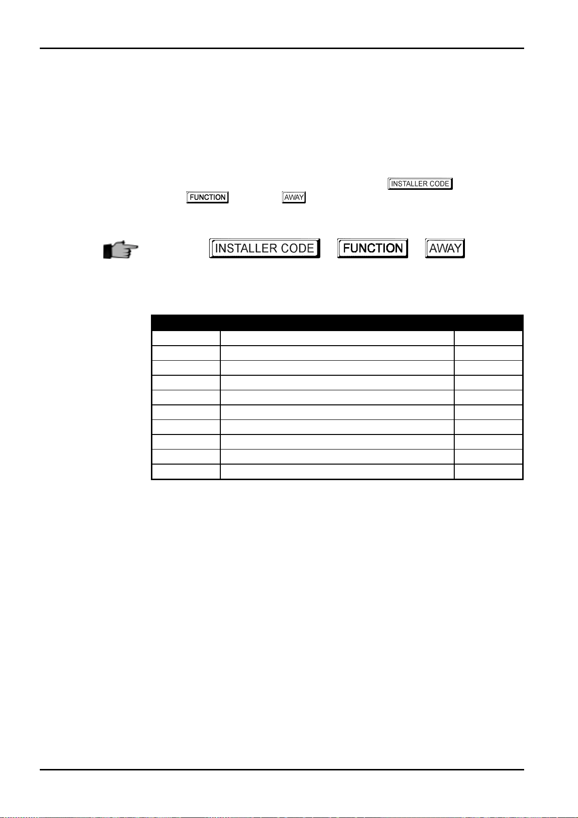
76
System Functions
This section explains the more advanced features that are required for testing and regular
maintenance of the system. Features such as Installer Code Functions, Master Code Functions
and Hold Down Functions are covered in this section.
Installer Code Functions
Installer Code Functions are designed to allow the installer to perform various system tests
without the need to know a Master Code.
To enter the required Installer Code function, enter the followed by the
required digit and the button. All available Installer Code functions are listed
in “Table 25: Installer Code Functions” outlined below.
These functions can only be carried out when the system is in the disarmed state.
Solution 862
+ +
Installation Manual
0
Function
0
1
2
3
4
5
6
7
8
9
Reserved
Description Page
Reserved
Set Number Of Days Until The First Test Report 77
Change Domestic Telephone Numbers 78
Change Telco Arm/Disarm Sequence 80
Setting STAY Mode 2 Zones 85
EDMSAT - Satellite Siren Service Mode 86
Turning Telephone Monitor Mode On/Off 87
Walk Test Mode 87
Event Memory Recall Mode 88
Reserved
Table 25: Installer Code Functions
ISSUE130 Electronics Design and Manufacturing Pty Limited
Page 77

System Functions 77
Set The Number Of Days Until The First Test Report
1
If you require the first test to report (Contact ID Event Code 602) the day after you are
installing the control panel and you have programmed the repeat interval between each test
report for every 7 days, you will need to set when the first test report will occur. If the first test
report is not set using this Installer Code Function, the first test report will be sent to the base
station receiver in the number of days programmed in the repeat interval. Refer to
"LOCATION 360 - 366" on page 187 for setting the test report time and repeat interval.
How To Set The First Test Report
Enter your
1.
Three beeps will be heard and the
Enter the to wait (1 - 15 days) until the first test report is required.
2.
Press the
3.
Two beeps will be heard and the
system will now return to the disarmed state.
Each time you enter Installer's Programming Mode after you have set w hen the first test
report will occur, the first test report time will default back to the repeat interval time
between each test report as set in “LOCATION 366”.
Test reports will not report if the Subscriber ID Number is 0000. The number of days
decrements by one at 2400 hours as set in "LOCATION 901 – 904" on page 210.
button when finished.
followed by 1and the button.
STAY
STAY
+
and
and
AWAY
+
1
+
AWAY
indicators will begin to flash.
indicators will extinguish. The
+
Example
If you programmed the repeat interval in the test reports for every seven days, but wish to have
the first test report to begin in two days time, follow the sequence outlined below;
1234+ 1
2
+
+
Electronics Design and Manufacturing Pty Limited ISSUE130
+
Page 78

78
Changing Domestic Phone Numbers
2
When the system has been set up for domestic dialling, this function allows the installer to
view and program the required telephone numbers that the system will call in the event of an
alarm. For a more detailed description, refer to Domestic Dialling on page 119 for further
information.
How To Change Domestic Phone Numbers
Solution 862
Installation Manual
Enter your followed by
1.
Three beeps will be heard and the
If there are telephone numbers already programmed, they will be displayed one digit at
a time via the remote codepad indicators. Refer to "Table 27: Codepad Indicators When
Changing Telephone Numbers" on page 79 for the indicators and their meanings.
If there are no telephone numbers programmed, a further two beeps will be heard after
entering this mode. These two beeps are normally heard after the last digit of the last
phone number has been displayed.
Enter all the digits for
2.
entered, the corresponding codepad indicators will illuminate.
If there is more than one telephone number, press the button followed by the
3.
button after the last digit of the telephone number. T his will insert a break between the
first telephone number and the second telephone number. If there is only one telephone
number, press the button to exit this mode.
Enter all the digits for
4.
entered, the corresponding codepad indicators will illuminate.
After the last digit of the second telephone number, press the
5.
mode unless a third telephone number is required. If there is a third telephone number
to be programmed, press the b utton followed by the 4
between the second telephone number and the third telephone.
STAY
, one digit at a time. You will notice as each digit is
, one digit at a time. Yo u will notice as each digit is
and the button.
2
AWAY
and
indicators will begin to flash.
button to exit this
button to insert a break
4
+
2
+ + +
Digit Required Number To Program Digit Required Number To Program
0
1
2
3
4
5
6
7
ISSUE130 Electronics Design and Manufacturing Pty Limited
0
1
2
3
4
5
6
7
Table 26: Domestic Dialling Digits
+ +
4
Four Second Pause
Break
8
9
10
11
12
15
+
8
9
Refer To Digit 0
Followed By
*
Followed By
*
Followed By
*
Followed By
*
Followed By
*
1
2
3
4
5
Page 79

System Functions 79
Example
If you wish to program two separate telephone numbers (9672 1777 and 9672 1233), follow
the sequence below and replace the telephone numbers mentioned in the manual with the
telephone numbers that you wish to program.
Digit
0
1
2
3
4
5
6
7
8
9
11
12
Pause
Break
15
1234+ 2
+
96721777
+
96721233
+
+ +
+
4
How To Disable Domestic Dialling
If at any time you wish to cancel domestic dialling for any reason (e.g.. You are moving house
and do not wish the system to continue calling your work place or mobile phone etc), you may
enter your followed by 2
by the
Zone 1
Indicator
V
V V
V V
Zone 2
Indicator
and the button to disable domestic dialling.
4
+
2
Zone 3
Indicator
V
V
V V
V V
Zone 4
Indicator
V
V V
Indicator
and the button, the button followed
+ + +
Zone 5
V
V V
Zone 6
Indicator
V
Zone 7
Indicator
V
+
4
Zone 8
Indicator
V
Indicator
MAINS
V
Table 27: Codepad Indicators When Changing Telephone Numbers
Electronics Design and Manufacturing Pty Limited ISSUE130
Page 80

80
Change Telco Arm/Disarm Sequence
3
This installer code function allows you to program the call forward sequence to automatically
operate when you arm the system in AWAY Mode. This feature is only available if your
telecommunication provider has the call forward option available.
When arming the system in AWAY Mode, the control panel will automatically dial the
telecommunication exchange to redirect all calls to your mobile phone, pocket pager or
answering service. When activated, your telephone will still allow outgoing calls to be made.
Contact your telecommunications provider for more information on call forward operations.
Digit Required Number To Program Digit Required Number To Program
0
1
2
3
4
5
6
7
0
1
2
3
4
5
6
7
Solution 862
8
9
10
11
12
Four Second Pause
Break
15
Installation Manual
8
9
Refer To Digit 0
Followed By
*
Followed By
*
Followed By
*
Followed By
*
Followed By
*
1
2
3
4
5
Digit
0
1
2
3
4
5
6
7
8
9
11
12
Pause
Break
15
Table 28: Telco Arm/Disarm Dialling Digits
Zone 1
Indicator
V
V V
V V
Zone 2
Indicator
V
V V
Zone 3
Indicator
V
V V
Zone 4
Indicator
V
V V
Zone 5
Indicator
V
V V
Zone 6
Indicator
V
Zone 7
Indicator
V
Zone 8
Indicator
V
Indicator
MAINS
V
Table 29: Codepad Indicators For Changing Telco Arm/Disarm Sequence
ISSUE130 Electronics Design and Manufacturing Pty Limited
Page 81

System Functions 81
How To Program Telco Arming Sequence - Easy Call Forward (No Answer On)
Enter your
1.
Three beeps will be heard and the
Press button
2.
Three beeps will be heard.
If a previous call forwarding sequence has already been programmed, the sequence will
be displayed one digit at a time via the remote codepad indicators. Refer to “Table 29:
Codepad Indicators For Changing Telco Arm/Disarm Sequence” on page 80 for the
indicators and their meanings.
If there is no call forward sequence programmed, a further two beeps will be heard after
entering this mode. T hese two beeps are normally heard after the last digit of the call
forward sequence has been displayed.
Enter
3.
calls to followed by
system will return to the disarmed state.
followed by the button to change the telco arming sequence.
1
161
followed by 3and the button.
STAY
followed by the you wish the control panel to divert all
and the b utton. Two beeps will be heard and the
2
1
and
+
AWAY
indicators will begin to flash.
+
3
+
Example
161
If you wish to automatically divert all unanswered incoming calls to another telephone number
(e.g.: 9672 1777) when the system is armed in AWAY Mode, follow the example sequence
below and replace the telephone number mentioned in the ma nual with the telephone number
that you wish to divert all calls to.
1234+ 3
+
+ +
1
+
How To Disable The Telco Arming Sequence
If at any time you wish to cancel the telco arming sequence, you may enter your
followed by 3and the button, followed by 1and the button,
then the
button followed by the 4and the button.
+ +
+
161+ 96721777
+
2
2
+
+
+
Electronics Design and Manufacturing Pty Limited ISSUE130
+ +
3
+
4
+
1
+
Page 82

82
How To Program The Telco Disarming Sequence – Easy Call Forward (No Answer Off)
Solution 862
Installation Manual
Enter your
1.
Three beeps will be heard and the
followed by the button to change the telco disarming sequence.
Press button
2.
Three beeps will be heard.
If a previous telco disarming sequence has already been programmed, the sequence will
be displayed one digit at a time via the remote codepad indicators. Refer to “Table 29:
Codepad Indicators For Changing Telco Arm/Disarm Sequence” on page 80 for the
indicators and their meanings.
If no telco disarming sequence has been programmed, a further two beeps will be heard
after entering this mode. T hese two beeps are normally heard after the last digit of the
call forward sequence has been displayed.
Enter
3.
Two beeps will be heard and the system will return to the disarmed state.
2
261 2
followed by 3and the button.
STAY
and the button.
+
2
and
AWAY
+
3
indicators will begin to flash.
+
261 2
How To Disable The Telco Disarming Sequence
If at any time you wish to cancel the telco disarming sequence, you may enter your
followed by 3and the button, followed by 2and the button,
then the
button followed by the 4and the button.
+
+ +
+ +
3
4
+
+
2
+
ISSUE130 Electronics Design and Manufacturing Pty Limited
Page 83

System Functions 83
How To Program Telco Arming Sequence - Easy Call Forward (Immediate On)
Enter your
1.
Three beeps will be heard and the
Press button
2.
Three beeps will be heard.
If a previous call forwarding sequence has already been programmed, the sequence will
be displayed one digit at a time via the remote codepad indicators. Refer to “Table 29:
Codepad Indicators For Changing Telco Arm/Disarm Sequence” on page 80 for the
indicators and their meanings.
If there is no call forward sequence programmed, a further two beeps will be heard after
entering this mode. T hese two beeps are normally heard after the last digit of the call
forward sequence has been displayed.
Enter
3.
calls to followed by
system will return to the disarmed state.
followed by the button to change the telco arming sequence.
1
121
followed by 3and the button.
STAY
followed by the you wish the control panel to divert all
and the b utton. Two beeps will be heard and the
2
1
and
+
AWAY
indicators will begin to flash.
+
3
+
Example
121
If you wish to automatically divert all incoming calls to another telephone number (e.g.: 9672
1777) when the system is armed in AWAY Mode, follow the example sequence below and
replace the telephone number mentioned in the manual with the telephone number that you
wish to divert all calls to.
1234+ 3
+
+ +
1
+
How To Disable The Telco Arming Sequence
If at any time you wish to cancel the telco arming sequence, you may enter your
followed by 3and the button, followed by 1and the button,
then the
button followed by the 4and the button.
+ +
+
121+ 96721777
+
2
2
+
+
+
Electronics Design and Manufacturing Pty Limited ISSUE130
+ +
3
+
4
+
1
+
Page 84

84
How To Program The Telco Disarming Sequence – Easy Call Forward (Immediate Off)
Solution 862
Installation Manual
Enter your
1.
Three beeps will be heard and the
followed by the button to change the telco disarming sequence.
Press button
2.
Three beeps will be heard.
If a previous telco disarming sequence has already been programmed, the sequence will
be displayed one digit at a time via the remote codepad indicators. Refer to “Table 29:
Codepad Indicators For Changing Telco Arm/Disarm Sequence” on page 80 for the
indicators and their meanings.
If no telco disarming sequence has been programmed, a further two beeps will be heard
after entering this mode. These two beeps are normally heard after the last digit of the
call forward sequence has been displayed.
Enter
3.
Two beeps will be heard and the system will return to the disarmed state.
2
221 2
followed by 3and the button.
STAY
and the button.
+
2
and
AWAY
+
3
indicators will begin to flash.
+
221 2
How To Disable The Telco Disarming Sequence
If at any time you wish to cancel the telco disarming sequence, you may enter your
followed by 3and the button, followed by 2and the button,
then the
button followed by the 4and the button.
+
+ +
+ +
3
4
+
+
2
+
ISSUE130 Electronics Design and Manufacturing Pty Limited
Page 85

System Functions 85
Setting STAY Mode 2 Zones
4
This function allows the installer to select which zones are to be automatically isolated when
the system is armed in STAY Mode 2.
Every time the system is armed in STAY Mode 2, the zones selected using this function will be
automatically isolated.
To arm the system in STAY Mode 2, hold down the
Refer to Hold Down Functions on page 107 or Arming The System In STAY Mode 2 on page
57 for more information.
button until two beeps are heard.
0
How To Set STAY Mode 2 Zones
Enter your
1.
Three beeps will be heard and the
* Enter the
2.
button. The corresponding
selected the zone to be automatically isolated every time you arm the system in STAY
Mode 2.
If more than one zone is required to be automatically isolated in STAY Mode 2, repeat
step 2 until all zones required have been selected.
Press the
3.
Two beeps will be heard and the system will return to the disarmed state. The zones
that were selected to be automatically isolated in STAY Mode 2 along with the
indicator will extinguish.
button to exit this function.
followed by 4and the button.
STAY
indicator will begin to flash.
that you wish to automatically isolate followed by the
ZONE
indicator will begin to flash to display that you have
+
4
+
STAY
Example
+
* As each zone has been selected to be isolated, the cor
begin to flash.
incorrectly entered followed by the button. This zone is now no longer
programmed to be isolated and the ZONE indicator will extinguish.
If you wish to select zones 2, 5 and 6 to be automatically isolated when arming in STAY Mode
2, follow the sequence below.
If a mistake has been made, press the zone number that was
1234+ 4
+
+ +
2
+ +
5
+ +
responding ZONE indicator will
+
+ +
6
Electronics Design and Manufacturing Pty Limited ISSUE130
Page 86

86
How To Disable STAY Mode 2 Zones
If at any time you wish to disable all zones selected to be automatically isolated for STAY
Mode 2, you may enter yo ur
by
the button.
followed by
Solution 862
and the button, followed
4
Installation Manual
5
+
4
+
+
Satellite Siren Service Mode
If an EDMSAT is connected to Output 1, this function will allow you to perform service work
on the system without triggering the satellite siren. The satellite siren will return to its normal
working state the next time the system is armed.
How To Enter Satellite Siren Service Mode
Enter your
1.
Three beeps will be heard.
followed by 5and the button.
+
5
+
ISSUE130 Electronics Design and Manufacturing Pty Limited
Page 87

System Functions 87
Turning Telephone Monitor Mode On/Off
6
Telephone monitor mode allows the remote codepad to be used for a visual representation of
data transmissions between the control panel and the base station receiver. The dialling
sequence is also shown in this mode.
The codepad will beep once every two seconds while telephone monitor mode active
regardless of whether the system is in Installer's Programming Mode or normal operating
mode. T he first five indicators are used to display the progressive steps for a transmission to
the base station receiver.
Zone Indicator Dialling Event
1
2
3
4
5
None
Table 30: Telephone Monitor Mode Indications
Telephone Line Seized
Dialling Phone Number
Handshake Received
Data Is Being Transmitted
Kiss-Off Received
Telephone Line Released
7
How To Turn Telephone Monitor Mode On
Enter your followed by
1.
Three beeps will be heard.
and the button.
6
How To Turn Telephone Monitor Mode Off
Enter your followed by
1.
Two beeps will be heard.
and the button.
6
+
6
+
Walk Test Mode
Walk test mode allows you to test detection devices to ensure that they are functioning
correctly. Before activating walk test mode, isolate any zones that are not required for testing.
Refer to Isolating Zones on page 60 for further information.
How To Enter Walk Test Mode
Enter your followed by
1.
Three beeps will be heard and the
codepad will beep once every second while the system is in walk test mode.
STAY
and the button.
7
AWAY
and
indicators will begin to flash. The
Unseal and seal the zones to be tested.
2.
The codepad will sound one long beep and the horn speaker will sound one short beep
every time a zone is sealed or unsealed.
Press the
3.
Two beeps will be heard and the
system has now returned to the disarmed state.
Electronics Design and Manufacturing Pty Limited ISSUE130
button to exit this function.
STAY
and
+
AWAY
indicators will extinguish. The
+
7
Page 88

88
Event Memory Recall Mode
8
This function allows you to playback the last forty events that have occurred to the system.
The event memory recall mode reports all alarms and arming/disarming of the system in the
AWAY Mode, STAY Mode 1 and STAY Mode 2. This function helps with trouble shooting
system faults. The events are displayed via the codepad indicators.
How To Enter The Event Memory Recall Mode
Solution 862
Installation Manual
Example
Enter your followed by
1.
Three beeps will be heard. The events will be played back via the codepad indicators in
reverse chronological order.
If the events were as follows:
Event No Event Description
1
2
3
4
Table 31: Event Memory Recall - Example Events
The event memory playback will report as follows:
Event No Codepad Indicator Event Description
4
3
2
1
All Indicators Off Except MAINS System Disarmed
Zone 4 + AWAY Indicator Illuminates Alarm In Zone 4
Zone 3 + AWAY Indicator Illuminates Alarm In Zone 3
AWAY Indicator Illuminates System Armed In AWAY Mode
System Armed In AWAY Mode
Alarm In Zone 3
Alarm In Zone 4
System Disarmed
and the button.
8
+
8
+
Table 32: Event Memory Recall - Example Event Playback
A beep and an illuminated codepad indicator indicate each event. Resetting a 24-hour alarm in
the disarmed state is indicated by one beep only. After the last event, three beeps will be heard
to indicate the end of playback. The replay of event memory can be terminated at any time by
pressing the
If the system is armed in STAY Mode 1 or STAY Mode 2, the STAY indicator will display
the event memory playback. There is no differentiation between arming the system in
STAY Mode 1 and STAY Mode 2.
If the control panel has been powered down, the memory of all events will be lost.
button.
Reserved
9
ISSUE130 Electronics Design and Manufacturing Pty Limited
Page 89

System Functions 89
Master Code Functions
Master Code Functions are designed to allow those users that have the appropriate priority
level to perform certain functions of a supervisory level. T hese functions can only be carried
out when the system is in the disarmed state.
The default Master Code is
the system to have multiple Master Codes. Refer to "User Code Priority" on page 153 for
more information.
To enter the required Master Code function, enter the followed by the required
digit and the button. All available Master Code functions are listed in “Table
33: Master Code Functions” outlined below.
2580
and is known as User Code 1. It is possible for
+ +
Function Description Page
0
1
2
3
4
5
6
7
8
9
Reserved
Changing and Deleting User Codes/Radio Codes 90/92
Changing Domestic Phone Numbers 94
Changing Telco Arm/Disarm Sequence 96
Setting STAY Mode 2 Zones 101
Turning Outputs On/Off 102
Setting The Date and Time 104
Walk Test Mode 105
Event Memory Recall Mode 106
Reserved
0
Table 33: Master Code Functions
Reserved
Electronics Design and Manufacturing Pty Limited ISSUE130
Page 90

90
Changing and Deleting User Codes
1
This function allows a Master Code holder to add/change or delete any of the system user
codes.
How To Add Or Change A User Code
Solution 862
Installation Manual
Enter your
1.
Three beeps will be heard and the
Enter the
2.
Two beeps will be heard and the corresponding
to "Table 35: Codepad Indicators Showing Relative User Numbers" on page 91.
Enter the digits required for the
3.
Two beeps will be heard and the
If you wish to change any further user codes, repeat this procedure as many times as
required.
+
When adding or changing user codes, this function will automatically terminate if a
button is not pr
beep indicates the code entered already exists or an incorrect user number has been
selected.
essed within sixty seconds or by pressing the button. One long
followed by 1and the button.
STAY
(1-8) that you wish to change followed by the button.
STAY
AWAY
and
followed by the button.
AWAY
and
+
indicators will begin to flash.
ZONE
indicator will illuminate. Refer
indicators will extinguish.
+
1
+ + +
Example
If you require to program user code number 2 as 4627, follow the steps outlined below and
remember to substitute the default Master Code (2580) with the Master Code that has been
programmed.
2580+ 1
2
+
+
+
4627
+
+
ISSUE130 Electronics Design and Manufacturing Pty Limited
Page 91

System Functions 91
How To Delete A User Code
Enter your followed by
1.
Three beeps will be heard and the
Enter the (1-8) that you wish to delete followed by the button.
2.
Two beeps will be heard and the corresponding
to "Table 35: Codepad Indicators Showing Relative User Numbers" on page 91.
Press the
3.
Two beeps will be heard and the
If you wish to delete any further user codes, repeat this procedure as many times as required.
button to delete the user code.
STAY
STAY
and the button.
1
AWAY
and
and
+
AWAY
indicators will begin to flash.
ZONE
indicators will extinguish.
+
1
indicator will illuminate. Refer
+ + +
When deleting user codes, this function will automatically terminate if a button is not
pressed within sixty seconds or by pressing the button. One long beep indicates
an incorrect user number has been selected.
Example
User
No
1
2
3
4
5
6
7
8
If you wish to delete user code number 3, follow the steps outlined below and remember to
substitute the default Master Code (2580) with the Master Code that has been programmed.
Zone 1
Indicator
V
Zone 2
Indicator
V
Table 35: Codepad Indicators Showing Relative User Numbers
2580+ 1
Zone 3
Indicator
V
+
3
Zone 4
Indicator
V
+
Zone 5
Indicator
V
+
Zone 6
Indicator
V
Zone 7
Indicator
V
Zone 8
Indicator
V
+
Electronics Design and Manufacturing Pty Limited ISSUE130
Page 92
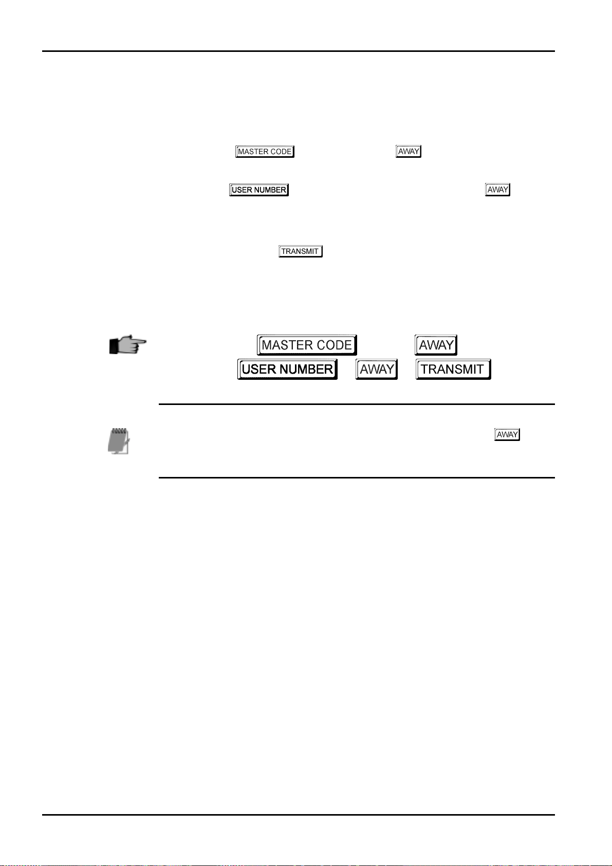
92
Changing and Deleting Remote Radio User Codes
1
This function allows a Master Code holder to add/change or delete any of the system user
codes.
How To Add Or Change A Remote Radio User Code
Solution 862
Installation Manual
Enter your
1.
Three beeps will be heard and the
Enter the
2.
Two beeps will be heard and the corresponding codepad indicators will illuminate.
Refer to "Table 36: Codepad Indicators Showing Relative Remote User Numbers" on
page 93.
Now press any of the buttons on the hand held transmitter.
3.
Two beeps will be heard and the
If you wish to change any further user codes, repeat this procedure as many times as
required.
+
When adding or changing remote radio user codes, this function will automatically
ter
minate if a button is not pressed within sixty seconds or by pressing the button.
One long beep indicates the code entered already exists or an incorrect user number has
been selected.
followed by 1and the button.
STAY
(9-16) that you wish to change followed by the button.
STAY
and
and
AWAY
+
AWAY
indicators will begin to flash.
indicators will extinguish.
+
1
+ +
ISSUE130 Electronics Design and Manufacturing Pty Limited
Page 93

System Functions 93
How To Delete A Remote Radio User Code
Enter your followed by
1.
Three beeps will be heard and the
Enter the
2.
Two beeps will be heard and the corresponding
to "Table 36: Codepad Indicators Showing Relative Remote User Numbers" on page 93.
Press the
3.
Two beeps will be heard and the
If you wish to delete any further remote radio user codes, repeat this procedure as many
times as required.
button to delete the user code.
(9-16) that you wish to delete followed by the button.
STAY
STAY
and the button.
1
AWAY
and
and
+
AWAY
indicators will begin to flash.
ZONE
indicators will extinguish.
+
1
indicator will illuminate. Refer
+ + +
When deleting remote radio user codes, this function will automatically terminate if a
button is not pressed within sixty seconds or by pressing the button. One long
beep indicates the an incorrect user number has been selected.
User
No
9
10
11
12
13
14
15
16
Zone 1
Indicator
Zone 2
Indicator
V V
V V
Table 36: Codepad Indicators Showing Relative Remote User Numbers
Zone 3
Indicator
V V
Zone 4
Indicator
V V
Zone 5
Indicator
V V
Zone 6
Indicator
V V
Zone 7
Indicator
V V
Zone 8
Indicator
MAINS
Indicator
V
Electronics Design and Manufacturing Pty Limited ISSUE130
Page 94

94
Changing Domestic Phone Numbers
2
When the system has been set up for domestic dialling, this function allows the Master Code
holder to view and program the required telephone numbers that the system will call in the
event of an alarm. For a more detailed description, refer to Domestic Dialling on page 119 for
further information.
How To Change Domestic Phone Numbers
Solution 862
Installation Manual
Enter your followed by
1.
Three beeps will be heard and the
If there are telephone numbers already programmed, they will be displayed one digit at
a time via the remote codepad indicators. Refer to "Table 38: Codepad Indicators When
Changing Domestic Telephone Numbers" on page 95 for the indicators and their
meanings.
If there are no telephone numbers programmed, a further two beeps will be heard after
entering this mode. These two beeps are normally heard after the last digit of the last
phone number has been displayed.
Enter all the digits for
2.
entered, the corresponding codepad indicators will illuminate.
If there is more than one telephone number, press the button followed by the
3.
button after the last digit of the telephone number. T his will insert a break between the
first telephone number and the second telephone number. If there is only one telephone
number, press the button to exit this mode.
Enter all the digits for
4.
entered, the corresponding codepad indicators will illuminate.
After the last digit of the second telephone number, press the
5.
mode unless a third telephone number is required. If there is a third telephone number
to be programmed, press the b utton followed by the 4
between the second telephone number and the third telephone.
STAY
and the button.
2
AWAY
and
, one digit at a time. You will notice as each digit is
, one digit at a time. Yo u will notice as each digit is
indicators will begin to flash.
button to exit this
button to insert a break
4
+
2
+ + +
Digit Required Number To Program Digit Required Number To Program
0
1
2
3
4
5
6
7
ISSUE130 Electronics Design and Manufacturing Pty Limited
0
1
2
3
4
5
6
7
Table 36: Domestic Dialling Digits
+ +
4
Four Second Pause
Break
+
8
9
*
#
Followed By
*
Followed By
*
Followed By
*
Followed By
*
8
9
1
2
3
4
Page 95

System Functions 95
Example
If you wish to program two separate telephone numbers (9672 1777 and 9672 1233), follow
the sequence below and replace the telephone numbers mentioned in the manual with the
telephone numbers that you wish to program.
Digit
0
1
2
3
4
5
6
7
8
9
*
#
Pause
Break
2580+ 2
+
96721777
+
96721233
+
+ +
+
4
How To Disable Domestic Dialling
If at any time you wish to cancel domestic dialling for any reason (e.g.. You are moving house
and do not wish the system to continue calling your work place or mobile phone etc), you may
enter your followed by 2
the
and the button to disable domestic dialling.
4
+
2
Zone 1
Indicator
V
V V
V V
Zone 2
Indicator
V
V V
Zone 3
Indicator
V
V V
Zone 4
Indicator
V
V V
and the button, the button followed by
+ + +
Zone 5
Indicator
V
Zone 6
Indicator
V
Zone 7
Indicator
V
4
Zone 8
Indicator
+
V
MAINS
Indicator
V
Table 38: Codepad Indicators When Changing Domestic Telephone Numbers
Electronics Design and Manufacturing Pty Limited ISSUE130
Page 96

96
Change Telco Arm/Disarm Sequence
3
This Master Code Function allows you to program the call forward sequence to automatically
operate when you arm the system in AWAY Mode. This feature is only available if your
telecommunication provider has the call forward option available.
When arming the system in AWAY Mode, the control panel will automatically dial the
telecommunication exchange to redirect all calls to your mobile phone, pocket pager or
answering service. When activated, your telephone will not ring but outgoing calls may still be
made. Contact your telecommunications provider for more information on call forward
operations.
Digit Required Number To Program Digit Required Number To Program
0
1
2
3
4
5
6
7
0
1
2
3
4
5
6
7
Solution 862
8
9
10
11
12
Four Second Pause
Break
15
Installation Manual
8
9
Refer To Digit 0
Followed By
*
Followed By
*
Followed By
*
Followed By
*
Followed By
*
1
2
3
4
5
Digit
0
1
2
3
4
5
6
7
8
9
11
12
Pause
Break
15
Table 38: Telco Arm/Disarm Dialling Digits
Zone 1
Indicator
V
V V
V V
Zone 2
Indicator
V
V V
Table 39: Codepad Indicators For Changing Telco Arm/Disarm Sequence
Zone 3
Indicator
V
V V
Zone 4
Indicator
V
V V
Zone 5
Indicator
V
V V
Zone 6
Indicator
V
Zone 7
Indicator
V
Zone 8
Indicator
V
Indicator
MAINS
V
ISSUE130 Electronics Design and Manufacturing Pty Limited
Page 97

System Functions 97
How To Program Telco Arming Sequence - Easy Call Forward (No Answer On)
Enter your
1.
Three beeps will be heard and the
Press button
2.
Three beeps will be heard.
If a previous telco disarming sequence has already been programmed, the sequence will
be displayed one digit at a time via the remote codepad indicators. Refer to “Table 39:
Codepad Indicators For Changing Telco Arm/Disarm Sequence” on page 96 for the
indicators and their meanings.
If there is no call forward sequence programmed, a further two beeps will be heard after
entering this mode. T hese two beeps are normally heard after the last digit of the call
forward sequence has been displayed.
Enter
3.
calls to followed by
system will return to the disarmed state.
1
161
followed by 3and the button.
STAY
followed by the button to change the telco arming sequence.
followed by the you wish the control panel to divert all
and the b utton. Two beeps will be heard and the
2
1
and
+
AWAY
indicators will begin to flash.
+
3
+
Example
161
If you wish to automatically divert all unanswered incoming calls to another telephone number
(e.g.: 9672 1777) when the system is armed in AWAY Mode, follow the example sequence
below and replace the telephone number mentioned in the ma nual with the telephone number
that you wish to divert all calls to.
2580+ 3
+
+ +
1
+
How To Disable The Telco Arming Sequence
If at any time you wish to cancel the telco arming sequence, you may enter your
and the button, followed by 1and the button, then the
followed by
button followed by the
3
and the button.
4
+ +
+
161+ 96721777
+
2
2
+
+
+ +
Electronics Design and Manufacturing Pty Limited ISSUE130
+ +
3
4
+
1
+
Page 98

98
How To Program The Telco Disarming Sequence – Easy Call Forward (No Answer Off)
Solution 862
Installation Manual
Enter your
1.
Three beeps will be heard and the
followed by the button to change the telco disarming sequence.
Press button
2.
Three beeps will be heard.
If a previous telco disarming sequence has already been programmed, the sequence will
be displayed one digit at a time via the remote codepad indicators. Refer to “Table 39:
Codepad Indicators For Changing Telco Arm/Disarm Sequence” on page 96 for the
indicators and their meanings.
If no telco disarming sequence has been programmed, a further two beeps will be heard
after entering this mode. These two beeps are normally heard after the last digit of the
call forward sequence has been displayed.
Enter
3.
Two beeps will be heard and the system will return to the disarmed state.
2
261 2
followed by 3and the button.
STAY
and the button.
+
2
and
+
AWAY
indicators will begin to flash.
+
3
261 2
How To Disable The Telco Disarming Sequence
If at any time you wish to cancel the telco disarming sequence, you may enter your
followed by 3and the button, followed by 2and the button,
then the
button followed by the 4and the button.
+
+ +
+ +
3
4
+
+
2
+
ISSUE130 Electronics Design and Manufacturing Pty Limited
Page 99

System Functions 99
How To Program Telco Arming Sequence - Easy Call Forward (Immediate On)
Enter your
1.
Three beeps will be heard and the
Press button
2.
Three beeps will be heard.
If a previous call forwarding sequence has already been programmed, the sequence will
be displayed one digit at a time via the remote codepad indicators. Refer to “Table 39:
Codepad Indicators For Changing Telco Arm/Disarm Sequence” on page 96 for the
indicators and their meanings.
If there is no call forward sequence programmed, a further two beeps will be heard after
entering this mode. T hese two beeps are normally heard after the last digit of the call
forward sequence has been displayed.
Enter
3.
calls to followed by
system will return to the disarmed state.
1
121
followed by 3and the button.
STAY
followed by the button to change the telco arming sequence.
followed by the you wish the control panel to divert all
and the b utton. Two beeps will be heard and the
2
1
and
+
AWAY
indicators will begin to flash.
+
3
+
Example
121
If you wish to automatically divert all incoming calls to another telephone number (e.g.: 9672
1777) when the system is armed in AWAY Mode, follow the example sequence below and
replace the telephone number mentioned in the manual with the telephone number that you
wish to divert all calls to.
2580+ 3
+
+ +
1
+
How To Disable The Telco Arming Sequence
If at any time you wish to cancel the telco arming sequence, you may enter your
and the button, followed by 1and the button, then the
followed by
button followed by the
3
and the button.
4
+ +
+
121+ 96721777
+
2
2
+
+
+
Electronics Design and Manufacturing Pty Limited ISSUE130
+ +
3
+
4
+
1
+
Page 100

100
How To Program The Telco Disarming Sequence – Easy Call Forward (Immediate Off)
Solution 862
Installation Manual
Enter your
1.
Three beeps will be heard and the
followed by the button to change the telco disarming sequence.
Press button
2.
Three beeps will be heard.
If a previous telco disarming sequence has already been programmed, the sequence will
be displayed one digit at a time via the remote codepad indicators. Refer to “Table 39:
Codepad Indicators For Changing Telco Arm/Disarm Sequence” on page 96 for the
indicators and their meanings.
If no telco disarming sequence has been programmed, a further two beeps will be heard
after entering this mode. These two beeps are normally heard after the last digit of the
call forward sequence has been displayed.
Enter
3.
Two beeps will be heard and the system will return to the disarmed state.
2
221 2
followed by 3and the button.
STAY
and the button.
+
2
and
+
AWAY
indicators will begin to flash.
+
3
221 2
How To Disable The Telco Disarming Sequence
If at any time you wish to cancel the telco disarming sequence, you may enter your
followed by 3and the button, followed by 2and the button,
then the
button followed by the 4and the button.
+
+ +
+ +
3
4
+
+
2
+
ISSUE130 Electronics Design and Manufacturing Pty Limited
 Loading...