

EDM Solution 6+6 Wireless-AE Installation Manual

Solution 6+6 Wireless - AE
Installation Manual
ISSUE 1.20


S
This page has been included for you to cut out and insert into the spine
MA660I
olution
of the folder
6+6
Wireless
AE
Installation
Manual
ISSUE 1.20
(61-2) 9672 1233


Solution 6+6 Wireless - AE
Installation Manual
Copyright 1997 by Electronics Desi gn and Ma nuf ac turing Pty Limited,
SYDNEY, AUSTRALIA
Document Part Number MA660I
Document ISSUE 1.20
Printed 02 July 2001
This documentation is provided to suit
Alarm Link Form - Software Version 1.00 = CRO1V10
Solution 6+6 Wireless - AE (CC660/LP660)
Firmware Revision 1.00 – 1.02
Hardware Revision A
Copyright Notice
All rights reserved. No part of this publication may be reproduced, transmitted or stored in a retrieval system in any form or
by any means, electronic, mechanical, photocopying, recording, or otherwise, without the prior written permission of
Electronics Design and Manufacturing Pty Limited.
Trademarks
Throughout this document trademark names may have been used. Rather than put a trademark symbol in every occurrence
of a trademark name, we state that we are using the names only in an editorial fashion and to the benefit of the trademark
owner with no intention of infringeme nt of the trademark.
Notice of Liability
While every precaution has been taken in the preparation of this document, neither Electronics Design and Manufacturing
Pty Limited nor any of its official representatives shall have any liability to any person or entity with respect to any
liability, loss or damage caused or alleged to be caused directly or indirectly by the information contained in this book.
Electronics Design and Manufacturing Pty Limited reserves the right to make changes to features and specifications at any
time without prior notification in the interest of ongoing product development and improvement.


Table Of Contents
Introduction_____________________________________________________________________ 15
Introduction__________________________________________________________________________ 16
Features _____________________________________________________________________________ 17
Quick Start___________________________________________________________________________ 18
Zone Defaults ________________________________________________________________________________ 18
Programming____________________________________________________________________ 19
Programming_________________________________________________________________________ 20
Programming With The Remote Codepad_________________________________________________ 21
Programming With The Hand Held Programmer___________________________________________ 22
Programming With The Programming Key________________________________________________ 23
Programming Option Bits ______________________________________________________________ 23
Installer’s Programming Commands _____________________________________________________ 24
Command 958 - Enable/Disable Zone Status Mode ___________________________________________________ 25
Command 959 - Test Programming Key ___________________________________________________________ 26
Command 960 - Exit Installer's Programming Mode __________________________________________________ 26
Command 961 - Reset Control Panel Back To Factory Default Settings ___________________________________27
Command 962 - Copy Control Panel Memory To Programming Key _____________________________________ 27
Command 963 - Copy From Programming Key To Control Panel________________________________________ 28
Command 964 - Erase Programming Key __________________________________________________________ 29
Command 965 - Set Up Domestic Dialling Format ___________________________________________________ 30
Command 966 - Enable/Disable Automatic Stepping Of Locations_______________________________________ 31
Command 999 - Display Software Version Number __________________________________________________ 32
Disable Factory Default ________________________________________________________________________ 32
Defaulting The Control Panel ____________________________________________________________________ 33
System Indicators and Operations ___________________________________________________ 35
System Indicators and Operations________________________________________________________ 36
CP5 Eight Zone Codepad_______________________________________________________________ 36
Zone Indicators _______________________________________________________________________________ 36
AWAY Indicator______________________________________________________________________________ 36
STAY Indicator_______________________________________________________________________________ 36
MAINS Indicator _____________________________________________________________________________ 37
FAULT Indicator _____________________________________________________________________________ 37
Audible Indicators_____________________________________________________________________________ 37
CP5 Eight Zone LCD Codepad __________________________________________________________ 38
Zone Indicators _______________________________________________________________________________ 38
AWAY Indicator______________________________________________________________________________ 38
STAY Indicator_______________________________________________________________________________ 38
System Disarmed _____________________________________________________________________________ 39
MAINS Indicator _____________________________________________________________________________ 39
Zone Isolating Mode___________________________________________________________________________ 39
FAULT Indicator _____________________________________________________________________________ 39
Programming Mode ___________________________________________________________________________ 39
Off Indicator/Zone Sealed_______________________________________________________________________ 40
On Indicator/Zone In Alarm _____________________________________________________________________40
Audible Indicators_____________________________________________________________________________ 40
System Operations_____________________________________________________________________ 41
Arming The System In AWAY Mode _____________________________________________________________ 41
Forced Arming _____________________________________________________________________________ 41
Disarming The System From AWAY Mode_________________________________________________________ 41
Arming The System In STAY Mode ______________________________________________________________ 42
Forced Arming _____________________________________________________________________________ 42
Disarming The System From STAY Mode__________________________________________________________ 43

Codepad Duress Alarm_________________________________________________________________________ 44
Codepad Panic Alarm__________________________________________________________________________ 44
Codepad Fire Alarm___________________________________________________________________________ 44
Codepad Medical Alarm________________________________________________________________________ 44
Isolating Zones ________________________________________________________________________ 45
Standard Isolating_____________________________________________________________________________ 45
Code To Isolate_______________________________________________________________________________ 46
Fault Analysis Mode____________________________________________________________________47
Fault Descriptions_____________________________________________________________________________ 48
Low Battery _______________________________________________________________________________ 48
Date and Time______________________________________________________________________________ 48
Sensor Watch ______________________________________________________________________________ 48
Horn Speaker Monitor _______________________________________________________________________ 48
Reserved__________________________________________________________________________________ 48
2
E
Fault___________________________________________________________________________________ 48
Zone Transmitter Low Battery _________________________________________________________________ 48
Communication Failure ______________________________________________________________________ 49
AC Mains Failure___________________________________________________________________________ 49
System Functions_________________________________________________________________ 51
System Functions ______________________________________________________________________ 52
Installer Code Functions ________________________________________________________________52
Fault Analysis Mode_________________________________________________________________________ 53
How To Enter Fault Analysis Mode_____________________________________________________________ 53
Enable/Disable Wireless Zones ________________________________________________________________ 54
Set The Number Of Days Until The First Test Report_______________________________________________ 55
Event Memory Recall Mode___________________________________________________________________ 56
Walk Test Mode ____________________________________________________________________________ 57
Satellite Siren Service Mode___________________________________________________________________ 57
Initiate Modem Call _________________________________________________________________________ 57
How To Initiate A Modem Call ________________________________________________________________ 57
Turning Telephone Monitor Mode On/Off________________________________________________________ 58
Reserved__________________________________________________________________________________ 58
Send Test Report____________________________________________________________________________ 58
Master Code Functions _________________________________________________________________59
Arm Or Disarm Both Areas At The Same Time____________________________________________________ 59
Changing and Deleting User Codes _____________________________________________________________ 60
Changing and Deleting Remote Radio User Codes _________________________________________________ 62
Changing Domestic Phone Numbers ____________________________________________________________ 64
Event Memory Recall Mode___________________________________________________________________ 65
Walk Test Mode ____________________________________________________________________________ 66
Fault Analysis Mode_________________________________________________________________________ 67
Setting The Date and Time____________________________________________________________________ 68
Turn Day Alarm On and Off___________________________________________________________________ 68
Reset Latching Outputs_______________________________________________________________________ 69
Initiate Modem Call _________________________________________________________________________ 69
User Code Functions – Partitioned Systems Only____________________________________________ 70
Arm Or Disarm Both Areas At The Same Time____________________________________________________ 70
Hold Down Functions___________________________________________________________________71
Arm The System In AWAY Mode______________________________________________________________ 71
Arm The System In STAY Mode_______________________________________________________________ 71
Horn Speaker Test __________________________________________________________________________ 71
Bell Test __________________________________________________________________________________ 71
Strobe Test ________________________________________________________________________________ 72
Turning Day Alarm On and Off ________________________________________________________________ 72
Fault Analysis Mode_________________________________________________________________________ 72
Initiate A Modem Call _______________________________________________________________________ 73
Reset Latching Outputs_______________________________________________________________________ 73
Codepad ID & Beeper Tone Change ____________________________________________________________ 73
Initiate A Test Report________________________________________________________________________ 73

Remote Operations _______________________________________________________________ 75
Remote Operations ____________________________________________________________________ 76
Remote Radio Transmitter Operation ____________________________________________________ 76
Arming Via Transmitter In AWAY Mode ________________________________________________________ 76
Disarming Via Transmitter From AWAY Mode ___________________________________________________ 76
Arming Via Transmitter In STAY Mode _________________________________________________________ 77
Disarming Via Transmitter From STAY Mode ____________________________________________________ 77
Panic Alarm Via Transmitter __________________________________________________________________ 77
Turning An Output On Via Transmitter __________________________________________________________ 77
Turning An Output Off Via Transmitter__________________________________________________________ 77
Remote Arming Via The Telephone ______________________________________________________ 78
Upload/Download Via Alarm Link Software_______________________________________________ 79
Remote Connect ______________________________________________________________________________ 79
Remote Connect With Customer Control _________________________________________________________ 79
Remote Connect Without Call Back Verification___________________________________________________ 79
Remote Connect With Call Back Verification _____________________________________________________ 80
Dialler Reporting Formats _________________________________________________________ 81
Dialler Reporting Formats______________________________________________________________ 82
Contact ID Format ____________________________________________________________________________ 82
Point ID Codes _______________________________________________________________________________ 83
Securitel ____________________________________________________________________________________ 84
Domestic Reporting Format _____________________________________________________________________ 85
Domestic Dialling Function ___________________________________________________________________ 85
Acknowledge Domestic Dialling _________________________________________________________________ 85
Programming Domestic Reporting ______________________________________________________________ 86
Disable Domestic Dialling ______________________________________________________________________ 87
Basic Pager Reporting Format ___________________________________________________________________ 88
Base Station Information __________________________________________________________ 89
Base Station Information _______________________________________________________________ 90
Primary Telephone Number _____________________________________________________________________ 91
Secondary Telephone Number ___________________________________________________________________ 91
Call Back Telephone Number____________________________________________________________________ 91
Dialling Format_______________________________________________________________________________ 92
Handshake Tone ______________________________________________________________________________ 92
Transmission Format___________________________________________________________________________ 93
Reserved ____________________________________________________________________________________93
Subscriber ID Number _________________________________________________________________________ 93
Ring Count __________________________________________________________________________________ 94
Answering Machine Bypass _____________________________________________________________________ 94
User Codes______________________________________________________________________ 95
Access Codes _________________________________________________________________________ 96
Installer Code ________________________________________________________________________________ 96
User Codes __________________________________________________________________________________ 96
Remote Radio User Codes ______________________________________________________________________ 96
Teaching Radio User Codes ___________________________________________________________________ 96
Default User Codes____________________________________________________________________________ 97
User Code Priority ____________________________________________________________________________ 98
Arm and Disarm ____________________________________________________________________________ 98
Arm Only _________________________________________________________________________________ 98
Patrolman Code_____________________________________________________________________________ 98
Arm and Disarm + Code To Isolate _____________________________________________________________ 98
Patrolman Code + Code To Isolate______________________________________________________________98
Arm and Disarm + Master Code Functions________________________________________________________98
Arm and Disarm + Master Code Functions + Code To Isolate_________________________________________ 98
Code Retries _________________________________________________________________________________ 99

Zone Information________________________________________________________________ 101
Zone Information_____________________________________________________________________102
Day Alarm Mask ____________________________________________________________________________ 102
Day Alarm Resetting _______________________________________________________________________ 102
Day Alarm Latching________________________________________________________________________ 102
Day Alarm Operation _________________________________________________________________________ 103
Day Alarm When Partitioned _________________________________________________________________ 103
EOL Resistor Value __________________________________________________________________________ 104
Connections Of Split EOL Resistors Using N/O Contacts_____________________________________________ 105
Zone Programming ___________________________________________________________________106
Zone Operating Information__________________________________________________________________ 106
Zone Reporting Options _____________________________________________________________________ 106
Tamper Zones_______________________________________________________________________________ 107
Zone Defaults _______________________________________________________________________________ 108
Zone Types_________________________________________________________________________________ 108
Instant Zone ______________________________________________________________________________ 108
Handover Zone____________________________________________________________________________ 108
Delay-1 Zone _____________________________________________________________________________ 108
Delay-2 Zone _____________________________________________________________________________ 108
Reserved_________________________________________________________________________________ 108
Reserved_________________________________________________________________________________ 109
Instant Zone + Isolated In STAY Mode _________________________________________________________ 109
Handover Zone + Isolated In STAY Mode_______________________________________________________ 109
Delay-1 Zone + Isolated In STAY Mode ________________________________________________________ 109
Delay-2 + Isolated In STAY Mode_____________________________________________________________ 109
Reserved_________________________________________________________________________________ 109
Keyswitch Zone ___________________________________________________________________________ 109
24 Hour Burglary Zone______________________________________________________________________ 109
24 Hour Fire Zone _________________________________________________________________________ 109
Chime Zone ______________________________________________________________________________ 109
Zone Not Used ____________________________________________________________________________ 109
Zone Options _______________________________________________________________________________ 110
Lockout Siren & Lockout Dialler______________________________________________________________ 110
Silent Alarm ______________________________________________________________________________ 111
Sensor Watch _____________________________________________________________________________ 111
Keyswitch Zone Options ______________________________________________________________________ 112
Latching Arm and Disarm In AWAY Mode _____________________________________________________ 112
Latching Arm In AWAY Mode _______________________________________________________________ 112
Latching Disarm From AWAY Mode Or STAY Mode_____________________________________________ 112
Latching Arm and Disarm In STAY Mode ______________________________________________________ 112
Latching Arm In STAY Mode ________________________________________________________________ 112
Latching Disarm From AWAY Mode Or STAY Mode_____________________________________________ 112
Momentary Arm and Disarm In AWAY Mode ___________________________________________________ 113
Momentary Arm In AWAY Mode_____________________________________________________________ 113
Momentary Disarm From AWAY Mode Or STAY Mode___________________________________________ 113
Momentary Arm and Disarm In STAY Mode ____________________________________________________ 113
Momentary Arm In STAY Mode ______________________________________________________________ 113
Momentary Disarm From AWAY Mode Or STAY Mode___________________________________________ 113
Zone Pulse Count ____________________________________________________________________________ 114
Zone Pulse Count Handover__________________________________________________________________ 114
Zone Pulse Count Time _______________________________________________________________________ 114
Reporting Options _______________________________________________________________ 115
Reporting Options ____________________________________________________________________ 116
Report Options 1_____________________________________________________________________________ 116
Enable Zone Bypass Reports _________________________________________________________________ 116
Enable Zone Bypass Restore Reports___________________________________________________________ 116
Enable Zone Trouble Reports_________________________________________________________________ 116
Enable Zone Trouble Restore Report ___________________________________________________________ 116
Report Options 2_____________________________________________________________________________ 117
Enable Duress Reports ______________________________________________________________________ 117
Enable Panic, Medical & Fire Reports __________________________________________________________ 117
Enable Access Denied Reports________________________________________________________________ 117

Enable Test Reports ________________________________________________________________________ 117
Report Options 3_____________________________________________________________________________ 118
Enable AC Mains Fail Reports ________________________________________________________________ 118
Enable Low Battery Reports__________________________________________________________________118
Enable Sensor Watch Reports_________________________________________________________________ 118
Enable Opening/Closing Reports ______________________________________________________________ 118
Test Reports ________________________________________________________________________________ 119
Programmable Outputs___________________________________________________________ 121
Programmable Outputs _______________________________________________________________ 122
Output Defaults______________________________________________________________________________ 122
Redirecting Outputs To The Codepad Buzzer_______________________________________________________123
Output Event Types___________________________________________________________________________124
Output Polarity ______________________________________________________________________________ 131
Output Not Used___________________________________________________________________________131
Normally Open, Going Low __________________________________________________________________ 131
Normally Open, Pulsing Low _________________________________________________________________ 131
Normally Open, One Shot Low________________________________________________________________ 131
Normally Open, One Shot Low With Retrigger ___________________________________________________ 131
Normally Open, One Shot Low With Reset ______________________________________________________ 131
Normally Open, One Shot Low With Alarm______________________________________________________132
Normally Open, Latching Low ________________________________________________________________ 132
Normally Low, Going Open __________________________________________________________________ 132
Normally Low, Pulsing Open _________________________________________________________________ 132
Normally Low, One Shot Open________________________________________________________________ 132
Normally Low, One Shot Open With Retrigger ___________________________________________________ 132
Normally Low, One Shot Open With Reset ______________________________________________________132
Normally Low, One Shot Open With Alarm______________________________________________________132
Normally Low, Latching Open________________________________________________________________ 132
Timing Of Outputs ___________________________________________________________________________ 133
Pulsing Polarities_____________________________________________________________________________ 133
One Shot Polarities ___________________________________________________________________________ 134
System Event Timers _____________________________________________________________ 135
System Event Timers _________________________________________________________________ 136
How To Program Entry/Exit Timers____________________________________________________________ 136
Entry Time _________________________________________________________________________________ 136
Entry Timer 1 _______________________________________________________________________________ 136
Entry Timer 2 _______________________________________________________________________________ 136
Exit Time __________________________________________________________________________________ 137
Entry Guard Timer For STAY Mode _____________________________________________________________ 137
Sensor Watch Time___________________________________________________________________________ 137
Codepad Lockout Time________________________________________________________________________ 138
Siren Run Time______________________________________________________________________________ 138
Siren Sound Rate_____________________________________________________________________________138
Swinger Shutdown Count ______________________________________________________________________ 139
System Time________________________________________________________________________________140
Setting The Date and Time ___________________________________________________________________ 140
Options Bits ____________________________________________________________________ 141
Dialler Options ______________________________________________________________________ 142
Dialler Options 1_____________________________________________________________________________ 142
Enable Dialler Reporting Functions ____________________________________________________________ 142
Disable Dialler Reporting Functions____________________________________________________________ 142
Enable Remote Arming Via The Telephone______________________________________________________ 142
Enable Upload/Download Via Alarm Link_______________________________________________________ 142
Terminate “Alarm Link” Session On Alarm ______________________________________________________ 142
Dialler Options 2_____________________________________________________________________________ 143
Send Open/Close Reports Only If A Previous Alarm Has Occurred ___________________________________ 143
Enable First To Open, Last To Close Reporting When Partitioned ____________________________________ 143
Send Open/Close Reports When In STAY Mode__________________________________________________ 143
Delay Siren Until Transmission Complete _______________________________________________________ 143

System Options 1 ____________________________________________________________________________ 144
Enable Forced Arming ______________________________________________________________________ 144
Enable EDM Smart Lockout__________________________________________________________________ 144
Enable Monitoring Of Horn Speaker ___________________________________________________________ 144
Allow Horn Speaker Beeps For Remote Control Operations_________________________________________ 144
System Options 2 ____________________________________________________________________________ 145
Enable Radio Key/Keyswitch Interface or Night Arm Station________________________________________ 145
Enable Handover Delay To Be Sequential_______________________________________________________ 145
Enable Codepad Panic To Be Silent____________________________________________________________ 145
Enable Access Denied To Be Silent____________________________________________________________ 145
System Options 3 ____________________________________________________________________________ 146
Enable Data Output To Display Data For Area 1 - Partitioned Systems Only ____________________________ 146
Enable Resetting Of Sirens From All Areas (Partitioned Systems Only)________________________________ 146
Ignore AC Mains Fail Indication ______________________________________________________________ 146
Enable Zone Pulse Count Handover____________________________________________________________ 146
System Options 4 ____________________________________________________________________________ 147
Enable AC Fail In 1 Hour____________________________________________________________________ 147
Extend Time To Wait For Handshake From 30 Seconds To 1 Minute__________________________________ 147
Enable Control Panel To Power Up In The Disarmed State__________________________________________ 147
Enable Remote Radio Zone Low Battery Reports _________________________________________________ 147
Consumer Options 1__________________________________________________________________________ 148
Send Test Reports Only If The System Is Armed__________________________________________________ 148
Enable Operation Of Siren & Strobe In STAY Mode ______________________________________________ 148
Enable Answering Machine Bypass Only When Armed ____________________________________________ 148
Enable Codepad Extinguish Mode _____________________________________________________________ 148
Consumer Options 2__________________________________________________________________________ 149
Enable Single Button Arming In AWAY Mode Or STAY Mode _____________________________________ 149
Enable Single Button Disarming From STAY Mode_______________________________________________ 149
Enable Alarm Memory Reset On Disarm________________________________________________________ 149
System Options 5 ____________________________________________________________________________ 149
Enable Internal Crystal To Keep Time__________________________________________________________ 149
Partitioning_____________________________________________________________________ 151
Partitioning__________________________________________________________________________152
Master Partitioned Codepad Indicators____________________________________________________________ 152
Zone Indicators____________________________________________________________________________ 152
Area ON/OFF Indicators ____________________________________________________________________ 152
Area Display Indicators _____________________________________________________________________ 152
Status Indicators ___________________________________________________________________________ 152
Operating Codepads In Partitioning ______________________________________________________________ 153
Operating From A “CP-5 Area Addressable (CP500A)” Codepad ____________________________________ 153
Operating From A “CP-5 Master Partitioned (CP500P)” Codepad ____________________________________ 153
Securitel and Partitioning ______________________________________________________________________ 154
Subscriber ID Number ________________________________________________________________________ 154
Open/Close Reports __________________________________________________________________________ 155
Dialler Options 2 ____________________________________________________________________________ 155
Send Open/Close Reports Only If A Previous Alarm Has Occurred ___________________________________ 155
Enable First To Open, Last To Close Reporting When Partitioned ____________________________________ 155
Send Open/Close Reports When In STAY Mode__________________________________________________ 155
Delay Siren Until Transmission Complete_______________________________________________________ 155
Zone Allocations_____________________________________________________________________________ 156
Zones Allocations For Area 1___________________________________________________________________ 156
Zones Allocations For Area 2___________________________________________________________________ 156
Tamper Zone Allocations ______________________________________________________________________ 157
User Code Allocations ________________________________________________________________________ 157
Remote Radio User Code Allocations ____________________________________________________________ 158
Codepad Connections For Partitioning ___________________________________________________159
Optional Equipment______________________________________________________________ 161
Optional Equipment___________________________________________________________________162

Terminals and Descriptions _______________________________________________________ 169
Terminal Definitions and Descriptions ___________________________________________________ 170
Glossary Of Terms ___________________________________________________________________ 171
Solution 6+6 Wireless - AE Wiring Diagram ______________________________________________ 173
Solution 6+6 Wireless - AE Component Overlay___________________________________________ 174
Connection Diagram For Radio Receiver_________________________________________________ 175
Telecom Connection Diagrams _________________________________________________________ 176
Appendices_____________________________________________________________________ 177
Appendix A _________________________________________________________________________ 178
Telephone Anti-Jamming ______________________________________________________________________ 178
Appendix B _________________________________________________________________________ 179
Test Reports Only When Armed_________________________________________________________________ 179
Specifications___________________________________________________________________ 181
Warranty Statement__________________________________________________________________ 182
Specifications________________________________________________________________________ 182
Software Version Number______________________________________________________________________ 182
Advice To Users _____________________________________________________________________________ 183
New Zealand Telepermit Notes__________________________________________________________________183
Programming Sheets_____________________________________________________________ 185
Index _________________________________________________________________________ 191


This section includes the following;
• Introduction
• Features
Introduction
• Quick Start

16
Solution 6+6 Wireless - AE Installation Manual
Introduction
Congratulations on selecting the Solution 6+6 Wireless - AE contro l panel for your
installation. So that you ca n o bta in the mo st fr om your uni t, we su ggest t hat yo u ta ke the ti me
to read through this manual and familiarise yo urself with the n umerous outstand ing operating
and installation features of this system.
You will notice that in all aspects of planning, engineering, styling, operation, convenience and
adaptability, we have sought to anticipate your every possible requirement. Programming
simplicity and speed have been some of the major considerations and we believe that our
objectives in this area have been more than satisfied.
This installation manual will explain all aspects of programming the
Wireless - AE
parameters and options are detailed, however, suitability is left up to the individual. Every
control panel can be tailored to meet all requirements quic kly and easily. The programming
simplicity will make your installation quick, accurate and rewarding each and every time.
The
Solution range of control panels are very popular amongst thousands of people
throughout many countries of the world, all who have various levels of technical aptitude and
ability. We have tried to aim this installation manual to all levels of readers.
As the
Solution control panels continue to be improved over the years, they have become
very powerful. Some of its early first-time users have advanced to true "power users" and we
need to address their needs too, while maintaining the simplicity of the manual and the product.
control panel from factory default to final commissioning. All system
Solution 6+6
ISSUE120.DOC Electronics Design and Manufacturing Pty Limited

Introduction 17
Features
The Solution 6+6 Wireless - AE security system uses the very latest in microprocessor
technology to provide you with more useful features and superior reliability and performance.
Following is a list of the main features that the control panel will provide.
Eight Programmable User Codes
Eight Additional Radio Remote User Codes
Codepad Duress, Panic, Fire, Medical Alarms
ST AY Mode and AWAY Mode Operation
Entr y and Exit Warning Beeper
Six Fully Programmable Hard Wired Or Wireless Burglary Zones
Six 24 Hour Tamper Zones
Partitionable To 2 Areas
Zo ne Lo ckout
Se nsor Watch
Da y Alarm
Dynamic Battery Testing
Re mot e Ar mi ng
Answering Machine Bypass
AC Fail and System Fault Indicators
Event Memory Recall
Walk Test Mode
Upload/Download Programmable
Monitored Siren Output
Strobe Output
Relay Output
EDMSAT – Satellite Siren Compatible
Separate Fire Alarm Sound
Securitel Co mpatible
Electronics Design and Manufacturing Pty Limited ISSUE120.DOC
18
Solution 6+6 Wireless - AE Installation Manual
Quick Start
The following steps will enable you to use the Solution 6+6 Wireless - AE control
panel with the factory default values. The factory default values allow the control panel to
communicate in the Contact ID format.
1. Connect the AC plug pack to the control panel.
2. Check the operation of the red overload indicator (LD1) on the PCB. In normal
operation the indicator will not illuminate. The
the
AWAY indicator. The system is now in the armed state.
3. Enter the factory default Master Code
AWAY indicator will extinguish. The system is now in the disarmed state. Installer’s
Programming Mode can now be accessed.
4. The back-up battery should now be connected.
5. Enter the factory default Installer Code
STAY and AWAY indicators will now flash simultaneously to indicate that you have
now entered Installer’s Programming Mode.
6. Enter the Primary Telephone Number followed by the Secondary Telephone Number
and the Subscriber ID Number.
7. Set the time for the test reports if required. Any other programming changes required
may also be made, otherwise the factory default settings will be used.
8. Enter Installer’s Command
Programming Mode. The system will now return to the disarmed state and is now ready
for use. Refer to “Installer’s Programming Commands” on page 24 for more
information
9. Use the Master Code to set the date and time.
960 followed by the button to exit Installer’s
2580 followed by the button. The
1234 followed by the button. The
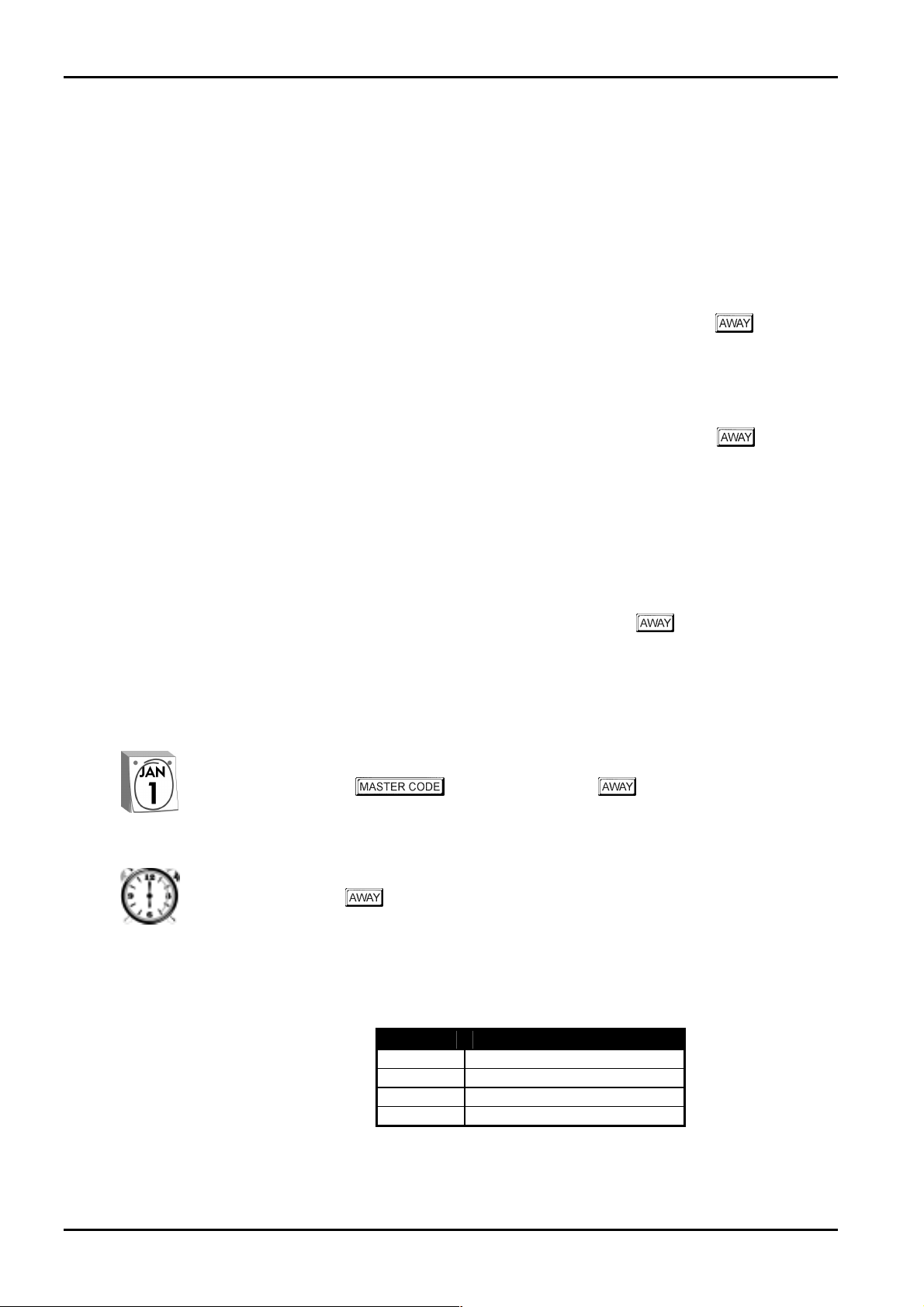
How To Set The New Date and Time
MAINS indicator will remain on as will
1. Enter your followed by 6 and the button.
Three beeps will be heard and the
2. Enter the day, month, year, hour and minute using the (DD, MM, YY, HH, MM)
format.
3. Press the
Two beeps will be heard and the
button when finished.
STAY and AWAY indicators will begin to flash.
STAY and AWAY indicato r s will extinguish.
Zone Defaults
The default zone settings are as listed in the table below.
Zone No Zone Type
1
2 & 3
4 & 5
6
Delay-1
Handover
Instant
24 Hour Zo ne
Table 1: Zone Defaults
ISSUE120.DOC Electronics Design and Manufacturing Pty Limited

This section includes the following;
• Programming
• Programming With The Remote Codepad
Programming
• Programming With The Hand Held Programmer
• Programming With The Programming Key
• Programming Option Bits
• Instal ler’s Programming Commands
• Disable Factory Default
• Defaulting The Control Panel

20
Solution 6+6 Wireless - AE Installation Manual
Programming
The programming options of this control panel are stored in a non-volatile Eprom. This
memory will hold all the relevant configuration and user specific data even during a total
power loss.
The data retention time is as long as ten years without power, therefore, no reprogramming will
be required after powering the control panel down.
The data can be altered as many times as required without the need for any additional
specialised equipment. This memory is laid out in numerous locations, each of which holds the
data for a specific function.
15 is the maximum value that can be programmed into any location.
In general, the entire programming sequence will consist of nominating the location number
required and then entering or altering the data. You will repeat this procedure until all the data
has been programmed to suit your requirements. The factory default settings have been
selected for reporting in the Contact ID Format.
There are two programming modes. The Installer's Programming Mode and the Operators
Programming Mode. Both programming modes have individual access codes and these two
codes must always be programmed differently. The Master Code, as well as being able to arm
and disarm the system gives access to the Operators Programming Mode. The Installers Code
only gives access to the Installer's Programming Mode and does NOT arm and disarm the
system.
Programming of the
any of the following four methods.
Solution 6+6 Wireless - AE control panel can be carried out via
• System Codepad
• Hand Held Programmer (CC814)
• Programming Key (CC891)
• Alarm Link Upload/Download Software (CC816)
ISSUE120.DOC Electronics Design and Manufacturing Pty Limited
Programming 21
Programming With The Remote Codepad
The system must be in the disarmed state with no flashing zone alarm memories, this can be
achieved by entering the
Master Code is
To access the Installer’s Programming Mode, enter the four digit
the
and both the
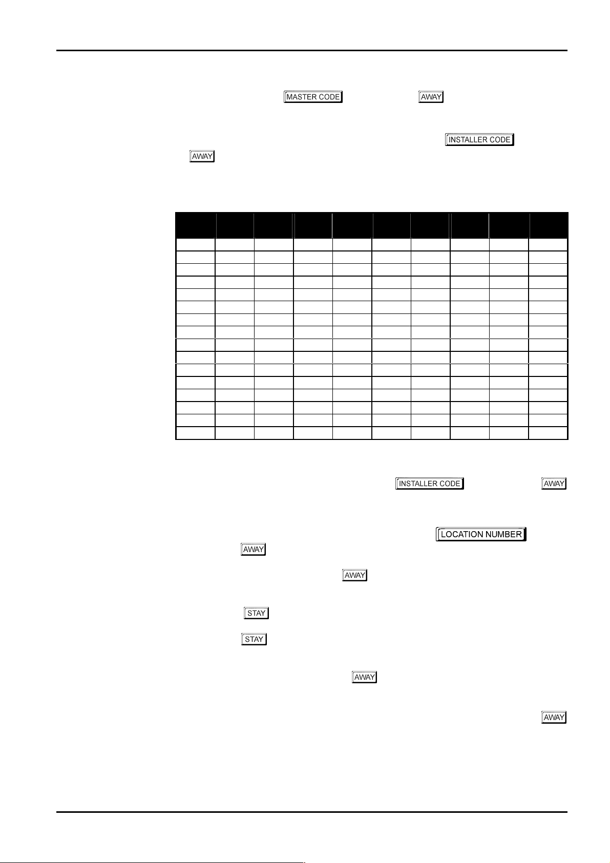
check the system for alarm memory. The codepad indicators will display the current data
stored in the first location (LOCATION 000).
Data
Value
0
1
2
3
4
5
6
7
8
9
10
11
12
13
14
15
2580.
button. The factory default Installer Co de is 1234. Two beeps will be heard
AWAY and the STAY indicators will flash simultaneously. If a long beep is heard,
Zone 1
Indicator
Zone 2
Indicator
Zone 3
Indicator
followed by the button. The factory default
followed by
Zone 4
Indicator
Zone 5
Indicator
Zone 6
Indicator
Zone 7
Indicator
Zone 8
Indicator
MAINS
Indicator
Table 2: Zone Indicators When Programming
Example
To enter Installer’s Programming Mode, enter the followed by the
button. Two beeps will be heard and the codepad will display the current data stored in
“LOCATION 000”.
To move to a particular programming location, enter the
followed by the
To move to the next location, pr ess the
and the data in that location will be displayed via the
If you press the
step back one location. To change data in the current location, enter the new value (0 – 15)
followed by the
positioned at the same location.
To proceed to the next location, press the
displayed.
To exit the Installer’s Programming Mode, enter command
button. Two beeps will be heard and the system will return to the disarmed state. Refer to
“Installer’s Programming Commands” on page 24 for further information on commands that
can be performed during access of the Installer’s Programming Mode.
button. The data of the new location will now be displayed.
button. This will step you to the next location
ZONE indicators.
button without previously entering a location number, the system will
button. This will store the new data into the location and still leave you
button. The next locations data will no w be
960 followed by the
required
Electronics Design and Manufacturing Pty Limited ISSUE120.DOC
22
Solution 6+6 Wireless - AE Installation Manual
Programming With The Hand Held Programmer
The Hand Held Programmer (CC814) has five, seven segment displays. The three on the left
display the location number, and the two on the right display the data for that particular
location.
To connect the hand held programmer, locate the connections marked PROGRAMMING
KEY. This point can be found on the right-hand side of the printed circuit board. Observe the
triangular markings on the printed circuit board and line them up with the markings on the
hand held p rogrammers connecting socket .
When the hand held programmer is correctly connected onto the printed circuit board, one beep
will be heard and four centre bars on the hand held programmer will illuminate with either an
'A' or 'U' suffix to indicate the system is armed or unarmed. Only when the Installer's
Programming Mode has been accessed will any numerals appear on the displa y.
When connecting the hand held programmer to the control panel, make sure that the
switch on the hand held programmer is in the EXT position and that no external
Example
programming key has been connected. Failing to do this may corrupt the control panel's
memory. If this occurs, the control panel will need to be returned to Electronics Design
and Manufacturing Pty Limited where a service fee will be charged to unlock the control
panel's memory.
To enter the Installer's Programming Mode, enter the followed by the #
button. The factory default Installers Code is
hand held programmers display will display the current data stored in " LOCATION 000".
To move to a particular programming location, enter the
1234. Two beeps will be heard and the
# button. The data for the new location will now be displayed.
To move to the next location press the
the data in that location will now be displayed via the codepad indicators.
If you press t he
back one location. To change data in the current location, enter the new value (0 - 15)
followed by the
positioned at the same location.
To proceed to the next location, press the
displayed.
To exit the Installer's Programming Mode, enter command
button. Two beeps will be heard and the system will return to the disarmed state. Refer to
"Installer’s Programming Commands" on page 24 for further information on commands that
can be performed during access of the Installer's Programming Mode.
When using the hand held programmer, any reference in this manual made to the
button should be considered as the
button.
* button without previously entering a loc ation number, the system will step
* button. This will store the ne w data into the location and still leave you
# button. This will step you to the next location and
# button. The next locations data will now be
960 followed by the #
* button and the button considered as the #
followed by the
ISSUE120.DOC Electronics Design and Manufacturing Pty Limited

Programming 23
Programming With The Programming Key
The Programming Key (CC891) is a unique device that will allow you to easily program your
control panel. Inserting the programming key will automatically initiate a data transfer from
the programming key to t h e control p anel memory.
If you have a new p rogra mming key, you sho uld fi rst e nter t he Inst aller 's Pro grammi ng M ode ,
configure the system as required before inserting the programming key.
To connect the programming key, locate the connections marked PROGRAMMING KEY.
This point can be found on the right hand side of the control panel. Observe the triangular
markings on the printed circuit board and line them up with the markings on the programming
key.
To copy the co ntrol panel's data into your new programmi ng key, enter command
followed by the
Programming Key" on page 27 for further infor mation.
Exit the Installer's Programming Mode by entering the command 960 followed by the #
button, wait two seconds for the activity LED to return to its normal state and then remove the
programming key. This programming key will now become your standard data pattern for
future programming of your control panels.
It should be noted that when entering the Installer's Programming Mode, inserting a
programming key and then changing any location would cause a simultaneous update of not
only the programming keys data, but also the control panels data. Therefore, you are not able
to change da ta i n the pr ogra mmi ng ke y wit hou t t he sa me lo ca tion b ein g c hange d i n the co ntro l
panels memory.
Connecting a Programming Key (CC891) to the control panel when the programming
keys memory is blank will corrupt the control panel's memory unless the Installer's
Programming Mode has been entered first. If this occurs, then the control panel will
need to be returned to Electronics Design and Manufacturing Pty Limited where a service
fee will be charged to unlock the control panel's memory.
# button. Refer to "Command 962 - Copy Control Panel Memory To
962
Programming Option Bits
When programming these locations you will notice that there are four alternatives per location.
You may select one, two, three or all of these alternatives for each location, however, only one
number is required to be programmed. This number is calculated by adding the option bit
numbers together.
Example
If at "LOCATION 178" you want options 1, 2 and 4, add the numbers together and the total is
the number to be programmed. In this example, the number to be programmed is 7 (ie. 1 + 2 +
4 = 7).
Option Description
1
2
4
8
Enable Dialler Reporting Functions
Enable Remote Arming Via The Telephone
Enable Upload/Download Via Alarm Link
Terminate “Alarm Link” Session On Alarm
Table 3: Example - Programming Option Bits
Electronics Design and Manufacturing Pty Limited ISSUE120.DOC

24 Solution 6+6 Wireless - AE Installation Manual
Installer’s Programming Commands
There are several commands that can be invoked to perform various functions once the
Installer's Programming Mode has been entered. To invoke the command, enter the
corresponding numerical code followed by the
Command Description
958
959
960
961
962
963
964
965
966
999
Enable/Disable Zone Status Mode When Using Hand Held Programmer
Test Programming Key
Exit Installer’s Programming Mode
Reset Control Panel Back To Factory Default Settings
Copy The Control Panel Memory To The Programming Key
Copy The P rogramming Key Data To The Control Panel
Erase Programming Key
Set Up Domestic Dialling Format
Enable/Disable Automatic Stepping Of Locations During Programming
This Comma nd Displays T he Control P anel’s Softwar e Version N umber
Only When Using The Hand Held Programmer
Table 4: Installer's Programming Command s
# button
ISSUE120.DOC Electronics Design and Manufacturing Pty Limited

Programming 25
Command 958 - Enable/Disable Zone Status Mode
This function enables and disables the zone status display mode. When using the hand held
programmer, the zones will be displayed on the seven-segment display from left to right. If
there is a dash illuminated on the display, the corresponding zone is unsealed and if the display
is blank, the zone is sealed.
The third (or centre) display shows either the number 4 or the number 6. The number 4
constantly illuminated indicates that zones 1 - 4 are being displayed. The number 6 constantly
illuminated indicates that zones 5 and 6 are bein g displayed. T he number 4 flashing indicates
tamper zones 1 – 4 are being displayed. The number 6 flashing indicates tamper zones 5 and 6
are being displayed.
Pressing the
very useful during installation as it allows you to view the status of the zones directly at the
control panel, saving you time and money.
How To Enable Zone Status Mode
1. Enter Installers Programming Mode.
2. Enter co mmand
How To Disable Zone Status Mode
# button will toggle the displa y bet ween the zones. T his feat ure will p rove to b e
1234 followed by the # button).
(ie.
958 followed by the # button.
1. Enter co mmand 958 followed by the # button.
Example
A " - " in the display indicates the zone is unsealed.
A blank display indicates the zone is sealed.
--4-- indicates that zones 1, 2, 3 and 4 are unsealed.
A flashing “4” indicates tamper zones 1, 2, 3 and 4 are sealed.
--6¤¤
¤¤ indicates that tamper zones 1 and 4 are unsealed.
¤¤¤¤
A flashing “6” indicates tamper zones 5 and 6 are unsealed.
Tamper zones report back to base as zones 9, 10, 11, 12, 13 and 14.
Electronics Design and Manufacturing Pty Limited ISSUE120.DOC

26
Solution 6+6 Wireless - AE Installation Manual
Command 959 - Test Programming Key
This command initiates a test to be carried out on the programming key. This test is nondestructive and any data in the programming key will remain intact after the test has been
completed. One long beep indicates that the programming key has failed and three beeps
indicate a successful test. If the programming key has been removed before the test has
completed or the programming key has failed, the data in the programming key has become
corrupt. Remember, do not remove the programming key while the activity LED is
illuminated constantly or pulsing rapidly.
How To Test The Programming Key
1. Enter Installer's Programming Mode.
(ie.
1234 followed by the # button).
2. Plug the pro gramming key onto t he p ins marke d P ROG R A M MI NG KE Y o n the co nt ro l
panel.
3. Enter co mmand
Two beeps will be heard after the programming key has successfully been tested.
4. Enter comma nd
Mode before removing the programming key.
How To Test The Programming Key Using The Hand Held Programmer
1. Before conne cting the hand held pro grammer, make sure that the switch on the hand
held programmer is in the EXT position and that no external key has been plugged onto
the hand held programmer.
2. Enter the Installer's Programming Mode.
(ie.
1234 followed by the # button).
3. Plug the pro gramming key onto the pins marked EXTE RNAL KEY on the hand held
programmer.
4. Enter co mmand
Two beeps will be heard and the programming key connected to the hand held
programmer has now been tested.
5. Enter comma nd
Mode.
6. Leave the switch on the hand held programmer in the EXT position and remove the
external programming key.
959 followed by the # button.
960 followed by the # button to exit the Installer's Programming
959 followed by the # button.
960 followed by the # button to exit the Installer's Programming
Command 960 - Exit Installer's Programming Mode
This command is used to exit the Installer's Programming Mode after you complete your
programming alterations. This is achieved by entering command
button. Two beeps will be heard and the system will return to the disarmed state. This
command can be performed at any programming stage and from any location.
ISSUE120.DOC Electronics Design and Manufacturing Pty Limited
960 followed by the #

Programming 27
Command 961 - Reset Control Panel Back To Factory Default
Settings
This command will reset the control panel back to the factory default values. Refer to the
default values shown throughout this manual or the "Programming Sheets" on page 185. This
is achieved by entering command
heard.
961 followed by the # button. Two beeps will be
Command 962 - Copy Control Panel Memory To Programming Key
This command is used to copy the control panel memory to the programming key.
How To Copy The Control Panel Memory To The Programming Key
1. Enter Installer's Programming Mode.
(ie.
1234 followed by the # button).
2. Plug the pro gramming key onto t he p ins marke d P ROG R A M MI NG KE Y o n the co nt ro l
panel.
3. Enter co mmand
Two beeps will be heard and the control panel's memory has now been copied into the
programming key.
4. Enter command
Mode.
5. Remove the programming key from the control panel.
How To Copy The Panel Memory To Programming Key Using The Hand Held Programmer
1. Before connecting the hand held programmer to the control panel, make sure that the
switch on the hand held programmer is in the EXT position and that no external
programming key has been plugged onto the hand held programmer.
2. Enter Installer's Programming Mode.
(ie.
1234 followed by the # button).
3. Plug the pro gramming key onto the pins marked EXTE RNAL KEY on the hand held
programmer.
4. Enter co mmand
Two beeps will be heard and the control panel's memory has now been copied into the
programming key.
5. Enter command
Mode.
6. Leave the switch on the hand held programmer in the EXT position and remove the
programming key.
962 followed by the # button.
960 followed by the # button to exit Installer's Programming
962 followed by the # button.
960 followed by the # button to exit Installer's Programming
Electronics Design and Manufacturing Pty Limited ISSUE120.DOC

28
Solution 6+6 Wireless - AE Installation Manual
Command 963 - Copy From Programming Key To Control Panel
This command is used to copy data from the programming key to the control panel.
How To Copy The Programming Key Memory To The Control Panel
1. Enter Installer's Programming Mode.
1234 followed by the # button).
(ie.
2. Connect the programming key onto the pins marked PROGRAMMING KEY on the
control panel.
3. Enter co mmand
Two beeps will be heard and the programming key's data has now been copied to the
control panel.
4. Enter command
Mode.
5. Remove the programming key from the control panel.
How To Copy Programming Key Memory To Control Panel Using Hand Held Programmer
1. Before connecting the hand held programmer to the control panel, make sure that the
switch on the hand held programmer is in the EXT position and that no external
programming key has been plugged onto the hand held programmer.
2. Enter Installer's Programming Mode.
(ie.
1234 followed by the # button).
3. Plug the pro gramming key onto the pins marked EXTE RNAL KEY on the hand held
programmer.
4. Enter co mmand
Two beeps will be heard and the programming keys data will now be copied to the
control panel.
5. Enter command
Mode.
6. Leave the switch on the hand held programmer in the EXT position and remove the
programming key.
963 followed by the # button.
960 followed by the # button to exit Installer's Programming
963 followed by the # button.
960 followed by the # button to exit Installer's Programming
ISSUE120.DOC Electronics Design and Manufacturing Pty Limited

Programming 29
Command 964 - Erase Programming Key
This command erases all data from the programming key.
How To Erase The Programming Key
1. Enter Installer's Programming Mode.
(ie.
1234 followed by the # button).
2. Connect the programming key onto the pins marked PROGRAMMING KEY on the
control panel.
3. Enter co mmand
Two beeps will be heard and the programming keys data has now been erased.
4. Enter command
Mode.
5. Remove the programming key from the control panel.
How To Erase The Programming Key Using The Hand Held Programmer
1. Before connecting the hand held programmer to the control panel, make sure that the
switch on the hand held programmer is in the EXT position and that no external
programming key has been plugged onto the hand held programmer.
2. Enter Installer's Programming Mode.
(ie.
1234 followed by the # button).
3. Plug the pro gramming key onto the pins marked EXTE RNAL KEY on the hand held
programmer.
4. Enter co mmand
Two beeps will be heard and the programming keys data has now been erased.
5. Enter command
Mode.
6. Removed the programming key from the hand held programmer.
964 followed by the # button.
960 followed by the # button to exit Installer's Programming
964 followed by the # button.
960 followed by the # button to exit Installer's Programming
Electronics Design and Manufacturing Pty Limited ISSUE120.DOC

30
Solution 6+6 Wireless - AE Installation Manual
Command 965 - Set Up Domestic Dial ling Format
Command 965 has been added to make the set up of the domestic dialling format a one step
operation. Refer to page 85 for more information on Domestic Reporting Format.
After Installer's Programming Mode has been accessed, enter command
the
# button. This will automatically set the following locations in bold below. No other
locations will be changed when command 965 has been issued.
Location Description Setting
LOCATION 49 Handshake Tone 2 (1400 Hz)
LOCATION 50 Transmission Format 11 (Domestic)
LOCATION 052 – 055 Subscriber ID Number 0, 0, 0, 1 (1 Beep)
LOCATION 104 – 108 Zone 1 2, 0, 0, 0, 1 (Delay-1)
LOCATION 109 - 113 Zone 2 1, 0, 0, 0, 1 (Handover)
LOCATION 114 - 118 Zone 3 1, 0, 0, 0, 1 (Handover)
LOCATION 119 - 123 Zone 4 0, 0, 0, 0, 1 (Instant)
LOCATION 124 - 128 Zone 5 0, 0, 0, 0, 1 (Instant)
LOCATION 129 - 133 Zone 6 12, 0, 0, 0, 1 (24 Hour)
LOCATION 134 Report Options 1 0 (Not Used)
LOCATION 135 Report Options 2 3 (Enable Panic/Duress Reports)
LOCATION 136 Report Options 3 0 (Not Used)
965 followed by
Table 5: Command 965 Defau lts
As you can see from the table above, all reporting other than zone alarms have been disabled.
The handshake tone has been set for 1400 Hz tone acknowledgment and the Subscriber ID
Number has been set for one identification beep. The zone reporting has been set so that any
zone that triggers an alarm condition will only report when the alarm occurs, the zone restore
report will not report as there is no separate indications for zone alarm reports and zone alarm
restore reports.
ISSUE120.DOC Electronics Design and Manufacturing Pty Limited
 Loading...