

EDL Displays 6120, 6116, 6119, 6115 Operation And Maintenance Manual
MODEL 6115, 6116, 6119 & 6120
MASTERSYNC COLOR
VIDEO MONITOR
OPERATION AND
MAINTENANCE MANUAL
EDL Displays, Inc.
1300 Research Park Drive
Dayton, Ohio 45432
(937) 429-7423
www.edldisplays.com
REVISED: January 12, 1997

TABLE OF CONTENTS
INTRODUCTION 1
GENERAL INFORMATION 2
VIDEO BANDWIDTH 2
AUTOMATIC SYNC ADAPTATION 2
EASE OF ADJUSTMENT 2
RELIABILITY 2
MODULAR CONSTRUCTION 2
CONFIGURATION CONTROL 3
MAINTAINABILITY 3
LOOP THRU OPERATION 3
SPECIFICATIONS 4
POWER REQUIREMENT 4
DEFLECTION 4
CRT 5
VIDEO 5
USER ADJUSTMENTS 6
PHYSICAL AND ENVIRONMENTAL 7
OTHER FE ATURES 7
WARRANTY 8
MANUAL 8
6115 - 6120 Operation and Maintenance Manual i EDL Displays, Inc. January 1997

INSTALLATION 9
GENERAL 9
UNPACKING 9
AC POWER CONNECTION 9
MECHANICAL INSTALLATION 9
OPTIONAL RACK MOUNT 9
SIGNAL INPUT CONNECTIONS 15
OPERATION 18
CALIBRATION PROCEDURES 1 20
VERTICAL POSITION ADJUSTMENT 20
VERTICAL SIZE ADJUSTMENT 20
HORIZONTAL POSITION ADJUSTMENT 20
HORIZONTAL SIZE ADJUSTMENT 21
TRAPEZOID ADJUSTMENT 21
PINCUSHION ADJUSTMENT 21
CALIBRATION PROCEDURES 2 22
CONTRAST ADJUSTMENT 22
VERTICAL POSITION ADJUSTMENT 22
VERTICAL SIZE ADJUSTMENT 23
HORIZONTAL POSITION ADJUSTMENT 23
HORIZONTAL SIZE ADJUSTMENT 23
HORIZONTAL LINEARITY ADJUSTMENT 23
TRAPEZOID ADJUSTMENT 23
PINCU SHION ADJUSTMENT 24
6115 - 6120 Operation and Maintenance Manual ii EDL Displays, Inc. January 1997

MAINTENANCE, ADJUSTM ENTS AND TROUBLESHOOTING 26
FAULT ISOLATION/TROUBLE SHOOTING 26
MAINTAINABILITY 26
REPLACEABLE ITEMS 26
ORGANIZATIONAL LEVEL TROUBLESHOOTING 27
VIDEO AMPLIFIER BOARD REPLACEMENT 29
DEFLECTION BOARD REPLACEMENT 30
MICROPROCESSOR BOARD REPLACEMENT 31
LOW VOLTAGE POWER SUPPLY REPLACEMENT 32
HIGH VOLTAGE POWER SUPPLY REPLACEMENT 33
HIGH VOLTAGE POWER SUPPLY ALIGNMENT PROCEDURE 34
ANODE AND G2 VOLTAGE ADJUSTMENT PROCEDURE 36
FOCUS VOLTAGE ADJUSTMENT PROCEDURE 37
VIDEO AMPLIFIER ALIGNMENT PROCEDURE 38
CATHODE RAY TUBE REPLACEMENT 41
APPENDIX A 44
LIST OF ACRONYMS 44
LIST OF ILLUSTRATIONS
FIGURE 1: MODEL 6115 & 6116 OUTLINE DRAWING ...............................................................................................10
FIGURE 2: MODEL 6119-8 OUTLINE DRAWING...............................................................................................................11
FIGURE 3: MODEL 6119 OUTLINE DRAWING ..............................................................................................................12
FIGURE 4 MODEL 6120 OUTLINE DRAWING........................................................................................................................13
FIGURE 5: 110/220 SWITCH LOCATION..............................................................................................................................14
FIGURE 6: 6120 REARPANEL SIGNAL INPUT CONNECTIONS.............................................................................................17
FIGURE 7: CALIBRATION 1 FLOW CHART....................................................................................................................25
FIGURE 8: ORGANIZATIONAL LEVEL TROUBLESHOOTING FLOW CHART....................................................28
LIST OF TABLES
TABLE 1: CONTROL FUNCTIONS IN OPERATIONAL AND CALIBRATE MODE ....................................................19
TABLE 2: LIST OF ORGANIZATIONAL LEVEL REPLACEABLE ITEMS.....................................................................27
6115 - 6120 Operation and Maintenance Manual iii EDL Displays, Inc. January 1997

INTRODUCTION
This technical manual contains operation and maintenance instructions
for the EDL Model 6115, 6116, 6119 and 6120 MasterSync Video
Monitors. These models are high quality, high performance, high
resolution color monitors. They are unique in their ability to automatically
synchronize and display virtually any video format. This feature makes it
very useful as a communications monitor when integrated with a video
switch system as well as Windows applications.
This manual should be carefully reviewed before attempting operation.
A thorough understanding of the control functions is required for proper
set up and operation of the monitors.
To achieve the best results from these models please follow the
procedures in the order given below:
1. Review the Operation and Maintenance Manual.
2. Determine the operating system format and the system signal input
cabling required. Follow the guide in this manual when attaching
system input cabling.
3. If customized calibration is required, follow the calibration
procedures in this manual.
When corresponding with EDL Displays relative to this equipment,
please include the model number and serial number of the monitor in
question.
6115 - 6120 Operation and Maintenance Manual 1 EDL Displays, Inc. January 1997

GENERAL INFORMATION
VERY HIGH RESOLUTION
EDL Displays Color Monitors have the highest resolutions available. The dynamically
focused 0.28mm dot pitch (0.25 for Model 6120)cathode ray tubes provide the
sharpest images available with resolutions up to and including 1600 x 1280 for 6119 &
6120 (1280 x 1024 for Models 6115 and 6116).
VIDEO BANDWIDTH
The video bandwidth of 140MHz supports resolutions up to 1600 x 1280 @ 60 Hz NI.
AUTOMATIC SYNC ADAPTATION
These monitors will automatically sync and display any RGB video format within its
operating frequency range. It will automatically accommodate five (5), four (4) and
three (3) cable signal formats in that order of priority.
EASE OF ADJUSTMENT
All controls that may be necessary to adjust in the field are acces sible either at the
front or rear panel.
RELIABILITY
The monitor is designed with reliability as paramount in importance. Reliability is
accomplished by using high quality parts and assuring that these parts are operating
at less than their intended stress levels. All devices which must dissipate heat are
mounted on the rear panel heat sinks. This allows for convection cooling of the
monitor eliminating the need for potentially unreliable fans.
MODULAR CONSTRUCTION
The monitor is constructed around a card cage configuration. All circuitry is in the
form of plug-in modules which plug into the rear panel of the unit.
6115 - 6120 Operation and Maintenance Manual 2 EDL Displays, Inc. January 1997

CONFIGURATION CONTROL
Any changes to the monitor design are form, fit, and function to previous revisions.
The replaceable modules in the units delivered today are backward compatible into the
first EDL Displays product shipped in January 1990.
MAINTAINABILITY
All circuitry within the monitor is contained in functional replaceable modules such as
deflection output, microprocessor control, video amplifiers (3), and power supplies. A
defective module can be detected by simple tests and the monitor can be repaired by
replacing the module. This may eliminate the need for a field service representative or
shipment of the monitor back to the factory.
An important benefit of these plug-in replaceable modules is the very short MeanTime-To-Repair (MTTR).
Since the replaceable modules are the same as used in other EDL Displays products,
sparing and personnel training are greatly simplified.
LOOP THRU OPERATION
Loop thru operation is provided by a HI-LO impedance switc h selection. This allows
the use of the monitor with other devices on the output of the raster engine or video
switch.
6115 - 6120 Operation and Maintenance Manual 3 EDL Displays, Inc. January 1997

SPECIFICATIONS
EDL MODEL 6115, 6116, 6119 & 6120
MASTERSYNC MONITOR SPECIFICATIONS
DEFLECTION
SCAN RATE RANGES: Horizontal scan rates from 15 to 90 kHz, 40 to 120 Hz non-
interlaced and 20-60 Hz interlaced vertical. Automatic selection to match input video
format.
RETRACE TIME: Maximum of 3.0 microseconds horizontal and 400 microseconds
vertical.
HORIZONTAL AND VERTICAL SYNC: Automatic detection and selection of
composite (3 wire), separate video and mixed sync (4 wire), and separate video, vertical
and horizontal sync (5 wire). Polarity: Negative only for three wire operation. Positive or
negative for four and five wire operation. Separate sync inputs are ECL and TTL
compatible 1.0 to 4.0 volts peak to peak.
LINEARITY: Horizontal and vertical nonlinearity (when measured using the EIA Standard
Ball Chart Method or equivalent) is better than +1% raster height.
RASTER SIZE REGULATION: Raster size change caused by changes in CRT beam
current from 0-100% APL (approximately 0 to 200 Microamps) will be less than 0.5%.
GEOMETRIC DISTORTION: No point on the raster (i.e., pixel) is displaced from its
proper position by more than 1% of raster height within a 9 inch circle (Model 6115 &
6116) and within an 11 inch circle (Model 6119 & 6120) and no more than 1.5%
elsewhere.
MISCONVERGENCE: Within a centrally located circle of six inch diameter
misconvergence will be less than 0.2mm and elsewhere will be less than 0.4mm when
measured as the worse case between any two colors.
POWER REQUIREMENT
A.C. POWER: Input voltage 90-132 v.a.c. or 180-264 v.a.c. switch selectable inside the
monitor, 47 to 63 Hz. Power Consumption 150 Watts ma ximum.
6115 - 6120 Operation and Maintenance Manual 4 EDL Displays, Inc. January 1997

CRT
SCREEN SIZE AND TYPE: (Model 6115 & Model 6116) 16 inch diagonal, 0.28mm
shadow mask, precision inline DAF gun (PIL), burst protection, inner magnetic shield, 90
degree deflection type tube with a P22 short persistence dot type black matrix phosphor.
Fifty-two percent (52%) transmissivity anti-glare panel standard.
(Model 6119) 19-inch diagonal, 0.32mm shadow mask, precision inline gun (PIL), burst
protection, inner magnetic shield, 90 degree deflection type tube with a P22 short
persistence dot type black matrix phosphor. Forty one percent (41%) transmissivity anti-
glare panel standard.
(Models 6119-7 & 6119-8) 19-inch diagonal, 0.28mm shadow mask, precision inline DAF
gun (PIL), burst protection, inner magnetic shield, 90 degree deflection type tube with a
P22 short persistence dot type black matrix phosphor. Fifty-two percent (52%)
transmissivity anti-glare panel standard.
(Model 6120) 21-inch 20-inch viewable diagonal, 0.25mm shadow mask, DAF gun, burst
protection, inner magnetic shield, 90 degree deflection with P22 short persistence dot
type black matrix phosphor. The shadow mask in Advanced Invar. The 52%
transmissivity anti-glare filter is integral to the flat-square screen.
WARM UP TIME : A maximum of 5 minutes for the monitor to meet the specifications
contained herein.
RESOLUTION AND DISPLAY SIZE: Models 6115 & 6116 have 1280H X 1024V
resolution with a maximum display area of 12.8" (32.5 cm) wide by 9.6" (24.4 cm) high.
Models 6119-7 & 6119-8 has 1600H X 1280V resolution with a maximum display area of
15.7" (39.9 cm) wide by 11.7" (29.6 cm) high. Model 6119 has 1280 X 1024 resolution
with a maximum display area of 15.7" (39.9 cm) wide by 11.7" (29.6 cm) high. The Model
6120 has 1600 X 1280 resolution with a maximum display area of 16.0” (406.4mm.) wide
by 12.0” (304.8mm.) high.
VIDEO
BRIGHTNESS: Nominal 35 foot-Lamberts.
COLORIMETRY: D9300 white-adjustable to other standards.
FREQUENCY AND PULSE RESPONSE (20 fL):
Bandwidth @ -3.0 dB; 1.0Hz to 140 MHz
Flatness @ +0.5 dB; 10HZ to 120 MHz
Rise/Fall Time: 3.0 nsec
SIGNAL INPUT IMPEDANCE:
Resistance @ Low-Z: 75 OHM + 5%
Resistance @ High-Z: > 20k OHM
Capacitance: 8 pF (nominal) @ 2 MHz
6115 - 6120 Operation and Maintenance Manual 5 EDL Displays, Inc. January 1997

SIGNAL INPUT LEVEL (AC COUPLED):
Composite: 1.0 Vp-p Nominal (0.7 - 1.4 Vp-p)
Non-Composite: 0.7 Vp-p Nominal (0.5 - 1.0 Vp-p)
SYNC SIGNAL (COMPOSITE ON GREEN):
Back Porch: 1.2 uSec minimum
Level: 0.3 Vp-p Nominal (0.2-0.4 Vp-p)
Width: 1.0 uSec Nominal (0.5-3.0 uSec)
Polarity: Negative
SYNC INPUT:
Separate or mixed: 1.0 V to 4.0 V p-p nominal positive or negative polarity.
SYNC TIMING REQUIREMENT:
HORIZONTAL
Sync Pulse > 1.0 u s
Back Porch > 1.2 u s
Front Porch > 0
VERTICAL
Sync Pulse > 25 u s
Back Porch > 375 u s
Front Porch > 0
DC OUTPUT RESTORER (BLANKING):
Stability Black level within 1% of peak luminance at any
APL from 10% to 90%.
Range: +55 V to +6 5 V (Adjustable)
INPUT CONNECTIONS: Coaxial BNC with selectable 75 OHM or high impedance
termination.
USER ADJUSTMENTS
EXTERNAL: RGB Video - Gain and black level.
CALIBRATION MODE: Front panel adjustment for all minor alignment needs including:
vertical position, vertical size, horizontal position, horizontal size, trapezoid, and
pincushion for a minimum of twenty one different video formats.
6115 - 6120 Operation and Maintenance Manual 6 EDL Displays, Inc. January 1997

PHYSICAL AND ENVIRONMENTAL
MECHANICAL: Rugged steel chassis construction with rear panel accessible
functional modules. Like modules interchangeable unit to unit.
TEMPERATURE: 0 to 50 degrees centigrade operating; -40 to +85 degrees centigrade
non-operating.
HUMIDITY: 5 - 95 percent non-condensing.
ALTITUDE: 3000 meters (10,000 ft) operating and 13,000 meters (30,000 ft) non-
operating.
DIMENSIONS: Model 6115/6116: 15.38" (39.07 cm) wide by 14" (35.57 cm) high by
17.75" (45.09 cm) deep.
Model 6119: Overall when mounted in plastic enclosure 18.5" (46.99 cm) wide by 16.4"
(44.66 cm) high by 21.6" (54.86 cm) deep.
Model 6119-8 Rack Mount: Overall 19" (48.26 cm) wide by 15.75" (40.01 cm) high by
21.5" (54.61 cm) deep.
Model 6120: Overall 19.3” wide by 15.5” high by 19.1” deep.
WEIGHT: Model 6115/6116: 58 lbs (26 Kg). Model 6119 83 lbs (37 Kgs)
Model 6120 62 lbs (28.2 Kgs.).
CAUTION! These monitors are awkward and require two people for safe handling.
OTHER FEATURES
MASTER SYNC: Automatic detection and alignment to a maximum of twenty-one
different video formats. The video formats may have totally different timing
specifications.
DEGAUSS: Automatic deGauss at power on with manual deGauss switch provided on
front; minimum time between deGauss operations is ten minutes.
SWEEP FAILURE DETECTION: High voltage disabled with either horizontal or vertical
sweep loss.
CONTROLS: Power on/off, contrast/calibration, brightness and DeGauss/Mode
provided on front of the monitor.
6115 - 6120 Operation and Maintenance Manual 7 EDL Displays, Inc. January 1997

WARRANTY
One year parts and labor at EDL Displays, Inc.
MANUAL
One copy supplied with each unit which includes:
Installation
Operation
Maintenance
6115 - 6120 Operation and Maintenance Manual 8 EDL Displays, Inc. January 1997

INSTALLATION
GENERAL
This section describes the installation of the monitor. The monitor is pre-aligned at the
factory to user input requirements. However, there may still be the need for some minor
adjustments to be made. Those procedures will be provided later in the Calibration
Procedures section.
UNPACKING
Before unpacking, the carton should be inspected for shipping damage. The carton
should be carefully opened and the monitor removed. The monitor should then be
carefully inspected for shipping damage. If damage has occurred, the shipping carton
and all packing materials should be saved for possible inspection by the shipping
company. The shipping company and EDL Displays should be notified at this time.
AC POWER CONNECTION
Before connecting the monitor, determine what a.c. power is to be used and make sure
that the monitor is configured properly for that voltage. NOTE: The power setting upon
shipment is 110 volts unless otherwise requested by the customer. The voltage of the
monitor may be changed at the power supply module accessible from the rear of the unit.
The power supply must be removed for access to the voltage select switch (see figure
4).
MECHANICAL INSTALLATION
The 6119 monitor is designed to be mounted and secured in place on any flat surface by
four 10-32 X 1/2 inch screws into the bottom panel. See figure 3 for the hole pattern
required. (Model 6119 only)
OPTIONAL RACK MOUNT
As an option, the Model 6119-8 is provided with an all steel chassis and bezel assembly.
This option includes heavy duty slides and requires only 15.75 inches of panel space.
6115 - 6120 Operation and Maintenance Manual 9 EDL Displays, Inc. January 1997
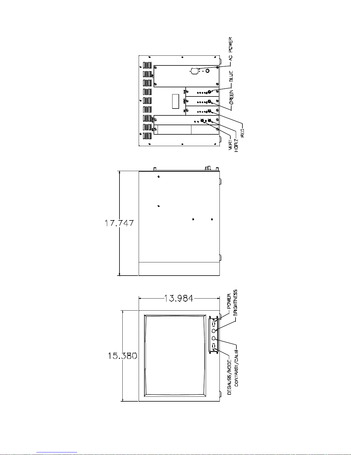
Figure 1: MODEL 6115 & 6116 OUTLINE DRAWING
6115 - 6120 Operation and Maintenance Manual 10 EDL Displays, Inc. January 1997
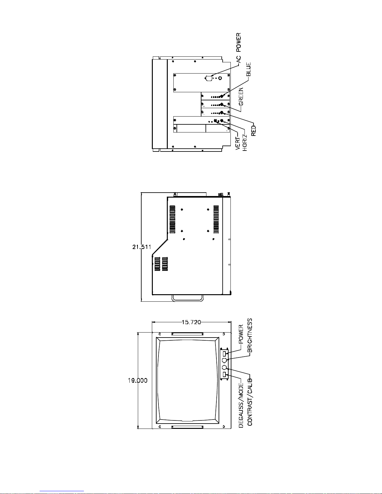
Figure 2: MODEL 6119-8 OUTLINE DRAWING
6115 - 6120 Operation and Maintenance Manual 11 EDL Displays, Inc. January 1997
 Loading...