

EDL Displays 3023 Installation And Operation Manual

3023
EDL Displays, Inc.
Installation and Operation
Manual
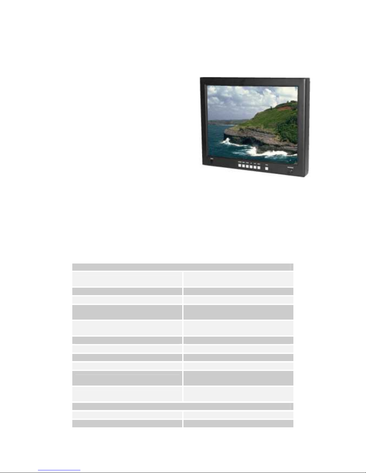
Model 3023
LCD Video Monitor
Revised February 20, 2006
www.edldisplays.com

Table of Contents
INTRODUCTION 3
FEATURES 3
SPECIFICATIONS 3
INSTALLATION 5
GENERAL 5
UNPACKING 5
MECHANICAL INSTALLATION 5
SIGNAL INPUT CONNECTIONS 6
GRAPHICAL USER INTERFACE AND ON-SCREEN DISPLAY 11
Main Menu 12
PICTURE Submenu 12
OSD Submenu 13
UTILITY Submenu 13
Quick Menu 13
RECOMMENDED USE 15
Safety Precautions and Maintenance 15
Table of Figures
FIGURE 1 MODEL 3023 OUTLINE DRAWING 9
FIGURE 2 REAR PANEL INPUT CONNECTIONS 10
FIGURE 3 IR REMOTE 11
3023 Operation and Maintenance Manual EDL Displays, Inc. February, 2006
2
Introduction
Features
• 23.1" diagonal LCD (equivalent to 25" CRT)
• Rugged design intended for harsh environments
• Metal Enclosure with VESA mount, Rack mount,
Console mount or Tabletop
• Auto-detection of multiple display formats from
640x480 to 1600x1280, including interlaced
formats, with excellent scaling to 1600x1200
native resolution
• VESA DPMS compliant, VESA DDC1/2 plug
and play compliant
• Full-range backlight dimming standard
• Backlight stabilization standard
• Accepts digital or analog RGB at DVI-I connector, S-video or composite video at DIN or RCA
connector
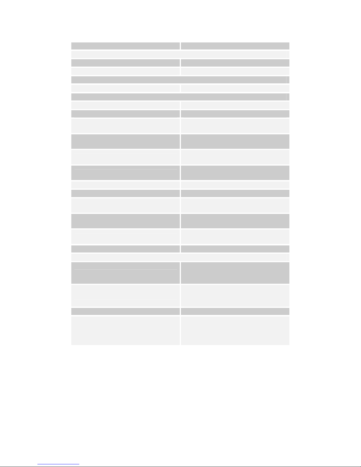
Specifications
Display
Active area
Native resolution 1600 x 1200
Pixel pitch 0.29mm (0.098 X RGB)
Colors
Contrast ratio
Luminance 250 cd/m² (typical, at 25°C)
Luminance variation 25% (max, at 25°C)
Viewing angle, H ± 80° (typical, for CR ≥ 10)
Viewing angle, V ± 80° (typical, for CR ≥ 10)
CIE white
Response time
Backlight
Type 6 CCFL
Lifetime 50,000 hrs
470.4mm x 352.8mm (18.5" x
13.9")
16,777,216
(256 gray levels)
400:1
(typical, at 25°C)
X = 0.313, Y = 0.329
(typical, at 25°C)
tr = 15msec, tf = 10msec
(typical, at 25°C)
3023 Operation and Maintenance Manual EDL Displays, Inc. February, 2006
3
(typical, at 25°C)
Electromagnetic Environment
Susceptibility Per EN55022
Emissions Per EN55022, FCC class A
Safety
Design Per UL/C 1950, EN60950
Physical Environment
Temperature (operating) 0°C to +50°C
Temperature (storage) -20°C to +60°C
Relative Humidity (operating)
Relative Humidity (storage)
Altitude (operating)
Altitude (storage)
Shock (operating) 30g, 11msec ½ sine
Shock (storage) 30g, 11msec ½ sine
Weight (in standard
configuration)
Power (in standard
configuration)
Vibration (operating)
Vibration (storage) TBD
Video signal input
Sync signal input
Sync selection Automatic
Signal connector
90%, condensing
(to 50°C)
90%, condensing
(to 60°C)
Sea level to 15,000ft
(4500m)
Sea level to 40,000ft
(12000m)
36lbs. (16.3Kg)
95W
±1mm, 2 to 13Hz; 0.7g, 13 to
100Hz, 3 axes
Inputs
RGB digital (TMDS) or RGB
analog, 0.7V
or composite video
Separate TTL H&V, Composite TTL
H&V,
Sync on green
DVI-I for RGB, DIN for S-video,
RCA jack for composite video
(RGB via HD-15 or BNC handled
with cable options)
into 75Ω, S-video
p-p
3023 Operation and Maintenance Manual EDL Displays, Inc. February, 2006
4

INSTALLATION
GENERAL
This section describes the installation of the monitor. The monitor is pre-aligned at
the factory to user input requirements. However, there may still be the need for
some minor adjustments to be made. Those procedures will be provided later in the
Calibration Procedures section.
UNPACKING
Before unpacking, the carton should be inspected for shipping damage. The carton
should be carefully opened and the monitor removed. The monitor should then be
carefully inspected for shipping damage. If damage has occurred, the shipping
carton and all packing materials should be saved for possible inspection by the
shipping company. The shipping company and EDL Displays should be notified at
this time.
MECHANICAL INSTALLATION
The 3023 monitor is designed to be mounted and secured in place on any flat
surface.
3023 Operation and Maintenance Manual EDL Displays, Inc. February, 2006
5
SIGNAL INPUT CONNECTIONS
The Model 3023 LCD Monitor accepts both digital and analog video signals at its
integrated connector (DVI-I).
When connecting the monitor to a digital signal source, it is necessary to use a cable
that terminates on the monitor end with a DVI-I connector that mates to the monitor’s
connector, and on the source end with a DVI connector appropriate to the source –
usually a DVI-D connector. (See cable descriptions below for details.)
When connecting the monitor to an analog signal source, it is necessary to use a cable
that terminates on the monitor end with a DVI-I connector that mates to the monitor’s
connector, and on the source end with an HD-15 connector or with some combination of
three to five BNC connectors, as appropriate to the source. (See cable descriptions
below for details.)
Provided the correct cable is used, the monitor will automatically sense adapt to any
analog or digital signals applied. In the case of analog signals, the monitor will
automatically sense and adapt to the sync type (sync-on-green, composite separate
sync, or separate horizontal and vertical syncs).
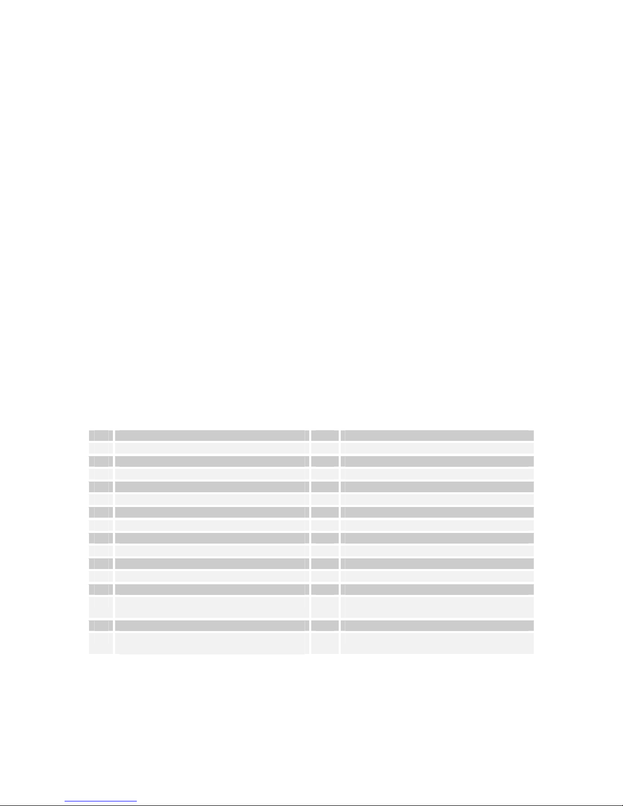
Video Input Connector Pin Assignments
Pin Signal Pin Signal
1 TMDS Data 2 - 16 Hot Plug Detect
2 TMDS Data 2 + 17 TMDS Data 0 3 TMDS Data 2/4 Shield 18 TMDS Data 0 +
4 TMDS Data 4 - 19 TMDS Data 0/5 Shield
5 TMDS Data 4 + 20 TMDS Data 5 6 DDC Clock 21 TMDS Data 5 +
7 DDC Data 22 TMDS Clock Shield
8 Analog Vertical Sync 23 TMDS Clock +
9 TMDS Data 1 - 24 TMDS Clock 10 TMDS Data 1 + C1 Analog Red
11 TMDS Data 1/3 Shield C2 Analog Green
12 TMDS Data 3 - C3 Analog Blue
13 TMDS Data 3 + C4 Analog Horizontal Sync (or composite H & V
sync)
14 +5VDC (power input) C5 Analog Ground (RGB return)
15 Ground (5VDC, and analog H and V sync
return)
3023 Operation and Maintenance Manual EDL Displays, Inc. February, 2006
6
 Loading...