

EDL Displays 3018, 3019 User Manual
EDL Displays, Inc.
1300 Research Park Drive
Dayton, Ohio 45432
(937) 429-7423
www.edldisplays.com
Part Number: 3018-19-MAN-LCD, rev. 2, April 10, 2003
EDL Displays 3000 Series LCD Monitors
Notice to Users
The equipment described in this manual uses and generates radio frequency energy and can cause
interference to other equipment if not installed and used in accordance with guidelines set forth here. This
equipment is designed to meet requirements for Class B computing devices set forth in FCC Rules, Part
15, Subpart J, and requirements of the European Union for electromagnetic compatibility of equipment to
be used in residential and light industrial environments (Directive 89/336/EEC, EN50081-1, EN50082-1).
When used as recommended, radio frequency emissions from this equipment will fall within acceptable
limits for residential and light industrial environments. Operation of this equipment in other environments
could subject it to interference from other equipment.
This manual provides guidelines for the safe and effective use of the equipment described. However, EDL
Displays, Inc. makes no warranty concerning the suitability of this equipment for any particular use and
explicitly disclaims any responsibility or liability for loss or damage that might result from its improper
application. Knowledge of good practice as it relates to display devices and solid state electronics in
general is necessary for the proper application of these guidelines, and this manual assumes such
knowledge on the part of the reader.
EDL Displays, Inc. has made every effort to ensure that information presented in this manual is complete
and accurate. However, EDL Displays, Inc. cautions that this information often relates, of necessity, to a
typical or exemplary situation. EDL Displays, Inc. explicitly disclaims any responsibility or liability for
any loss or damage that might result from the use of this information in particular situations. EDL reserves
the right to make changes to this manual at any time without obligation to provide notification of such
changes.
This manual is distributed under copyright. It may not be reproduced for commercial purposes, in whole
or on part, without the written permission of EDL Displays, Inc.
Limited Warranty
EDL Displays, Inc. (hereinafter “EDL”) warrants that the products described herein will remain free from
defects in material and workmanship for a period of two years from the date of delivery. EDL will, at its
own expense, correct any such defect that might manifest itself and be properly reported during this period.
EDL’s corrective action shall be limited to repair of the defect, or, at its discretion, replacement of the
defective unit. In order to obtain the benefits of this warranty, it shall be the purchaser’s obligation to
obtain prior authorization (in the form of an RMA number) from EDL for return of the product, and to
provide for shipment of the product both to and from EDL’s repair facility. This warranty does not extend
to damage caused by mishandling during shipping or to damage caused by misapplication or abuse
(whether intentional or accidental) of the product or failure to follow EDL’s guidelines. This warranty is
offered in lieu of any warranty concerning the suitability or fitness of this product for a particular
application and is extended only to the original purchaser.
The symbol at left, together with the word “warning,” is used throughout this
manual to call special attention to information that is intended to help the user
avoid personal injury and/or damage to equipment.
The symbol at left, together with the word “note,” is used throughout this
manual to call attention to supplementary information that might be of special
interest or value to the user.
Copyright © 2002 -ii- by EDL Displays, Inc.

User’s Manual
Table of Contents
INTRODUCTION................................................................................................................... 1
F
EATURES OF
C
ONFIGURATION GUIDE
INSTALLATION.................................................................................................................... 3
U
NPACKING
C
HECKING PACKAGE CONTENTS
M
OUNTING
Rack Mounting .................................................................................................................. 3
Console or Panel Mounting .............................................................................................. 4
VESA Arm or Yoke Mounting ........................................................................................... 5
M
AKING VIDEO INPUT CONNECTIONS
M
AKING POWER AND GROUND CONNECTIONS
AC Power .......................................................................................................................... 6
DC Power.......................................................................................................................... 7
OPERATION .......................................................................................................................... 8
EDL 3018
AND
3019 LCD M
ONITORS
............................................................ 1
......................................................................................................... 1
........................................................................................................................... 3
............................................................................................ 3
............................................................................................................................. 3
................................................................................... 6
...................................................................... 6
G
ETTING FAMILIAR WITH THE OPERATOR CONTROLS AND INDICATORS
S
ETTING UP THE VIDEO SOURCE
U
SING THE ON-SCREEN DISPLAY
N
AVIGATING THE ON-SCREEN MENU SYSTEM IN DETAIL
............................................................................................ 9
(OSD)
TO ADJUST THE MONITOR
................................................... 12
.............................. 8
.................................... 11
Main Menu ...................................................................................................................... 12
Picture Submenu ............................................................................................................. 13
OSD Submenu ................................................................................................................. 14
Utility Submenu............................................................................................................... 15
Quick Menu..................................................................................................................... 16
MAINTENANCE AND SERVICE ..................................................................................... 17
R
OUTINE MAINTENANCE
T
ROUBLE-SHOOTING
L
INE FUSE REPLACEMENT
B
ACKLIGHT REPLACEMENT
S
ERVICE AND SUPPORT
..................................................................................................... 17
............................................................................................................ 17
................................................................................................... 18
.................................................................................................. 19
........................................................................................................ 19
APPENDIX A: VIDEO INPUT CONNECTOR PIN ASSIGNMENTS .......................... 20
APPENDIX B: VIDEO CABLE OPTIONS ....................................................................... 21
HD-15
HD-15
TO
HD-15 ................................................................................................................ 21
TO
5 BNC ................................................................................................................ 21
APPENDIX C: TOUCHSCREEN SERIAL INTERFACE .............................................. 22
APPENDIX D: X-TERMINAL OPTION........................................................................... 23
I
NSTALLATION
R
ECOMMENDATIONS FOR SETUP OF THE X-TERMINAL
..................................................................................................................... 23
Copyright 2002 -iii- by EDL Displays, Inc.
......................................................... 24

EDL Displays 3000 Series LCD Monitors
APPENDIX E: IR REMOTE CONTROL OPTION......................................................... 25
APPENDIX F: OUTLINE AND MOUNTING DRAWINGS........................................... 26
APPENDIX G: TECHNICAL SPECIFICATIONS .......................................................... 30
M
ODEL
3018........................................................................................................................ 30
M
ODEL
3019........................................................................................................................ 31
Table of Figures
Figure 1 -- Rear view of 3018/19 showing connectors............................................................. 6
Figure 2 – 3018/19 front view, showing operator controls....................................................... 8
Figure 3 – OSD Controls ........................................................................................................ 12
Figure 4 -- 3018/19 I/O panel showing fuse location ............................................................. 18
Figure 5 – Rear View 3018/3019 with X-terminal ................................................................. 23
Figure 6 – Optional Hand-held control unit............................................................................ 25
Figure 7 – Model 3018RM Outline Drawing (shown with X-terminal option) ..................... 26
Figure 8: 3018 Outline Drawing............................................................................................. 27
Figure 9: 3019RM Outline Drawing....................................................................................... 28
Figure 10: 3019 Outline Drawing........................................................................................... 29
Copyright © 2002 -iv- by EDL Displays, Inc.
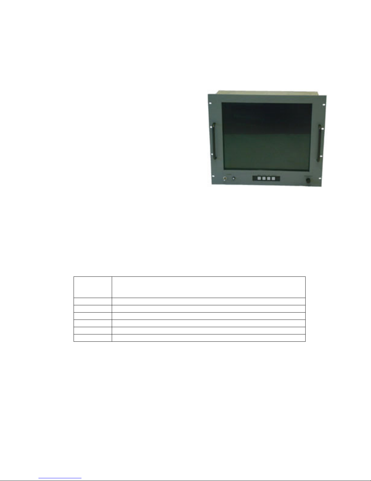
INTRODUCTION
FEATURES OF EDL 3018 AND 3019 LCD MONITORS
• Screen diagonals of 18.1” and 19.0”
• High performance video controller/scaler
common to all models.
• Full-range backlight dimming standard on
all models
• Luminance stabilization circuit standard
on all models
• Rugged enclosures suitable for rack,
console panel, VESA arm or yoke
mounting
• Options include touchscreens, DC power,
more
User’s Manual
CONFIGURATION GUIDE
A 3000 series monitor is specified using the model numbering scheme illustrated in the table
below. The full model number consists of a base model number followed by a series of
designators indicating options installed.
Base
Model
Number
3018CM 18.1” LCD monitor, 1280x1024, console/panel mount package
3018RM 18.1” LCD monitor, 1280x1024, rack mount package
3018VM 18.1” LCD monitor, 1280x1024, VESA arm or yoke mount package
3019CM 19.0” LCD Monitor, 1280x1024, console/panel mount package
3019RM 19.0” LCD Monitor, 1280x1024, rack mount package
3019VM 19.0” LCD Monitor, 1280x1024, VESA arm or yoke mount package
Description
Copyright 2002 -1- by EDL Displays, Inc.
EDL Displays 3000 Series LCD Monitors
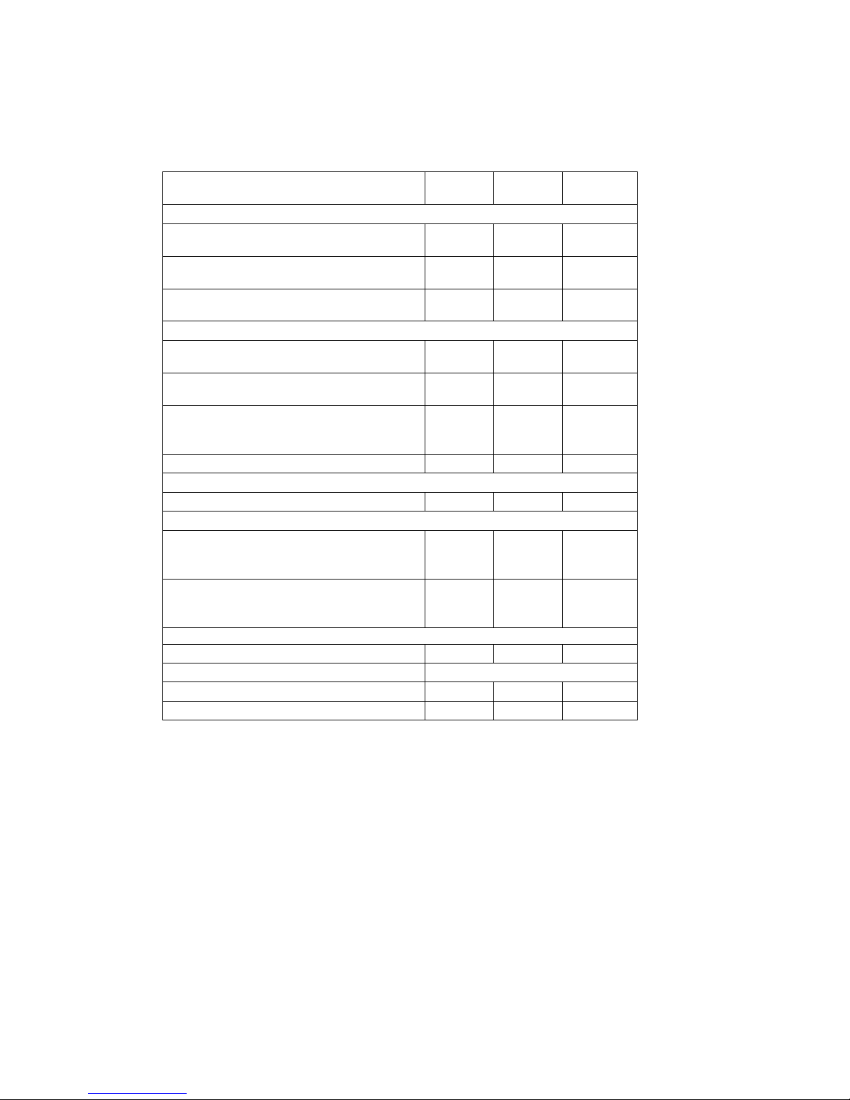
Options available for the 3000 series monitors are described in the table below.
3018CM
3019CM
Power Supply Options
115 to 230VAC Input (85 to 264VAC, 47
to 66Hz and 400Hz), IEC receptacle
115 to 230VAC Input (85 to 264VAC, 47
to 66Hz and 400Hz), military receptacle
24VDC Input (-18VDC to +32VDC),
screw terminal block
Screen Overlay Options
Strengthened glass, A-R coating,
unbonded
Strengthened glass, fine etch,
unbonded
Capacitive touchscreen, A-R etch, 88%
transmissivity, unbonded, with serial
controller
Bonding of overlay to LCD panel Opt Opt Opt
Optional Add-on Modules
X-terminal Opt Opt Opt
Operator Controls Options
Front controls, including digital controls
for OSD, analog luminance control and
power switch
Front controls, including digital controls
for OSD, analog luminance control, but
no power switch
Remote control option
IR remote controls for OSD Opt Opt Opt
Video cable options
HD-15 to HD-15, 2m Opt Opt Opt
HD-15 to 5 BNC, 2m Opt Opt Opt
Std Std Std
Opt Opt Opt
Opt Opt Opt
Std Std Std
Opt Opt Opt
Opt Opt Opt
Std Std Std
Opt Opt Opt
3018RM
3019RM
3018VM
3019VM
Copyright © 2002 -2- by EDL Displays, Inc.

User’s Manual
INSTALLATION
This section describes the unpacking and installation of the monitor.
UNPACKING
Before unpacking, the shipping carton should be inspected for damage. Then, the carton
should be carefully opened and the monitor removed. The monitor itself should be carefully
inspected for shipping damage. If damage has occurred, the shipping carton and all packing
materials should be saved for possible inspection by the shipping company, and the shipping
company and EDL Displays should be notified immediately.
NOTE: EDL recommends saving the packaging for re-use in case the
monitor should ever have to be shipped to a new location.
CHECKING PACKAGE CONTENTS
All EDL monitors are supplied with a User’s Manual and with cables and other optional
accessories as specified by the customer at the time of order. The contents of the package
should be checked against the packing list to ensure that all items are present.
MOUNTING
Rack Mounting
The 30xx-RM monitors are designed to be mounted without slides in an EIA 19” rack
cabinet. The hole pattern on the monitor’s front panel allows mounting the unit on rack rails
that have either a “Wide” or a “Universal” hole pattern.
NOTE: About “Universal” vs. “Wide” hole spacings on EIA rack
cabinet rails.
The mounting rails that run vertically along the inside edges of the front
and rear openings of EIA rack cabinets can be of two types. “Wide” rails
have holes spaced 0.5” and 1.25” on centers, in a repeating pattern.
These rails are prevalent in Europe. “Universal” rails have holes spaced
0.5” 0.625” and 0.625” on centers, in a repeating pattern. Thus the
“Universal” rails have a hole pattern that contains the “Wide” pattern but
provides an additional hole at the midpoint of the pattern. “Universal”
rails are most prevalent in the U.S.
Before installing the monitor in a rack, ensure that the following conditions for installation
are met:
Copyright 2002 -3- by EDL Displays, Inc.

EDL Displays 3000 Series LCD Monitors
• Adequate ventilation must be available within the rack cabinet to ensure that monitor
is not exposed to ambient temperatures above 50°C.
• The relative humidity of the air within and around the rack cabinet should not exceed
85%.
• Following installation, there must be sufficient clearance around the ventilation holes
in the monitor’s rear enclosure to allow good circulation. Whenever possible, avoid
mounting the monitor in the uppermost part of the rack cabinet.
• Power and earth ground should be accessible when the monitor is installed in the
cabinet.
NOTE: To provide maximum comfort for the user, the monitor should be
mounted so that the top of the screen is at or slightly below eye level, and so
that light from nearby windows, overhead fixtures, etc. does not reflect off
the screen.
Installation in the rack cabinet is easy and should proceed as follows:
• Before positioning the monitor on the rack rails, identify the holes in the rails that will
match up to the holes in the monitor’s panel and install clip nuts in those holes.
Please refer to the appropriate outline drawing for the locations of the holes in the
monitor panel.
• If there is no access to the monitor from the rear of the cabinet following installation,
power, ground and video connections should be made prior to installing the monitor
on the rails. Please refer to the following sections of the manual for connection
guidelines.
• Position the monitor on the rails and run screws through the front panel holes into the
pre-installed clip nuts.
NOTE: The monitor must be positioned on the rack rails in such a way that
the top and bottom edges of its panel fall midway between rail holes spaced
0.5”.
Console or Panel Mounting
The 30xx-CM monitors are designed for mounting on a console panel. Before installing the
monitor on a panel, ensure that the following conditions for installation are met:
Copyright © 2002 -4- by EDL Displays, Inc.
User’s Manual
• Adequate ventilation must be available within the console to ensure that monitor is
not exposed to ambient temperatures above 50°C.
• The relative humidity of the air within and around the console should not exceed
85%.
• Following installation, there must be sufficient clearance around the ventilation holes
in the monitor’s rear enclosure to allow good circulation.
• Power and earth ground should be accessible when the monitor is installed in the
console.
Installation on a console panel should proceed as follows:
• Refer to the appropriate outline and mounting drawings in Appendix F for dimensions
and locations of mounting holes.
• Make a rectangular cut-out in the console panel to accommodate that part of the
monitor’s enclosure that projects backward behind its front panel. The monitor must
drop into this cut-out in such a way that the back surface of its front panel rests
against the front surface of the console panel on all four sides.
• Drill holes around the periphery of the cut-out just made in the console panel. The
holes should be located in such a way that they will align with the mounting holes on
the monitor.
• Power, ground and video connections can be made prior to installing the monitor in
the console panel, or afterwards, if there is sufficient access to the rear of the console.
Assess the situation before making final installation of the monitor.
• Position the monitor in the console panel cut-out and install screws through the
mounting holes to secure the monitor.
NOTE: To provide maximum comfort for the user, the monitor should be
mounted so that the top of the screen is at or slightly below eye level, and so
that light from nearby windows, overhead fixtures, etc. does not reflect off
the screen.
VESA Arm or Yoke Mounting
The 30xx-VM monitors are designed for mounting to an articulated arm that provides a
mounting flange with a VESA standard hole pattern. Please refer to mounting instructions
supplied with the VESA arm to be used.
Copyright 2002 -5- by EDL Displays, Inc.
EDL Displays 3000 Series LCD Monitors
85-265 VAC
MAKING VIDEO INPUT CONNECTIONS
All EDL 3000 series monitors accept analog RGB video signals at an HD-15 connector.
When connecting the monitor to an analog signal source, it is necessary to use a cable that
terminates on the monitor end with an HD-15 connector that mates to the monitor’s
connector, and on the source end with an HD-15 connector or with some combination of
three to five BNC connectors, as appropriate to the source. (See cable descriptions in the
appendices for details. Cables are available from EDL.)
Provided the correct cable is used, the monitor will automatically sense and adapt to the sync
type (sync-on-green, composite separate sync, or separate horizontal and vertical syncs).
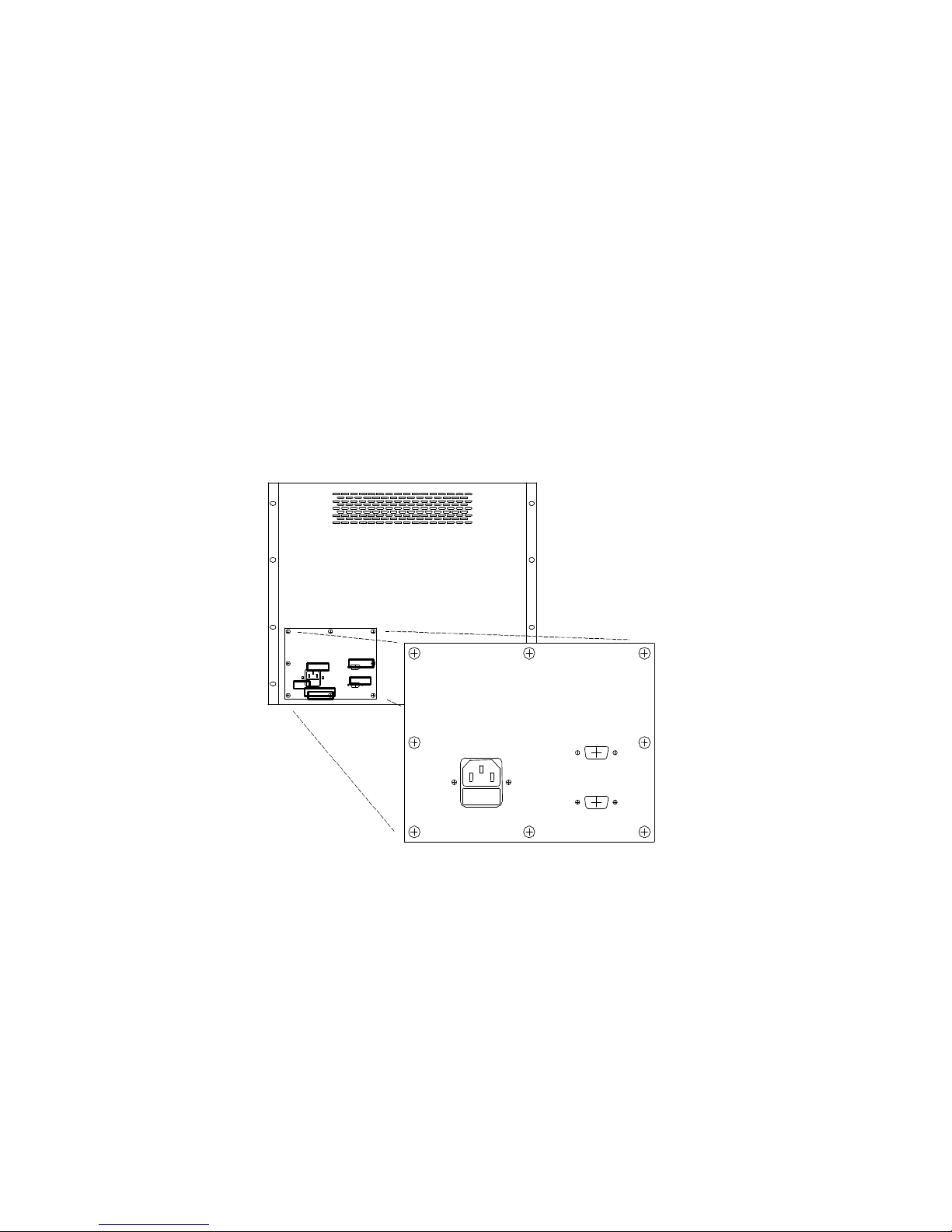
Please refer to the following figure for location of the HD-15 connector on the monitor’s rear
panel.
VIDEO IN
POWER
85-265 VAC
SERIAL
47-440Hz
VIDEO IN
SERIAL
FUSE
POWER
47-440HZ
FUSE
Figure 1 -- Rear view of 3018/19 showing connectors
MAKING POWER AND GROUND CONNECTIONS
AC Power
A monitor equipped for operation on AC power should be connected to a single-phase power
source providing 115 to 230VAC nominal (85 to 264VAC) at 47 to 66Hz, or 400Hz.
Copyright © 2002 -6- by EDL Displays, Inc.
User’s Manual
Connection is made by way of an IEC power cord at the monitor’s power input connector, or
by way of a military style connector, when that option is specified. (See figure above for the
location of the input connector on the monitor’s rear panel.)
WARNING: To ensure against fire or shock hazards, the monitor chassis
should be connected to an earth ground by a path that is independent of the
power cord. While the AC power cord provides a ground wire, the power
cord ground can be defeated by use of an extension cord or 3-prong to 2prong AC adapter, and it can be rendered ineffective by improper wiring of
the AC receptacle.
NOTE: To minimize ground loop induced “noise” on the video inputs, it is
good practice to connect the monitor’s AC power cord to the same receptacle
that supplies power to the video source.
DC Power
A monitor equipped for operation from a DC power source should be connected to the DC
main using UL approved #10 stranded wire. The wire should use properly color-coded
insulation.
Copyright 2002 -7- by EDL Displays, Inc.
 Loading...