


VPE-300 Series
Installation
Information
Manual Number: TP0801-00
Issue: A1
Date: June 1995

Before You Install
Introduction ...............................................................................................................1-1
Receiving Inspection ................................................................................................1-1
Unpacking Instructions ...........................................................................................1-2
Equipment Inspection ..............................................................................................1-4
Facility Checklist .......................................................................................................1-4
Contents
General Information
Introduction ...............................................................................................................2-1
About The Manual ....................................................................................................2-1
Manual Conventions .........................................................................................2-2
Editor Description ....................................................................................................2-2
Computing Chassis ............................................................................................2-2
Single Board Controller (SBC) ...................................................................2-3
Hard Drive .............................................................................................2-3
Floppy Disk Drives ...............................................................................2-3
Fan .................................................................................................................2-4
DC Power Supply ........................................................................................2-4
Backplane ......................................................................................................2-4
Expansion Chassis ..............................................................................................2-5
Keyboard .............................................................................................................2-5
K2 Keyboard .................................................................................................2-6
K3 Keyboard .................................................................................................2-6
K5 Keyboard (VPE-351 Only) ....................................................................2-7
Specifications .............................................................................................................2-8
Safety ..........................................................................................................................2-9
Environmental Requirements .................................................................................2-9
Installing The Editor
Introduction ...............................................................................................................3-1
The Work Space ........................................................................................................3-1
Cable Information .....................................................................................................3-2
Editor Installation .....................................................................................................3-2
Installing The Computing Chassis ..................................................................3-3
iii

Contents
Expansion Chassis Installation .........................................................................3-7
Placing The Keyboard .......................................................................................3-8
Making The Connections .........................................................................................3-9
Computing Chassis Connections .....................................................................3-9
Expansion Chassis Connections .......................................................................3-13
K5 Keyboard Connections ................................................................................3-14
The Start-up Sequence .............................................................................................3-15
Turning Power On .............................................................................................3-15
Menu Selection And Control ............................................................................3-16
Making Basic Checks ................................................................................................3-19
Machine Assignments .......................................................................................3-19
VTR Machine Assignments ........................................................................3-20
AUX and BLK Crosspoint Assignments ..................................................3-22
Fast Column Data Entry .............................................................................3-23
Other Machine Assignments .....................................................................3-24
Communications Testing ............................................................................3-25
Installation Troubleshooting ...................................................................................3-27
Front Panel Status Indicators ............................................................................3-27
Program Execution ............................................................................................3-28
SBC Switches .......................................................................................................3-28
SBC Jumpers .......................................................................................................3-29
Appendix A – System Differences
Appendix B – Port Availability With Options
Appendix C – K3 Keyboard Information
Introduction ...............................................................................................................C-1
K3 Keyboard New Features ....................................................................................C-1
Embedded Functions ...............................................................................................C-2
Embedded Alpha Character Keystrokes ...............................................................C-3
Keyboard Sensitivity Adjustment ..........................................................................C-4
Uploading/Re-uploading Keyboard Software ....................................................C-5
Troubleshooting After Downloading ....................................................................C-5
Internal Keyboard DIP Switch Settings .................................................................C-6
Appendix D – K2 Keyboard Information
Introduction ...............................................................................................................D-1
Manual Override of Jog Knob Automatic Mode .................................................D-1
Keyboard Sensitivity Adjustment ..........................................................................D-2
Appendix E – Interconnecting Diagrams
Appendix F – System Software Installation
Introduction .........................................................................................................F-1
Installing System Software ...............................................................................F-1
iv

Glossary
List of Figures
No. Title Page
1-1 Unpacking Your Editor.........................................................................1-3
2-1 Editor Computing Chassis....................................................................2-3
2-2 Computing Chassis Rear Panel............................................................2-4
2-3 Expansion Chassis .................................................................................2-5
2-4 K2 QWERTY Style Keyboard...............................................................2-6
2-5 K3 Dedicated Functions Keyboard......................................................2-7
2-6 K5 Keyboard with Jog Panel ................................................................2-7
3-1 Table Top Mounting Foot Installation................................................3-3
3-2 Computing Chassis Handle Installation.............................................3-4
3-3 Handle & Mounting Bracket Attachment ..........................................3-5
3-4 Installing the Computing Chassis Into the Equipment Rack ..........3-6
3-5 Expansion Chassis Installation ............................................................3-7
3-6 Computing Chassis Rear Panel Connectors.......................................3-11
3-7 Expansion Chassis Connectors ............................................................3-13
3-8 K5 Keyboard Connectors......................................................................3-14
3-9 Super Edit Main Menu..........................................................................3-15
3-10 Diagnostics & Test Menu......................................................................3-17
3-11 PROM-based Self-test Results..............................................................3-17
3-12 Boot Device Selection Menu.................................................................3-18
3-13 Machine Assignment Page ...................................................................3-19
3-14 Edit Screen Display................................................................................3-25
3-15 Computing Chassis Front Panel Indicators .......................................3-28
3-16 SBC Switch Locations............................................................................3-28
3-17 Removing the SBC .................................................................................3-29
3-18 SBC Jumper Locations...........................................................................3-30
Contents
E-1 Example of System Interconnection
Without an 8466 Preview Switcher .........................................E-3
E-2 Example of System Interconnection
With an 8466 Preview Switcher ..............................................E-5
v

Contents
List of Tables
No. Title Page
2-1 Physical & Electrical Specifications.....................................................2-8
3-1 Basic Cable Set........................................................................................3-2
3-2 SBC Default Jumper Settings................................................................3-31
3-3 EPROM Selection Jumpers ...................................................................3-32
3-4 Keyboard Baud Rate Selection Jumpers.............................................3-33
A-1 VPE Series Editing Systems Hardware Differences..........................A-1
A-2 VPE Series Editing Systems Software Differences............................A-2
B-1 VPE-SystemVTR Port Availability With GVG Model 100/110, 200
Series, Model 300, 1000, 3000, 4000, GVG Kadenza
or Ampex Vista.......................................................................................B-1
B-2 VPE-SystemVTR Ports Availablility with GVG Ten-XL/Performer,
GVG Model 1600/1680, Ross, CDL, Ampex AVC
or Century ..............................................................................................B-2
vi
Important Safeguards and
Regulatory Notices
Information on the following pages provides important safety guidelines
for both Operator and Service Personnel. Specific warnings and cautions
will be found throughout the manual where they apply, but may not
appear here. Please read and follow the important safety information,
noting especially those instructions related to risk of fire, electric shock or
injury to persons.
WARNING
Any instructions in this manual that require opening the equipment cover or
enclosure are for use by qualified service personnel only. To reduce the risk
of electric shock, do not perform any servicing other than that contained in
the operating instructions unless you are qualified to do so.
Symbols and Their Meanings
The lightning flash with arrowhead symbol, within an equilateral triangle,
alerts the user to the presence of “dangerous voltage” within the
equipment’s enclosure that may be of sufficient magnitude to constitute a
risk of electric shock to persons.
The exclamation point within an equilateral triangle alerts the user to the
presence of important operating and maintenance (servicing) instructions
in the literature accompanying the equipment.
The fuse symbol indicates that the fuse referenced in the text must be
replaced with one having the ratings indicated.
This symbol represents an internal protective grounding terminal. Such a
terminal must be connected to earth ground prior to making any other
connections to the equipment.
v

Safeguards and Notices
Danger
This symbol represents an external protective grounding terminal. Such a
terminal may be connected to earth ground as a supplement to an internal
grounding terminal.
CAUTION
This equipment contains static sensitive components. Use anti-static grounding
equipment whenever handling or servicing modules and components. When circuit
modules are removed from the frame, place them on a flat static-controlled
surface. Failure to follow this precaution can result in component damage due to
electrostatic discharge.
Warnings
Electrical potential is still applied to some internal components even
■
when the power switch/breaker is in the off position. To prevent
electrical shock when working on this equipment, disconnect the AC
line cord from the AC source before working on any internal
components.
■
A residual voltage may be present immediately after unplugging the
system due to slow discharge of large power supply capacitors. Wait 30
seconds to allow capacitors to discharge before working on the system
■
Heed all warnings on the unit and in the operating instructions.
Do not use this equipment in or near water.
■
Disconnect ac power before installing any options.
■
■
The attachment plug receptacles in the vicinity of the equipment are all
to be of a grounding type, and the equipment grounding conductors
serving these are to be connected to earth ground at the service
equipment.
This equipment is grounded through the grounding conductor of the
■
power cord. To avoid electrical shock, connect the power cord to the
equipment and plug it into a properly wired receptacle before
connecting the equipment inputs and outputs.
Route power cords and other cables so that they are not likely to be
■
damaged.
Disconnect power before cleaning. Do not use liquid or aerosol
■
cleaners; use only a damp cloth.
vi

Safeguards and Notices
■
Dangerous voltages exist at several points in this equipment. To avoid
personal injury, refer all servicing to qualified personnel.
■
Do not wear hand jewelry or watches when troubleshooting high
current circuits, such as the power supplies.
■
During installation, do not use the door handles or front panels to lift
the equipment as they may open abruptly and injure you.
To avoid fire hazard, use only components of the the specified type,
■
voltage and current rating as referenced in the appropriate parts list.
Always refer fuse replacement to qualified service personnel.
■
To avoid explosion, do not operate this equipment in an explosive
atmosphere unless it has been specifically certified for such operation.
Have qualified personnel perform safety checks after any completed
■
service.
Risk of electric shock is present. A grounded circuit conductor (neutral)
■
is provided with over current protection. Test all components before
touching.
vii

Safeguards and Notices
Cautions
To prevent damage to equipment when replacing fuses, locate and
■
correct the trouble that caused the fuse to blow before applying power.
■
Verify that all power supply lights are off before removing the power
supply or servicing equipment.
Use only specified replacement parts.
■
■
Follow static precautions at all times when handling this equipment.
■
Leave the back of the frame clear for air exhaust cooling and to allow
room for cabling. Slots and openings in the cabinet are provided for
ventilation. Do not block them.
■
The front door is part of the fire enclosure and should be kept closed
during normal operation.
■
To prevent damage to this equipment read the instructions in this
document for proper input voltage range selection.
Danger of explosion if battery is incorrectly replaced. Replace only with
■
the same or equivalent type recommended by the manufacturer.
Dispose of used batteries according to the manufacturer’s instructions.
■
Circuit boards in this equipment are densely populated with surface
mount and ASIC components. Special tools and techniques are
required to safely and effectively troubleshoot and repair modules that
use SMT or ASIC components. For this reason, service and repair of
products incorporating surface mount technology are supported
only on a module exchange basis. Customers should not attempt to
troubleshoot or repair modules that contain SMT components. Editware
assumes no liability for damage caused by unauthorized repairs. This
applies to both in- and out-of-warranty products.
viii

Power Cord Notices
North American Power Supply Cords
Safeguards and Notices
This equipment is supplied with a molded grounding plug (
at one end and a molded grounding receptacle (IEC 320-C13) at the other
end. Conductors are color coded white (neutral), black (line) and green or
green/yellow (ground).
Operation of this equipment at voltages exceeding 130 Vac will require
power supply cords which comply with NEMA configurations.
International Power Supply Cord
This equipment is supplied with a molded grounding receptacle (IEC 320C13) at one end and stripped conductors (50/5 mm) at the other end.
Conductors are CEE color coded—light blue (neutral), brown (line) and
green/yellow (ground). Other IEC 320 C-13 type power supply cords can
be used if they comply with the safety regulations of the country in which
they are installed.
Black
White
Green or Green
with Yellow stripe
Line
Neutral
Ground
(Earth)
NEMA 5-15P
NOTE: The
illustrated U.S. cord
is for 110/125 Vac
only.
For 220 Vac, the line
cord has two hot
lines and no neutral.
)
Brown
Blue
Green with
Yellow stripe
Line
Neutral
Ground
(Earth)
NOTE: This
international cord is
for both 110 and 220
Vac.
Europe uses singleor 3-phase 230 Vac,
with one hot line and
one neutral.
ix

1
Introduction
Before You Install
Introduction
Congratulations on your purchase of one of the finest video tape editing
systems on the market. The Video Production Editor (VPE) is
manufactured by Editware, Inc., the recognized leader in quality
and service for video tape editing systems. This is the Installation
Instructions manual for the VPE. It covers installation of the VPE models
listed below:
VPE-331
■
■
VPE-341
■
VPE-351
Throughout this manual, when information or discussions are inclusive of
all the models listed above, the VPEs are referred to as the Editor. Where
differences exist, they are so noted. In addition, a table listing the
differences between the Editors is provided in Appendix A.
The next few pages provide information about what to look for when you
receive and unpack your Editor. A facilities checklist is included.
Receiving Inspection
Inspect all shipping containers for any signs of damage. If any is found,
notify the shipping company. If there is no obvious damage, continue with
the unpacking instructions.
1-1
Section 1
— Installing The Editor
Unpacking Instructions
Place the containers on a flat level surface with enough room to move the
containers around as needed. In the Manual Set container, locate the
Manual Set Inventory sheet. Remove all the remaining manuals and the
Floppy Disk software set. Compare the manuals against the Inventory
sheet and make a note of any discrepancies.
GRASS VALLEY GROUP
1-2
Unpacking Instructions
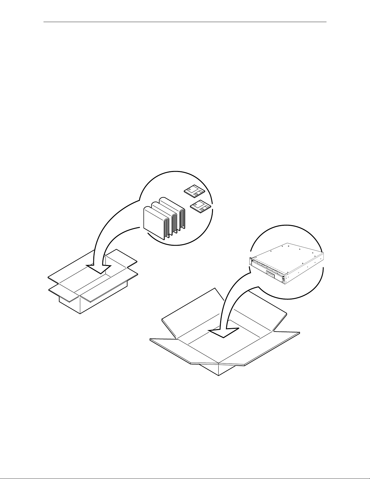
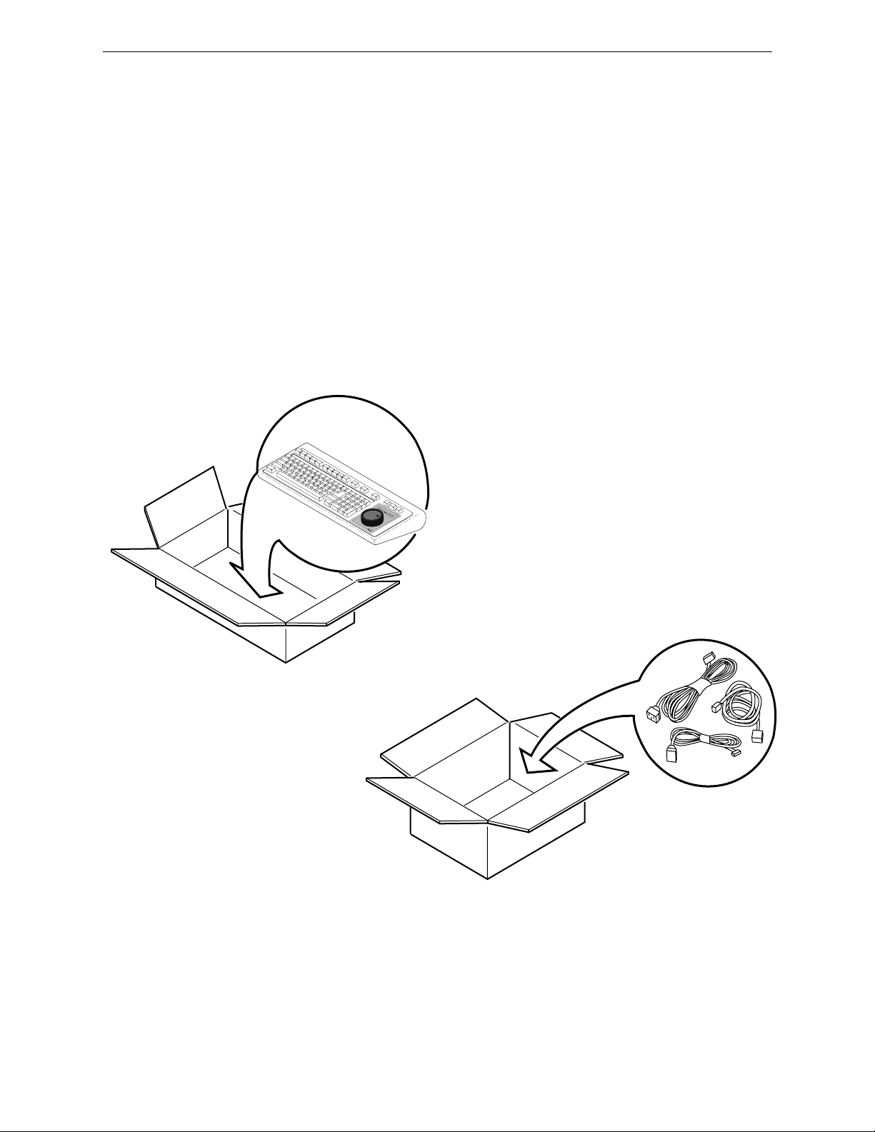
Locate the container with a small plastic pouch taped to its top, open the
pouch, and remove the Packing List. In turn, open each of the remaining
containers. One contains the VPE Chassis. Others contain the Keyboard,
cables, and any other installation hardware. See Figure 1-1. (One or more
options may be in any of these containers.)
Carefully remove the contents of each container and place on a flat level
surface. Compare the contents with the Packing List to ensure that there are
no missing items. Make a note of any discrepancies.
GRASS VALLEY GROUP
0354-00-001
Figure 1-1. Unpacking Your Editor
1-3

Section 1
— Installing The Editor
Equipment Inspection
Inspect all equipment for damage. Items to specifically check, and damage
to look for, are listed below:
All connectors for bent or broken pins
■
Cables for crimped or broken wires
■
■
Floppy diskettes for any obvious signs of damage
If any damage is found, contact Editware Customer Service at the telephone
number in the front of this manual. If any item is damaged, DO NOT make
any power or signal connections to the unit unless otherwise advised to do
so by Editware Customer Service.
If there are any discrepancies between the Manual Set Inventory sheet and
the manuals received, or between the Packing List and items received,
contact Editware Customer Service at the telephone number at the front of this
manual. If there are no discrepancies and either no damage, or GVGadvised correction action is made, continue with this manual.
Facility Checklist
The following checklist is a synopsis of information found in the
appropriate Installation Planning Guide. The Planning Guide should be
referred to for detailed site preparation information.
■
If your facility includes an equipment rack, ensure that the rack is
within 50 feet (16 meters) of your work space.
Ensure that there are sufficient AC power outlets of the required 3-
■
prong grounded type and amp rating for the intended equipment.
■
To maintain consistent signal quality throughout your facility, there
should be a minimum of two Distribution Amplifiers (DAs).
■
Depending on the video switcher, you may need Sync, Subcarrier,
and Blanking in addition to Black Burst.
■
Ensure that the work space is at least large enough to accommodate
the following:
The K2, K3, or K5 Keyboard
One or more monitors
Control Panels for any other equipment
1-4

2
Introduction
General Information
Introduction
If you have not had experience with video tape editing, Editing Systems, or
with Editware, Inc., please take a few minutes to get acquainted
with this manual. Also, we recommend that you read all step-by-step
instructions through at least once before performing them.
About The Manual
Your VPE-300 Series Editor is self-contained and this is the Installation
Instructions manual for it. The manual is part of a Manual Set shipped with
your Editor. A list of available manuals can be found at the front of this
book. For ease of use, the manual is divided into topical sections. Sections
are identified and briefly described below.
General Information
about your Editor. It includes a description of the Editor and its
specifications, power requirements, and environmental & safety
information.
Installing The Editor
on installing your Editor. It has cabling information and a start-up
procedure.
- This section provides introductory material
- This section gives you step-by-step instructions
Glossary
manual which you may not be familiar with. This includes acronyms.
The manual may also contain one or more appendices, which are
supplemental information included as a convenience for you.
- The Glossary is an alphabetical listing of terms used in the
2-1

Section 2
— General Information
Manual Conventions
Items of discussions within a topic are indicated by titles in the right-hand
column. Pages, figures (illustrations), and tables are numbered to reflect
the section of the manual within which they are located. For example, in
this section, page, figure, and table numbers begin with 2-.
NOTE:
section) and return to this section at the completion of installation. However, it is
recommended that you become more familiar with your Editor by continuing with
this section.
Editor Description
At this point, you may want to go directly to Installing The Editor (the next
Your Editor is designed to control videotape machines, video switchers,
and audio mixers in a post-production environment. It can also control
other devices such as a printer. The Editor consists of a Computing Chassis
and a Keyboard, and, for the VPE-351, an Expansion Chassis. A color
monitor is required (purchased separately from Editware and an optional
printer may also be used.
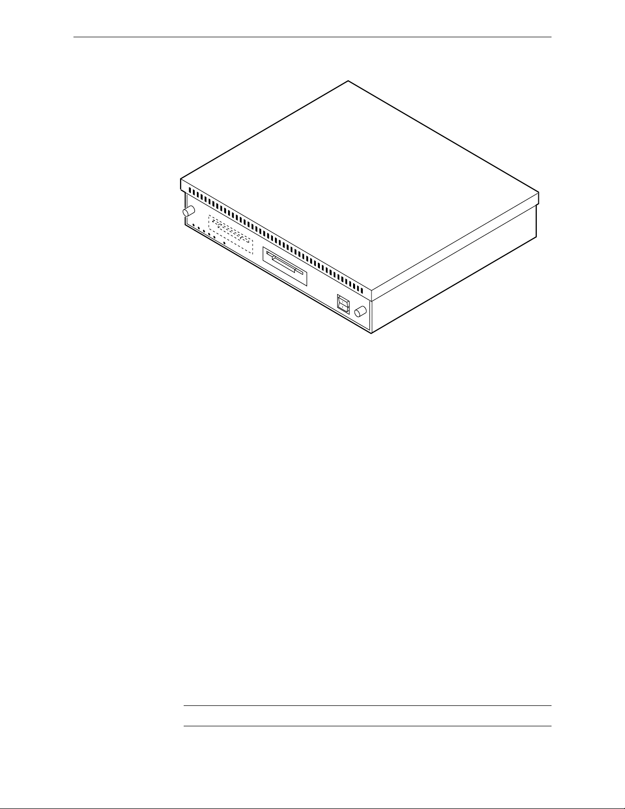
Computing Chassis
The Computing Chassis, illustrated in Figure 2-1, houses the following
components of the Editor:
Single Board Controller
■
Fan
■
■
DC Power Supply
Backplane
■
2-2
Editor Description
0354-00-002
DRIVE 1
DRIVE 0
Figure 2-1. Editor Computing Chassis
Single Board Controller (SBC)
The Single Board Controller, mounted inside the Computing Chassis,
contains the controller and data processing circuitry for the Editor. It
contains all the controls and indicators (except power ON/OFF) for the
Editor.
Hard Drive
All VPE models use a Hard Disk Drive, mounted on the SBC board, for
long term EDL storage.
Floppy Disk Drives
Two 3.5-inch floppy disk drives, mounted on the SBC board and
designated DRIVE Ø (DFØ) and DRIVE 1 (DF1), are standard
equipment. The Drive fronts extend through the front panel for easy
insertion and removal of floppy disks, and viewing the Run indicator
LED on the drives’ fronts. They are designed for use with 720K double-
sided micro-floppy disks (or diskettes).
NOTE:
Do not use high density (1.4Mb) diskettes.
2-3
Section 2
— General Information
Fan
Cooling the Computing Chassis interior is accomplished by a fan mounted
on the rear panel. Fan power is +12 VDC from the DC Power Supply
through the Backplane. Ambient air is drawn in through a filter in the front
and warm interior air is exhausted out the rear of the chassis.
DC Power Supply
The DC Power Supply is mounted on the right-hand side of the Computing
Chassis. It receives 115/230 VAC power from the AC line connector on the
Input Power Filter Housing at the rear of the chassis. The Power Supply
provides the +5 and ±12 VDC voltages required by the Editor. These
outputs are distributed to other components through the Backplane.
Backplane
This is a printed circuit board mounted vertically at the interior rear of the
chassis. The interior side of the Backplane has connectors which interface
power and signals for the Computing Chassis components. For all the
Editors, inputs/outputs for external devices are interfaced to the
Backplane by connectors attached to its exterior side. These connectors
extend through slots on the rear panel. For the VPE-351, the Expansion
Chassis provides additional interfaces for external devices.
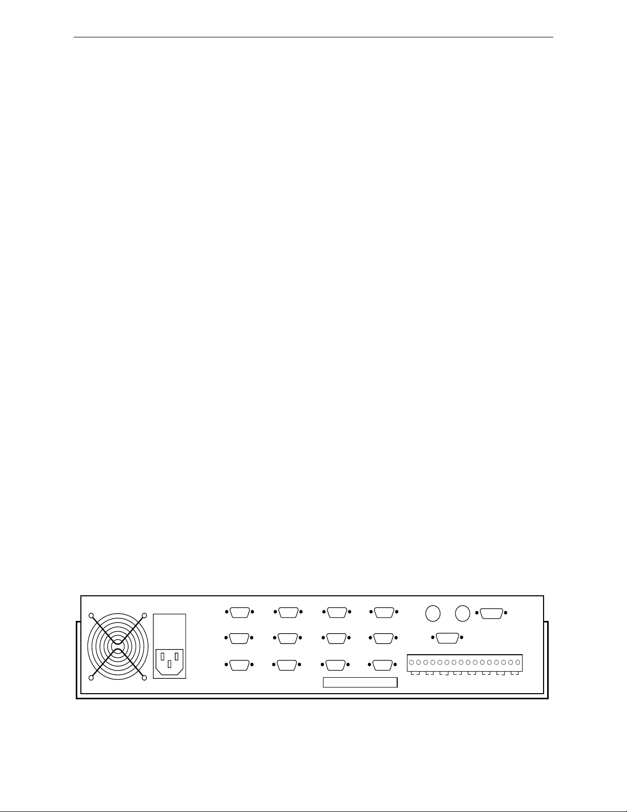
Figure 2-2 shows the rear panel of the Computing Chassis. Backplane
connectors provide signal interfaces between the Computing Chassis, the
Keyboard, the Monitor, peripheral devices, and, for the VPE-351, the
Expansion Chassis. Backplane Connectors are:
■
Fourteen (14) 9-pin D connectors
Two (2) BNC connectors
■
■ A Serial I/O connector.
■ A GPI terminal strip
KEYBOARD
PORT 0
VIDEO CTL PORT 6
AUDIO CTL
PORT 5
PORT 3
PORT 2
PRINTER/COMM
COLOR MONITOR
CFID INSYNC IN
4-00-003
2-4
PORT 7CHAR GEN
PORT 4
PORT 1
Figure 2-2. Computing Chassis Rear Panel
EDIT GPI
8 7654321
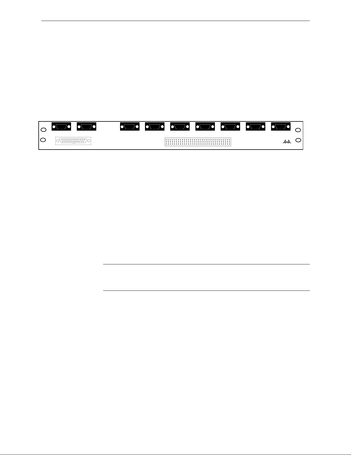
Expansion Chassis
The Expansion Chassis (VPE-351 only), shown in Figure 2-3, consists of
eight (8) 9-pin D connectors and a 64-pin Serial I/O connector. These
connectors provide the signal interfaces between the Expansion Chassis,
the Computing Chassis, peripheral devices, and, if desired, the K5
Keyboard.
Editor Description
1234
5
9876
JOG IN
KBD IN
1234
5
9876
KBD OUT
VPE PORT EXPANDER
Keyboard
The standard Keyboard for your Editor is a model K2 QWERTY style
keyboard. (QWERTY refers to the style of keyboard, similar to a
typewriter, where the top row of letters, from the left, begins with the
letters QWERTY.) An optional K3 style keyboard is available for all models
and an optional K5 Keyboard is available for the VPE-351.
NOTE:
instructions for the AUTO CAL and MANUAL OVERRIDE features of the
Keyboard. See Section 2 of the User’s Guide for additional information.
5
9876
1234
5
9876
1234
5
9876
1234
5
9876
1234
PORT 18 PORT 17 PORT 16 PORT 15
5
9876
1234
5
9876
1234
5
9876
1234
PORT 14 PORT 13 PORT 12
0353-00-060
Editware VPE Series
Figure 2-3. Expansion Chassis
The K2 Keyboard has a sticker on the bottom which provides brief operation
2-5
Section 2
— General Information
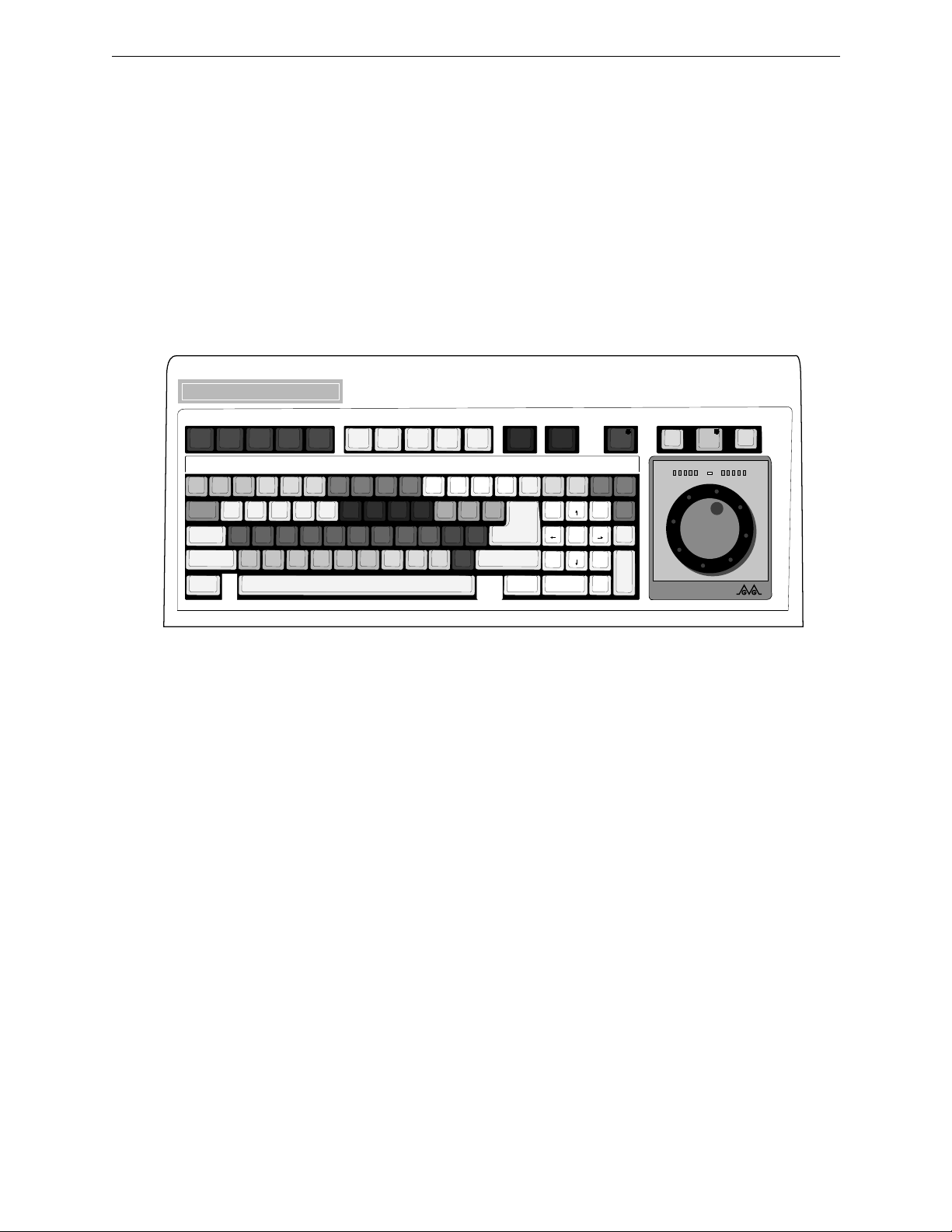
K2 Keyboard
The K2 Keyboard, illustrated in Figure 2-4, includes a Jog Knob. The
Keyboard connects to the KEYBOARD connector at the chassis rear panel.
QWERTY keys are used for normal text entries and for some editing and
control functions. Other keys provide special functions.
The Jog Knob provides efficient machine control. It is a motion sensitive
device allowing quick access to different motion control modes without the
need for additional keystrokes.
VPE-131 Video Production Editor
LEARNMODIRM1INPUTM2OUTPTM3AUTO
OPEN
ASGNSLVSPEGS
END
AUTO
RECORD
CTRL
ALT
RPLAY
ASMB
R-VTR A-VTR B-VTR C-VTR D-VTR E-VTR F-VTR AUX BLK
REW FF PLAY STOP SLOW SRCH
SHIFT
M4
PKUP
CLEAR
SAVE
MARKS
VVV BVB VBV A/V AUDIO VIDEO SPLIT CUT DISS
RESET
RECAL
Figure 2-4. K2 QWERTY Style Keyboard
K3 Keyboard
The K3 Keyboard, illustrated in Figure 2-5, is a dedicated keyboard
designed for fast, news-style functional applications. It also connects to the
KEYBOARD connector. Key layout is designed for maximum speed. This
Keyboard is an option for your Editor. The Jog Knob function is identical
to the one on the K2 keyboard. (See Appendix C for additional information
about the K3 Keyboard.)
RECD
INIT EJECT YES NO
OFF
INSRT
REPL
MOVE
DEL
RIPPL
MARK
MARK
IN
IN
MARK
OUT
INPUT
EDL
CONST RESET
OUTPT
ALT
TC
MARK
VAR
OUT
TRIM
OUT
SET
DUR
-
MARK
IN
GRASS VALLEY GROUP
MATCH
MATCH
MENU
TITLE
UNDO
EDL
EDL
NOTE
KEY
WIPE
MULTI
FILL
SHIFT
RETURN
SET
SET
IN
7
4
1
0 00
TRIM
OUT
IN
98
PG UP
65
SEEK
32
PG DN
ENTER
BKSP
BEGIN
END
FR
2-6
Editor Description
LEARN
VTR
BLK
B
E
SPLITCUT DISS WIPE KEY
MARKINMARK
CUE
OUT
DIR
OUTPT
AUTO
LOAD
M0
M1
M3
M4
M2
PEGS
INPUT
EDL
PKUP
RECAL
AUTO
ASMB
ALT
SHIFT
GANG
SLVS
OUTPT
EDL
INSRT
REPL
SAVE
MARKS
CTRL
ASGN INIT
UNDO
EDL
DEL
CLEAR
RESET
REC
OFF
TITLE
NOTE
MOVE
RPPL
OPEN
MULTI
RESET
ALT
TC
END
FILL
A
REC
VTR
VTR
C
VTRDVTR
VTR
F
AUX
VTR
REW FF PLAY
SLOW VAR
STOP
MATCH
REPLAY
RECORD
PREVIEW
VVV
ALL STOP
MENU
PMTCH
A4VA1A2 A3
BVB VBV YES NO
SRCH CONST CLR BKSP
SET
TRIM
SET
OUT
IN
IN
7
89
BEGIN
PG UP
45
6
SEEK
23
1
PG DN
END
FR
:
000
ENTER
TRIM
OUT
SET
DUR
-
GRASS VALLEY GROUP
Figure 2-5. K3 Dedicated Functions Keyboard
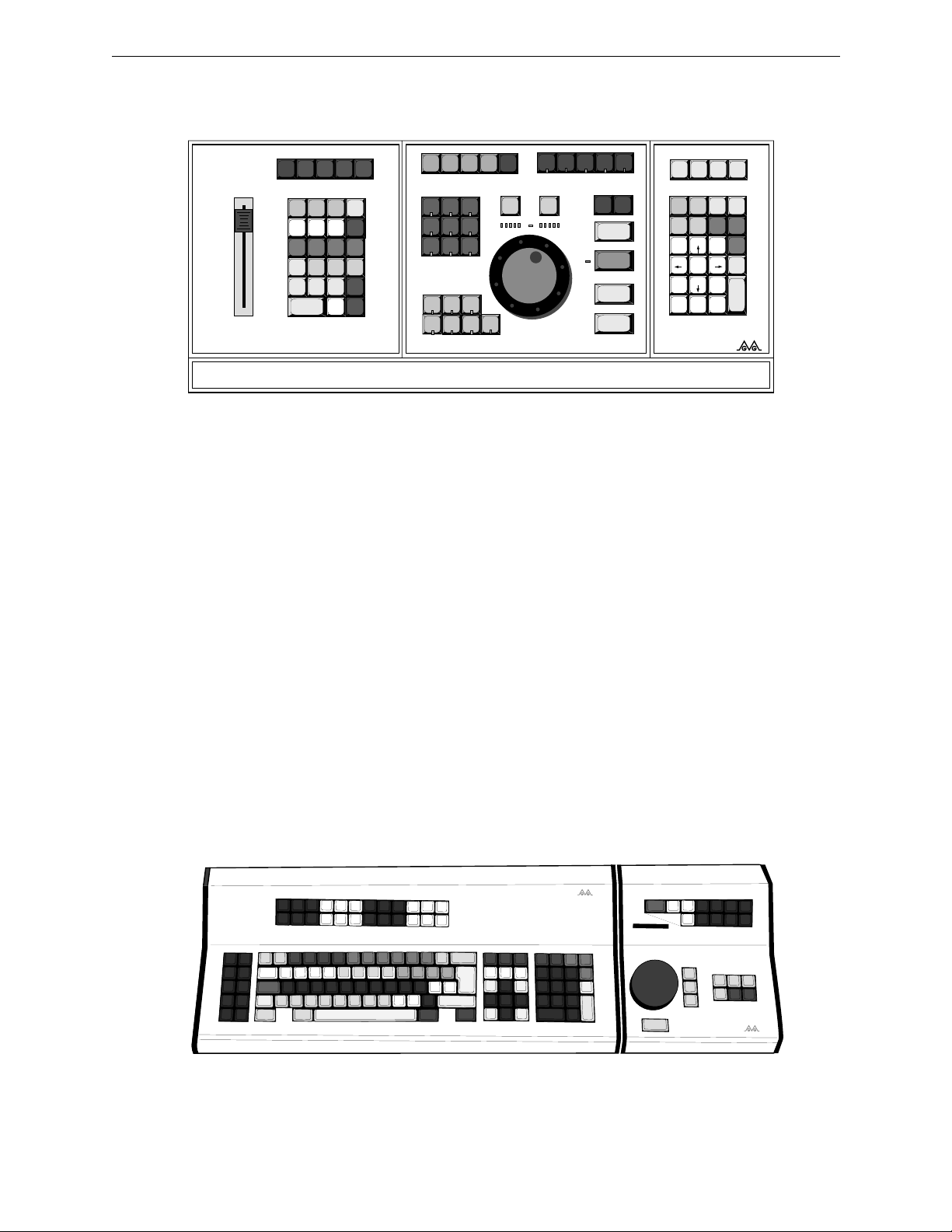
K5 Keyboard (VPE-351 Only)
The K5 Keyboard, illustrated in Figure 2-6, consists of an expanded
keyboard and a separate Jogger panel. The expanded keyboard has special
function keys which replace multiple keystrokes which would otherwise
be needed with other keyboards. This Keyboard has three connectors on its
rear panel. One is for the cable which connects to the Expansion Chassis
and one is for the cable from the Jogger panel. The third connector is for
power to the Keyboard and, through the Keyboard, to the Jogger panel.
The Jogger panel has a Jog Knob and keys which are duplicates of those on
the Keyboard. It also has a direction (forward/reverse) and speed
indicator. The Jogger panel is normally connected to the Keyboard and,
when so connected, receives power from it. However, the Jogger panel
may be connected to the Jogger connector on the Expansion Chassis and
then receives power from the Editor.
0353-355
GRASS VALLEY GROUP
VPE
Figure 2-6. K5 Keyboard with Jog Panel
2-7
Section 2
— General Information
Specifications
The physical and electrical specifications for the Editors are listed in Table
2-1 below.
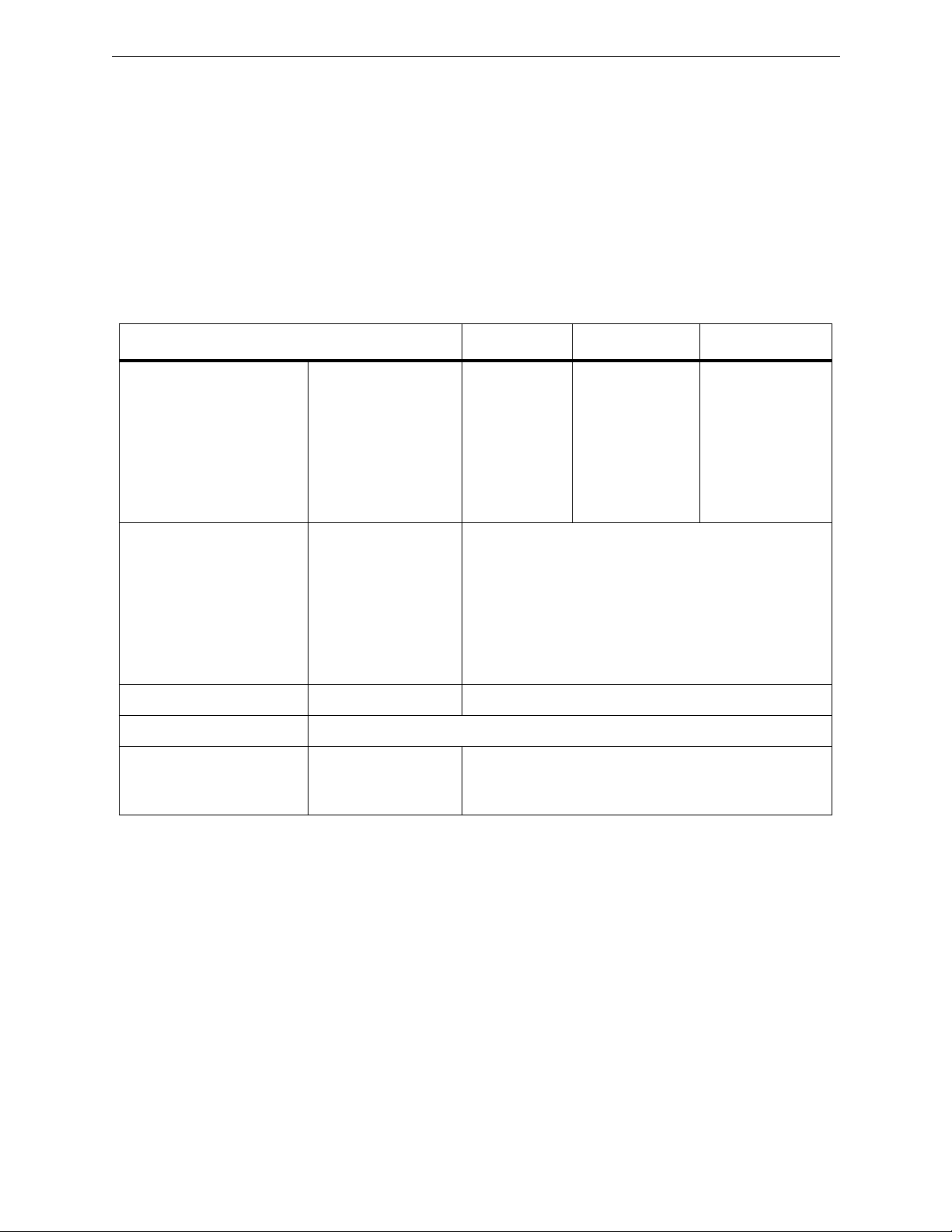
Table 2-1. PHYSICAL & ELECTRICAL SPECIFICATIONS
Height Width Depth
Dimensions Computing Chassis
Expansion Chassis
K2 Keyboard
K3 Keyboard
K5 Keyboard
Jogger Panel
Weight Computing Chassis
Expansion Chassis
K2 Keyboard
K3 Keyboard
K5 Keyboard
Jogger Panel
Power Consumption VPE-300 Series 50W
Input Voltage/Frequency 90 to 264VAC, 47 to 64Hz
DC Power Supply Output 1
Output 2
Output 3
3.5”(8.9cm)
1.6”(4.1cm)
2.0”(5.1cm)
2.0”(5.1cm)
4.0”(10.2cm)
4.0”(10.2cm)
25.0lbs(11.4kg)
1.2lbs(0.5kg)
5.4lbs(2.5kg)
4.8lbs(2.2kg)
7.0lbs(3.2kg)
4.0lbs(1.8kg)
+5VDC, ±0.05VDC, 5.5A
+12VDC, ±0.6VDC, 2.5A
-12VDC, ±0.06VDC, 0.5A
17.0”(43.2cm)*
17.0”(43.2cm)
21”(53.3cm)
21”(53.3cm)
21.8”(55.2cm)
8”(20.3cm)
19.0”(40.0cm)**
1.0”(2.5cm)
9.0”(22.9cm)
9.0”(22.9cm)
9.5”(24.1cm)
9.5”(24.1cm)
* Add 2.0”(5.1cm) for brackets on rack mounted unit.
** Add 1.5”(3.8cm) for brackets on rack mounted unit.
NOTE: Dimensions do not include clearances for cabling and air flow.
2-8

Safety
Your Editor has been designed to meet UL1419 (3rd Revision) Safety
standards. It has also been designed to conform to the emission standards
of FCC Part 15, sub-part J for Class A computing equipment.
Environmental Requirements
Your Editor has been designed to operate efficiently in an environment
with temperatures of from 0 to 50 degrees Celsius in up to 90% noncondensing humidity.
Safety
2-9

3
Introduction
The W ork Space
Installing The Editor
In this section you are given step-by-step instructions on how to install
your Editor. We recommend that you read all instructions thoroughly at
least once before doing them. The section includes:
■ Things to consider when selecting a work space
■ Information on cables
■ The physical installation of the Editor
■ A start-up/power on procedure
The following is a synopsis of work space considerations when installing
your Editor. For more complete information, consult the appropriate
Installation Planning Guide. The Computing Chassis for your Editor is
designed such that it may either be mounted in a standard 19" electronic
equipment rack or placed on a level desk or table top. This, along with
room for the Keyboard, are considerations in determining the work space.
Other considerations are:
■ The proximity of electrical outlets. (The power cord for the
Computing Chassis is 6' long.)
■ Signal cables are 16 meters (approximately 52') long.
■ Routing of power cords and signal cables so that they do not
present a hazard to personnel.
3-1
Section 3
— Installing The Editor
Cable Information
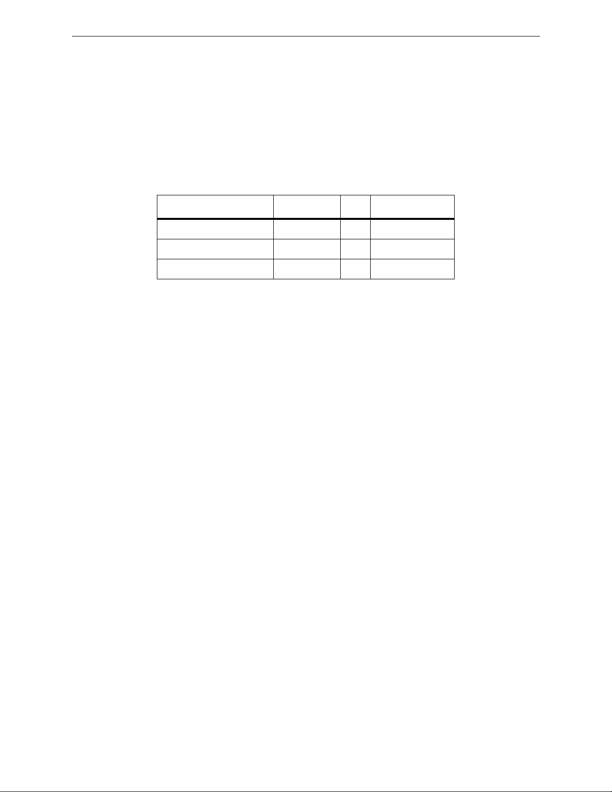
Your Editor system was shipped with a set of cables. The number of cables
depends on which Editor you ordered and what, if any, options were
ordered in addition to the basic system. Cables supplied with a basic
system are listed in Table 3-1.
Echo Plug 054557-00 1 for maintenance
Printer Cable 054591-16 1 to a printer
Machine Control Cable 054602-16 * to VTRs/ATR
* 4 for the VPE-331
7 for the VPE-341
14 for the VPE-351
Table 3-1. BASIC CABLE SET
Name Part Number Qty Destination/Use
Editor Installation
Installing your Editor consists of installing the Computing Chassis and, for
a VPE-351, the Expansion Chassis; placing the Keyboard in the work space;
and then making the power cord and signal cable connections. These are
discussed in turn on the following pages.
3-2
Installing The Computing Chassis
In installing the Computing Chassis, the first thing to determine is whether
it is to be mounted in an equipment rack or placed on a console or table top.
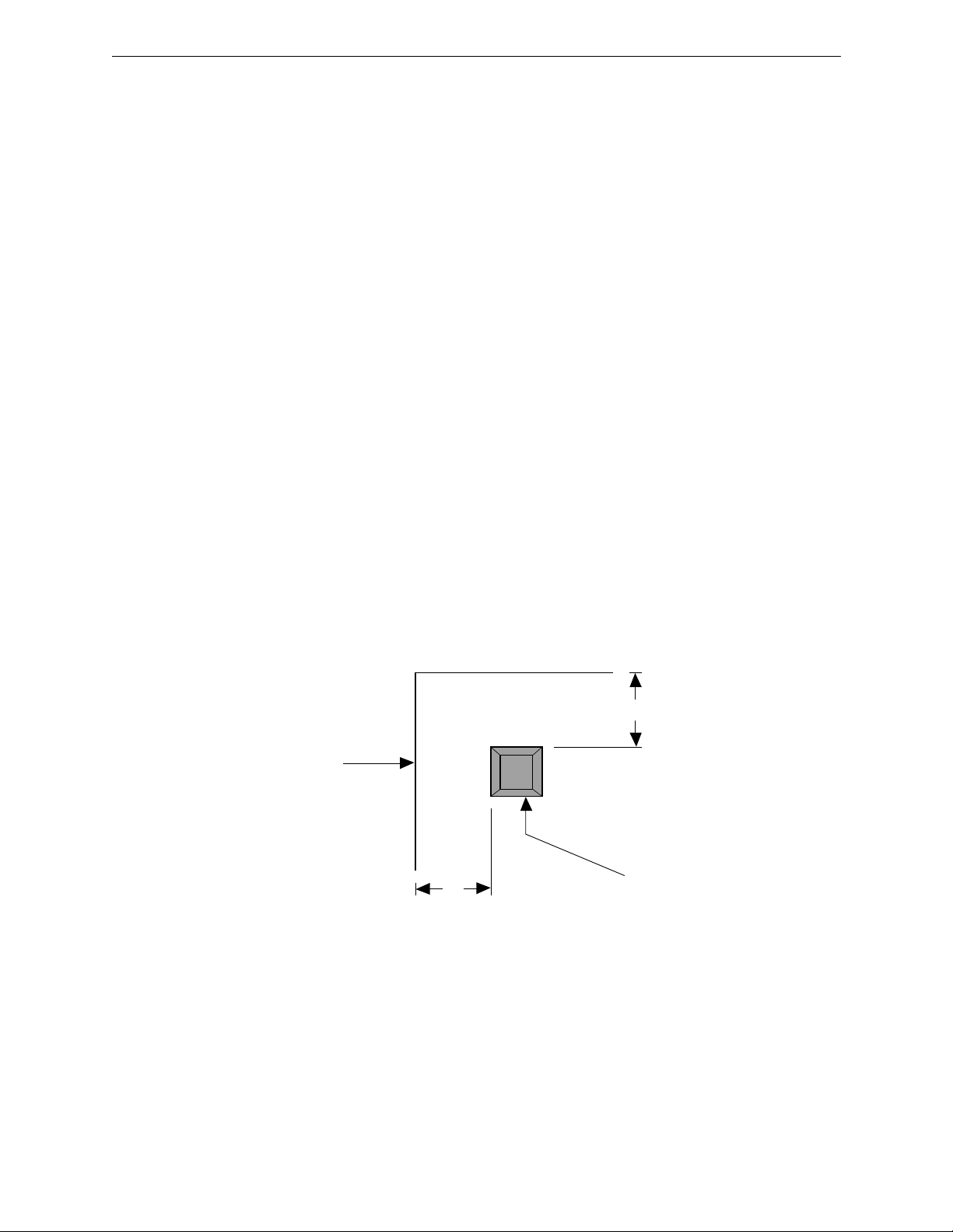
Console or Table Top Installation
If the Chassis is to be placed on a console or table top, you may want to
protect that surface by installing the four rubber feet provided as
illustrated in Figure 3-1. To install the rubber feet, refer to Figure 3-1 and
perform the following procedure:
1. Locate the bag containing four grey mounting feet and remove
them from the bag.
2. Carefully turn the Computing Chassis over and place it on a flat
level work area on its top side.
3. One at a time, remove the backing from each foot and firmly press
into place approximately 1" in from each side at the corners on the
bottom plate. (See Figure 3-1.)
Editor Installation
4. Carefully turn the Computing Chassis back over until it is resting
Computing Chassis Side
on the mounting feet.
0354-00-006
1"
Desk-top Mounting Foot
1"
Figure 3-1. Table Top Mounting Foot Installation
3-3

Section 3
— Installing The Editor
Equipment Rack Installation
If the Computing Chassis is to be mounted in an equipment rack, mounting
hardware must first be attached to the unit. Hardware consists of handles,
mounting brackets and support brackets. Figure 3-2 illustrates handle
assembly which must be done before attachment to the Chassis. Figure 3-3
illustrates attachment of the handles and mounting brackets to the Chassis.
Figure 3-4 shows installation of the Chassis into the rack.
To attach the hardware and install the Computing Chassis into the
equipment rack, refer to Figure 3-2, 3-3, and 3-4 and proceed as follows:
1. Position the Handle, Face Plate, and Mounting Bracket together as
shown in Figure 3-2.
Mounting Bracket
Handle
Face Plate
6-32 X .50
screws
0354-00-007
Figure 3-2. Computing Chassis Handle Installation
3-4
2. Attach the parts using two of the provided 6-32 x.50 screws.
3. Repeat Steps 1 and 2 to assemble the second Handle.
4. Position one Handle against the chassis and attach it with two of the
provided 6-32 x .25 screws as shown in Figure 3-3.
5. Repeat Step 4 to attach the second Handle.

Editor Installation
6. Position one of the mounting brackets at the side of the unit as
shown in Figure 3-3 and attach it with six of the provided 8-32 x.25
screws.
7. Repeat Step 6 to attach the other mounting bracket.
Mounting Brackets
(one each side)
PGM
NO
SYNC
DC
LOW
FAIL
RUN
POWER
DRIVE 0
GRASS VALLEY GROUP
Handle Assembly
(one each side)
8-32 x 0.25
(six each side)
0354-00-308
6-32 x 0.25
(two each side)
Figure 3-3. Handle & Mounting Bracket Attachment
NOTE: Due to differences in racks, screws for attaching equipment to the rack are
not provided.
3-5

Section 3
— Installing The Editor
8. Attach one of the support brackets to the back of the equipment
rack at the height for the Chassis when installed in the rack. (See
Figure 3-4.)
PGM
NO
SYNC
DC
LOW
FAIL
RUN
POWER
DRIVE 0
Support Brackets
(one each side)
GRASS VALLEY GROUP
Figure 3-4. Installing The Computing Chassis Into The Equipment Rack
9. Repeat Step 8 to attach the other support bracket, being sure it is at
the same height.
10. Supporting the unit, slide the rear of the mounting brackets on the
Computing Chassis into the support brackets attached in Steps 8
and 9 and secure it to the equipment rack with two screws on each
side at the handles.
This completes installation of the Computing Chassis into the equipment
rack. If you are installing a VPE-351, proceed to Installing The Expansion
Chassis. Otherwise, proceed with placing the Keyboard in the work space
and then making power cord and signal cable connections.
0354-00-309
3-6

Expansion Chassis Installation
Although the Expansion Chassis may be placed on a desk, it is
recommended that it be installed in the equipment rack, preferably at the
rear of the rack. This will ensure that cables connected to the Chassis do not
impede access to the front of the rack. The Expansion Chassis must be
within 3 ft. (1 meter) of the Computing Chassis.
Figure 3-5 illustrates installation of the Expansion Chassis. To install the
Expansion Chassis, refer to Figure 3-5. With the Chassis at a convenient
height, use two rack mounting screws on each side to secure the Chassis to
the equipment rack.
Editor Installation
0354-01-009
5
4
3
2
9
1
8
7
6
JOG IN
5
4
3
2
9
1
8
7
6
KBD OUT PORT 18 PORT 17 PORT 16 PORT 15
KBD IN
VPE PORT EXPANDER
5
4
3
2
9
1
8
7
6
5
4
3
2
9
8
7
Figure 3-5. Expansion Chassis Installation
1
6
5
4
3
2
9
1
8
7
6
5
4
3
2
9
1
8
7
6
5
4
3
2
9
1
8
7
6
PORT 14 PORT 13 PORT 12
5
4
3
2
9
1
8
7
6
Grass Valley Group
5
4
3
2
9
1
8
7
6
3-7

Section 3
— Installing The Editor
Placing The Keyboard
The Keyboard is essentially the control panel in the editing environment.
As such, you want to place it in a central location where other equipment
is both visually and physically at hand. Ensure that it is within 16 meters
(approximately 52 feet) of the Computing Chassis and, if using the optional
K5 Keyboard, within 2 meters (6 feet) of a power source.
NOTE: If you are using the K2 Keyboard extension cable, you must attach the
cable grounding wire to an earth ground.
3-8

Making The Connections
For the VPE-300 Series, connections are made at connectors on the rear
panel of the Computing Chassis. For the VPE-351, additional connections
are made to the Expansion Chassis. Also, for a VPE-351 using the K5
Keyboard, connection for that Keyboard is made on the Expansion Chassis.
Appendix E contains some typical interconnecting diagrams.
Computing Chassis Connections
Figure 3-6 illustrates the rear panel of the Computing Chassis and
identifies the connections which will be made to it. To make these
connections, refer to Figure 3-6 and proceed as follows:
Making The Connections
CAUTION
Ensure that the routing of signal cables and power cords does not present a hazard
to personnel or equipment.
1. Ensure that power switches of all equipment to be connected are
OFF.
2. Connect AC power cords of all equipment to AC power outlets.
NOTE: The remainder of this procedure is the suggested order of making
connections. However, there is no recommended priority for connections.
3. If you have a Character Generator, attach the signal cable from it to
the CHR GEN connector.
4. Attach the provided VTR cables from the VTRs to the appropriate
PORT 1 - PORT 7 connectors. (See the NOTES on Figure 3-6 and
especially Appendix B for additional information on VTR port
availability and connections.)
Note that connection to these ports does not assign VTRs to the ports. That
is done through software during the Start-up Sequence.
3-9

Section 3
— Installing The Editor
For Connection of a K2 or
K3 Keyboard (not used
with a K5 Keyboard)
5. If using a peripheral device, such as a Zaxcom, attach the cable from
it to the PORT Ø connector.
6. Attach a K2 or K3 Keyboard cable to the KEYBOARD connector.
(The K5 Keyboard installation will be made later.) Note that if you
are using the K2 Keyboard extension cable, you must attach the
cable grounding wire to an earth ground.
For Connection of
For Connection
of the Audio
Mixer
the Video Switcher
or the 8466 Preview
Switcher
The AC Power
Cord Connector
For Connection of
a peripheral (such
as a Zaxcom)
KEYBOARD
PORT Ø
For Connection
of the Character
Generator
For Connection of
either a VTR, the 8465
Preview Switcher, or a
VIDEO CTL
AUDIO CTL
PORT 7CHAR GEN
Preview Preselector
NOTES
With the VPE-331, neither a Preview Preselector nor the 8465 Preview Switcher can be used. Although
you may connect VTRs to as many ports as are available, you may only assign up to 4 ports.
With the VPE-341 and -351:
If using an 8465 Preview Switcher and a Preview Preselector, the 8465 is connected to
PORT 7 and the Preview Preselector is connected to PORT 6.
If using a Preview Preselector and NOT an 8465, the Preview Preselector is connected to PORT 7.
3-10

Making The Connections
7. Attach the signal cable from the Audio Mixer to the AUDIO CTL
connector.
8. If using an 8466 Preview Switcher with a GVG serial video
switcher, attach the signal cable from the 8466 to the VIDEO CTL
connector. If not, attach the Video Switcher to the VIDEO CTL
connector. (Also see Appendix B.)
PORT 6
PORT 5
PORT 4
For connection of
either a VTR or a
Preview Preselector
PORT 3
PORT 2
PORT 1
For Connection
of the Sync
Source
PRINTER/COMM
8 7654321
For Connection of
the Color Frame
ID (CFID)
COLOR MONITOR
CFID INSYNC IN
EDIT GPI
For Connection
of the Color
VGA Monitor
0354-00-010
PORT 1 - PORT 5 for
Connection VTRs
For connection
of the VPE-351
Expansion Chassis
Figure 3-6. Computing Chassis Rear Panel Connectors
For Connection of
an Optional Printer
For Connection of
Devices for General
Purpose Interface (GPI)
Triggered Events
3-11

Section 3
— Installing The Editor
9. See the NOTES on Figure 3-6 if using an 8465 or 8466 Preview
Switcher and/or a Preview Preselector. Also see Appendix B.
10. Make appropriate connections to the EDIT GPI connector.
11. If using a Printer, attach the provided cable from the printer to the
PRINTER/COMM connector.
12. Attach a cable with BNC connectors from a composite video Sync
generator to the SYNC IN connector.
13. If a CFID signal is available, attach a cable with BNC connectors
from the CFID source to the CFID IN connector.
14. Attach the cable from your VGA Monitor to the COLOR MONITOR
connector.
This completes the physical installation of the Computing Chassis for the
VPE-300 Series. If you are installing a VPE-351, continue on with making
the Expansion Chassis connections. Otherwise, proceed to the Start-up
Sequence.
3-12

Expansion Chassis Connections
Figure 3-7 illustrates the rear panel of the Expansion Chassis and identifies
the connections which will be made to it. To make these connections, refer
to Figure 3-7 and perform the following procedure:
1.Attach the provided ribbon cable from the Computing Chassis I/O
connector to the Expansion Chassis 96-pin connector.
2.Attach the provided VTR cables from the VTRs to the PORT 12 PORT 18 connectors.
This completes physical installation of the VPE-351 Editor. However, if you
are using a K5 Keyboard, continue with K5 Keyboard Connections listed
on the following page. Otherwise, proceed to the Start-up Sequence.
Making The Connections
Not used at
connector on the Computing Chassis
this time
1234
5
9876
JOG IN
KBD IN
5
9876
KBD OUT
For the optional
K5 Keyboard cable
For the cable to the KEYBOARD
if using the optional K5 Keyboard
1234
5
9876
PORT 18 PORT 17 PORT 16 PORT 15
VPE PORT EXPANDER
1234
5
9876
1234
Figure 3-7. Expansion Chassis Connectors
For VTR machine
control cables
5
9876
1234
5
9876
1234
1234
5
9876
1234
5
9876
PORT 14 PORT 13 PORT 12
1234
5
9876
Editware VPE Series
0353-00-360
For the cable to the
Computing Chassis
3-13

Section 3
— Installing The Editor
K5 Keyboard Connections
Figure 3-8 illustrates the rear panel of the K5 Keyboard and identifies the
connections which will be made to it. To make these connections, refer to
Figure 3-8 and proceed as follows:
1. Attach the keyboard cable from the RACK connector on the
Keyboard to the KEYBOARD connector on the Expansion Chassis.
2. Attach the power cable from the POWER connector on the Keyboard to an AC Power outlet.
3. Attach the cable from the Jogger panel to the JOG connector on the
Keyboard.
JOG (J5)
POWER (J2)
RACK (J1)
0353-359
Rear View - K5 Keyboard
Figure 3-8. K5 Keyboard Connectors
4. If using the K5 Keyboard
a. Attach the K5 Keyboard cable to the KBD IN connector.
3-14
b. Attach the provided cable from the KBD OUT connector on the
Expansion Chassis to the KEYBOARD connector on the
Computing Chassis.
This completes physical installation of the K5 Keyboard. Proceed to the
Start-up Sequence.

The Start-up Sequence
The following provides information to ensure that your Editing system is
properly installed and ready for use. It begins with turning power on and
Monitor Settings, goes on to Making Assignments and Basic Checks, and
then concludes with installation troubleshooting.
Turning Power On
The recommended order for turning the power on to your editing system
is as follows:
■ All VTRs and ATR(s)
■ The video switcher and the audio mixer
■ The printer, monitor(s), and peripheral equipment
The Start-up Sequence
■ The Editor Computing Chassis
After power up the Super Edit™ Main Menu, illustrated in Figure 3-9,
appears on the screen. (Super Edit is the software program for your Editor.)
If the Main Menu does not appear, see Installation Troubleshooting and/
or Appendix F, System Software Installation.
Grass Valley Group - Video Tape Editing Systems
VPE-351 menu (V7.1)
Super Edit
EDL Utilities
System Utilities
Diagnostics & tests
Index of menu items
Use arrows for up or down, [->] to select, [-<] to deselect.
Super Edit
Run Super Edit
Initialize a disk
Format, Init disk
Install SE from disk
Super Edit
>Return to edit
TP0353-59
Press the [RESET] key for help information here.
Figure 3-9. Super Edit Main Menu
3-15

Section 3
— Installing The Editor
Menu Selection And Control
The MENU is divided into three sections on the editor screen. Use the [→]
and [←] keys to move through the sections and use the [↑] and [↓] keys to
move the cursor (>) up and down within the selected section.
T o execute a MENU item, select it with the cursor and pr ess [ENTER]. This
accesses the feature, or in some instances, presents you with a sub-menu or
prompt. Prompts appear at the bottom of the screen and request user
specific information (e.g, FROM DRIVE), TO DRIVE), etc.).
Pressing [←] with the cursor in the left column, places the system in the
RT-11 operating system environment. To return to the Main Menu with a
K2 Keyboard, type MENU at the RT> prompt and press [ENTER]; with a
K5 Keyboard, press [MAIN MENU]; with a K3 keyboard press [SHIFT]
[MENU].
Running PROM-based Self Test
1. Use the [←], [→], [↑], and [↓] keys until the Diagnostics & Tests
selection in the left hand column is highlighted and press [ENTER].
The Diagnostics & tests menu appears. (See Figure 3-10 for an example.)
2. Use the [←], [→], [↑], and [↓] keys until the PROM-based self-test
selection is highlighted and press [ENTER]. After a few moments,
test results appear. (See Figure 3-11 for an example.)
3-16

Grass Valley Group - Video Tape Editing Systems
The Start-up Sequence
TP0353-23
VPE-351 menu (V7.1)
Super Edit
EDL Utilities
System Utilities
Diagnostics & tests
Index of menu items
Diagnostics & Tests
>Sync Test
Printer test
Keyboard test
Jogger test
Serial port test
String utility
GPI exerciser
System configuration
PROM-based self-test
Use arrows for up or down, [->] to select, [-<] to deselect.
Press the [RESET] key for help information here.
Figure 3-10. Diagnostics & Test Menu
TP0353-24
DIAGNOSTICS SELFTEST V4.0
VPE-351
CONNECTED
OK
OK
OK
OK
OK
OK
OK
OK
OK
OK
OK
OK
OK
VIDEO DISPLAY CONTROLLER---------PROCESSOR------------------------HARDWARE IS AN SBCIV--------SYSTEM PROM----------------------KEYBOARD PORT--------------------RAMDISK ADDDRESS ---030000
DMA CONTROLLER-------------------MAIN MEMORY 512K-----VIDEO DISPLAY 64K-----FLOPPY DISK CONTROLLER-----------SYNC INTERRUPT-------------------COLOR FRAME ID------------ALL I/O PORTS--------------------MODEM RESPONDED------------------CALENDAR CLOCK-------------------GPI CONTROL-----------------------
PRESS: [ANY KEY] WHEN READY TO CONTINUE
Figure 3-11. PROM-based Self-test Results
3-17

Section 3
— Installing The Editor
3. Press any key. The Boot Device Selection menu appears. (See Figure
3-12 for an example.)
DIAGNOSTICS: BOOT DEVICE SELECTION MENU
CONTINUE: MORE DIAGNOSTICS
RERUN POWER-UP DIAGNOSTICS
BOOT FROM RAMDISK VM0:
BOOT FROM FLOPPY DISK DF0:
BOOT FROM FLOPPY DISK DF1:
BOOT FROM HARD DISK DH0:
BOOT FROM HARD DISK DH1:
TP0353-47
[ ARROWS ] = UP AND DOWN [ ENTER ] = MAKE SELECTION [ TRIM ] = VIEW ERROR
Figure 3-12. Boot Device Selection Menu
4. Use the [←], [→], [↑], and [↓] keys until the BOOT FROM
HARD DRIVE DH0: selection is highlighted and then press
[ENTER]. After a few seconds, the Main Menu appears.
This concludes the Turning Power On procedure. Continue on to Making
Basic Checks.
3-18

Making Basic Checks
Making Basic Checks consists of making the assignments listed below and
discussed on the following pages and then doing Communications Testing.
■ Assign VTR control ports
■ Assign video crosspoints
■ Assign audio crosspoints
■ VTR Model/Manufacturer Assignments
■ Set VTR Sync QC
Machine Assignments
Machine assignments allow you to assign control ports, video crosspoints,
and audio crosspoints, and to identify the VTR model/manufacturer to the
software. These assignments are made from the Assignment Page and
must be done prior to editing. An example of an Assignment Page is
illustrated in Figure 3-13.
Making Basic Checks
LABEL REEL PORT MODEL QC VIDX AUDX PSLX CFRM TYPES AVAILABLE
R-VTR 001 01 -- 03 000 000 01 00 00 = BETA-SP
A-VTR 002 02 -- 03 001 001 02 00 01 = VPR3
B-VTR 003 03 -- 03 002 002 03 00 02 = AJD350
C-VTR --- -- -- -- --- ---
D-VTR --- -- -- -- --- ---
E-VTR --- -- -- -- --- ---
F-VTR --- -- -- -- --- ---
AUX AUX 007 007
BLK BLK 000 000
PVWSW 8466 PORT 09 38.4 ODD
VIDSW GVG100 PORT 09 38.4 ODD
MIXER AMX170 PORT 08 38.4 ODD
PRSEL GV10XL PORT -PERIF NONE PORT -CHRGN NONE PORT --
ASGN=GREEN KEYS OR ALLSTP NO=DEASGN SCROLL=ARROWS RESET=EXIT
Figure 3-13. Machine Assignment Page
TP0353-80
3-19

Section 3
— Installing The Editor
The Assignment Page consists of essentially three sections. The first
section, headed by LABEL, REEL, PORT, etc., identifies machines (and
AUX and BLK) to be assigned. Note that the lower portion of this section is
used to identify devices other than VTRs and the headings do not apply.
The second section, TYPES AVAILABLE, lists the models of VTRs (and
codes) to which you have protocols included in your Super Edit™
software. Basic instructions for the Assignment Page are in the third section
at the bottom.
Note the following:
■ A [NO] to a question de-assigns the selected VTR (i.e., makes it
unavailable).
■ For a VTR, AUX, and BLK to appear in the Mark Table, VTRs must
be assigned via the Assignment Page, and AUX and BLK must have
crosspoints.
■ Pressing [ENTER] at a prompt accepts the factory default setting.
■ You may exit the Assignment Page by pressing either [RESET] or
an invalid key at any time as long as you ar
■ Cable connections between the VTRs and the video switcher and
audio mixer must be known before making video and audio
crosspoint assignments.
VTR Machine Assignments
To make Machine Assignments, follow the steps listed below:
1. With a K2 Keyboard, press [SHIFT][ASGN]; with a K5 Keyboard, pr ess
[VTR ASGN]. A display similar to Figure 3-13 appears with the
R-VTR device (top line) highlighted.
2. If you are making assignments for the R-VTR, press [ENTER] or
[SPACEBAR] (K2 /K5), or [ALL STOP] (K3). Otherwise, either press
the appropriate green key or use [↑] and [↓] to highlight the desired
machine and press [ENTER]. At the bottom left hand corner , the system
prompts:
e not at a prompt.
ENTER REEL #
3-20
3. Enter up to six alphanumeric characters, and then press [ENTER]. The
Reel ID you entered appears on the line with the selected device and the
REEL ID in the Mark Table changes accordingly. The system prompts:
PORT = ?

Making Basic Checks
Before making port assignments, note the following items:
■ You cannot assign more software ports than hardware ports
connected.
■ Multiple keys may not be assigned to the same port.
■ VTR (green) keys should be assigned to only those ports having
machines attached and set for remote operation.
■ For the VPE, the following are factory set port assignments:
PORT 8 - Audio mixer
PORT 9 - Video Switcher
PORT 10 - Character Generator
■ For the VPE-351, the factory set assignment for PORT 11 is the
JOGGER panel.
4. Enter the port number to which the selected machine is connected at
the Editor chassis rear panel (e.g., if the R-VTR is connected to PORT 1,
enter 01) and then press [ENTER]. The port number you entered
appears on the line with the selected device and the system prompts:
MODEL = ?
5. Enter the number from the right-hand column of Figure 3-15 which
corresponds to the VTR you are using for the selected VTR and press
[ENTER]. (For example, if the R-VTR is a VPR-3, you would enter 01.)
The model code you entered appears on the line with the selected
device and the system prompts:
QC VALUE = ?
6. The default QC value is 3. To accept this value, press [ENTER] or enter
a value from -1 to 5 and then press [ENTER]. Note that a QC value
of -1 tells Super Edit™ to make every attempt to synchronize the
machine right up to the IN-point, but DO NOT abort the edit if the
source is not properly positioned. The edit will occur and, based on the
machine assignment, Super Edit™ will attempt to have the source
properly positioned for the event. The QC value you entered appears
on the line with the selected device and the system prompts:
VID XPNT = ?
Before making video crosspoint assignments, note the following items:
■ Color bars, digital effects systems, cameras, and other special video
signals can also be assigned to switcher crosspoints.
■ For E-E previewing, the R-VTR cannot be changed from crosspoint
zero.
3-21

Section 3
— Installing The Editor
7. Enter the desired video crosspoint and press [ENTER]. The video
crosspoint you entered appears on the line with the selected device and
the system prompts:
AUD XPNT = ?
Before making audio crosspoint assignments, note the following items:
■ Non-audio sources are assigned to crosspoint 0.
■ For E-E previewing, the R-VTR cannot be changed from crosspoint
zero.
8. Enter the desired audio crosspoint and press [ENTER]. The audio
crosspoint you entered appears on the line with the selected device.
9. If you have the Preview Preselector option, the system prompts:
PRSEL XPNT = ?
10. Enter the desired Preview Preselector crosspoint and press [ENTER].
Your entry appears on the display.
11. Super Edit provides PAL users the opportunity to assign a color frame
offset. Enter the desired color frame offset value (fr om 0 to 3) and press
[ENTER]. The frame offset you entered appears on the display.
12. Repeat Steps 1 through 11 for all connected VTRs.
AUX and BLK Crosspoint Assignments
Default video and audio crosspoints are 007 for AUX and 000 for BLK. To
change the AUX and BLK assignments, perform the following steps:
1. Use [↑] and [↓] to highlight AUX or BLK. The system prompt indicates:
VID XPNT = ?
2. Enter the desired video crosspoint and press [ENTER]. The crosspoint
you entered appears on the selected AUX or BLK line and the system
prompts:
AUD XPNT = ?
3-22
3. Enter the desired audio crosspoint and press [ENTER]. The crosspoint
you entered appears on the selected AUX or BLK line.

Fast Column Data Entry
The Assignment Page also provides a fast mode of entering data by
column. That is, all vertical column data (reel, port, model, etc.) can be
entered at the same time without having to go through the dialog for each
source line-by-line.
This mode is activated by selecting a column with the [→] or [←] keys and
pressing [ENTER]. You may now enter data vertically in the selected
column. To go from one line to the next in the column, either after entering
data or to skip a line, press [ENTER].
There are two ways to terminate the column mode. One is to press
[ENTER] when at the bottom of the column. The other, which is a fast way
of terminating the column mode, is by pressing either [→] or [←] while in
the column.
Making Basic Checks
3-23

Section 3
— Installing The Editor
Other Machine Assignments
Other machines are listed below the AUX and BLK assignment sections. If
the protocol for a particular machine is built into your software, it is
identified. If a machine protocol is not built into your software, NONE
appears next to it.
For example, if (as in Figure 3-13) you have the protocol for a GVG Model
100 Video Switcher, but not a Character Generator, GVG100 appears next
to VIDSW and NONE appears next to CHRGN. Assignment choices are
limited to port number, baud rate, and EVEN or ODD parity. The
assignment procedure is:
1. Use [↑] and [↓] to highlight the desired machine and then press
[ENTER]. The system prompts:
PORT # = ?
2. Enter the port number the selected machine is connected to and press
[ENTER]. The port number you selected appears on the display next to
the selected machine and the system prompts:
0 = 38.4 1 = 9600 BAUD =
3. Press, as applicable, either [Ø] for 38.4K baud or [1] for 19.6K baud and
then press [ENTER]. The baud rate you selected appears on the display
on the same line as the selected machine and the system prompts:
0 = NONE 1 = ODD 2 = EVEN PARITY =
4. Press, as applicable, either [Ø], [1], or [2] and then press [ENTER]. The
EVEN/ODD parity selected appears on the display on the same line as
the selected machine.
5. Repeat Steps 1 - 4 for the remaining machines.
NOTE: Press [SHIFT][RESET] (all keyboards) to re-establish communication
between the Edit System and all peripheral devices.
3-24

Communications Testing
Before performing communications testing, all peripheral equipment
should be set up and timed. Refer to the Peripheral Equipment Setup and
Timing Manual, P/N TP0377-01, for those procedures.
Making Basic Checks
TP0353-54
SUPER EDIT V7.1 "system" Snnnnn EDIT SUITE #1
IN
01:00:25:00
01:02:45:00
02:15:35:03
A12V
CUT TO
A-VTR
SOURCE
R-VTR
>A-001
B-002
AUX
BLK
TITLE
OUT
01:00:30:00
DUR
00:05:00
(MESSAGE AREA)
Figure 3-14. Edit Screen Example
SPD–> POS
N 01:00:28:03
N 01:02:48:01
N 02:15:35:00
T=00:00:25:00
EVENT 0006
(EDIT TIMER)
To do the communications testing, refer to the Edit Screen illustration,
Figure 3-14, and perform the following steps:
1.Load tapes with time code into your machines.
2.Activate the EDIT ENABLE buttons on the video switcher and the
audio mixer.
3.Press [SHIFT] and the dark grey [RESET] key.
4.Alternately press the dark green R-VTR, A-VTR, and B-VTR keys.
The Mark Table cursor (**) moves from source to source, and video
switcher and audio mixer crosspoints switch to the assigned
crosspoints as you press the different keys.
5.Select the A-VTR and press the light blue [FF] key. The A-VTR fast
forwards.
3-25

Section 3
— Installing The Editor
6. When video appears, press the light blue [STOP] key. The A-VTR
stops.
7. Press the light blue [PLAY] key. Video and audio play at normal
speed. In the Mark Table, the time code numbers in the selected
source's POS column increment.
8. Press [STOP]. The A-VTR and the time code numbers in the POS
column of the Mark Table stop.
9. Press the yellow [MARK IN] key. The time code currently
displayed in the A-VTR's POS column appears in its IN column.
10. Press the yellow [MARK OUT] key. The time code currently
displayed in the A-VTR's POS column appears in its OUT column.
11. Press the [FF], [REW], and [SLOW] keys and ensure the VTR reacts
accordingly.
12. Repeat steps 5 through 11 for the remaining VTRs.
If any of the above indications do not occur, check cabling and connections.
If any cabling or connection had to be corrected, repeat the procedure. If
after repeating the procedure, any indication was still in error, or if cabling
and connections were correct, proceed to Installation Troubleshooting.
3-26

Installation T roubleshooting
If any problems arise during the installation, you will want to begin
checking the most obvious possible causes first. Verify the following items
are true:
■ All power cords are connected to the correct power source
■ All power switches are in the ON positions
■ All cables are attached to the correct connectors
■ All machines are in their correct mode of operation (i.e., local or
remote)
If during the Start-up Sequence the Super Edit Main Menu did not appear
on the Monitor, the checks listed below and discussed on the following
pages are starting points for Installation Troubleshooting. Note that if you
suspect the software is the problem, re-install system software before
proceeding. See Appendix F for the System Software Installation
procedure.
Installation Troubleshooting
■ Chassis front panel status indicators
■ Program failed to execute
■ Switches not set correctly
■ Jumpers not placed correctly
NOTE: Make notes of all troubleshooting activities. They will help service
personnel in the event that more detailed troubleshooting is required.
Front Panel Status Indicators
There are six (6) LEDs visible at the front panel. These LEDs provide a
quick check of the Editor status. Figure 3-15 shows their locations and the
following is a brief description of them. (The Service Information Manual
contains a more detailed description of these LEDs.)
■ PGM (Program) - This green LED is not normally lit. It lights to
indicate successful completion of the PROM-based self-test.
■ NO SYNC - This red LED is not normally lit. If lit, it indicates that
either house sync is not connected or has been lost.
■ DC LOW - This red LED is not normally lit. If lit, it indicates that the
+5 VDC output of the DC Power Supply is not within proper operating range.
3-27

Section 3
— Installing The Editor
■ FAIL - This red LED is not normally lit. If lit, it indicates that the
microprocessor failed its internal start-up diagnostics.
■ RUN - This green LED is normally lit. If not, the RUN/HALT toggle
switch on the SBC board may be in the wrong (HALT) position.
■ POWER - This red LED is normally lit when the power switch is in
the On position.
0354-00-014a
DRIVE 1
FAIL
DC
NO
POWER
POWER
PGM
PGM
SYNC
SYNC
NO
LOW
RUN
DC
LOW
FAIL
Figure 3-1. Computing Chassis Front Panel Indicators
Program Execution
Check for the possibility that the program failed to execute. This can be
done by re-booting the Editor from the Distribution Floppy Disk. (See
Appendix F, System Software Installation.)
SBC Switches
There are three switches on the SBC (see Figure 3-16). They are accessible
without removing the SBC from the Chassis. Two are toggle switches
(RUN/HALT and BOOT) and one is a rotary thumbwheel switch (MODE).
RUN
DRIVE 0
Editware VPE Series
3-28
0799-00-02
Boot Switch
Run/Halt Switch
SBC (Top - Front Edge)
Thumbwheel
Switch
Figure 3-2. SBC Switch Locations

SBC Jumpers
There are numerous jumpers on the SBC which set the operating
conditions of the Editor. To check jumper positions, it is necessary to
remove the SBC from the Chassis. Refer to Figure 3-17 below which
illustrates removal of the SBC.
All the jumpers are shown in Figure 3-18 and listed in Table 3-2. The table
describes the default settings of the jumpers, which are set at the factory. A
detailed description of all the jumpers are on the pages following the table.
Front Panel Status Indicators
0355-00-027a
Floppy Disk Drive
DFØ)
Floppy Disk Drive
(DF1)
SBC
Knurled Knob
(one each side)
Front Panel
Figure 3-3. Removing the SBC
3-29

Section 3
— Installing The Editor
J23
J8 J5J6J7J9J10
0799-00-01
J20 J21 J22
3-30
J11 J12
Figure 3-4. SBC Jumper Locations
J1
J4 J3 J2

Front Panel Status Indicators
Table 3-2. SBC DEFAULT JUMPER SETTINGS
Jumper Position Setting
J1 1 Jumper block at pins 1-2. Connects the battery to the circuitry.
J2 1 Jumper block at pins 1-2. With jumpers J3 & J4, selects 27C256 as the
type of EPROM (see Table 3-4).
J3 1 Jumper block at pins 1-2. With jumpers J2 & J4, selects 27C256 as the
type of EPROM (see Table 3-4).
J4 1 Jumper block at pins 1-2. With jumpers J2 & J3, selects 27C256 as the
type of EPROM (see Table 3-4).
J5 1 With jumper J6, selects RS-422 (block at pins 1-2) or RS-232 (block at
pins 2-3) as the Port 7 serial interface.
J6 1 With jumper J6, selects RS-422 (block at pins 1-2) or RS-232 (block at
pins 2-3) as the Port 7 serial interface.
J7 1 With jumper J8, selects RS-422 (block at pins 1-2) or RS-232 (block at
pins 2-3) as the Port 6 serial interface.
J8 1 With jumper J7, selects RS-422 (block at pins 1-2) or RS-232 (block at
pins 2-3) as the Port 6 serial interface.
J9 1 Jumper block at pins 1-2. With jumper J10, selects RS-422 as the Key-
board Port serial interface.
J10 1 Jumper block at pins 1-2. With jumper J9, selects RS-422 as the Key-
board Port serial interface.
J11 1 Jumper block at pins 2-3. Selects 60Hz as the frequency for the on-
board EVENT clock signal. (Also see jumper J23.)
J12 1 Jumper blocks at pins 3-4 and 7-8. Selects 9,600 as the baud rate for
the Keyboard Port. Jumper block must always be at pins 1-2 to enable
programmable baud rate selection through software.
J13 - J19 These jumper numbers not used on this board
J20 1 Jumper block installed. Selects MOTOR-ON line low to the Floppy
Disk drive connector.
J21 1 Jumper block not installed. selects a precompensation value of 125 nS
for the floppy disk drive.
J22 1 Jumper block not installed. Disables the DISK CHANGE drive feature
for the Floppy Disk drive.
J23 1 Jumper block at pins 1-2. Selects the house sync input as the EVENT
clock signal.
3-31

Section 3
— Installing The Editor
J1 – Battery Voltage Enable
A 3-pin jumper used to control battery power to the VBATT bus per the
following jumper placement:
1-2 Connects the battery to VBATT bus
2-3 Disconnect battery from VBATT bus
J2, J3 & J4 - Memory Type
These 3-pin jumpers select the type of EPROM memory devices being
used. Selection is per the jumper placement listed in Table 3-3.
Table 3-3. EPROM SELECTION JUMPERS
J2 J3 J4 EPROM Type
1 - 2 1 - 2 1 - 2 27C256
1 - 2 1 - 2 2 - 3 27C010
1 - 2 2 - 3 1 - 2 27F256 Flash, Non-program
2 - 3 2 - 3 1 - 2 27F256 Flash, Program
1 - 2 2 - 3 2 - 3 28F010 Flash, Non-program
2 - 3 2 - 3 2 - 3 28F010 Flash, Program
J5 & J6 - Port 7 Serial Interface Selection
These two 3-pin jumpers, which must agree, select the type of interface
for Port 7 per the following jumper placements:
1-2 selects RS-422
2-3 selects RS-232
3-32
J7 & J8 - Port 6 Serial Interface Selection
These two 3-pin jumpers, which must agree, select the type of interface
for Port 6 per the following jumper placements:
1-2 selects RS-422
2-3 selects RS-232

Front Panel Status Indicators
J9 & J10 - Keyboard Port Serial Interface Selection
These two 3-pin jumpers, which must agree, select the type of interface
for the Keyboard Port per the following jumper placements:
1-2 selects RS-422
2-3 selects RS-232
J11 - 50/60 Hertz EVENT Clock Source Select
A 3-pin jumper used to select an on-board EVENT clock source of
either 50Hz or 60Hz. (It is only active when the jumper at J23 is placed
at the 2 - 3 position.) Selection is per the following jumper placements:
1-2 selects 50 Hz
2-3 selects 60 Hz
J12 - Keyboard Port Baud Control/Select
This jumper consists of four sets of two pins each. Pins 1 & 2 are used
to inhibit/enable programmable baud selection through software. The
remaining pins are used to select the baud rate for the Keyboard Port
according to the jumper placements shown in Table 3-4.
Table 3-4. KEYBOARD PORT BAUD RATE SELECTION JUMPERS
Pins 3 & 4 Pins 5 & 6 Pins 7 & 8 Baud Rate
OFF OFF OFF 300
OFF OFF ON 600
OFF ON OFF 1,200
OFF ON ON 2,400
ON OFF OFF 4,800
ON OFF ON 9,600
ON ON OFF 19,200
ON ON ON 38,400
3-33

Section 3
— Installing The Editor
J20, 21 & J22 - Floppy Drive Selection
These three 2-pin jumpers are used to match the requirements of the
floppy disk drive installed. Matching is per the following jumper
placements:
J20 Jumper on, the MOTOR LINE signal to the drive connector(s) is
low.
Jumper off, the MOTOR LINE signal to the drive connector(s) is
high
J21 Jumper on, compensation value is 187 nS
Jumper off, compensation value is 125 nS
J22 Jumper on, enables the DISK CHANGE drive feature.
Jumper off, disables the DISK CHANGE drive feature.
J23 - EVENT Signal Source Selection
This 3-pin jumper is used to select the source of the EVENT signal to the
microprocessor.
1-2 selects house sync input as the EVENT clock
2-3 selects the on-board sync as the EVENT clock (see J11)
This concludes Installation Troubleshooting. If after performing all the
checks described here, your Editing System is not working, refer to the
Troubleshooting and Diagnostics section of the Service Information
Manual.
SPECIAL NOTE: At the completion of this Installation Instructions
Manual, it is recommended that you go through the Super Edit Tutorial
Set.
3-34

Introduction
Introduction
Appendix A: System Differences
This appendix consists of Table A-1 which lists the hardware differences
and Table A-2 which the software differences between the Editor models
of the VPE series. The tables are included here as a convenience for you.
Table A-1. VPE SERIES EDITING SYSTEMS HARDWARE DIFFERENCES
VPE-331 VPE-341 VPE-351
RAM 1.5Mb 2Mb 4Mb
VTRs Assignable 7 7 14
Std Keyboard K2 K2 K2
Opt. Keyboards K3 K3 K3, K5
Pvw Switcher Optional Optional Optional
Upgradability VPE-341,
VPE-351
VPE-351 –
A-1

Appendix A: System Differences
Table A-2. VPE EDITING SYSTEMS SOFTWARE DIFFERENCES
VTRs Controlled 4 7 14
EDL Lines 2001 8004 16008
Bins 1 4 8
SWAP - yes yes
Pvw Preselector - yes yes
Configs in RAM 25+ 50+ 50+
VPE-331 VPE-341 VPE-351
A-2

Introduction
Appendix B: Port Availability With Options
Appendix B: Port Availability
With Options
Tables B-1 through B-6 indicate the Serial Port availability for the VPE-300
Series systems when configured with specific video production products.
Table B-1. VPE System VTR Port Availability With GVG Model 100/110, 200 Family,
GVG Model 300, 1000, 3000, 4000, GVG Kadenza or Ampex Vista
OPTION VPE-331 VPE-341 VPE-351
E-E Preview OK (no port) OK (no port) OK (no port)
8465 Preview PORT 7 PORT 7 PORT 7
8466 Preview VID CTL VID CTL VID CTL
Performer Preview PORT 7 PORT 7 PORT 7
ESP-1 (TBC Ctl) PORT Ø PORT Ø PORT Ø
Preview Preselector PORT 7* PORT 7* PORT 7*
Kadenza not available PORT 1 PORT 1
* If 8465 is used, then Preselector is on PORT 6.
NOTE: When PORT 1 through PORT 7 are used for devices in the previous table,
the number of ports available for VTRs are correspondingly reduced.
B-1

Appendix B: Port Availability With Options
Table B-2. VPE System VTR Port Availability With GVG TEN-XL/Performer,
GVG Model 1600/1680, Ross, CDL, Ampex AVC or Century
OPTION VPE-331 VPE-341 VPE-351
E-E Preview not available* not available* not available*
8465 Preview PORT 7 PORT 7 PORT 7
8466 Preview PORT 4 PORT 4 PORT 4
Performer Preview not available not available not available
ESP-1 (TBC Ctl) not available not available not available
Preview Preselector not available not available not available
* E-E is supported with Ross (with Ross Encore option).
NOTE: When PORT 1 through PORT 7 are used for devices in the previous table,
the number of ports available for VTRs are correspondingly reduced.
B-2

Introduction
Appendix C: K3 Keyboard Information
Appendix C: K3 Keyboard
Information
This appendix consists of information about the K3 Keyboard. The
information includes the following:
1. A list of new features
2. Embedded functions
3. Embedded alpha character keystrokes
4. A procedure to adjust keyboard sensitivity
5. A procedure to upload/re-upload keyboard software
6. Troubleshooting after uploading keyboard software
7. Settings of the internal keyboard DIP switches
1. K3 Keyboard New Features
The following is a list of special features that have been added to the K3
Keyboard:
■ LED display of the current VTR (green key).
■ LED display of motion state (REW, FF, etc.) of VTR (blue keys).
■ LED display of individual V, A1, A2, A3, A4 selections.
■ Volume control of a remote audio monitor when using an 8466
Preview Switcher.
■ Use of a PC or a K2 Keyboard for text entry.
C-1

Appendix C: K3 Keyboard Information
1. K3 Keyboard New Features (continued)
■ Current Shuttle or Variable speed can be programmed into [FF] or
[REW] keys. (Pressing [FF] or [REW] twice in succession returns to
normal FF or REW speed.)
■ [ALT][SEARCH] searches to Out point.
■ Use of the beige [CLEAR] key for numeric entries.
■ Use of Cue to Preroll and Select New VTR to automatically switch
Jogger control to either R-VTR or Source VTR.
■ Pressing [SHIFT][WIPE] performs the same function as
[SHIFT][DISS] except for a Wipe.
■ The LED on the [RECORD] key flashes for 2 seconds each time the
[RECORD] key is pressed.
■ All selected V and As flash when in the Assemble Mode.
■ [SHIFT][↑], [SHIFT][↓], [SHIFT][←], and [SHIFT][→] are usable for
editing Macros.
■ LED modes are displayed during setup of an ALT SPLIT edit.
2. Embedded Functions
[SHIFT][ALT][CTRL][V] toggles status requests to the Editor On/Off.
[SHIFT][ALT][CTRL][A1] turns Audio Level On.
[SHIFT][ALT][CTRL][A2] turns Audio Level Off.
[SHIFT][ALT][CTRL][RESET] resets the keyboard.
[SHIFT][ALT][CTRL][ENTER] returns to the Main Menu from RT-11.
[SHIFT][ALT][CTRL][BEGIN(7)] reloads Super Edit.
[SHIFT][ALT][CTRL][CLR] prepares for upload of keyboard software.
Hold [2] and re-plug in keyboard to re-initialize keyboard.
C-2

Appendix C: K3 Keyboard Information
3. Embedded Alpha Character Keystrokes
A = [REC VTR] or [ALT][A-VTR]
B = [SLOW] or [ALT][B-VTR]
C = [PLAY] or [ALT][C-VTR]
D = [B-VTR] or [ALT][D-VTR]
E = [PREVIEW VVV] or [ALT][E-VTR]
F = [C-VTR] or [ALT][F-VTR]
G = [D-VTR] or [ALT][AUX]
H = [E-VTR] or [ALT][BLK]
I = [SHIFT][V]
J = [F-VTR]
K = [AUX]
L = [BLK]
M = [MARK IN]
N = [SHIFT][CUE]
O = [SHIFT][SPLIT]
P = [CUT]
Q = [AUTO ASMB]
R = [BVB] or [ALT][REC VTR]
S = [A-VTR]
T = [VBV]
U = [SHIFT][A1]
V = [STOP]
W = [REPLAY]
X = [FF]
Y = [SHIFT][A2]
Z = [REW]
* = [SHIFT][DEL]
. = [CONST]
: = [MULTI FILL]
; = [ALT TC]
- = [-]
/ = [RESET]
= = [UNDO]
C-3

Appendix C: K3 Keyboard Information
4. Keyboard Sensitivity Adjustment
Note that the K3 keyboard sensitivity adjustment does not require routine
adjustment. Erratic or unreliable operation may be a symptom of an actual
fault with the keyboard. Refer to “Tips on using the Touch Control Jogger”
supplied with your keyboard.
Some versions of the K3 keyboard will have two holes in the bottom cover.
One hole is located over the internal reset switch, and one hole is above the
sensitivity adjustment potentiometer. If you have a keyboard with two
holes in the bottom cover, proceed to Step 5; if not, complete following
steps:
CAUTION
To prevent static damage to sensitive components, use a grounded wrist strap,
mat, and tools when handling components and printed circuit modules.
1.Turn the system power OFF, disconnect the keyboard from the editor, and place the keyboard on a static-free work surface where you
can disassemble it.
2.Position the keyboard on a stable padded surface, and remove the
six screws that hold the bottom cover onto the plastic housing.
3.Lift the bottom cover by rotating the bottom edge upward, and turn
it over. Note that there are three cables attached between the cover
and the module assembly.
4.Reconnect the keyboard cable.
5.Locate R53 in the upper right corner of the keyboard module. R53
is located beneath the right-most hole on the “two-holed” keyboard
systems. Located to the left of R53 is an LED that will assist this
adjustment procedure.
6.Firmly grasp the outer ring of the jog knob, but do not touch the
metal center. Adjust R53 anti-clockwise until the LED lights. Then
slowly adjust R53 clockwise slightly until the LED flickers off.
7.For the keyboards with two holes in the bottom cover, the
adjustment procedure is complete. For the keyboards that require
the bottom cover to be removed, replace the six screws that secure
the cover to the keyboard case.
C-4
Should this procedure not correct your operational problem, please contact
Editware Customer Service.

Appendix C: K3 Keyboard Information
5. Uploading/Re-uploading Keyboard Software
Note that you should not have to re-upload keyboard software as your K3
Keyboard was shipped with software already uploaded. However, if a
problem occurs or if you receive an updated version of keyboard software,
use the following procedure to upload/re-upload keyboard software.
1.Insert the supplied K3 Keyboard disk into DFØ.
2.Disconnect the keyboard. While re-connecting the keyboard cable,
simultaneously hold the [2] key down and press the reset button,
located on the back of the K3 keyboard case.
The software takes 1 to 2 minutes to upload and the Super Edit Main Menu
appears. Note that this procedure does not erase your EDL or adversely
affect the Super Edit program currently running.
6. Troubleshooting After Downloading
If the Super Edit Main Menu does not appear after any of the download
procedures given above, perform the following:
1.Disconnect and then re-connect the K3 Keyboard.
2.Perform the full re-load procedure listed in Item 5 above.
3.If a problem still exists, and a K2 Keyboard is available:
a. Disconnect the K3 Keyboard.
b. Connect the K2 Keyboard.
c. Access the RT-11 prompt (RT>).
d. At the RT-11 prompt, enter @DF:LOADKB and press [ENTER].
e. Disconnect the K2 Keyboard.
f. Re-connect the K3 keyboard while simultaneously hold the [2]
key down and press the reset button, located on the back of the
K3 keyboard case.
g. After approximately 15 seconds, insert the Distribution Disk in
Drive Ø.
In approximately two (2) minutes the Super Edit Main Menu should
appear. If the problem still occurs, contact Editware Customer Service.
C-5

Appendix C: K3 Keyboard Information
7. Internal Keyboard DIP Switch Settings
There are two internal keyboard DIP switches: SW1 and SW2. Each DIP
switch consists of 8 switches identified as SW1-1 through SW1-8 and
SW2-1 through SW2-8. A switch is Off or Open and On or Closed.
For SW1, normal settings: SW1-1 and SW1-6 through SW8 Off; SW1-2
through SW1-5 On. It is recommended that these settings not be changed.
For SW2, SW2-1, SW2-7, and SW2-8 are not used. Functions of the
remaining SW2 switches are described as follows:
SW2-2 Off selects a normal Split when the [SPLIT] key is pressed; On
selects Alt Split when the [SPLIT] key is pressed.
SW2-3 with an 8466, Off provides normal audio control. If level control
is reversed, On corrects direction.
SW2-4 Off inhibits output of slide volume control data.
SW2-5 provides normal green key mapping (i.e., R, A, B, etc.) On
remaps these keys to A, B, C, . . ., R.
SW2-6 Off inhibits request of status reports from Super Edit.
C-6

Introduction
Appendix D: K2 Keyboard Information
Appendix D: K2 Keyboard
Information
This appendix consists of information about the K2 Keyboard. The
information includes the following:
1. A procedure to manually override the Jog Knob automatic mode
2. A procedure to adjust the keyboard sensitivity
1. Manual Override of Jog Knob Automatic Mode
To manually override the automatic mode of Jog Knob operation,
simultaneously press the right-hand [SHIFT] and [VAR] keys. The
keyboard beeps once. Repeatedly pressing [VAR] now switches your from
Shuttle to Variable, to Jog, and back to Shuttle.
To re-enter the automatic mode from the manual mode, simultaneously
press the right-hand [SHIFT] and [VAR] keys.
Note that for quick reference, a decal with the above information is affixed
to the underside of the K2 Keyboard.
D-1

Appendix D: K2 Keyboard Information
2. Keyboard Sensitivity Adjustment
Note that the K2 keyboard sensitivity adjustment does not require routine
adjustment. Erratic or unreliable operation may be a symptom of an actual
fault with the keyboard. Refer to “Tips on using the Touch Control Jogger”
supplied with your keyboard. However, if your keyboard is responding
erratically, complete the following adjustment procedure:
CAUTION
To prevent static damage to sensitive components, use a grounded wrist strap,
mat, and tools when handling components and printed circuit modules.
1.Turn the system power OFF; disconnect the keyboard from the editor, and place the keyboard on a static-free work surface where you
can disassemble it.
2.Position the keyboard on a stable padded surface, and remove the
jog knob. To do so, pull off the rubber ring that surrounds the knob
and use a 1/16” hex wrench to loosen the 2 set screws inside the rim
of the knob. Then lift the knob off the shaft. (The knob may be snug;
use a firm grip.)
3.Turn the keyboard upside down and remove the six screws that
hold the bottom cover onto the plastic housing.
4.Remove the bottom cover.
5.Reconnect the keyboard cable.
6.Locate the small hole in the lower left corner of the Keyboard
module to the right of the “Softpot” Jogger assembly. Through this
hole, the trim pot used to light the LED can be adjusted. Located
near the hole is an LED that will assist this adjustment procedure.
7.Firmly grasp the outer ring of the jog knob, but do not touch the
metal center. Adjust the trim pot anti-clockwise until the LED
lights. Then slowly adjust the trim pot clockwise slightly until the
LED just flickers off.
D-2
8.Return the module to the keyboard case, reinstall the jog knob (as
necessary), and replace the six screws that secure the cover to the
keyboard case.
Should this procedure not correct your operational problem, please contact
Editware Customer Service.

Introduction
Appendix E: Interconnecting Diagrams
Appendix E: Interconnecting
Diagrams
This appendix consists of interconnecting diagrams as examples of
installations. Your system may not be exactly as diagrammed.
E-1

Appendix E: Interconnecting Diagrams
Figure E-1 is an example of interconnection of a system without an 8466
Preview Switcher.
Sync Source
AMX-170S Chassis
Black Reference
or
Monitor
Amplifier
To
R-VTR
Inputs
0353-00-316
J30
P
H
O
N
E
S
J31
L
M
O
N
I
T
O
R
R
J32
PROGRAM OUTPUTS
J25
1
J26
2
J27
3
J28
4
R-VTR INPUTS
J21
J17
1
J22
J18
2
J23
J19
J20
J24
4
From
R-VTR
Outputs
AUDIO INPUTS
J13 J5 J1
13
J14
14
J15
15
3
J16
16
From
Source
VTR Outputs
J9
9
5
J10
J6
10
6
J11
J7
7
11
J8
J12
12
8
J34
1
J2
2
J3
3
J4
4
REF IN
GPI
J35
EDITOR
J37 J36
CONTROL
PANEL
100V
120V
220V
250V FUSES
USE ONLY WITH
DISCONNECT POWER
240V
BEFORE REPLACING FUSES
J32
ACCY
J33
054602-16
Computing
Chassis
KEYBOARD
VIDEO CTL PORT 6
PORT 0
AUDIO CTL
PORT 7CHAR GEN
PORT 3
PORT 5
PORT 2
PORT 4
PORT 1
8 7654321
PRINTER/COMM
COLOR MONITOR
CFID INSYNC IN
EDIT GPI
E-2
= If using the K5 Keyboard

Appendix E: Interconnecting Diagrams
054602-02
JOG IN
5
9876
KBD OUT
PORT 14 PORT 13 PORT 12
1234
1234
5
9876
VPE PORT EXPANDER
1234
5
5
9876
9876
1234
KBD IN
Expansion Chassis
054609-16
054602-16
K2/K3 Keyboard
Switcher Serial
Control In
BNC
BNC
Sync Source
Color Frame
ID Source
054621-16
054591-16
054602-16
Color Monitor
Printer
Port 12 - Port 18
to VTRs & ATRs
PORT 10
PORT 8
PORT 9
1234
5
1234
1234
5
5
9876
9876
9876
054601-16
054602-16
054642-00
K5 Keyboard
Port 0 - Port 7
to VTRs & ATRs
PORT 11
1234
1234
5
5
9876
9876
CG Chassis
Figure E-1. Example of System Interconnection Without an 8466 Preview Switcher
E-3

Appendix E: Interconnecting Diagrams
Figure E-2 is an example of interconnection of an Editing System with an
8466 Preview Switcher.
Sync Source
Black Reference
AUDIO INPUTS
J9
9
5
J10
J6
10
6
J11
J7
7
11
J8
J12
12
8
From
Source
Monitor
Amplifier
To
R-VTR
Inputs
AMX-170S Chassis
PROGRAM OUTPUTS
R-VTR INPUTS
J21
J25
1
J30
P
H
O
N
E
S
J31
L
M
O
N
I
T
O
R
R
J32
J22
J26
2
J23
J27
3
J28
J24
4
From
R-VTR
Outputs
J17
J13 J5 J1
1
13
J18
J14
2
14
J19
J15
15
3
J20
J16
4
16
VTR Outputs
or
J34
1
J2
2
J3
3
J4
4
REF IN
GPI
J37 J36
J35
ACCY
EDITOR
054602-16
CONTROL
PANEL
J32
J33
100V
120V
220V
250V FUSES
USE ONLY WITH
DISCONNECT POWER
240V
BEFORE REPLACING FUSES
Editor
Chassis
0353-00-317
KEYBOARD
VIDEO CTL PORT 6
PORT 0
PORT 5
AUDIO CTL
PORT 4
PORT 7CHAR GEN
= If using the optional K5 Keyboard
PORT 3
PORT 2
PORT 1
8 7654321
PRINTER/COMM
COLOR MONITOR
CFID INSYNC IN
EDIT GPI
E-4

Appendix E: Interconnecting Diagrams
Video Switcher
054602-16
8466
Preview
Switcher
AC LINE VOLTAGE INSIDE
VOLTS FUSE CONFIGURED FOR
120V 1/2 A (T)
1/4 A (T)
240V
CAUTION
FOR CONTINUED FIRE PROTECTION, REPLACE FUSE
ONLY WITH SPECIFIED TYPE AND RATING
AC INPUT
120/240V 47-63 Hz
120 Vac
EDITOR
SWITCHER
I/O
1
ON
0
OFF
I/O
Reference
Black
PARALLEL OUT
BLK BURST
SWI
IN
REC
IN
MON
OUT
B-Y/V
B-Y/V
B-Y/V
Program
DA
R-Y/U
COMP/Y
R-Y/U
COMP/Y
R-Y/U
COMP/Y
From Audio
Mixer Output
S
4
W
I
I
N
R
4
E
C
I
N
M
4
O
N
O
U
T
2
3
3
3
1
2
1
1
2
From R-VTR
Output
To Monitor
Amplifier
Preview Monitor
R-VTR
054609-16
BNC
BNC
K2/K3 Keyboard
Sync Source
Color Frame
ID Source
054621-16
054591-16
Color Monitor
Printer
054602-02
JOG IN
KBD OUT
PORT 14 PORT 13 PORT 12
1234
5
9876
VPE PORT EXPANDER
1234
5
5
9876
1234
5
9876
KBD IN
Expansion Chassis
054602-16
PORT 11
1234
1234
5
5
9876
9876
9876
PORT 8
PORT 10
PORT 9
1234
1234
5
1234
1234
5
5
9876
9876
9876
054601-16
Port 12 - Port 18
to VTRs & ATRs
054602-16
to VTRs & ATRs
054642-00
Figure E-2. Example of System Interconnection With an 8466 Preview Switcher
K5 Keyboard
Port Ø - Port 7
CG Chassis
E-5

Introduction
Appendix F: System Software Installation
Appendix F: System
Software Installation
This appendix provides detailed instructions on how to install Super
Edit™ software. It is provided here in the event that your Editor fails to
boot up when it is turned on. That is, the Main Menu as described in
Section 3, Turning Power On, does not appear. Or these instructions may
be used in the event the program crashes.
Installing System Software
Note that Super Edit™ is on two (2) Floppy Disks.
The procedure to initially install Super Edit™ software is as follows:
1. Insure that the WRITE ENABLE/DISABLE tabs on the disks are in
the WRITE ENABLE (down or closed) position.
NOTE: Upon receipt of the Super Edit™ software, it is recommended that the
UTILITIES, and PROGRAM disks be duplicated for your software library
archives.
2. From the Main Menu, press [←] until the RT prompt (RT>) appears.
3. Insert the floppy disk labeled UTILITIES into the DFØ Floppy Disk
drive (the slot on the right).
F-1

Appendix F: System Software Installation
4. Enter BOO DF: and then press [RETURN]. This re-boots the system
from the Floppy Disk and begins program installation.
5. You are given a choice of doing anUPDATE, an INSTAL or you
may answer NO to both and install the system on RAM DISK.
An UPDATE only copies all files necessary to update to the latest
version of Super Edit™ ; all other files remain untouched on the system
disk. (This is the usual way to update to the latest version.)
An INSTAL erases all files on the system disk. That is, all config files,
EDL files, and macros currently on the system disk will be lost. This
choice is used to return the system to the state it was in from the factory.
(If your system is in an unknown state, or if you prefer starting from
scratch, select INSTAL. However, do remember that all files on the
system disk will be erased.)
Installing to RAM Disk is not intended for normal operation. In this
option, the system software is put into battery-backed RAM rather than
on the Hard Drive. If the Hard Drive should fail, chose this option. The
installation process is the same as given below.
6. The installation process begins. During installation, various
messages appear on the screen and some files are copied to the
system disk. Once these files have been copied, the system boots to
the system disk to complete the installation process and more files
are copied to the system disk.
You will then be prompted to insert the PROGRAM disk. This disk
contains the Super Edit™ files.
7. At the prompt, remove the UTILITIES disk from DFØ: and replace
it with the disk labeled PROGRAM. The system prompts:
PRESS ENTER OR RET WHEN READY.
8. Press [ENTER] or [RETURN]. The Super Edit™ files are then copied
to the system disk (or RAM).
9. After all files have been copied, the system boots to the Main Menu.
At this point, installation of the software is complete and the system
is ready to use. Remove program disk, and store appropriately.
F-2

Glossary
A
Abort:
An instruction used to terminate
execution of a computer program or routine.
Active Video:
that contains picture information.
Array:
meaningful pattern, such as a RAM array.
ASCII:
Information Interchange.
Assembly:
consists of more than one component. For
example, the main control panel is an
assembly within the model 3000. (Also see
Component and System.)
Asynchronous:
operation where the CPU immediately
begins a new task upon completion of the
previous task. (Also see Synchronous.)
Audio Mixer:
audio signals from any of several sources
(such as microphones, tape recorders, etc.) to
produce audio effects. (Also see Video
Switcher.)
Auto T ransition:
made by pressing a button (AUTO TRANS)
instead of moving a lever arm.
The portion of a video signal
A series of like items arranged in a
American Standard Code for
A major part of a system that
A mode of computer
An electronic device that takes
A linear automatic transition
B
Background Video:
background scene into which a key may be
inserted. (2) A video output generated by the
BACKGROUND generator within a switcher
for use as background video in key effects.
Baud Rate:
second) of data between communication
devices such as computers, modems, and/
or printers.
BET A Format:
that uses the Y, R-Y, B-Y components.
Binary:
two digits, 0 and 1. (Also see Hex and Octal.)
Bit (Binary Digit):
in a storage device. (Also see Byte and
Word.)
Black:
within the switcher and selected by the
BLACK pushbuttons on the crosspoint buses
and by the PST BLK pushbutton.
Blanking:
during which the picture is shut off to keep
the screen dark during vertical and horizontal retrace. (2) A standard signal from a
television sync generator used to create
blanking in video.
The transmission rate (in bytes per
A numbering system based on just
A black video output generated
(1) The portion of the video signal
(1) Video that forms a
A color differ ence video format
A single unit of information
Glossary-1

Glossary
Blanking Processor:
blanking and sync from the source video and
replaces it with blanking and sync from a
reference source.
Boot:
The process of loading a computer
program, usually automatically (upon
power up) or manually (by pushbutton).
Border:
which a matte is added around the holes cut
by the key signal.
Brightness:
determined by the sum of responses of the
eye to the component wavelengths.
Buffer:
eliminate the loading of a driving circuit by
the circuit(s) being driven by it.
Bus:
transfer of information from any of several
sources to any of several destinations.
Bus Master:
the bus in a system where control is shared
between the CPU and one or more other
devices.
Byte:
as a unit. (Also see Bit and Word.)
One of the title border modes in
The relative intensity of light
An isolating component used to
A circuit which provides a path for the
The device currently in control of
A sequence of 8 or 16 bits operated on
A circuit which strips
C
Chrominance:
between any color and a reference color of
equal luminance. The level of chrominance
corresponds to the sensation of saturation.
Clip:
A threshold level adjustment to which
the key source attribute (e.g., luminance) is
compared for generating a key signal.
CMOS (Complementary Metal Oxide
Semiconductor):
characterized by low power consumption.
Color Bars:
(usually) eight colors.
Color Black:
luminance is at the Black reference level.
Color Burst:
(PAL) burst of subcarrier on the video signal
which serves as the reference for establishing
the picture color.
Color Frame:
the video signal in phase, color frames must
alternate polarity with each frame.
Component:
Assembly and System.)
Component Video:
(usually three), each of which represents a
portion of the information needed to
generate a full color image.
The colorimetric difference
A family of semiconductors
Standard color test signal of
A video signal in which the
A nine-cycle (NTSC) or ten-cycle
Video frame polarity. To keep
A part of an assembly. (Also see
A set of video signals
Character Generator:
produces letters, numbers, and symbols for
video output.
Chroma:
and saturation independent of intensity. The
color perceived is determined by the relative
proportions of the three primaries.
Chroma Key:
is derived from the chrominance information
(hue and saturation) of the key source.
Glossary-2
The attribute of light combining hue
An insert effect in which the key
An electronic device that
Composite Video:
contains both picture and sync information.
Control Processor:
or alter control signals.
Control Signal:
mixing of video signals.
CPU (Central Processing Unit):
computing device that controls and causes
the execution of instructions. A CPU on a
single chip is called a microcomputer
A video signal which
A circuit used to generate
A signal used to moderate the
The section of a

Glossary
Crosspoint:
controlled by pushbutton, that allows video
or audio to pass when the switch is closed.
Crosstalk:
a videotape to another.
CRT (Cathode Ray Tube):
tube.
Cut:
A transition between video and/or key
video signals where one signal is instantaneously replaced by another, or where one
signal is instantaneously added or removed.
An electronic switch, usually
Signal interference from one part of
A television picture
D
Debug:
a computer or errors in a computer program.
Degauss:
recorded material on a magnetic video or
audio tape.
Diagnostics:
computer, made up of routines which check
for malfunctions and identify faulty components. (Also see Program and Routine.)
Dissolve:
video or audio fades out at the same time
another source fades in.
To detect and correct malfunctions of
To demagnetize (erase) all
A program, usually resident in a
A transition where one source of
DVE®:
A registered trademark of Nippon
Electric Corporation which stands for Digital
Video Effects.
E
Editor:
A (usually computerized) system
which provides remote control of VTRs,
switchers, and other devices from a control
panel. An Editor enables production of
finished video programs which combine
video tape and effects from several sources.
EDL (Edit Decision List):
decisions made for a program (in-times, outtimes, and effects). Often saved on a floppy
disk, it can be used for Auto Assemble at a
later time.
EEPROM (Electrically Erasable Programmable
Read Only Memory):
device on which the information cannot
readily be changed. It is nonvolatile memory
in that power conditions do not effect the
information. (Also see PROM, RAM, and
ROM.)
E-MEM® :
Valley Group, Inc. which stands for Effects
Memory). It is an effect learned or
programmed into the switcher for later
recall.
A registered trademark of Grass
A record of edit
An information storage
Download:
specific information from a large device to a
(usually) smaller device.
Dub:
Dump:
memory at a given instant of time as an aid
in detecting program errors.
Dupe:
Duration:
minutes, seconds and frames) that a
particular effect or event lasts.
The process of transferring
To make a copy of a video recording.
To record the contents of internal
A duplicate copy of a videotape.
The length of time (in hours,
Error Message:
program to identify a program error or the
area in which a malfunction occurs.
Event Number:
editing system to each performed edit.
Exception Processing:
response to an interrupt in its normal
execution of instructions.
Execution:
of instructions.
A message generated by the
Number assigned by the
The activity of a CPU in
The carrying out of a particular set
Glossary-3

Glossary
F
Fade:
A dissolve from full video to black or
from full audio to no audio.
Fade-to-Black:
Fault Isolation:
of a failure by identifying a defective
component or circuit.
Field:
One complete scan of the TV screen by
the electron beam. For NTSC, two interleaved fields of 262 and 263 raster lines make
up a frame. For PAL, two interleaved fields
of 312 and 313 raster lines make up a frame.
File:
A collection of related records in a
computer system treated as a unit.
Firmware:
computer programs. (Also see Hardware
and Software.)
Flag:
A bit of information used to tell the
program that some condition has occurred.
See PRESET BLACK
The determination of the cause
Physical devices which house
G
Generation:
removed from the original videotaped
material. A copy of the original is a second
generation tape, and so on.
GPI (General Purpose Interface):
device containing switches activated by a
remote signal. An editing system controls
various remote components through GPIs.
Grey Scale:
black to white.
The number of times a dupe is
An electronic
Range of luminance levels from
H
Hard Copy:
contained on another media, such as a
monitor or disk.
Hard Disk:
capable of storing large amounts of data and
programs for retrieval and use by a
computer. (Also see Floppy Disk).
A print out on paper of data
An electronic device which is
Flash:
Interference or breakup to one field of
video, also known as a hit.
Floppy Disk:
capable of storing data and programs for
ease of retrieval and use by a computer.
(Also see Hard Disk.)
Frame:
one complete picture.
Frame Lock:
signal with SMPTE time code.
Freeze Frame:
of video.
Front Porch:
that occurs during blanking and extends
from the end of active video to the beginning
of sync.
An electronic device which is
Two interleaved fields which form
Synchronization of the video
The recording of a single frame
The portion of the video signal
Hardware:
mechanical equipment used to perform the
tasks controlled by a computer. (Also see
Firmware and Software).
Head:
writes, or erases information in a storage
media, such as a floppy or hard disk.
HEX (Hexadecimal):
system using a base of 16. (Also see Binary
and Octal).
House Sync:
studio as a reference for other timing signals.
The electric, electronic, and
An electromagnetic device that reads,
A numerical notation
The signal generated in the
I
I/O Device:
information or data signals to and from a
computerized editing system.
Equipment used to send
Glossary-4

Glossary
In-Point:
frame that is recorded.
Interface:
within a system and independent systems
communicate with each other.
Interrupt:
informs the CPU that its attention is needed
for some type of exception processing.
The beginning of an edit; the first
The method by which assemblies
A special control signal which
J
Jogging:
videotape forward or backward at a variable
rate of speed.
The process of moving the
K
Key:
Electronic method of inserting one
source of video into another.
Keyboard:
and functions which serve to provide a
human interface into an electronics system.
A device which displays symbols
Master/Slave:
more VTRs (slaves) are controlled by
another VTR (master).
Matte:
An internally generated flat color
signal which is adjusted for luminance, hue,
and chrominance.
Matrix:
intersections form crosspoints.
Mix:
A transition limit in which the pattern
edge between two video signals is set up
with a lever arm and stored in
microprocessor memory.
Mix/Effects (M/E):
capable of processing video signals with
other video or control signals.
Modem:
a form compatible with data processing
equipment to a form compatible with
transmission facilities (such a telephone
lines) and vise versa.
Monitor:
Editing process in which one or
An array of signal lines whose
An electronic system
A device that converts signals from
A device used for video output.
L
Linear Key:
switcher without processing; clip and gain
are bypassed and the key signal is applied
directly to the video switcher.
Load:
device.
A key which is used by the
To transfer data to or from a storage
M
Macro:
A function that provides for one
keystroke to take the place of many
keystrokes.
Mask:
A pattern used to obscure parts of a
video key.
N
NAB:
National Association of Broadcasters.
Nanosecond (ns):
Noise:
Interference present in a video
picture.
NTSC (National Television Standard for Color):
The U.S. standard for color TV transmission
consisting of 525 lines of information
scanned at a rate of 30 frames per second.
(Also see PAL.)
One billionth of a second.
O
OCTAL:
base of 8. (Also see Binary and Hex.)
A numerical notation system using a
Glossary-5

Glossary
Off-Line Editing:
Edit Decision List which will be used to
assemble the program.
On-Line Editing:
the finished program master is assembled.
Open-Ended Edit:
but no designated end (out-point).
Operating Program:
instructions that determine the ability of a
computer to both sequentially and
concurrently run specific programs. (Also
see Program and Routine.)
Out-Point:
Editing which produces an
Final editing session in which
An edit that has a start time
The complex sequence of
A designated end of an edit.
P
PAL (Phase Alternating Line):
standard consisting of 625 lines scanned at a
rate of 25 frames per second. PAL is used in
many countries. (Also see NTSC.)
Port:
A connection point between a
computer and other hardware devices.
Preset Black:
video signal is faded to color black before
another video signal is faded up.
Preview:
recording it.
Printer:
letters, numbers, symbols, and graphics for
output onto paper. (Also see Hard Copy.)
Program:
which tell the computer how to receive,
process, store and transmit information for a
specific task or related tasks. (Also see
Operating Program and Routine.)
A transition mode in which one
To rehearse an edit without
A device which converts signals into
A complex sequence of instructions
A color TV
PROM (Programmable Read Only Memory):
information storage device on which the
information once entered cannot readily be
changed. It is nonvolatile memory in that
power conditions do not effect the information. (Also see EEPROM, RAM, and ROM.)
Pulse Count:
the system counts control track pulses to find
locations on the tape.
A method of editing in which
An
R
RAM (Random Access Memory):
memory system that allows the storage and
rapid retrieval of information. It is (usually)
considered volatile in that the information is
lost if power is interrupted.
Raster:
scanned by the electron beam.
Reaction Time:
the time the operator sees the desired edit
point and the time the in-point or out-point
is actually entered.
Real Time:
occur.
Reboot:
computer operating program (see Boot).
Recall:
formed event. (2) To bring a set up from
E-MEM and set up a switcher with it.
Reentry:
into another processing circuit.
Register:
processor memory which is accessed for
storage or recall by one of the pushbuttons
on the E-MEM keypad.
The area of the TV picture tube that is
The delay (in frames) between
Actual clock time in which events
The process of reloading the
(1) To retrieve a previously per-
Entry of a processed video signal
A storage location in micro-
A computer
Glossary-6
Registration:
components to produce a more exact video
image.
The alignment of various signal

Glossary
RGB Chroma Key:
which the key signal is derived from a video
signal on the basis of RGB chroma hue and
saturation.
An insert key effect in
S
Scroll:
To move up or down a list.
Self Key:
video signal serves as both the key source
and the insert source.
Sequence:
automatic recall of the contents of a series of
E-MEM registers.
Shadow:
title border is wider and appears only to the
right and bottom of the key.
Signal-to-Noise Ratio:
amount of unwanted noise present in an
audio or video signal.
SMPTE:
Television Engineers.
Software:
Hardware and Firmware.)
An insert key effect in which the key
An operating mode which allows
A title border mode in which the
A measurement of the
Society of Motion Picture and
Computer programs. (Also see
Synchronous:
where all task, regardless of the time they
take for execution, are allotted identical time
cycles. (Also see Asynchronous.)
System:
perform multiple related tasks. (Also see
Assembly and Component.)
A mode of computer operation
A grouping of assemblies which
T
Terminator:
contains a 75 ohm resistive load to ensure
proper signal levels.
Time Base Corrector (TBC):
device used to correct video signal
instability.
Transition:
another. A transition can be a wipe, mix, or
cut.
A loop back connector which
An electronic
A change from one picture to
U
Upload:
device to a (usually) larger device.
Transferring information from one
Split Key:
and the key video are from different sources.
Streaking:
dark streaks extending toward the right side
of the picture.
Sync:
coordinate the operation of several
interconnected video components.
Sync Roll:
VTRs for editing purposes.
A key mode in which the key signal
Video irregularity that appears as
Synchronization pulses that
Synchronizing and rolling the
V
Video Switcher:
takes video signals from any of several
sources (such as cameras, VTRs, character
generators, etc.) to produce video effects.
(Also see Audio Mixer.)
An electronic device that
W
White Clip:
modulation of a composite video signal.
Wipe:
video source wipes (replaces) over another.
Circuit that corrects positive over-
Special effect transition in which one
Glossary-7

Glossary
Word:
A unit of data which occupies one
location in memory and is acted upon as a
unit. (Also see Bit and Byte.)
Workprint:
during off-line editing.
Edited master recording created
Glossary-8
 Loading...