


24Q Ark Tape Library
48Q
Setup and User’s Guide
Ark Tape Library

Copyright and Disclaimer
Copyright © 2018 by EditShare
This document, as well as any software described in it, is furnished under either a license or a confidentiality
agreement, is confidential to EditShare, and may be used or copied only in accordance with the above
mentioned agreements. The information in this document is furnished for your use only and is subject to
change without notice. EditShare assumes no responsibility or liability for any errors or inaccuracies that may
appear in this document.
This document is the property of EditShare and is provided in accordance with an EditShare license
agreement. Copying, modifying, or distributing this document in violation of the license agreement, United
States Copyright Laws, or the Copyright Laws of any applicable foreign jurisdiction is expressly prohibited.
EditShare is a registered trademark of EditShare in the US and other countries. Universal Media File is a
trademark of EditShare in the US and other countries.
Windows is a registered trademark of Microsoft Corporation. All other brand and product names are
trademarks or registered trademarks of their respective companies and are hereby acknowledged.
To the best of our knowledge, the information in this document is accurate; however, EditShare assumes no
responsibility or liability for the accuracy or completeness of this information. Mention of trade names or
commercial products does not constitute endorsement by EditShare except where explicitly stated.
EditShare
3 Brook Street
Watertown, MA 02472
USA
Tel: 617-782-0479
Fax:
Email: sales@editshare.com
http://www.editshare.com
February 25, 2018
617-782-1071
2 TP-00347-01
Warnings and Cautions
Warning - High Voltage
Mains voltages are present in this product. Risk of Electric Shock.
• Do not remove covers (top, bottom or rear).
• Refer servicing to qualified service personnel.
No user-serviceable parts are inside.
Warning - Product Weight
Risk of personal injury. Before lifting a module:
• Observe local health and safety requirements a
handling.
• When moving the unit, remove all tape to reduce the weight.
• When moving the unit, remove all tape drives to reduce the weight.
• Obtain adequate assistance to lift and stabilize the module during installation or
removal.
When placing a module into or removing the
• Extend the rack's levelling jacks to the floor.
•
Ensure that the full weight of the rack rests on the levelling jacks.
• Install stabilizing feet on the rack.
• Extend only one rack component at a time.
nd guidelines for manual material
module from a rack:
Caution - Static Sensitive Devices
Risk of damage to devices:
• A discharge of static electricity damages static-sensitive devices
• Proper packaging and grounding techniques are necessary precautions to
prevent damage.
or micro circuitry.
Caution - Working Environment
Risk of damage to devices:
• Ventilation - Place the product in a location that does not interfere with proper
ventilation.
• Heat - Place the product in a location away from heat sources.
• Power sources - Connect the product to a power source only of the type directed
in the operating instructions or as marked on the product.
• Power cord protection - Place the AC line cord so that it is not possible to be
walked on or pinched by items placed upon or against it.
• Object and liquid entry - Make sure that objects do not fall onto and that liquids
are not spilled into the product's enclosure.
TP-00347-01 3

Warranty
The customer should only perform the service and repair actions on the tape library components
listed in this document. Any other actions needed should only be performed by an authorized
service center.
Warranty
The warranty for the tape library shall not apply to failures of
• The tape library is repaired or modified by anyone other than the manufacturer's personnel or
app
roved agent.
• The tape library is physically abused or used
operating instructions or product specification defined by the manufacturer.
• The tape library fails because of accident, misuse, abuse, neglect, mishandling
alteration, faulty installation, modification, or service by anyone other than the factory service
center or its approved agent.
• The tape library is repaired by an
contrary to the maintenance or installation instructions supplied by the manufacturer.
• The manufacturer's serial number
• The tape library is damaged because of improper packaging on return.
Warranty will become immediately void in
yone, including an approved agent, in a manner that is
tag is removed.
in a manner that is inconsistent with the
the event of unauthorized repairs or modifications.
any unit when:
, misapplication,
4 TP-00347-01

Contents
WARNINGS AND CAUTIONS . . . . . . . . . . . . . . . . . . . . . . . . . . . . . . . . . . . . . . . . . . . . 3
WARRANTY . . . . . . . . . . . . . . . . . . . . . . . . . . . . . . . . . . . . . . . . . . . . . . . . . . . . . . . . . . . 4
CHAPTER 1: INTRODUCTION. . . . . . . . . . . . . . . . . . . . . . . . . . . . . . . . . . . . . . . . . . . . 9
General Information . . . . . . . . . . . . . . . . . . . . . . . . . . . . . . . . . . . . . . . . . . . . . . . . . . . . . . . . . . . . . . . . . . 10
Hardware Configuration . . . . . . . . . . . . . . . . . . . . . . . . . . . . . . . . . . . . . . . . . . . . . . . . . . . . . . .
Supported Tape Drives . . . . . . . . . . . . . . . . . . . . . . . . . . . . . . . . . . . . . . . . . . . . . . . . . . . . . . . .
Controls and Indicators . . . . . . . . . . . . . . . . . . . . . . . . . . . . . . . . . . . . . . . . . . . . . . . . . . . . . . . .
Front Panel . . . . . . . . . . . . . . . . . . . . . . . . . . . . . . . . . . . . . . . . . . . . . . . . . . . . . . . . . . . . .
Rear Panel. . . . . . . . . . . . . . . . . . . . . . . . . . . . . . . . . . . . . . . . . . . . . . . . . . . . . . . . . . . . . .
Power Supplies . . . . . . . . . . . . . . . . . . . . . . . . . . . . . . . . . . . . . . . . . . . . . . . . . . . . . . . . .
Tape Drive Back Panels . . . . . . . . . . . . . . . . . . . . . . . . . . . . . . . . . . . . . . . . . . . . . . . . . . . . .
Library Controller . . . . . . . . . . . . . . . . . . . . . . . . . . . . . . . . . . . . . . . . . . . . . . . . . . . . . . .
Additional Documentation . . . . . . . . . . . . . . . . . . . . . . . . . . . . . . . . . . . . . . . . . . . . . . . . . . . .
Technical Support . . . . . . . . . . . . . . . . . . . . . . . . . . . . . . . . . . . . . . . . . . . . . . . . . . . . . . . .
. . . . . . . 11
. . . . . . . 11
. . . . . . . 12
. . . . . . . 12
. . . . . . . 13
. . . . . . . 14
. . . 15
. . . . . . . 15
. . . . . . . 16
. . . . . . . . . . . . 16
CHAPTER 2: INSTALLATION. . . . . . . . . . . . . . . . . . . . . . . . . . . . . . . . . . . . . . . . . . . 17
Preparation . . . . . . . . . . . . . . . . . . . . . . . . . . . . . . . . . . . . . . . . . . . . . . . . . . . . . . . . . . . . . . . . . . . . . . . . . . 18
Location Requirements . . . . . . . . . . . . . . . . . . . . . . . . . . . . . . . . . . . . . . . . . . . . . . . . . . . . . .
Serial Attached SCSI (SAS) Requirements . . . . . . . . . . . . . . . . . . . . . . . . . . . . . . . . . . . . . . . 18
Fibre Channel Requirements . . . . . . . . . . . . . . . . . . . . . . . . . . . . . . . . . . . . . . . . . . . . . . . . . .
Unpacking . . . . . . . . . . . . . . . . . . . . . . . . . . . . . . . . . . . . . . . . . . . . . . . . . . . . . . . . . . .
Unpacking the Library . . . . . . . . . . . . . . . . . . . . . . . . . . . . . . . . . . . . . . . . . . . . . . . . . . . . . .
Identifying Product Components . . . . . . . . . . . . . . . . . . . . . . . . . . . . . . . . . . . . . . . . . . . . . . 20
Removing the Shipping Lock. . . . . . . . . . . . . . . . . . . . . . . . . . . . . . . . . . . . . . . . . . . . . . . . . . .
Installing the Library. . . . . . . . . . . . . . . . . . . . . . . . . . . . . . . . . . . . . . . . . . . . . . . . . . . . . .
Tools Required . . . . . . . . . . . . . . . . . . . . . . . . . . . . . . . . . . . . . . . . . . . . . . . . . . . . . . . . .
Rack-Mounting the Library. . . . . . . . . . . . . . . . . . . . . . . . . . . . . . . . . . . . . . . . . . . . . . . . . . . . .
Installing Tape Drives. . . . . . . . . . . . . . . . . . . . . . . . . . . . . . . . . . . . . . . . . . . . . . . . . . . . .
Tools Required . . . . . . . . . . . . . . . . . . . . . . . . . . . . . . . . . . . . . . . . . . . . . . . . . . . . . . . . .
Installation Procedure . . . . . . . . . . . . . . . . . . . . . . . . . . . . . . . . . . . . . . . . . . . . . . . . . . . . . . .
Installing the Library Controller . . . . . . . . . . . . . . . . . . . . . . . . . . . . . . . . . . . . . . . . . . . . . . . .
Tools Required . . . . . . . . . . . . . . . . . . . . . . . . . . . . . . . . . . . . . . . . . . . . . . . . . . . . . . . . .
Installation Procedure . . . . . . . . . . . . . . . . . . . . . . . . . . . . . . . . . . . . . . . . . . . . . . . . . . . . . . .
Power Supply Installation. . . . . . . . . . . . . . . . . . . . . . . . . . . . . . . . . . . . . . . . . . . . . . . . . . . . . .
Tools Required . . . . . . . . . . . . . . . . . . . . . . . . . . . . . . . . . . . . . . . . . . . . . . . . . . . . . . . . .
Installation Procedure . . . . . . . . . . . . . . . . . . . . . . . . . . . . . . . . . . . . . . . . . . . . . . . . . . . . . . .
. . . . . . . . . . . . . . . . 20
. . . . . . . . . . . . 22
. . . . . . . . . . . . 23
. . 18
19
. . . 20
21
. . . . . . . 22
22
. . . . . . . 23
. . 23
. . . . . . . 24
. . . . . . . 24
. . 25
. . . . . . . 25
. . . . . . . 25
. . 26
TP-00347-01 5

Cable Connections . . . . . . . . . . . . . . . . . . . . . . . . . . . . . . . . . . . . . . . . . . . . . . . . . . . . . . . . . . . . . . . . . . . 26
Power Cord Connections . . . . . . . . . . . . . . . . . . . . . . . . . . . . . . . . . . . . . . . . . . . . . . . . . . . . . . 26
Connecting Fibre Channel Cables . . . . . . . . . . . . . . . . . . . . . . . . . . . . . . . . . . . . . . . . . . . . . . 27
Connecting SAS Cables . . . . . . . . . . . . . . . . . . . . . . . . . . . . . . . . . . . . . . . . . . . . . . . . . . . . . .
Connecting an Ethernet Cable . . . . . . . . . . . . . . . . . . . . . . . . . . . . . . . . . . . . . . . . . . . . . . . . . 28
Connecting a USB device . . . . . . . . . . . . . . . . . . . . . . . . . . . . . . . . . . . . . . . . . . . . . . . . . . . . .
. . 27
. 28
CHAPTER 3: CARTRIDGES AND MAGAZINES . . . . . . . . . . . . . . . . . . . . . . . . . . . 29
Use and Care of Tape Cartridges . . . . . . . . . . . . . . . . . . . . . . . . . . . . . . . . . . . . . . . . . . . . . . . . . . . . . . 29
Supported Cartridge Types . . . . . . . . . . . . . . . . . . . . . . . . . . . . . . . . . . . . . . . . . . . . . . . . . . . .
Labeling Tape Cartridges . . . . . . . . . . . . . . . . . . . . . . . . . . . . . . . . . . . . . . . . . . . . . . . . . . . . . .
Write Protecting Tape Cartridges . . . . . . . . . . . . . . . . . . . . . . . . . . . . . . . . . . . . . . . . . . . . . . . . . . .
Read/Write Compatibility . . . . . . . . . . . . . . . . . . . . . . . . . . . . . . . . . . . . . . . . . . . . . . . . . . . . . .
Magazines . . . . . . . . . . . . . . . . . . . . . . . . . . . . . . . . . . . . . . . . . . . . . . . . . . . . . . . . . . .
Slot Usage. . . . . . . . . . . . . . . . . . . . . . . . . . . . . . . . . . . . . . . . . . . . . . . . . . . . . . . . . . . . . .
. . . . . . . . . . . . . . . . 32
. . . . . . . 30
. . . . . . . 30
. . 31
. . . . . . . 32
. . . . . . . 32
CHAPTER 4: OPERATION . . . . . . . . . . . . . . . . . . . . . . . . . . . . . . . . . . . . . . . . . . . . . 33
Powering the Library Up or Down. . . . . . . . . . . . . . . . . . . . . . . . . . . . . . . . . . . . . . . . . . . . . . . . . . . . . 33
Operator Control Panel (OCP). . . . . . . . . . . . . . . . . . . . . . . . . . . . . . . . . . . . . . . . . . . . . . . . . .
Operating Modes . . . . . . . . . . . . . . . . . . . . . . . . . . . . . . . . . . . . . . . . . . . . . . . . . . . . . . . . . . . .
OCP Rules . . . . . . . . . . . . . . . . . . . . . . . . . . . . . . . . . . . . . . . . . . . . . . . . . . . . . . . . . . . . . .
Power-Up Display . . . . . . . . . . . . . . . . . . . . . . . . . . . . . . . . . . . . . . . . . . . . . . . . . . . . . . . . . . .
LEDs . . . . . . . . . . . . . . . . . . . . . . . . . . . . . . . . . . . . . . . . . . . . . . . . . . . . . . . . . . . . . .
Input Modes. . . . . . . . . . . . . . . . . . . . . . . . . . . . . . . . . . . . . . . . . . . . . . . . . . . . . . . . . . . .
Power-Down . . . . . . . . . . . . . . . . . . . . . . . . . . . . . . . . . . . . . . . . . . . . . . . . . . . . . . . . . . .
Menu Flow Charts (OCP) . . . . . . . . . . . . . . . . . . . . . . . . . . . . . . . . . . . . . . . . . . . . . . . . . . . . . .
Remote Management Unit (RMU) . . . . . . . . . . . . . . . . . . . . . . . . . . . . . . . . . . . . . . . . . . . . . . . . . .
Overview . . . . . . . . . . . . . . . . . . . . . . . . . . . . . . . . . . . . . . . . . . . . . . . . . . . . . . . . . . . .
Operation Modes . . . . . . . . . . . . . . . . . . . . . . . . . . . . . . . . . . . . . . . . . . . . . . . . . . . . . . . . . . . .
Login . . . . . . . . . . . . . . . . . . . . . . . . . . . . . . . . . . . . . . . . . . . . . . . . . . . . . . . . . . . . .
RMU Screen Layout . . . . . . . . . . . . . . . . . . . . . . . . . . . . . . . . . . . . . . . . . . . . . . . . . . . . . . . . . .
Identity . . . . . . . . . . . . . . . . . . . . . . . . . . . . . . . . . . . . . . . . . . . . . . . . . . . . . . . . . . . .
Status . . . . . . . . . . . . . . . . . . . . . . . . . . . . . . . . . . . . . . . . . . . . . . . . . . . . . . . . . . . . .
Configuration . . . . . . . . . . . . . . . . . . . . . . . . . . . . . . . . . . . . . . . . . . . . . . . . . . . . . . . . . .
Operations . . . . . . . . . . . . . . . . . . . . . . . . . . . . . . . . . . . . . . . . . . . . . . . . . . . . . . . . . . .
Move Media within the Library . . . . . . . . . . . . . . . . . . . . . . . . . . . . . . . . . . . . . . . . . . . . . . . . . 61
Determining Current Media Inventory. . . . . . . . . . . . . . . . . . . . . . . . . . . . . . . . . . . . . . . . . . 61
Releasing and Replacing Magazines . . . . . . . . . . . . . . . . . . . . . . . . . . . . . . . . . . . . . . . . . . . . 62
Service . . . . . . . . . . . . . . . . . . . . . . . . . . . . . . . . . . . . . . . . . . . . . . . . . . . . . . . . . . . .
Cleaning Tape Drive(s) . . . . . . . . . . . . . . . . . . . . . . . . . . . . . . . . . . . . . . . . . . . . . . . . . . . . . .
Cartridge Memory . . . . . . . . . . . . . . . . . . . . . . . . . . . . . . . . . . . . . . . . . . . . . . . . . . . . . . . . . . .
. . . . . . . . . . . . . . . . 44
. . . . . . . . . . . . . . . . 61
. . . . . . . 33
. . 33
. . . . . . . 34
. . 34
. . . . . . . . . . . . 34
. . . . . . . 35
. . . . . . . 36
. 36
. . 44
. . 44
. . . . . . . . . . . . 45
. . 45
. . . . . . . . . . . 46
. . . . . . . . . . . . 49
. . . . . . . 52
. . . . . . . . . . . . 62
. . . 65
. . 65
6 TP-00347-01

Partitioning the Library . . . . . . . . . . . . . . . . . . . . . . . . . . . . . . . . . . . . . . . . . . . . . . . . . . . . . . . . . . . . . . . 66
24Q Tape Library . . . . . . . . . . . . . . . . . . . . . . . . . . . . . . . . . . . . . . . . . . . . . . . . . . . . . . . . . . . . . . 66
48Q Tape Library . . . . . . . . . . . . . . . . . . . . . . . . . . . . . . . . . . . . . . . . . . . . . . . . . . . . . . . .
Default Settings . . . . . . . . . . . . . . . . . . . . . . . . . . . . . . . . . . . . . . . . . . . . . . . . . . . . . . . . . .
. . . . . . 67
. . . . . . . . . . . . 69
CHAPTER 5: SERVICING . . . . . . . . . . . . . . . . . . . . . . . . . . . . . . . . . . . . . . . . . . . . . . 71
Tools Required . . . . . . . . . . . . . . . . . . . . . . . . . . . . . . . . . . . . . . . . . . . . . . . . . . . . . . . . . . . . . . . . . . . . . . . 71
Storing and Shipping Components . . . . . . . . . . . . . . . . . . . . . . . . . . . . . . . . . . . . . . . . . . . . . . . . .
Tape Drives . . . . . . . . . . . . . . . . . . . . . . . . . . . . . . . . . . . . . . . . . . . . . . . . . . . . . . . . . .
Removing a Tape Drive . . . . . . . . . . . . . . . . . . . . . . . . . . . . . . . . . . . . . . . . . . . . . . . . . . . . . .
Replacing a Tape Drive . . . . . . . . . . . . . . . . . . . . . . . . . . . . . . . . . . . . . . . . . . . . . . . . . . . . .
Library Controller. . . . . . . . . . . . . . . . . . . . . . . . . . . . . . . . . . . . . . . . . . . . . . . . . . . . . . . . .
Removing a Library Controller . . . . . . . . . . . . . . . . . . . . . . . . . . . . . . . . . . . . . . . . . . . . . . . . .
Replacing a Library Controller. . . . . . . . . . . . . . . . . . . . . . . . . . . . . . . . . . . . . . . . . . . . . . . . . .
Power Supplies. . . . . . . . . . . . . . . . . . . . . . . . . . . . . . . . . . . . . . . . . . . . . . . . . . . . . . . . . . .
Removing a Power Supply . . . . . . . . . . . . . . . . . . . . . . . . . . . . . . . . . . . . . . . . . . . . . . . . . . . . .
Replacing a Power Supply . . . . . . . . . . . . . . . . . . . . . . . . . . . . . . . . . . . . . . . . . . . . . . . . . . . . .
Servicing a Magazine . . . . . . . . . . . . . . . . . . . . . . . . . . . . . . . . . . . . . . . . . . . . . . . . . . . . . . . . . .
Base Chassis. . . . . . . . . . . . . . . . . . . . . . . . . . . . . . . . . . . . . . . . . . . . . . . . . . . . . . . . . .
Preparing to Remove the Base Chassis . . . . . . . . . . . . . . . . . . . . . . . . . . . . . . . . . . . . . . . . . 75
Removing the Base Chassis from the Rack . . . . . . . . . . . . . . . . . . . . . . . . . . . . . . . . . . . . . . 76
Packaging the Unit for Transportation . . . . . . . . . . . . . . . . . . . . . . . . . . . . . . . . . . . . . . . . . . . . . .
24Q Ark Tape Library . . . . . . . . . . . . . . . . . . . . . . . . . . . . . . . . . . . . . . . . . . . . . . . . . . . . . . . .
48Q Ark Tape Library . . . . . . . . . . . . . . . . . . . . . . . . . . . . . . . . . . . . . . . . . . . . . . . . . . . . . . . .
. . . . . . . . . . . . . . . . 72
. . . . . . . . . . . . 73
. . . . . . . . . . . . 74
. . . . . . . . . . . . . . . . 75
. . 71
. . 72
. . . 72
73
73
74
74
. . . . . . . 75
. . 76
. . 77
. . 78
CHAPTER 6: TROUBLESHOOTING . . . . . . . . . . . . . . . . . . . . . . . . . . . . . . . . . . . . . 79
Installation Issues . . . . . . . . . . . . . . . . . . . . . . . . . . . . . . . . . . . . . . . . . . . . . . . . . . . . . . . . . . . . . . . . . . . . 79
Cabling . . . . . . . . . . . . . . . . . . . . . . . . . . . . . . . . . . . . . . . . . . . . . . . . . . . . . . . . . . . . . . . .
Compatibility. . . . . . . . . . . . . . . . . . . . . . . . . . . . . . . . . . . . . . . . . . . . . . . . . . . . . . . . . . .
Backup Application Installation . . . . . . . . . . . . . . . . . . . . . . . . . . . . . . . . . . . . . . . . . . . . . . . .
Device Driver Installation . . . . . . . . . . . . . . . . . . . . . . . . . . . . . . . . . . . . . . . . . . . . . . . . . . .
Troubleshooting Checks . . . . . . . . . . . . . . . . . . . . . . . . . . . . . . . . . . . . . . . . . . . . . . . . . . . . . . .
Performance . . . . . . . . . . . . . . . . . . . . . . . . . . . . . . . . . . . . . . . . . . . . . . . . . . . . . . . . . . .
Cleaning Cartridge . . . . . . . . . . . . . . . . . . . . . . . . . . . . . . . . . . . . . . . . . . . . . . . . . . . . . . . . . .
Errors Displayed on Operator Control Panel (OCP) . . . .
Media . . . . . . . . . . . . . . . . . . . . . . . . . . . . . . . . . . . . . . . . . . . . . . . . . . . . . . . . . . . . . .
Power . . . . . . . . . . . . . . . . . . . . . . . . . . . . . . . . . . . . . . . . . . . . . . . . . . . . . . . . . . . . . .
<Media Attention> LED issues . . . . . . . . . . . . . . . . . . . . . . . . . . . . . . . . . . . . . . . . . . . . . . . . . 82
Tape Cartridge Movement . . . . . . . . . . . . . . . . . . . . . . . . . . . . . . . . . . . . . . . . . . . . . . . . . . . . .
Removing Tape Cartridges from Tape Library. . . . . . . . . . . . . . . . . . . . . . . . . . . . . . . . . . . . . . . . . . 83
Emergency Release. . . . . . . . . . . . . . . . . . . . . . . . . . . . . . . . . . . . . . . . . . . . . . . . . . . . . . . .
Upgrading the Library Firmware . . . . . . . . . . . . . . . . . . . . . . . . . . . . . . . . . . . . . . . . . . . . . . . . . . . .
. . . . . . . . . . . . . . . . . . . . . . . . . . 81
. . . . . . . 79
. . . . . . . 79
79
. . . 80
. . . . . . . 80
. . . . . . . 80
. . 80
. . . . . . . . . . . 81
. . . . . . . . . . . 82
83
. . . . . . . . . . . 84
. . 85
TP-00347-01 7

Service Diagnostics. . . . . . . . . . . . . . . . . . . . . . . . . . . . . . . . . . . . . . . . . . . . . . . . . . . . . . . . . . . . . . . . . . . 86
System Test . . . . . . . . . . . . . . . . . . . . . . . . . . . . . . . . . . . . . . . . . . . . . . . . . . . . . . . . . . . . . . . . . . . 86
Slot-to-Slot Test . . . . . . . . . . . . . . . . . . . . . . . . . . . . . . . . . . . . . . . . . . . . . . . . . . . . . . . .
Library Verify Test . . . . . . . . . . . . . . . . . . . . . . . . . . . . . . . . . . . . . . . . . . . . . . . . . . . . . .
Error Codes . . . . . . . . . . . . . . . . . . . . . . . . . . . . . . . . . . . . . . . . . . . . . . . . . . . . . . . . . .
Error Messaging . . . . . . . . . . . . . . . . . . . . . . . . . . . . . . . . . . . . . . . . . . . . . . . . . . . . . . . .
Error Message Format . . . . . . . . . . . . . . . . . . . . . . . . . . . . . . . . . . . . . . . . . . . . . . . . . . . . . .
OCP Error Reporting . . . . . . . . . . . . . . . . . . . . . . . . . . . . . . . . . . . . . . . . . . . . . . . . . . . . . . . . .
RMU Error Reporting. . . . . . . . . . . . . . . . . . . . . . . . . . . . . . . . . . . . . . . . . . . . . . . . . . . . . . . . .
Main Error Codes . . . . . . . . . . . . . . . . . . . . . . . . . . . . . . . . . . . . . . . . . . . . . . . . . . . . . . . .
Sub Error Codes Related to Media Changer . . . . . . . . . . . . . . . . . . . . . . . . . . . . . . . . . . . . 99
Sub Error Codes Related to Library . . . . . . . . . . . . . . . . . . . . . . . . . . . . . . . . . . . . . . . . . . . . 102
. . . . . . . . . . . . . . . . 87
. . . . . . . 86
. . . . . . . 86
. . . . . . . 87
. . . 87
. . 88
. . 88
. . . . . . 89
CHAPTER 7: SPECIFICATIONS . . . . . . . . . . . . . . . . . . . . . . . . . . . . . . . . . . . . . . . . 103
Physical Specifications. . . . . . . . . . . . . . . . . . . . . . . . . . . . . . . . . . . . . . . . . . . . . . . . . . . . . . . . . . . . . . . 103
Operating Environment . . . . . . . . . . . . . . . . . . . . . . . . . . . . . . . . . . . . . . . . . . . . . . . . . . . . . . .
Maximum Storage Capacity and Data Transfer Rate. . . . . . . . . . . . . . . . . . . . . . . . . . . . . . . . . . . 104
. . . . . . 104
CHAPTER 8: REGULATORY INFORMATION . . . . . . . . . . . . . . . . . . . . . . . . . . . . 107
Recycling and Disposal . . . . . . . . . . . . . . . . . . . . . . . . . . . . . . . . . . . . . . . . . . . . . . . . . . . . . . . . . . . . . . 107
Device Standards. . . . . . . . . . . . . . . . . . . . . . . . . . . . . . . . . . . . . . . . . . . . . . . . . . . . . . . . .
CE Mark . . . . . . . . . . . . . . . . . . . . . . . . . . . . . . . . . . . . . . . . . . . . . . . . . . . . . . . . . . . . .
ETL Mark . . . . . . . . . . . . . . . . . . . . . . . . . . . . . . . . . . . . . . . . . . . . . . . . . . . . . . . . . . . .
GS Mark. . . . . . . . . . . . . . . . . . . . . . . . . . . . . . . . . . . . . . . . . . . . . . . . . . . . . . . . . . . . .
FCC (United States) . . . . . . . . . . . . . . . . . . . . . . . . . . . . . . . . . . . . . . . . . . . . . . . . . . . . . . .
Canadian Verification. . . . . . . . . . . . . . . . . . . . . . . . . . . . . . . . . . . . . . . . . . . . . . . . . . . . . .
. . . . . . . . . . . 108
. . . . . . . . . . . . . . . . 108
. . . . . . . . . . . . . . . . 108
. . . . . . . . . . . . . . . . 108
. . . . . . . . . . . 109
. . . . . . . . . . 109
8 TP-00347-01
Chapter 1: Introduction
24Q
48Q
This document provides information to install, operate, upgrade, service and troubleshoot the
EditShare 24Q and 48Q Ark Tape Libraries. The instructions are intended for trained system
administrators and trained users who need physical and functional knowledge of these
products.
This document uses the reference 24Q/48Q to refer to either the 24Q or the 48Q Tape Library.
See the following sections:
• "General Information" on page 10
• "Hardware Configuration" on page 11
• "Supported Tape Drives" on page 11
• "Controls and Indicators" on page 12
• "Library Controller" on page 15
• "Technical Support" on page 16
TP-00347-01 9

General Information
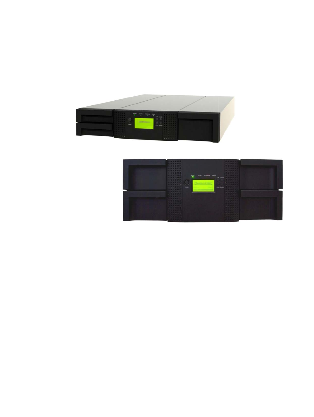
The EditShare 24Q and 48Q Ark Tape Libraries are similar, physically and functionally. The 24Q Ark
Tape Library has the capacity to hold up to 24 LTO tape cartridges and up to two half-height LTO
tape drives in its 2U chassis. The 48Q Ark Tape Library can hold 48 LTO tape cartridges and up to
four half-height LTO tape drives in its 4U chassis.
Chapter 1: Introduction
The Editshare 24Q/48Q Ark Tape Libraries are compa
simple, unattended data backup. When paired with the Editshare Ark Tape Archive application,
users can take full advantage of the many features of these libraries.
Major characteristics of the EditShare 24
• Platform - support for either one to
in a 24Q Tape Library, and one to four drives in a 48Q Ark Tape Library.
• Connectivity - Fibre Channel (FC) and/or Serial Attached SCS
tape drives
• Expandability - additional half-height tape
unused drive slot locations.
• Technology upgrade - tape drive t
LTO-6, etc.)
• Service friendly design - easy access to magazines,
supply for field replacement
• Maximum up time - through advanced error handling and recovery capability
The 24Q/48Q Ark Tape Libraries include the
• USB interface to enable service
customized features (storage on demand) implementation
• The library can be operated via the front operator control panel (OCP), over the network or the
Internet via
connection from the EditShare Ark Tape application
the integral remote management unit (RMU), or via the storage interface
Q/48Q Ark Tape Libraries include:
two half-height LTO-5, LTO-6, LTO-7 or LTO-8 tape drives
echnologies can be upgraded in the field (i.e. LTO-5 to
following features:
ability features (library and drive firmware upgrades) and/or
ct, economical, high-capacity solutions for
I (SAS) depending upon installed
drives may be field-installed in a library that has
tape drives, library controller and power
• Supports industry standard manageme
• The 24Q has one mailslot for import/export of cartridges during library operation while the
48Q has three
• Media changer with barcode reader
•Rack-mounted
mailslots
nt protocols such as SNMP
10 TP-00347-01

Hardware Configuration
Hardware Configuration
The 24Q and 48Q Ark Tape Libraries have the following configurations:
Height: 2U 4U
Number of magazines: 2 (12 slots each) 4 (12 slots each)
Number of mailslots: 1 3
Number of tape slots: 24 (less mailslots) 48 (less mailslots)
Tape Drives: 1 or 2 half-height drives 1 to 4 half-height drives
Power supply: 1 1
Library controller: 1 1
24Q Tape Library 48Q Tape Library
Supported Tape Drives
EditShare 24Q/4Q Ark Tape Libraries were developed to integrate industry-standard IBM LTO
Ultrium tape drives.
Mixed drive generations
The tape drives that have been implemented and qualified f
Libraries are as follows:
• LTO-5 Half-Height FC
• LTO-5 Half-Height SAS
• LTO-6 Half-Height FC
• LTO-6 Half-Height SAS
• LTO-7 Half-Height FC
• LTO-7 Half-Height SAS
• LTO-8 Half-Height FC
• LTO-8 Half-Height SAS
and mixed interfaces are supported.
or use in EditShare 24Q/4Q Ark Tape
TP-00347-01 11
Controls and Indicators
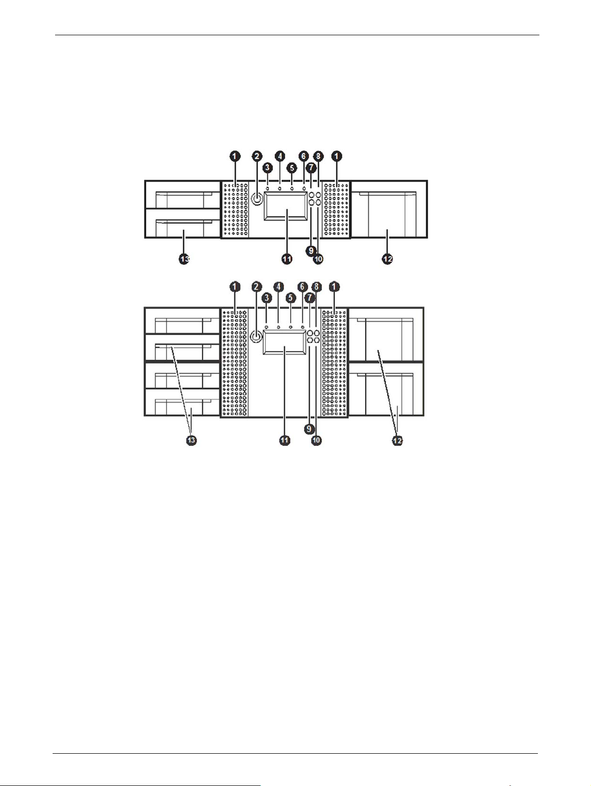
Front Panel
Chapter 1: Introduction
1. Air vents
2. Power button: Pressing the button will initiate a controlled power down of the library (soft
pow
er down)
3. LED <READY> (green): is illuminated during power on
changer activity.
4. LED <CLEAN> (amber): is illuminated when the tape drive has determined that a cleaning
tape sh
cleaning is not necessary.
5. LED <ATTENTION> (amber): is illuminated when th
requires attention by the operator.
6. LED <ERROR> (amber): is illuminated wh
occurs. A corresponding error message is shown on the LCD screen.
7. <UP> button [▲]: is used to na
8.
<CANCEL> button [
9. <DOWN> button [►]: is used t
10. <ENTER> button [ ]: is used to enter to a sub menu or execute an action.
11 Operator control panel (OCP) consisting of a 128
and status information, menu items or error messages relevant to the operational mode.
12 Right magazine(s)
13 Left magazine with mailslot(s)
ould be used. Cleaning is only necessary when the library directs to do so. Additional
en an unrecoverable tape drive or library error
vigate backward through menu items.
X]: is used to cancel a user action and return to the last menu item.
o navigate forward through menu items.
; blinking during tape or library media
e library has detected a condition that
64 pixel screen. The OCP displays actions
x
12 TP-00347-01
Controls and Indicators
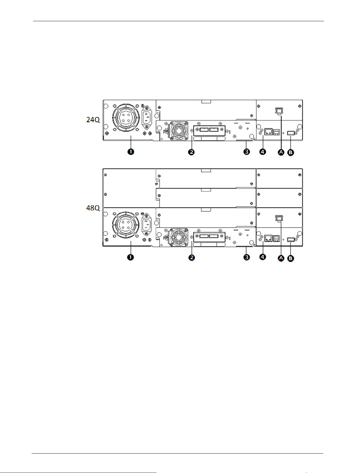
Rear Panel
The rear panels of both tape libraries provide access to the drive interface connectors (either SAS
or Fibre Channel), the power connector, Ethernet, serial and USB ports and the magazine release
holes.
The power supply is on the left side, tape drives are in the middle and the library controller is on
libraries.
the right side of
these
1. Power supply (lower left) A Storage location for shipping lock.
2. Tape drive(s) B USB port (firmware upgrades, key storage)
3. Pull-out tab containing the product
inf
rmation
o
(Serial Number/Model/Customer)
4. Library controller
TP-00347-01 13
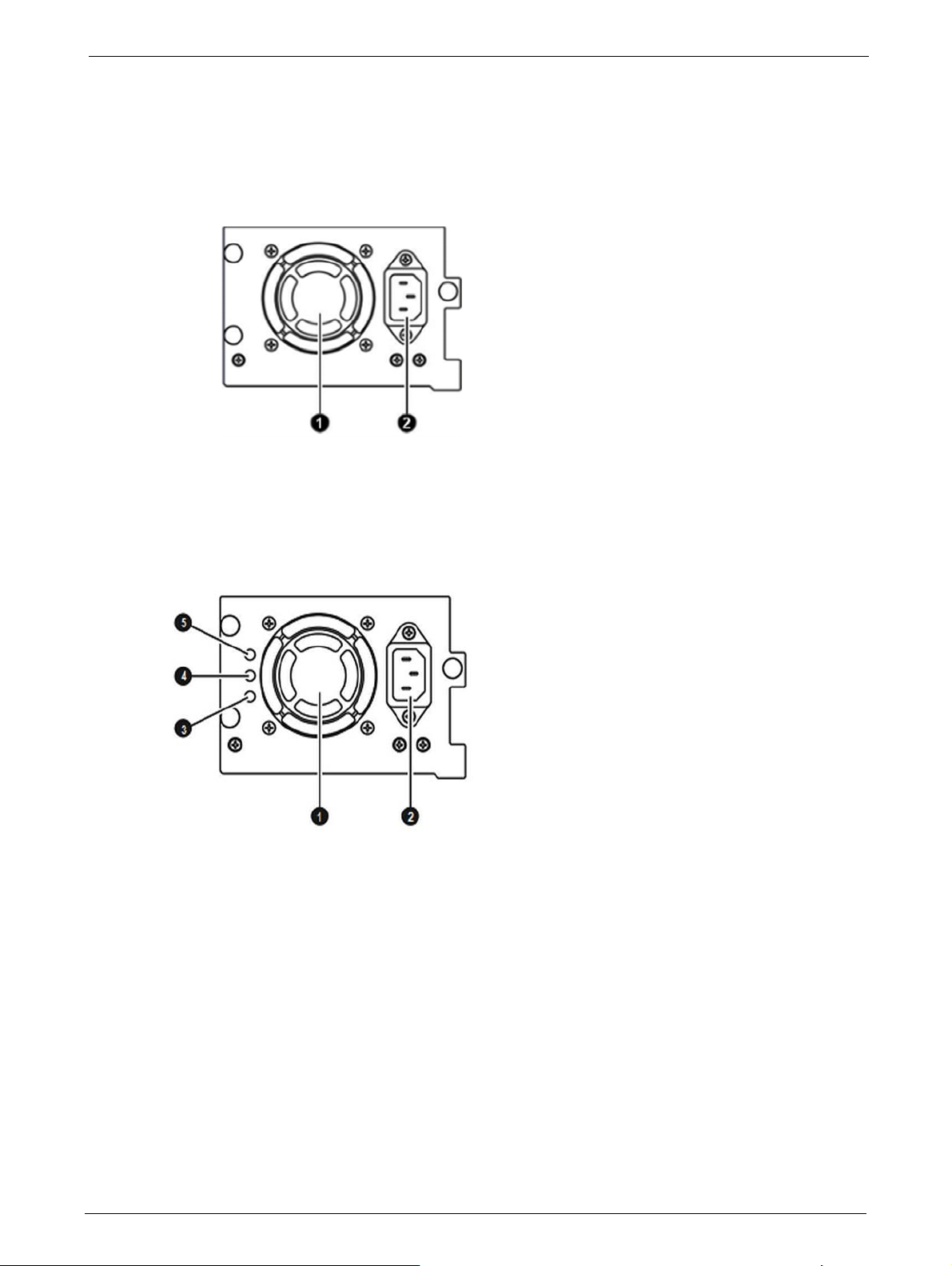
Power Supplies
1. Fan Vent
2. Power connector (110-220 V AC
1. Fan Vent
2. Power connector (110-220 V AC
3. LED (blue) - AC power
4. LED (amber) -Fan Failure
5. LED (green) - Power
24Q Library
Chapter 1: Introduction
48Q Library
14 TP-00347-01
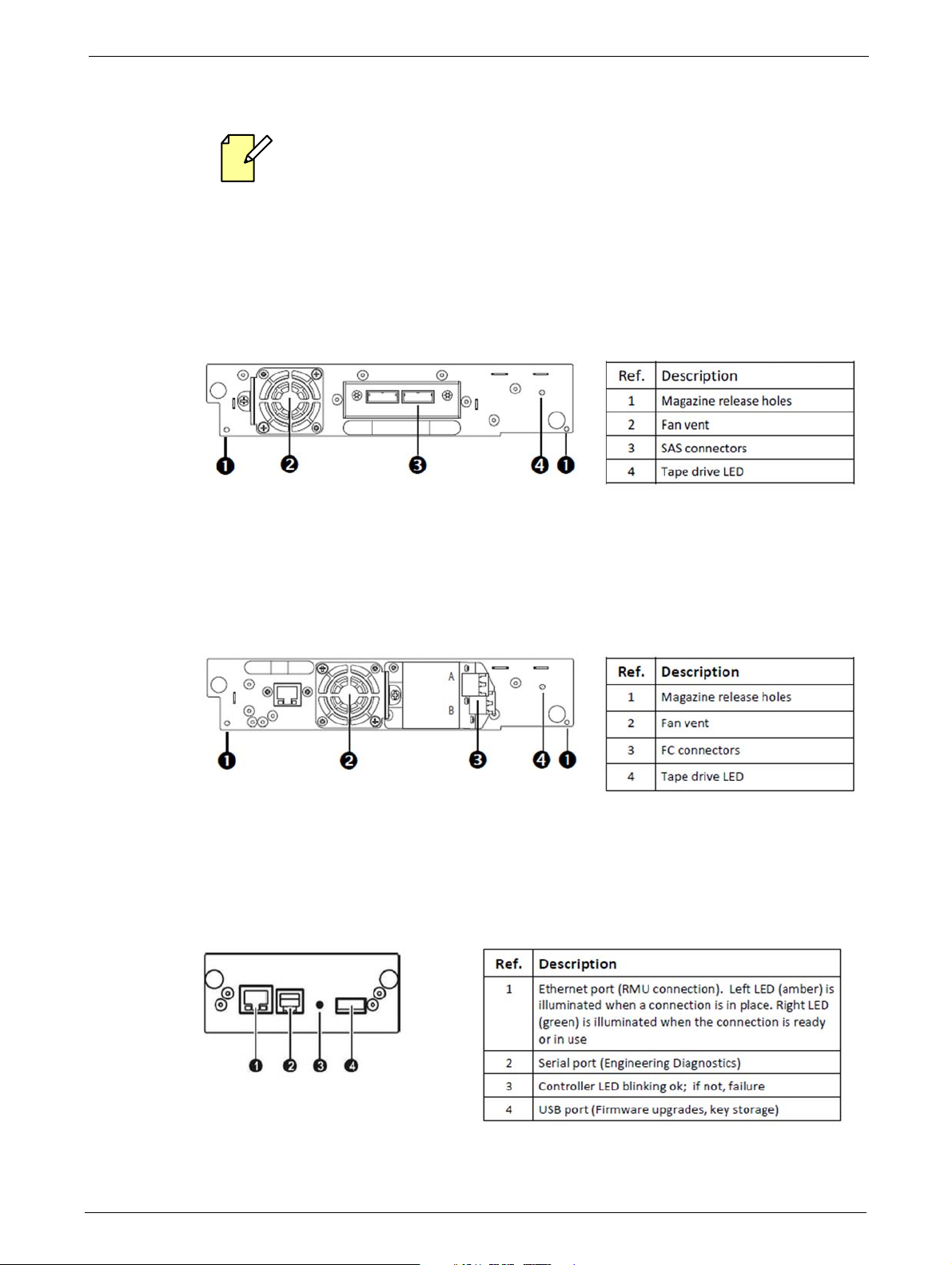
Controls and Indicators
Tape Drive Back Panels
For best performance, use the appropriate HBA for your tape drive. A lower throughput HBA
might result in performance degradation when backing up high
higher throughput tape drive.
In a SAN installation, all switches between the host and the library must be of the
appropriate type. A lower throughput switch
degradation. Configure zoning so only the backup servers may access the library.
IBM LTO-5/6/7/8 HH SAS
ly compressible data to a
in the path may result in performance
FC Half-Height Drive
Library Controller
TP-00347-01 15

Additional Documentation
STEPS
Additional information regarding your EditShare tape library may be found in the following
documents:
• EditShare Ark Setup and User’s Guide
Chapter 1: Introduction
• EditShare Storage
• EditShare Storage
• EditShare
These documents are in PDF format and you can access them
follows:
1. Open your web browser and navigate to the web address for your EditShare server, for
example,
2. On the page that displays, under ‘EditShare Documentation’, click on Manuals.
3. A page opens that displays the available user documentation for your system. Click on the
link corresponding to the document you wish to read.
These documents are also included on the Support USB stick included with the server. If you
cannot find or access your manuals, please contact EditShare Technical Support.
Technical Support
/ Ark Installation Guide and ReadMe
Editor’s Guide
Storage Administrator’s Guide
from the server’s status web page as
http://192.168.0.27
For questions not addressed in our documentation, contact EditShare Technical Support. Have the
exact version number of your EditShare implementation, workstation operating system, and
editing software ready.
EditShare strongly recommends that you purchase
Please contact EditShare Technical Support at the following URL:
http://www.editshare.com/support
Information about new features and bug fixes are
server’s version, the EditShare update web site (http://updates.editshare.com/) or your server’s
Status Page.
a support agreement for your system.
available in the EditShare ReadMe for your
16 TP-00347-01

Chapter 2: Installation
Always observe the Safety Warnings and Cautions described on page 3.
This section provides instruction
following sections:
• "Preparation" on page 18
• "Serial Attached SCSI (SAS
• "Fibre Channel Requirements" on page 19
• "Unpacking" on page 20
• "Installing the Library" on page 22
• "Installing Tape Drives" on page 23
• "Installing the Library Co
• "Power Supply Installation" on page 25
• "Cable Connections" on page 26
s for installing the 24Q and 48Q Ark Tape Libraries. See the
) Requirements" on page 18
ntr
oller" on page 24
TP-00347-01 17
Preparation
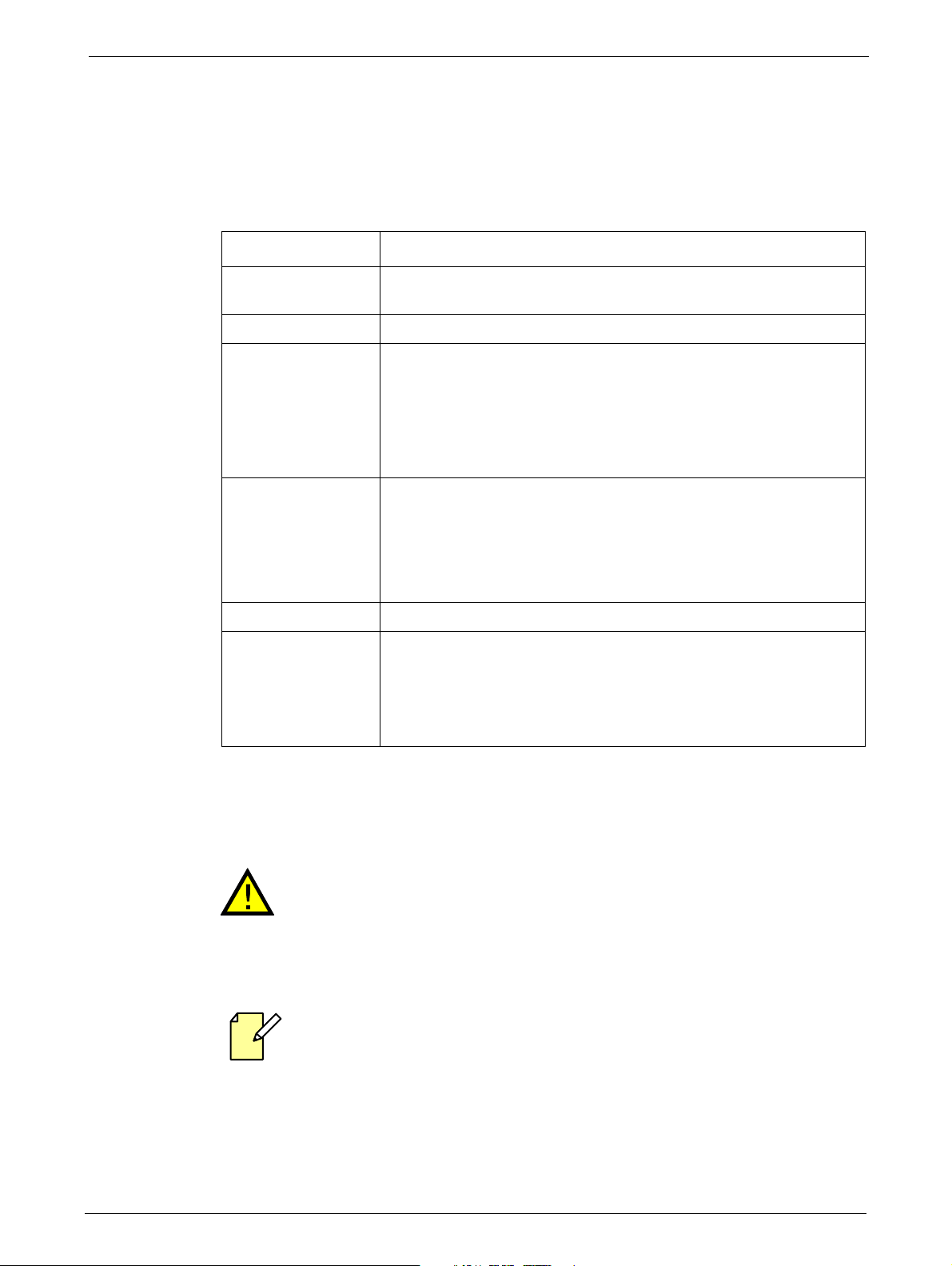
Location Requirements
The 24Q and 48Q Ark Tape Libraries require the following environmental conditions:
Criteria Definition
Rack requirements Standard 19-inch rack with vertical space of 2U available for the Q24 or
Room temperature 10-35°C (50-95°F)
Power source AC power voltage: 100-127 VAC; 200-240 VAC
Air quality Place the library in an area with minimal sources of particulate
Chapter 2: Installation
vert
ical space of 4U available for the Q48.
Line frequency: 50-60 Hz
Place the library near to an AC outlet.
The AC power cord is the library's main AC disconnect device and must
be
easily ac
contamina
cessible at all times.
tion.
Avoid areas near frequently used doors and walkways, stacks of
sup
plies that collect dust, printers, and smoke-filled rooms.
Excessive dust and debris can damage tapes and tape drives.
Humidity 20-80% relative humidity non-condensing
Clearance Back: Minimum of 15.4 cm (6 inches)
Front: Minimum of 30.8 cm (12 inches) - for mailslot
Minimum of 60 cm to remove magazines (24 in)
Sides: Minimum of 5.08 cm (2 in)
For further information, see "Chapter 7: Specifications" on page 103.
Serial Attached SCSI (SAS) Requirements
High quality SAS cables rated at the transfer rate of the SAS drives are required.
Always verify that the SAS cable you are using is rated for the data transfer
of the interface of your components. SAS cables described as "equalized" may
not support 6 Gb/s data rates and should not be used with LT0-5 or later
generation tape drives without first verifying that they are suitable for 6Gb/s
data rates.
speed
The library has a mini-SAS connector on each SAS tape drive. Mini-SAS connectors are
keyed.
Serial Attached SCSI (SAS) is a computer bus technology mainly used to transfer data to and from
storage devices, including disk drives and tape drives. SAS is designed to transfer data at up to 6
gigabits per second.
18 TP-00347-01
Preparation
SAS uses serial connections, with a direct connection between the host server and each of the
storage devices. This eliminates the need to configure SCSI buses and assign SCSI IDs, as was
required for parallel SCSI devices.
The companion Ark Tape server purchased from Editshare will be configured with a compatible
SAS Host Bus Adapter (H
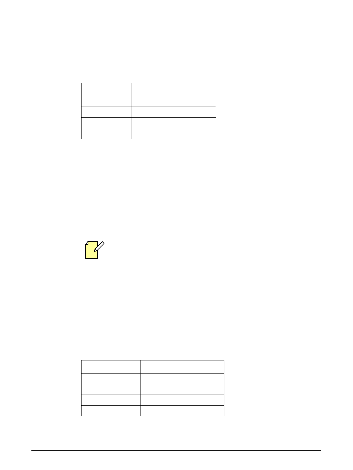
Supported speeds by drive generation are shown in the following table:
LTO G en er a ti on Supported Speeds
LTO - 5 1.5 Gb/s, 3Gb/s, 6Gb/s
LTO - 6 1.5 Gb/s, 3Gb/s, 6Gb/s
LTO - 7 1.5 Gb/s, 3Gb/s, 6Gb/s
LTO - 8 1.5 Gb/s, 3Gb/s, 6Gb/s
BA). Refer to the Ark Setup and User Guide for more information.
A SAS tape drive is identified by a un
Wide Identifier (WWID). The library assigns the WWID to the drive bay. When a tape drive is
replaced, the WWID is re-assigned to the new tape drive.
The operating system tracks the WWID for the tape drive on each HBA channel. Each of the drive
ectors on the fan-out cable is associated with an HBA channel. Once a tape drive has been
conn
plugged in, it should remain on the same channel to retain the association between the HBA
channel and WWID.
Fibre Channel Requirements
For best performance, use the appropriate HBA for your tape drive. A lower throughput
HBA might result in performance degradation
to a higher throughput tape drive.
In a SAN installation, all switches between the host and the library
appropriate type. A lower throughput switch in the path may result in performance
degradation. Configure zoning so only the backup servers may access the library.
The Fibre Channel tape drive can be connected directly to the server with a host bus adapter (HBA).
The installation requires one Fibre Channel cable for ea
LC-style connector. Some drives will have two FC ports, but only one cable connection is needed
per drive. The cable can be connected to either drive FC port.
identifier called a World Wide Name (WWN) or World
ique
when backing up highly compressible data
must be of the
ch tape drive. The tape drives all utilize an
The companion Ark Tape server purc
Host Bus Adapter (HBA). Refer to the Ark Setup and User Guide for more information.
Supported speeds by drive generation are listed in the following table:
LTO G en er a ti on Supported Speeds
LTO - 5 2 Gb/s, 4 Gb/s, 8 Gb/s
LTO - 6 2 Gb/s, 4 Gb/s, 8 Gb/s
LTO - 7 2 Gb/s, 4 Gb/s, 8 Gb/s
LTO - 8 2 Gb/s, 4 Gb/s, 8 Gb/s
TP-00347-01 19
hased from Editshare will be configured with a compatible FC

Unpacking
STEPS
Unpacking the Library
Chapter 2: Installation
If the temperature in the room where the library is to be installed varies by 15°C
(30°F) or more from the room where the libra
acclimatize to the surrounding environment for at least 12 hours before
unpacking it from the shipping container.
ry was stored, allow the library to
Do not place the library on either the end or sides as this
Before unpacking the library, clear a work surface on
the library is to be installed in a rack, select an open rack location allowing easy access to the host
server and an easily accessible power outlet.
1. Before opening and removing the tape library from the box, inspect the container for
shipping damage. If you notice any damage, report it to the shipping company immediately.
2. Open the box.
3. Carefully remove the shipping materials from the top of
4. Remove the accessory package and set a
5. Remove the two rack rails and set a
6. Lift the library out of the carton and remove the bag from the loader. Save the packaging
materials for future use.
Identifying Product Components
Confirm that you received the following:
may damage the unit.
which to place the unpacked components. If
the library.
side (if included).
side (if included).
1) 24Q/48Q Ark Tape Library, including:
• 1 x Power Supply,
• 1 or more half-height T
• 1 x Library controller
• 2 x Tape magazines for the 24Q - or:
4 x Tape magazines for the 48Q
2) Rack mount kit comprising:
• 2 x Rack Mount Rails
• 1 x Bag of eight M6 screws for the rack m
column)
• 1 x Bag of eight M6 screws for rack mounting
column)
3) Power cord
4) Library documentation
Optional components, depending on the purchased configuration:
• Cables - Fibre Channel or
20 TP-00347-01
SAS cables
pe drives (as ordered)
a
o
unting (9.5 mm square holes in the rack
(6.85 mm round holes in the rack
Unpacking
STEPS
24Q
48Q
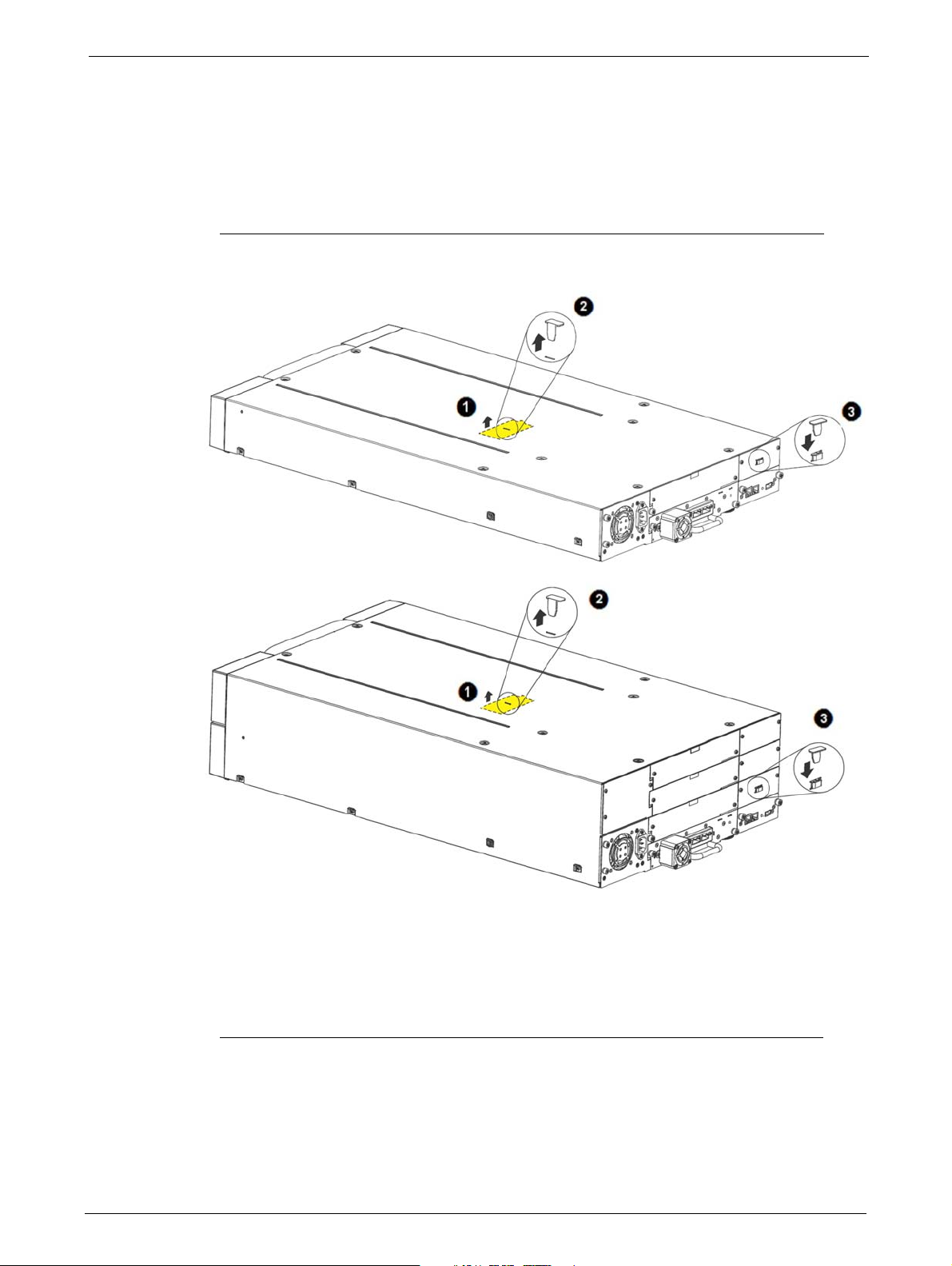
Removing the Shipping Lock
The Shipping Lock, which prevents the media changer transport mechanism from moving
during shipment, must be removed before the library is powered on.
To remove and store the shipping lock:
1. Remove the yellow label that is securing the shipping lock on the top of the
library.
2. Remove the shipping lock.
3. Store the shipping lock in the slot provide
library is to be returned or transported to a new location at some future time.
4. Replace the yellow label on the top of the library.
TP-00347-01 21
d on the rear panel - The Lock is required if the
Installing the Library
STEPS
Tools Required
The following tools are required to install the library:
•No. 3 Phillips screwdriver
• T10 Torx screwdriver
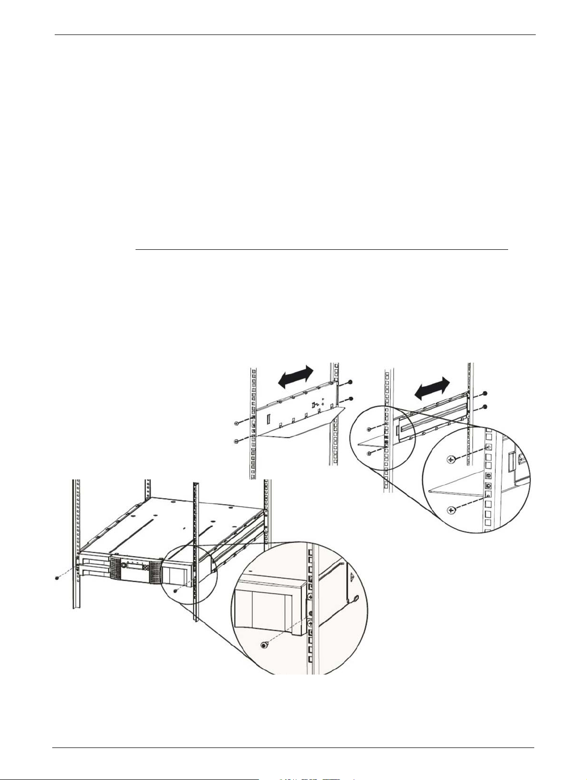
Rack-Mounting the Library
To rack mount the library:
1. Determine the location in which the library rack is to be installed.
2. Use a pencil to mark the location on each vertical rail in the rack.
Chapter 2: Installation
3. In the rack mount kit are two sets of eight M6 sc
choose the appropriate type of M6 screws.
4. Secure one rail to each side of the rack in your chosen rack location with a #3 Phillips
screwdriver. I
nsure the rails are mounted level and at the same rack height on each
rews. Determine the type of rack then
side.
5. Secure both the front and back of each
22 TP-00347-01
rack rail to the rack.
Installing Tape Drives
STEPS
6. Slide the library onto the rack rails.
7. Secure the library to the rack using a No 3 Phillips screwdriver placed through the small
holes in the mounting bracket to tighten the M5 screw(s) on each side of the library.
Installing Tape Drives
Tape drives are installed from the rear of the library. If the library does not already have a tape drive
installed, install it now. If the library already has one tape drive installed, additional tape drives may
be added now or after installation of the library is complete.
Tools Required
The following tool is required:
•No 2 Phillips screwdriver
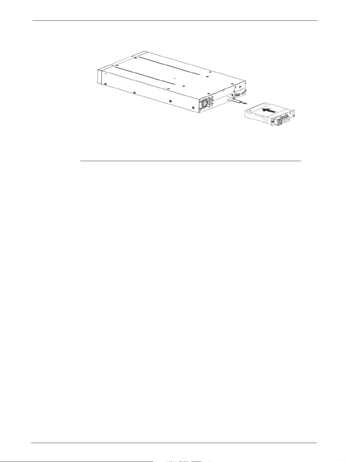
Installation Procedure
To install tape drives:
1. The 24Q has space for two half-height tape drives, and the 48Q has space for four half-height
tape drives. Always install the first tape drive in the bottom of the drive bay. A drive bay
cover must be installed over any empty drive positions.
2. If a drive cover is present, loosen the screws and remove the cover to install one half-height
tape drive.
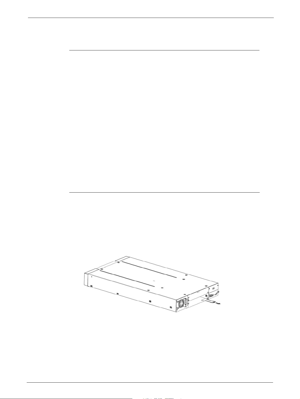
3. When installing the bottom drive, slightly pull out the tab of the product ID label so it does
not interfere with the inse
rtion or removal of the
tape drive.
4. Before installing the drive, inspect th
intact, free of any foreign objects, and have no cracks, or deformed or bent contacts.
TP-00347-01 23
e connectors on it. Ensure that the connectors are
Chapter 2: Installation
5. Insert the tape drive into the drive bay, and align the connectors on the library while
supporting the
drive.
6. Push the tape drive into the drive bay until the tape
library. If extended, push the tab for the product ID label back into the library.
7. Tighten the blue captive screws with your fingers to secure the tape drive to the library.
Installing the Library Controller
The library controller is installed from the rear of the library. If the library does not already have a
library controller installed, install it now.
Tools Required
The following tool is required:
•No 2 Phillips screwdriver
drive seats itself against the back of the
24 TP-00347-01
Power Supply Installation
STEPS
Installation Procedure
To install tape drives:
1. Locate the vacant library controller bay on the lower right side of the rear panel.
2. If present, loosen the screws and remove the library controller bay cover.
3. Before installing the library controller, inspect its connectors. Ensure that the connectors are
intact,
free of any foreign objects, and have no cracks or deformed or bent contacts.
4. Insert the library controller on the alignment rails and push it into the
against the back of the
5. Tighten the blue captive screws with your fingers to secure the library controller.
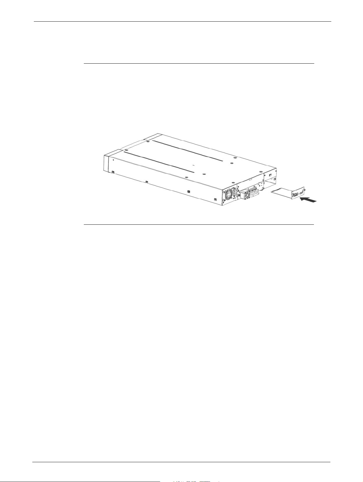
Power Supply Installation
The power supply is installed from the rear of the library. If the library does not have a power supply
installed, install it in the left power supply bay now.
bay until it seats itself
library.
Tools Required
The following tool is required:
•No 2 Phillips screwdriver
TP-00347-01 25
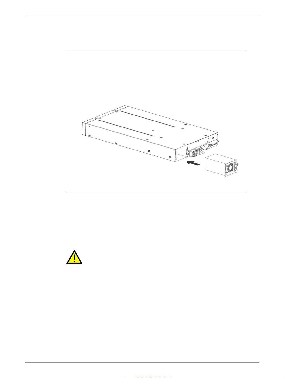
Installation Procedure
STEPS
To install a power supply:
1. Locate the power supply bay on the lower left side of the rear panel of the library.
2. If present, loosen the screws and remove the power supply bay cover.
3. Before installing the power supply, inspect its connectors. Ensure that the connectors are
intact,
Chapter 2: Installation
free of any foreign objects, and have no cracks or deformed or bent contacts.
4. Insert the power supply on the alignment rails and push it into the
against the back of the
5. Tighten the blue captive screws with your fingers to secure the power supply to the library.
Cable Connections
bay until it seats itself
library.
Power Cord Connections
Mains voltages are present on this equipment. Before connecting a power cord
to the library:
Ensure that the power cord meets safety standards for
equipment is installed.
Use cable rated at 13A to avoid overheating the cord.
Always observe the Safety Warnings and
To connect the powe
26 TP-00347-01
r cord to the library:
Cautions described on page 3.
the country where the
Cable Connections
STEPS
STEPS
STEPS
1. Plug the female connector of the power cord into the power connector (AC connector) on
the rear panel of the power supply.
• For 24Q power supplies, refer to the diagram "24Q Library" on page 14.
• For 48Q power supplies, refer to the diagram "48Q Library" on page 14.
2. Plug the male connector into an appropriate electrical socket.
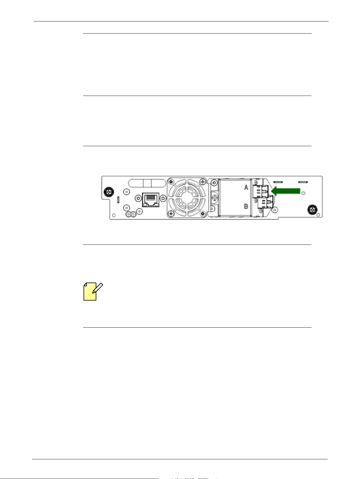
Connecting Fibre Channel Cables
To connect the fibre channels:
1. Remove the FC port caps if necessary. Attach one end of the FC cable to port A on the tape
drive.
2. Attach the other end of the FC cable to the HBA installed in your EditShare Ark Tape server.
Refer to the EditShare Ark Setup and User’s Guide for additional information.
Connecting SAS Cables
SAS signal rates require clean connections between the HBA and tape drive. Do not use
adapters or converters between the HB
maximum SAS cable length of six meters.
To connect the SAS cables:
1. Attach the HBA end of the SAS cable into the connector on the HBA. If you are using a SAS
fanout
the HBA.
A and the tape drive. For reliable operation, use a
/ Hydra cable, the end of the cable with only one connector should be plugged into
TP-00347-01 27
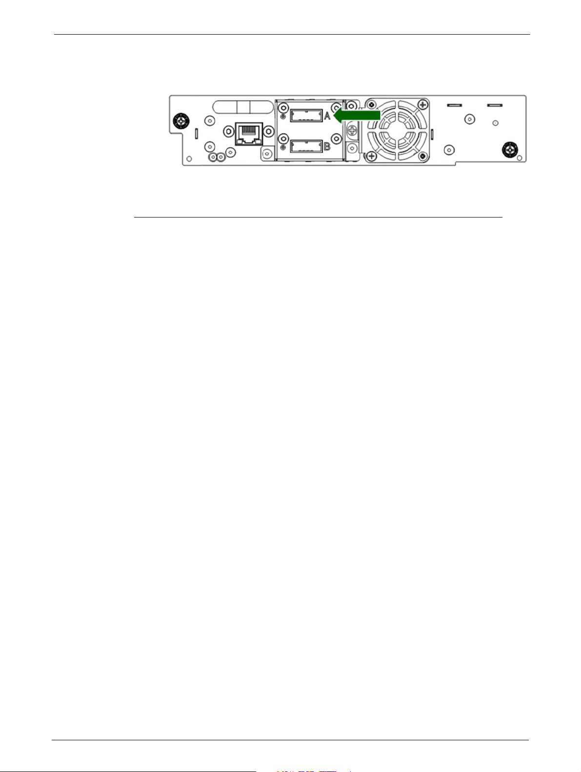
2. Connect the drive end of the cable:
Chapter 2: Installation
• If you are using a cable with a single connector on each end, attach the
connector on the
• If you are using a SAS fanout/Hydra cable, attach one mini-SAS connector into the
nnector on each tape drive. Coil and secure any unused fanout cables to the rack to
co
minimize stress on the cables and connectors.
Connecting an Ethernet Cable
The connection to the Ethernet network is via an industry standard RJ45 copper interface on the
rear panel of the library. The Ethernet connection is used to access the library RMU over a network.
To connect the library to the Ethernet network,
the library. When the plug is in the correct position, a click should be heard.
other end into the
tape drive.
insert the Ethernet cable into the Ethernet port of
Connecting a USB device
The USB port is on the rear of the library. It can be used for firmware upgrades/skin file updates
initiated via the Operator Control Panel (OCP).
28 TP-00347-01

Chapter 3: Cartridges and Magazines
This chapter explains which media to use with your library, and how to label and write-protect your
tape cartridges. Careful labeling and handling of the tape cartridges prolongs the life of tape
cartridges and the library.
See the following sections:
• "Use and Care of Tape Cartridges" on page 29
• "Supported Cartridge Types" on page 30
• "Labeling Tape Cartridges" on page 30
• "Write Protecting Tape Cartridges" on page 31
• "Read/Write Compatibility" on page 32
• "Magazines" on page 32
Use and Care of Tape Cartridges
DO NOT degauss LTO data cartridges. These data cartridges are prerecorded with
a magnetic servo signal. This sign
tape drive. Keep magnetically charged objects away from the cartridge.
al is required to use the cartridge with the LTO
Do not place data cartridges near sources of electro
magnetic fields such as computer monitors, electric motors, speakers, or X-ray
equipment. Exposure to electromagnetic energy or magnetic fields can destroy
data and the embedded servo code written on the media by the cartridge
manufacturer, which can render the cartridge unusable.
Clean drives with Ultrium Universal cl
To ensure the longest possible life for your data cartridges, follow these guidelines:
• Use only the data cartridges designated for your device.
• Clean the tape drive when the Clean drive LED is illuminated.
Do not drop a cartridge. Excessive shock can damage the internal contents of the
cartridge or the cartridge case itself
Do not expose data cartridges to direct sunlight
portable heaters and heating ducts.
The operating temperature range for data cartridges is
temperature range is +40°C to 60°C in a dust-free environment in which relative
humidity is always between 20% and 80% (non-condensing).
If the data cartridge has been exposed to temperatur
ranges, stabilize the cartridge at room temperature for the same length of time it
was exposed to extreme temperatures or 24 hours, whichever is less.
eaning cartridges only.
, making the cartridge unusable.
magnetic energy or strong
or sources of heat, including
10 to 35º C. The storage
es outside the specified
Place identification labels only
TP-00347-01 29
in the designated area on the cartridge.
Supported Cartridge Types
Use the Ultrium data and cleaning tape cartridges designed for the tape drive formats present in
your library.
Tape Drive Cartridge Type
LTO - 5 LTO -5 U ltr i um D ata C art rid g e
LTO - 6 LTO -6 U ltr i um D ata C art rid g e
LTO - 7 LTO -7 U ltr i um D ata C art rid g e
LTO - 8 LTO-8 and LTO-7 Type M Ultrium Data Cartridge
- Ultrium Universal Cleaning Cartridge
Chapter 3: Cartridges and Magazines
Labeling Tape Cartridges
Neither the EditShare Ark Tape application nor the tape library support unlabeled media.
Make sure every cartridge has a barcode label in place.
Misusing and misunderstanding bar code technology can result in backup and
failures. Use only high quality labels. Self-printed labels are not recommended as they are
often a source of barcode reading issues.
The device contains a bar code reader that reads the tape labels and stores the inventory data in
memory. The device then provides the inventory information to the host application, OCP, and
RMI. LTO tape cartridges must have barcode labels in order for the EditShare Ark Tape application
to work as designed.
A proper bar code label includes the media ID in the last two characters of the bar code. The library
will not load an incompatible cartridge, based on the
example, the library will not load a cartridge labeled as LTO-3 into an LTO-6 tape drive. This saves
the time needed to load the cartridge and have the tape drive reject it.
EditShare Ark Tape keeps track of the
• Date of format or initialization
• Media pool to which the tape belongs
•
Data residing on the tape
restore
barcode media ID, into a tape drive. For
following information via the associated bar code:
•Age of the backup
• Errors encountered while using
30 TP-00347-01
the tape (to determi
ne if the tape is faulty)

Write Protecting Tape Cartridges
STEPS
LTO tape cartridges have a recessed area located on the face of the cartridge next to the
write-protect switch. Use this area for attaching the adhesive-backed bar code label. Only apply
labels as
shown:
The bar code label should only be
of the tape cartridge. Never apply multiple labels onto a cartridge because extra labels can cause the
cartridge to jam in a tape drive.
applied as shown, with the alphanumeric portion facing the hub side
Write Protecting Tape Cartridges
All rewriteable data cartridges have a write-protect switch to prevent accidental erasure or
overwriting of data. Before loading a cartridge into the device, make sure the write-protect switch
on the front of the cartridge is in the desired position.
1 Insertion Arrow
2 Barcode Label
3 Write-Protect Switch
4 Write-Protected
5 Write-Enabled
1. Slide the switch (3) to the left to allow the device to write data to the cartridge.
2. Slide the switch to the right to write-protect the cartridge. An indicator, such as a red mark
or small padlock, is visible showing that the cartridge is write-protected.
TP-00347-01 31

Chapter 3: Cartridges and Magazines
Read/Write Compatibility
The following table summarizes the Read/Write compatibility of the Ultrium LTO drives:
LTO - 3 D riv e LT O -4 D riv e LT O -5 D ri ve LTO -6 Dr iv e LT O -7 D ri ve LTO -8 Dri ve
LTO -3 M edi a Read/Write Read/Write Read-Only Incompatible Incompatible Incompatible
LTO -4 M edi a Incompatible Read/Write Read/Write Read-Only Incompatible Incompatible
LTO - 5 Me d i a Incompatible Incompatible Read/Write Read/Write Read-Only Incompatible
LTO -6 M edi a Incompatible Incompatible Incompatible Read/Write Read/Write Incompatible
LTO -7 M edi a Incompatible Incompatible Incompatible Incompatible Read/Write Read/Write
LTO -8 M edi a Incompatible Incompatible Incompatible Incompatible Incompatible Read/Write
LTO -7M Med ia Incompatible Incompatible Incompatible Incompatible Incompatible Read/Write
Magazines
Slot Usage
All listed media is incompatible with LTO-1 and
The Ark Tape Libraries make use of removable magazines. Tape cartridges are stored in the
magazines. Each magazine can be individually removed, or inserted. Each magazine inserted in the
library, is locked into position, to prevent unauthorized removal. Access to unlock the magazines
can be password protected. For safety reasons, removal of a tape magazine disables media
changer motion.
The magazines can be unlocked via the Operator Control Panel (OCP) or the Remote Management
Unit (RMU).
•OCP, see "Operator Control Panel (OCP)" on page 33
•RMU, see "Servicing a Magazine" on page 75
In case the OCP or RMU initiated process fails or
emergency release is available, see "Emergency Release" on page 84.
TO-2 drives.
L
the library no longer has power, a manual
Each magazine contains four slots for tape cartridge storage. However, the front slot in the
left-hand magazine can function as a ‘mailslot’.
The mailslot is used to import/export individual ta
operation. The command to open the mailslot may be denied if the media changer is busy with
some operation. In that case, "Busy" is displayed on the OCP and the command has to be repeated
once the media changer operation is finished.
32 TP-00347-01
pe cartridges without interrupting the library

Chapter 4: Operation
STEPS
See the following sections:
• "Powering the Library Up or Down" on page 33
• "Operator Control Panel (OCP)" on page 33
• "Remote Management Unit (RMU)" on page 44
• "Operations" on page 61
• "Partitioning the Library" on page 66
• "Default Settings" on page 69
Powering the Library Up or Down
To power the library up or down:
1. Press the power button on the front panel of the 24Q or 48Q Tape Library.
2. Powering up can take a few minutes because it includes scanning the inventory and
configuration (for example, how many and what type of drives are installed).
Operator Control Panel (OCP)
Operating Modes
The OCP operates in two basic modes:
• User interaction mode: This mode is employed wh
operating panel.
• System driven mode: This is the nor
status associated with the actions that were caused from commands issued from the EditShare
Ark Tape application. Actions like loading, rewinding or moving tape cartridges will be
displayed.
Whenever an operating button is pressed and released, the operating panel automatically
tions to user interaction mode. The user interaction mode will be active until 3 minutes after
transi
the user stops pushing buttons, or the requested media changer activity stops - whichever is
longer. At this time, the operating panel will return to the system driven mode.
en a user is pushing buttons on the
mal mode of operation. In this mode, the OCP displays
In the event that the administrator-programed user security feature is
mode is restricted to the information and login menu screens, until a login with correct PIN is
entered.
TP-00347-01 33
in use, the user interaction

OCP Rules
Chapter 4: Operation
OCP commands obey the following basic rules:
1) Any operational conflict between commands received from the host interface or RMU and
th
ose entered via the front panel will be avoided with a reservation mechanism on a
'first-come, first-served' basis.
Any reservation by OCP is cancelled by an OCP logout or timeout, which cancels the User
eraction Mode.
Int
2) The library firmware will not allow a user to select an impossible request. Those situations
include, but are
• Moving a tape cartridge from any source to a full magazine slot
not limited to:
3) Any error detected by the library or drive controller and not recoverable through predeter-
4) Numeric error codes are only used for unrecoverable, fatal errors (see "Main Error Codes" on
Power-Up Display
When the library powers up or resets, it goes through internal processes that initialize and prepare
the unit for normal operation. These processes are called Power-On-Self-Test (POST). While the
POST is in process, the OCP will display appropriate information to keep the user informed. When
the library finishes POST, it displays the current library status for a defined time or until a front panel
key is pressed.
After this initial status screen, the
screen shows the overall health of the library, indicating the status of the media changer and the
connected drives.
• Moving a tape cartridge from an empty magazine
• Loading a tape cartridge from any so
• Unloading a tape cartridge from an empty tape drive
mined firmware algorithms will be considered as fatal. An error code displays on the OCP
an
d the error LED illuminates. The error code remains on the OCP until a button is pressed,
which causes the OCP to return to the home screen.
page 89), otherwise text status messages are provided.
home screen will be displayed until any key is pressed. The home
urce to a full tape drive
slot
LEDs
All LEDs are updated during power up and reset sequences. Upon power up or software reset, the
library illuminates all LEDs at some point during the POST process. This helps the user to verify
whether all LEDs are functional. When initialization starts, all LEDs are extinguished and the
ready/activity LED flashes at approximately two-second intervals. When the mechanical
initialization is complete, the ready/activity LED stops flashing and remains constantly illuminated.
If a library failure occurs, the ready/activity LED is turned off and the error LED illumina
also displays a specific error code to help identify the failure.
The following are additional operational details regarding the LEDs:
• The <Ready/Activity> LED illuminates any time the unit is powered
successfully completed the POST). The LED blinks whenever there is any tape library or drive
activity. The LED also blinks when the unit is offline.
34 TP-00347-01
on and functional (i.e.
ted. The OCP

Operator Control Panel (OCP)
• The <Clean> LED is only lit when a 'cleaning required' has been issued by one of the drives. The
LED is turned off after a successful drive cleaning operation is performed to the requesting
drive.
Input Modes
Selectable Predefined Values
Toggle Values
• The <Media Attention> LED indicates that there is a piec
or invalid. The LED clears when all such cartridges have been exported from the tape library.
• The <Error> LED illuminates when t
failure. This occurs simultaneously with the hard error message displayed on the screen - the
LED remains illuminated until the error state is resolved.
There are several modes for entering values in the different menu items. These values may be
selectable predefined values, toggle values (e.g. on/off) or numerical values like network
addresses.
After navigating to the menu item, the various predefined values can be selected with the
<DOWN> and <UP> buttons. As soon as the display shows the desired value, it may be confirmed
by pressing the <ENTER> button.
here is an unrecoverable (i.e. hard) drive or tape library
e of LTO media which is bad, marginal
Toggle values are used to switch between two different states like 'on' and 'off'. After navigating to
the menu item the display shows its current state. Pressing the <ENTER> button will select the
item, whose value may then be toggled using the <UP> and <DOWN> buttons. Pressing <ENTER>
again sets the item to the displayed value.
Numerical Values
Numerical values are needed for network addresses, PIN entries, and other configuration entries.
After navigating to the menu item to be changed, the actual value will be displayed and the cursor
stays on the first digit. The value may be incremented / decremented with the <DOWN> and <UP>
buttons. After pressing the <ENTER> button to select the displayed value, the cursor moves to the
next editable digit. Each digit can be changed in the same way. After pressing the <ENTER> button
at the last digit, the complete entry will be stored. Pressing the <CANCEL> button will cancel the
whole edit process and the old value will be restored.
TP-00347-01 35

Power-Down
Chapter 4: Operation
The shutdown process may be aborted by pressing the Cancel button within the first three
seconds.
Pressing the Power button on the library while it is operational will initiate a controlled power
down.
The following operations will take place before the unit shuts down completely:
• The display indicates with an appr
• The library controller finishes all ongoing loader an
• The media changer is moved to its home position.
• The library controller switches off the power supply's secondary side.
Menu Flow Charts (OCP)
See the following sections:
• "Main Menu" on page 37
• "Information Menu" on page 38
• "Commands Menu" on page 40
• "Configuration Menu" on page 41
• "Service Menu" on page 42
opriate message that the shutdown is in progress.
d drive activities.
36 TP-00347-01
Operator Control Panel (OCP)
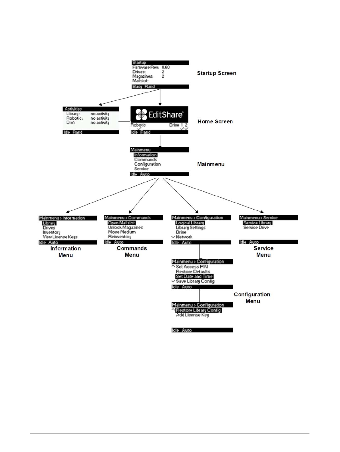
Main Menu
Main Menu
TP-00347-01 37

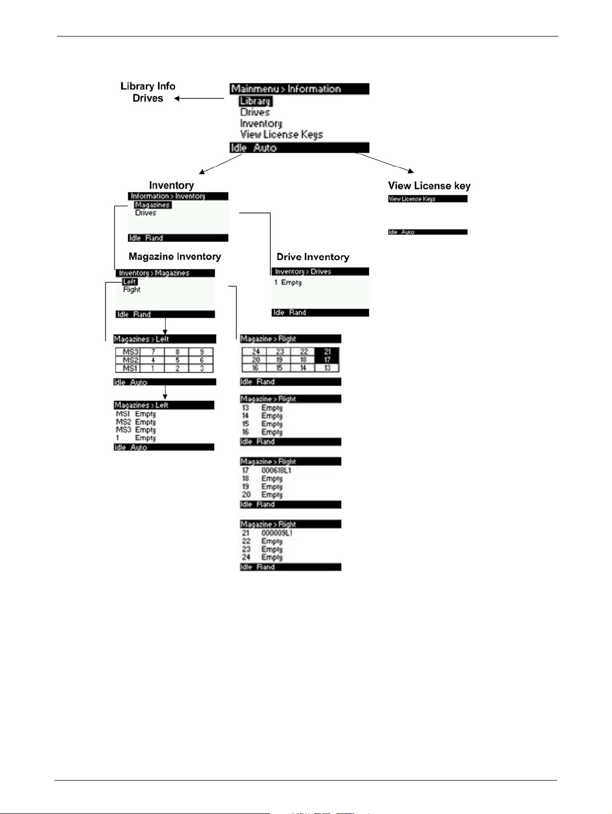
Information Menu
Chapter 4: Operation
Information Menu (1 of 2)
38 TP-00347-01
Operator Control Panel (OCP)
Information Menu (2 of 2)
TP-00347-01 39
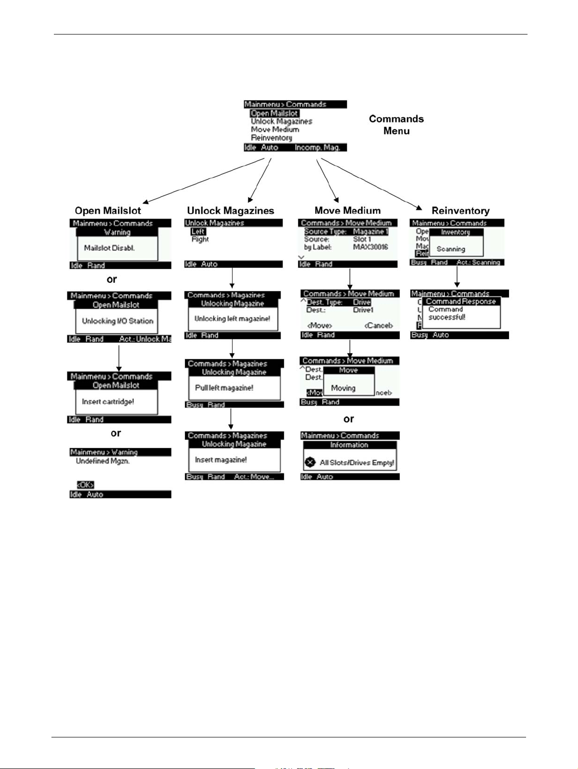
Commands Menu
Chapter 4: Operation
Commands Menu
40 TP-00347-01
Operator Control Panel (OCP)
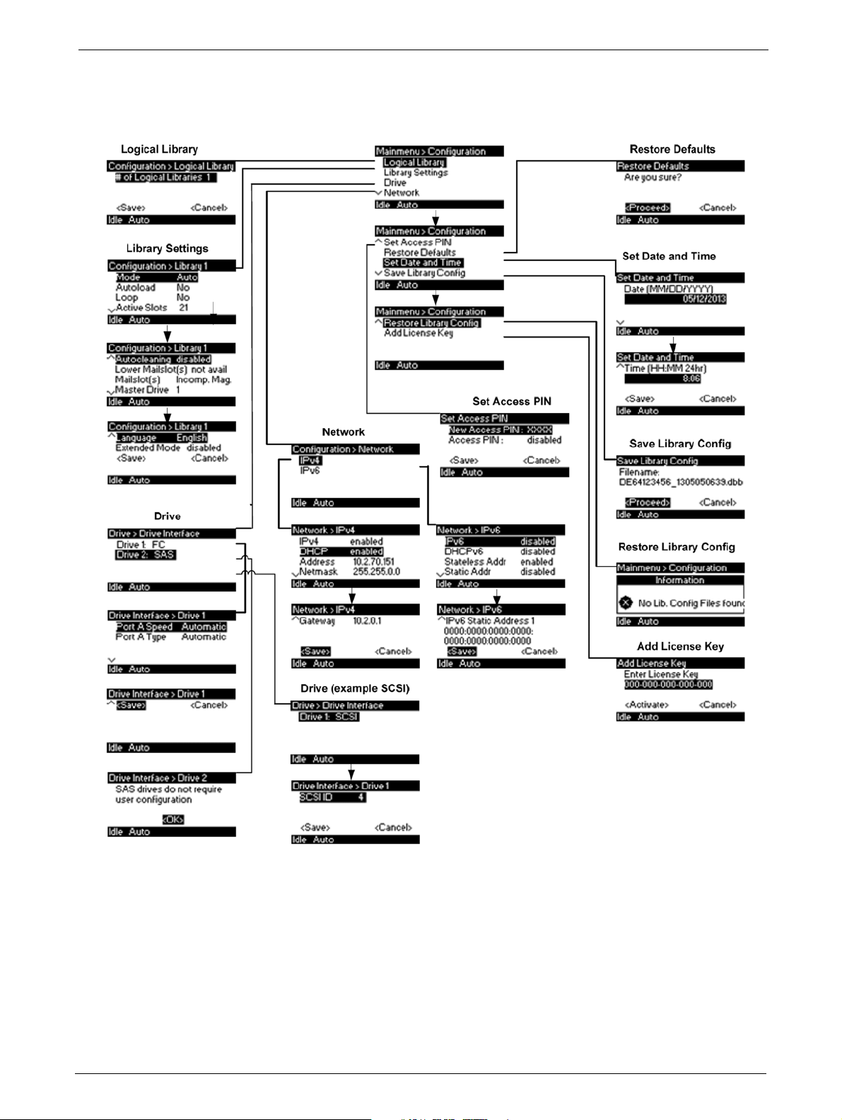
Configuration Menu
Configuration Menu
TP-00347-01 41

Service Menu
Chapter 4: Operation
Service Menu (1 of 2)
42 TP-00347-01

Operator Control Panel (OCP)
Service Menu (2 of 2)
TP-00347-01 43

Remote Management Unit (RMU)
Overview
Many of the same operations performed locally from the operator control panel (OCP) can also be
performed remotely using the network connected Remote Management Unit (RMU).
The RMU lets you monitor and control the library from any computer connected to your network
or
through the World Wide Web (WWW). The RMU hosts a dedicated, protected Internet site that
displays a graphical representation of the library.
Chapter 4: Operation
After establishing a network connection to the libr
address of the library. To allow access from the RMU, you must first set the desired static IP address
at the OCP or configure to use DHCP.
Operation Modes
The following operations are available through the remote management unit as explained below:
1) Identity
2) Status
3) Configuration
ary, open any HTML browser and enter the IP
• Viewing the static library identity
• Viewing the static drive identity
• Viewing the network identity
• Viewing the dynamic library status
• Viewing the dynamic drive status
• Viewing the tape cartridge inventory
• Changing the system configuration
• Changing the logical library configuration
• Setting the license key
• Changing the drive configuration
• Changing the network configuration
• Changing the SNMP configuration
• Changing the user password
• Setting date/time
• Setting error log mode
• Setting event for email no
• Restoring factory defaults
4) Operations
• Move media within the library
• Rescanning the media inventory
44 TP-00347-01
tification parameters

Overview
Model NameAction Bar
Object Bar
Details
Login
• Releasing magazines for removal
5) Service
• Performing a general diagnosis of the library
• Determining and updating firmware
• Reboot of the library
• Viewing library logs
• Cleaning tape drive(s)
•Cartridge memory
Some options of the RMU take the library offline. This inactive mode can interfere with
EditShare Ark Tape, causing data loss. Make sure the library is idle before attempting to
perform any remote operations that will take the library offline.
To login, select the access type and enter the correct password. There are three levels of access:
• Guest - (standard user level - default password
std001).
• Admin - (administrator user level - default password
adm001).
• Service - (service user level; for access by service
personnel only - default password ser001).
Each level affects the areas to which you have access and
what actions you can initiate in those areas.
RMU Screen Layout
Once logged in, the general layout of all RMU screens is similar:
Menu items in the Action bar and Object bar are selectable, and the currently selected item is
displayed in bold italics. The items listed in the Action bar are fixed, but the items in the Object bar
vary according to the action selected (see "Operating Modes" on page 33). Similarly, the contents
of the detailed information area shown below the two bars depend on the selected action and
object.
TP-00347-01 45

Chapter 4: Operation
At the right side of every screen, a summary of the
system status is displayed and continually updated:
The status icons that may be displayed are as
follows:
The information displayed is as follows:
Date/Time
Status: Overall library status
Drive Status: Individual drive status (there will be one entry for each installed drive).
Slots (Free/Total): Total library slot capacity
Mailslot: Open/Closed
Library Time: Time stamp displayed in 24 hour format
Auto Clean Status: If Auto Clean Option is configured, its status displays here
Identity
Viewing Static Library Identity
This page provides access to the static information about the system. No changes can be made
from this page.
46 TP-00347-01

Overview
The following information displays:
1) Library Information
• Serial Number
•Product ID
• Currently installed library firmware
• Boot code firmware revision
•Barcode Reader
• Library Mode
• World Wide Node Name
2) Extended logical library information: If the unit has more than one partition, the properties
of each logical library display as above.
Viewing Static Drive Identity
This page provides access to the static information about the drive(s). No changes can be made
from this page.
If two tape drives are installed in the library, the information will be shown by selecting the
appropriate drive from the pull down menu.
The following information is displayed:
1) Drive information:
• Vendor ID = Drive manufacturer
• Product ID = Model identification of the drive
• Serial Number = Serial number of the drive
• Firmware Revision = Operating firmware level of the drive
• Physical Drive Number = Number indicating drive's physical position within the library
• Element Address = Number indicating the logical identification of the drive
• Library Master Drive = Indicates if library's logical interface is hosted by this drive
• Data Compression = Indicates if drive hardware data compression is enabled
• Interface Type (SAS or FC) = Indicates drive's physical interface connection type
2) Additional drive information (up to 4 x half-height tape drives for the Q48)
TP-00347-01 47
Chapter 4: Operation
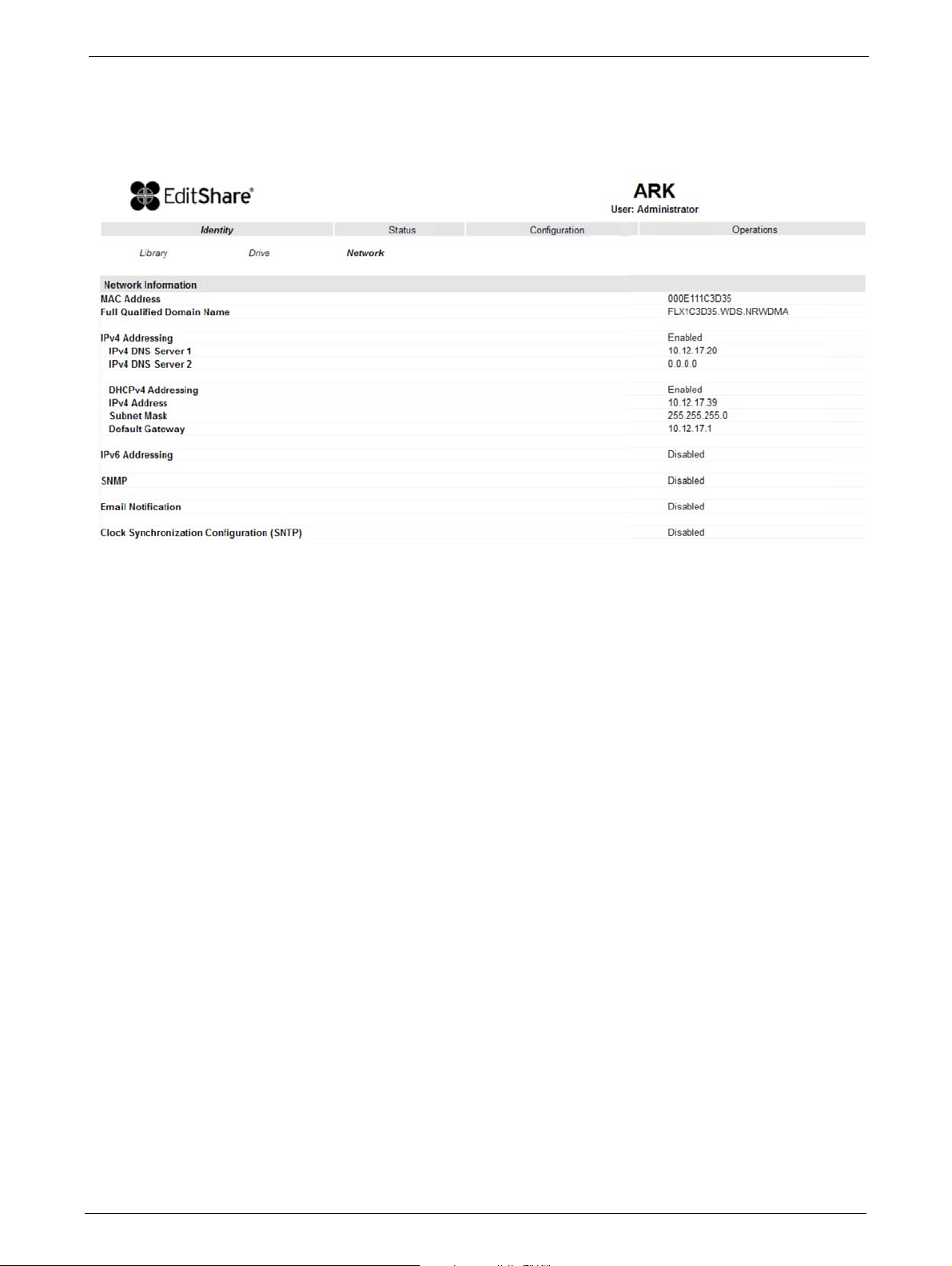
Viewing Network Identity
This page provides access to the network information about the connections of the library. No
changes can be made from this
page.
The following information is displayed:
1)
Network information:
• MAC Address
• Full Qualified Domain Name
• IPv4 Addressing = Enabled/Disabled
• IPv4 DNS Server 1 = IP address of domain name server 1
• Pv4 DNS Server 2 = IP address of domain name server 2
• DHCPv4 Addressing = En
• IPv4 Address = IP address assigned by DHCP
•
Subnet Mask
•Default Gateway = IP address of def
• Ipv6 Addressing = Enabled/Disabled
2) SNMP Information:
•SNMP = Enabled/Disabled
• Email Notification = Enabled/Disabled
• Clock Synchronization Configurat
ab
led/Disabled
on (SNTP) = Enabled/Disabled
i
ault gateway
48 TP-00347-01
Overview
Status
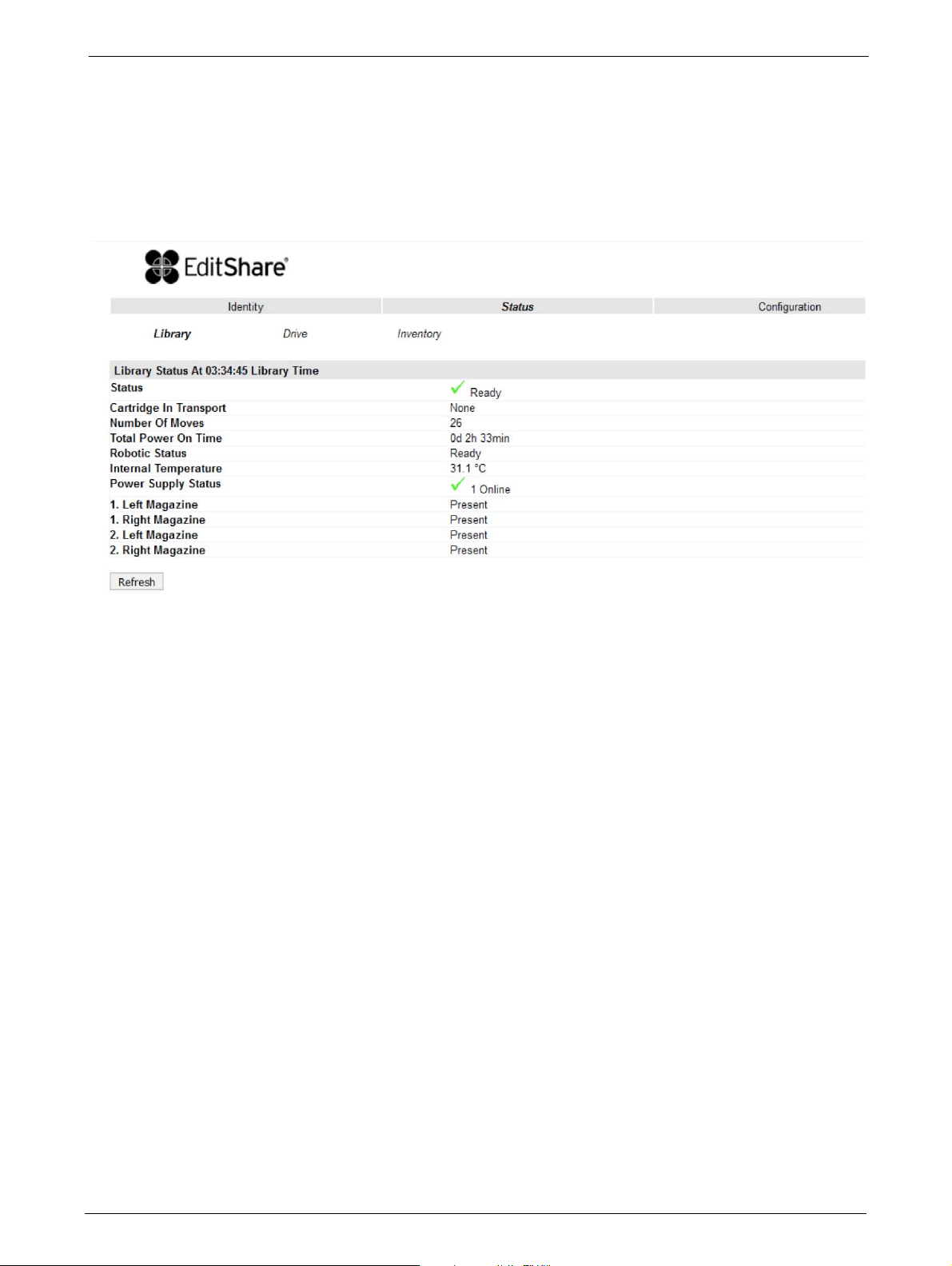
Viewing Dynamic Library Status
This page displays the dynamic information about the library, such as the current status of the
components.
The following information is displayed:
Status Indicates whether library is ready to accept commands
Cartridge in Transport Indicates whether the media changer contains a cartridge
Number Of Moves
(O
ometer)
d
Total Power On Time Indicates total library power-on time
Robotic Status Indicates whether the media changer is ready to accept commands
Internal Temperature Indicates internal unit temperature in degrees centigrade
Left/Right Magazine Indicates presence or absenc
Indicates total number of moves made by the media changer
e of tape magazines
TP-00347-01 49

Viewing Dynamic Drive Status
This page provides detailed information about all drives that are present in the library.
Chapter 4: Operation
If multiple tape drives are installed in the library, the info
the pull down menu.
rmation can be shown by selecting it from
The following information is displayed:
1) Drive Status
Status Indicates whether drive is ready for use
Cartridge in Drive Indicates whether the drive contains a tape cartridge
Drive Error Code
Drive Temperature
Cooling Fan Active
Drive Activity
Drive Port Information relevant to the specific drive interface (FC or SAS)
2) Additional drive information (up to 4
f-height tape drives for a 48Q)
hal
50 TP-00347-01
Overview
STEPS
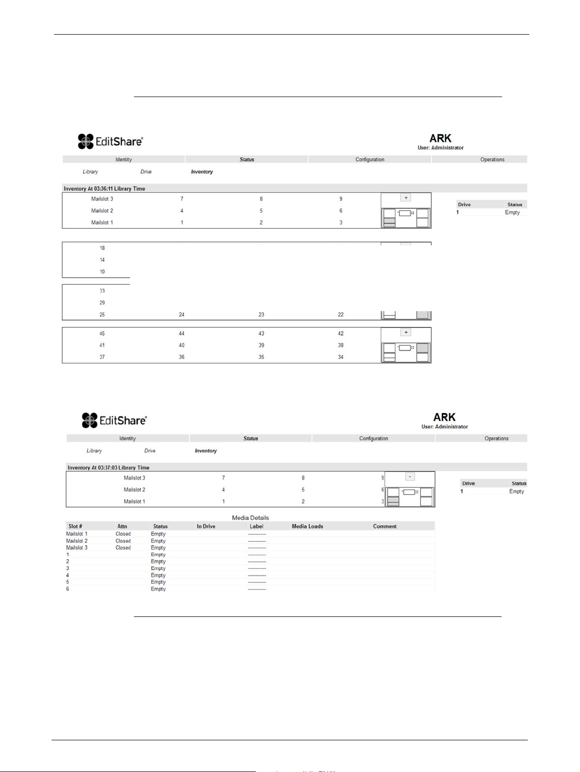
Viewing Tape Cartridge Inventory
This page provides detailed information about the tape inventory in the library.
1. A summary of each magazine displays.
2. To show detailed informat
3. The display expands for the specified
4. Detailed cartridge information displays below the summary panel.
ion, click on the + button.
magazine.
TP-00347-01 51
Configuration
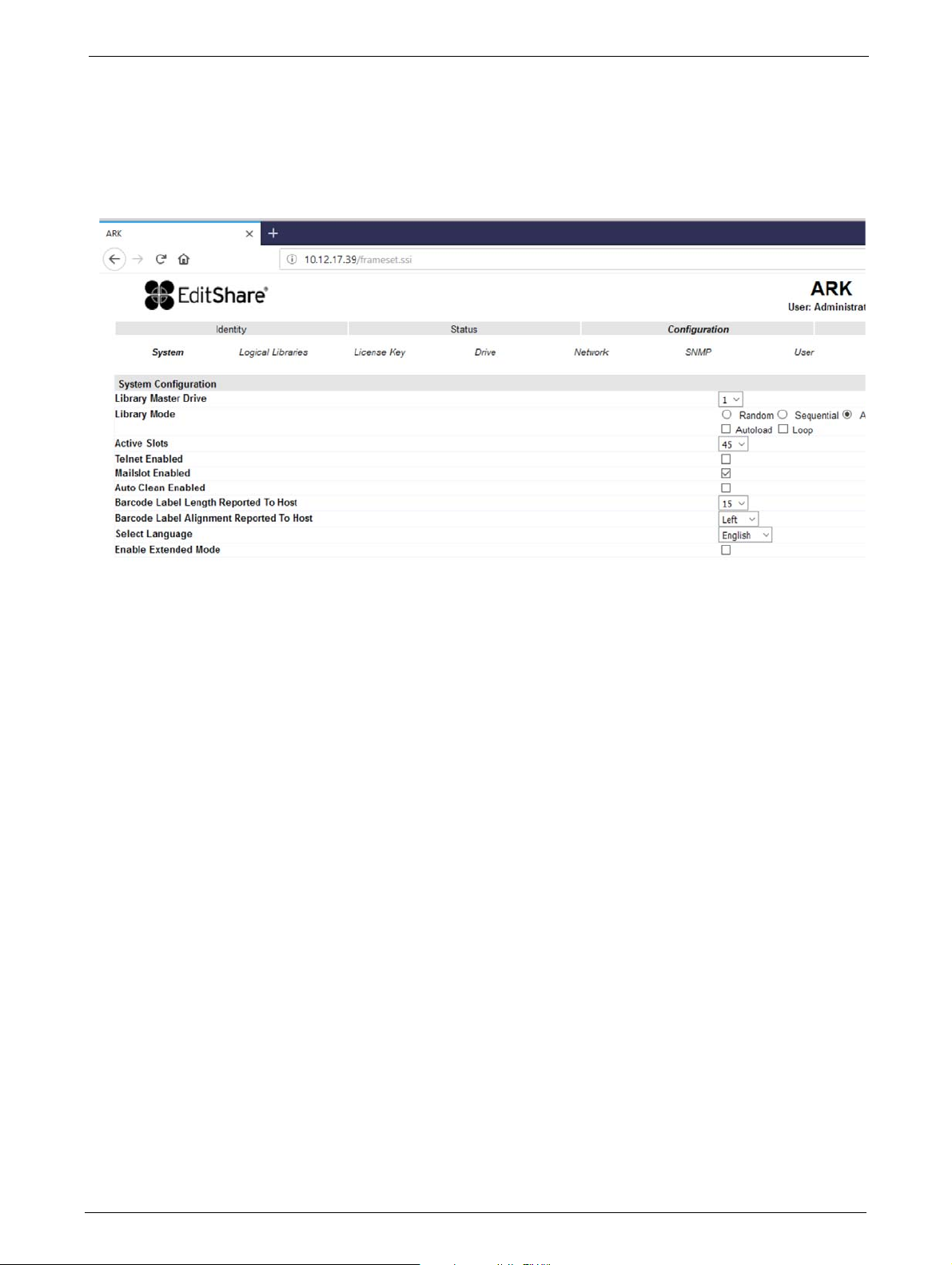
Changing the System Configuration
Chapter 4: Operation
This page allows the user to change the system configuration.
The following information displays:
1) Library Master Drive: - The drive number that will host the library's logical unit number (LUN)
2) Library Mode: - One of three
• <Random> In random mode, the library does not automatically load tapes into the tape
dr
ives. The random mode is used with a full featured or a media changer-aware backup
application and is the most common mode of operation.
• <Sequential > In sequential mode, th
from the tape drive. The sequential mode is used when the backup software is not
media changer-aware or was designed for standalone drives only.
• <Automatic> This is the defa
sequential mode into random mode when it receives library SCSI commands through
its unique LUN.
In sequential mode, the user can set the <Loo
load mode, the library automatically loads the tapes from the lowest-numbered full slot
into the tape drive. In loop mode, the original first tape in the sequence is reloaded after
the library has cycled through all available tapes.
3) Active Slots: - In this field the user can select the number of slots in the library that are available to the backup software.
4) Mailslot Enabled: - Enabling the mailslot in the library reduces the total number of available
storage slots to the library's max
behavior modes - Random, Sequential or Automatic
e library automatically loads and unloads tapes
ult mode. In automatic mode, the library switches from
p> and <Autoload> options. In the auto
imum slot count, less the number of mailbox slots.
5) Auto Clean Enabled: - When auto clean is enable
cartridge when a tape drive needs to be cleaned. The library identifies a tape as a cleaning
tape if it has a bar code label that starting with CLN or after an unlabeled cleaning tape has
been loaded into the tape drive.
52 TP-00347-01
d, the library automatically loads a cleaning

Overview
6) Select Language: - The select language menu allows the user to specify the language
displayed by the RMU interface. The default display language is English. Possible alternate
language selections are German, Italian, Spanish, and French. In order for the selection to
take affect the desired language must be selected in the drop down menu and the apply
button pushed. The web screen must then be refreshed.
Changes will only be applied after the <Refresh> or the <Apply> button is selected. After doing so,
rning page will inform the user of the impact of the proposed change. In some cases, a pop-up
a wa
screen will ask the operator to confirm the change. Many changes will also require a reboot.
Configuring Logical Libraries
The logical libraries drop down allows the user to partition one library into smaller "logical
libraries". Each logical library must contain at least one tape drive. For more information on this
feature, see "Partitioning the Library" on page 66.
Changing the License Key Configuration
This page allows the user to add additional functionality to the unit by entering license key
information. License keys are not required EditShare Ark
Tape Libraries.
TP-00347-01 53
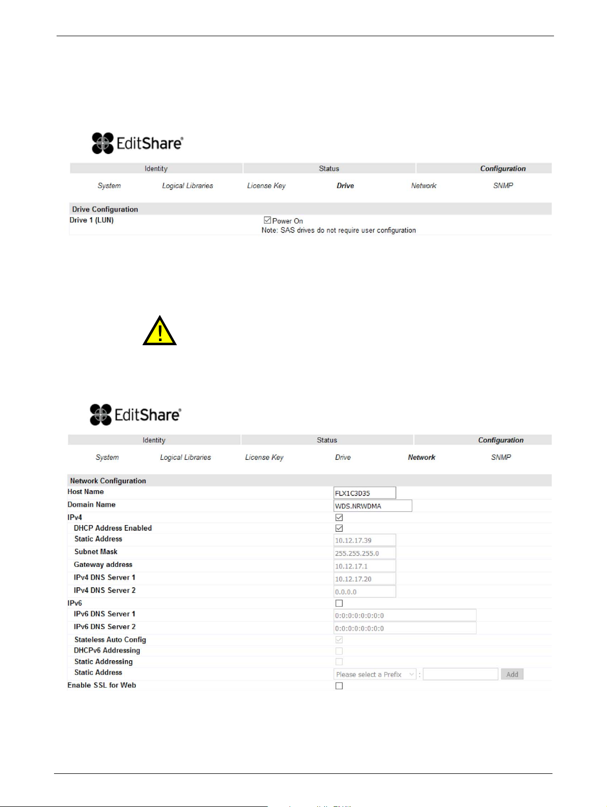
Chapter 4: Operation
Changing the Drive Configuration
This page shows the current configuration of all tape drives in the library and allows modification
to the configuration. The user is also able to select the <Power On> check box through this page
to activate the
drive.
Changing the Network Configuration
Changes in this menu may affect the ability to access the RMU interface unless
the correct IP Address is resolved.
This page shows the current network configuration of th
allows modification to the configuration. When a change is requested, a pop-up window will ask
you to confirm the
changes.
e library related to the RMU access and
54 TP-00347-01

Overview
Changes that can be made are:
• Host Name: In this box enter the name
you wish to use to address this library in the future. It
is recommended that you use a name that is relevant to its location and/or its purpose. The
Host Name may be up to 15 characters long.
Allowed characters are: [A-Z], [a-z], [0-9], hyphen [-] and period [.]
Disallowed characters are: hyphen [-] as the first character, blanks or consecutive hyphens
[-]
•
Domain Name: In this box is the domain in which th
e library is registered. It may be updated
by editing the name and submitting the changes. The Domain Name may be up to 39 chars
long.
Allowed characters are: [A-Z], [a-z], [0-9], hyphen [-] and period [.]
Disallowed characters are: hyphen [-] as the first character, blanks or consecutive hyphens
[-],
blanks or consecutive hyphens [-] as the first or last
character of a label (A period [.] is the delimiter of domain
name labels!)
The sum of characters of the Host Name and the Domain Name may not
exceed 54
(15+39) characters.
•IPv4:
• DHCP Address Enabled - Used to set the RMU to seek
an assigned IP address from the
network's DHCP server.
• Static Address - This field is only active with DHCP a
ddress off (unchecked), a static IP
address may be programmed in this field.
• Subnet Mask - Used to set the Network Mask, contact your Network administrat
receive this setting address if required.
• Gateway address - Used to set the Gateway Address; contact your Network administrator
to receive thi
s address if required (used when an IP address does not match any other
routes in the routing table)
• IPv4 DNS Server 1 - This is the IP address of your name server (DNS server). A DNS server
s the library to communicate with other network clients via their host name. If you
allow
have a DNS Server on your network, enter the IP address in this field.
• IPv4 DNS Server 2 - This is the alternate IP address of your name server (DNS server). A DNS
r allows the library to communicate with other network clients via their host name.
serve
If you have a DNS server on your network, enter the alternate IP address in this field.
•IPv6:
• IPv6 DNS Server 1 - This is the IP address of your name server (DNS server). A DNS server
allow
s the library to communicate with other network clients via their host name. If you
have a DNS Server on your network, enter the IP address in this field.
• IPv6 DNS Server - This is the alternate IP address of your name server (DNS server). A DNS
rver allows the library to communicate with other network clients via their host name.
se
If you have a DNS server on your network, enter the alternate IP address in this field.
• Stateless Auto Configuration
• DHCPv6 Addressing - Used to enable DHCP addressing assignment from the network
name
server
or to
• Static Addressing - Used to enable a static IP address for the
RMU access
• Static Address - Setting of the static IP address for the RMU
•
Enable SSL for Web
TP-00347-01 55

Chapter 4: Operation
Changing SNMP Settings
If a host and domain name is entered instead of an address, the IPv4 or IPv6 address will be
resolved from the DNS using that name. The IP address will be stored in the library rather than the
name. Therefore, if the address changes then the name or a new address will have to be
entered.
Changes that can be made are:
•SNMP Enabled/Disabled
• IPv4 SNMP Target Addresses
•IPv4 Target 1
•IPv4 Target 2
•IPv4 Target 3
• IPv6 SNMP Target Addresses
•IPv6 Target 1
•IPv6 Target 2
•IPv6 Target 3
• Community name
• Security User Name
• SNMP Trap Notification Filter
• Critical Events
• Critical and Warning Events
• Critical, Warning and Configuration Events
• Critical, Warning Configuration and Informa
t
ion Events
•No Events
56 TP-00347-01

Overview
Changing User Settings
This page allows the user to add and modify user accounts.
Changes that can be made are:
Access Level: Choose from 1 (Standard), 2 (Admin), or 3 (Service).
Access Level Name: The name associated with the chosen access level.
"New Password: The password can be a maximum of ten characters.
Repeat Password: Enter the new password again.
OCP Access PIN Enabled: Select this item, if you would like
e Operator Control Panel
th
display to be password protected.
OCP Access PIN Code: The password for accessing the OCP when the OCP Access PIN
is ena
bled; max 4 characters
Repeat OCP Access PIN Code: Enter the OCP Access PIN Code again.
Support Name: The name of the individual within your company to contact
f
RMU or library support; max 30 characters
or
Support Phone: The phone number of the individual within your company to
contact
for RMU or library support; max 30 characters
Support Email: The email address of the individual within your company to
contact
for RMU or library support; max 30 characters
TP-00347-01 57

Setting Date/Time
This page allows the user to set the time and date, and how it displays.
Changes that can be made are:
Chapter 4: Operation
Clock Configuration
• Time (24 hour format): hh:mm:ss
•Date: MM:DD:YYYY
• Clock Synchronization Configuration (SNTP):
• Enable Clock Synchronization: If checked the unit will attempt
with an external time source. The following apply:
• SNTP Server Address (IPv4): This is the IP address of the network
address may be a maximum of 40 characters.
• UTC T ime Zone Offset: Thi s drop down m enu allows the a dminist rator to sel ect the a ppropriate time zone offset so that the time wi
• Daylight Saving Enabled: Provides for automatic offset of daylight
ll be displayed in the actual local time.
to synchronize its clock
SNTP time server, the
savings time.
58 TP-00347-01

Overview
Setting Error Log Mode
Only Service personnel can set the log configuration.
The Log menu can be used to set behavior of the error log collection. Your service person may ask
you to alter sett
collection of logs, with the most recent events overwriting the oldest events (circular
Selections available are:
ings in this field during the diagnostic process. The default setting is for continuous
buffer).
•Error Log
•Trace Level
•Trace Filter
Configuring Event Parameters for Email Notification
This page allows the user to modify the event notification parameters.
Changes that can be made are:
Notification Level: Critical / Warning / Configuration events / none
To Email Address: max 40 characters
SMTP Server Address: IPv4 address or Host
TP-00347-01 59
name and domain

Chapter 4: Operation
Restoring Factory Defaults
This page allows the user to reset the configuration to the factory defaults, and save or restore vital
product
Selections available are:
Configuration Reset
data.
<Restore> factory
defaults:
Save/Restore Configuration
<Save> Configuration
F
ile:
to
<Restore>
nfiguration from File:
o
C
Selection of this button will restore all factory default settings
as outlined in Section 5.4. Please note that OEM library
applications may require operational settings which differ
from the factory default settings. Please consult your system
vendor to verify proper operational settings of the unit after a
restore to factory defaults.
The <Save> button will save the current library settings to a
file which can later be uploaded back to the library to restore
the settings. library configuration files have a ".dbb" file
extension with a file name format structure consisting of the
unique 10 character library unit serial number followed by a
,
followed by a date time stamp formatted
space
"YYMMDDTTTT" (YY= last two digits of current year, MM =
month number, DD = date, TTTT= Hour/minute time stamp
(24 hour time format)).
The <Browse> / <Restore> buttons enable the administrator
to select a path to a previously generated configuration file.
Once the correct file is located the <Restore> button is used to
upload the file back to the library.
60 TP-00347-01

Operations
Operations
Move Media within the Library
This page allows the user to move tape cartridges within the library.
Select the source and destination and then click
Determining Current Media Inventory
This page allows the user to rescan the library to determine the current media inventory.
Changes are only applied after the <Rescan> button is selected.
the <Move> button to move a tape cartridge.
TP-00347-01 61

Releasing and Replacing Magazines
To release a magazine manually, see "Emergency Release" on page 84. This manual
process should only be used if the magazine cannot be released using the OCP or the
This page allows the user to release the right or left magazine from the library.
Select the magazine in the pull down menu and then click the <Release> button.
Service
Chapter 4: Operation
RMU.
Performing General Library Diagnostics
This page provides the system administrator with general tests to verify the usability and reliability
library.
of the
Selections available are:
•System Test
• Slot To Slot Test
Select the number of test cycles (No. Cycles) before sta
completes, select the <Stop> button.
ting the test. To cancel the test before it
r
62 TP-00347-01

Operations
Performing Drive Diagnostics
This page provides the system administrator with general tests to verify the usability and reliability
drive(s).
of the
Selections available are:
Advance Diagnostic Select drive# and Select the Drive Test to be performed
Drive Support Ticket Select drive# and choose last/current unload
Save Drive Dump Select drive (once defined
Determining and Updating Firmware
This page displays the current versions of the library firmware and drive(s) firmware. New firmware
can be uploaded to the library or a drive by using this page. After a firmware update, the system
restarts auto
matically.
TP-00347-01 63

Chapter 4: Operation
Rebooting the Library
Ensure that the library is idle before attempting to perform any remote operations that will
take it offline.
Some RMU options take the library offline. This inactive mode can interfere with the
EditShare Ark T
This page is used to perform a library reboot. During a reboot, the RMU's connection to the library
may be lost, depending on the timing of the reboot. This is because the RMU web page refreshes
itself at intervals defined by a default time delay. If the reboot completes successfully during this
delay, the connection will remain intact. If not, the user will have to restart the RMU
ape application, causing data loss.
login.
Viewing Library Logs
This page allows the user to view the library logs.
The user can specify the following information:
•Log Type:
•Error Trace
• Informational Trace
•Warning Trace
• Configuration Change Trace
•Standard Trace
• Start Entry
• Number Of Entries Per Page
Changes are only applied after the <Update> or <Clear Log> button is selected.
<Dump log> creates the log and <Save Service Dump> allows the direct viewing or saving of the
file.
64 TP-00347-01

Operations
Cleaning Tape Drive(s)
This page allows the user to initiate the tape drive cleaning process, if required.
Select the magazine slot number containing the cleaning cartridge and the tape drive to be
clea
ned in the appropriate pull down menu and then click the <Clean> button.
Cartridge Memory
Provides details of the tapes stored in the library.
TP-00347-01 65

Partitioning the Library
Editshare Ark Tape is designed to support a tape library with only one partition.
Partitioning information is for reference only.
The Ark Tape Libraries may be addressed either as a single 'Logical library', or it may be partitioned
into logical libraries. In the case of the 24Q, two half-height tape drives must be installed and the
library may be set to a maximum of two partitions, because each drive is fully dedicated to a single
partition. Similarly, each 12-slot magazine is fully dedicated to a single partition. (Note however,
that a single partition may include multiple magazines and multiple drives.) The 48Q may be
partitioned up to a maximum of four partitions (each requiring a dedicated tape drive).
The SCSI element addresses shown below are default values which are valid in a new
library or after a "Reset to Default". They can be changed by SCSI SMC command.
24Q Tape Library
Chapter 4: Operation
24Q Single Partition Configuration
Tape Drive 1 half-height drive (default element addresses = 256 )
Tape Drive 2 half-height drive (default element addresses = 257 )
Magazines #1 and #2
24Q Dual Partition Configuration
The mailslot (if configured as MAIL) is shared between the logical libraries.
Partition 1
Tape drive 1: half-height drive (default element address = 256)
Magazines: #1
Partition 2
Tape drive 2: half-height drive (default element address = 256)
Magazines: #2
66 TP-00347-01

Partitioning the Library
48Q Tape Library
48Q Single Partition Configuration
Tape drive 1: half-height drive (default element addresses = 256 )
Tape drive 2: half-height drive (default element addresses = 257 )
Tape drive 3: half-height drive (default element addresses = 258 )
Tape drive 4: half-height drive (default element addresses = 259 )
Magazines: #1 through #4
48Q Dual Partition Configuration
The mailslot (if configured as MAIL) is shared between the logical libraries.
Partition 1
Tape drive 1: half-height drive (default element address = 256)
Tape drive 2: half-height drive (default element address = 257)
Magazines: #1 and #2
Partition 2
Tape drive 3: half-height drive (default element address = 256)
Tape drive 4: half-height drive (default element address = 257)
Magazines: #3 and #4
48Q Three Partition Configuration
The mailslot (if configured as MAIL) is shared between the logical libraries.
Partition 1
Tape drive 1: half-height drive (default element address = 256)
Magazines: #1
Partition 2
Tape drive 2: half-height drive (default element address = 256)
Magazines: #2
Partition 3
Tape drive 3: half-height drive (default element address = 256)
Tape drive 4: half-height drive (default element address = 257)
Magazines: #3 and #4
TP-00347-01 67

48Q Four Partition Configuration
The mailslot (if configured as MAIL) is shared between the logical libraries.
Partition 1
Tape drive 1: half-height drive (default element address = 256)
Magazines: #1
Partition 2
Tape drive 2: half-height drive (default element address = 256)
Magazines: #2
Partition 3
Tape drive 3: half-height drive (default element address = 256)
Magazines: #3
Partition 4
Tape drive 4: half-height drive (default element address = 256)
Magazines: #4
Chapter 4: Operation
Removed Drives
If a drive is physically removed, it is reported to the host application by reference to its SCSI
element address. It is reported as 'not accessible' until it is inserted again in the drive slot and
either:
• A "Reset to Default" from any u
• The logical library configuration chan
ser-interface occurs, or:
ges (adding/removing of libraries)
68 TP-00347-01

Default Settings
Default Settings
Setting Library Default
Initial admin password adm001
Host name FLX + last 6 characters of MAC address
Domain name localdomain.com
IPv4 Enabled
IPv6 Disabled
DHCP Disabled
Mailslot configuration Disabled
Configure reserved slots Reserved slots = 0
SCSI master drive The lowest physical drive is initially the LUN master drive.
OCP contrast setting 10
Library Mode Automatic
Auto load Disabled
e.g. MAC = 000E11801907, host name = FLX801907
Loop Disabled
Drive power <ON/OFF> All drives are powered <ON>
Auto clean Disabled
SNMP Disabled
FC Tape Drives Automatic speed, auto topology
Log Tracing Configuration All selected
Email notification No events
Partitioning Partitioning is turned <OFF>
TP-00347-01 69

Chapter 4: Operation
70 TP-00347-01

Chapter 5: Servicing
Static Sensitive Devices are used in this Equipment.
This chapter describes the procedures for servicing the tape librar
• "Tools Required" on page 71
• "Storing and Shipping Components" on page 71
• "Tape Drives" on page 72
• "Library Controller" on page 73
• "Power Supplies" on page 74
• "Servicing a Magazine" on page 75
• "Base Chassis" on page 75
• "Packaging the Unit for Transportation" on page 76
Tools Required
The following tools are required to service the tape library:
Always observe the procedures for handli
"Warnings and Cautions" on page 3.
ng these devices as described in
ies. See the following sections:
•No. 2 and No. 3 Phillips Screwdrivers
• Flat Blade Screwdrivers - Large and Small
•Ground Strap
Storing and Shipping Components
When storing or shipping components such as tape drives, library controllers and power supplies,
always repackage them in the original or replacement device packaging materials.
TP-00347-01 71
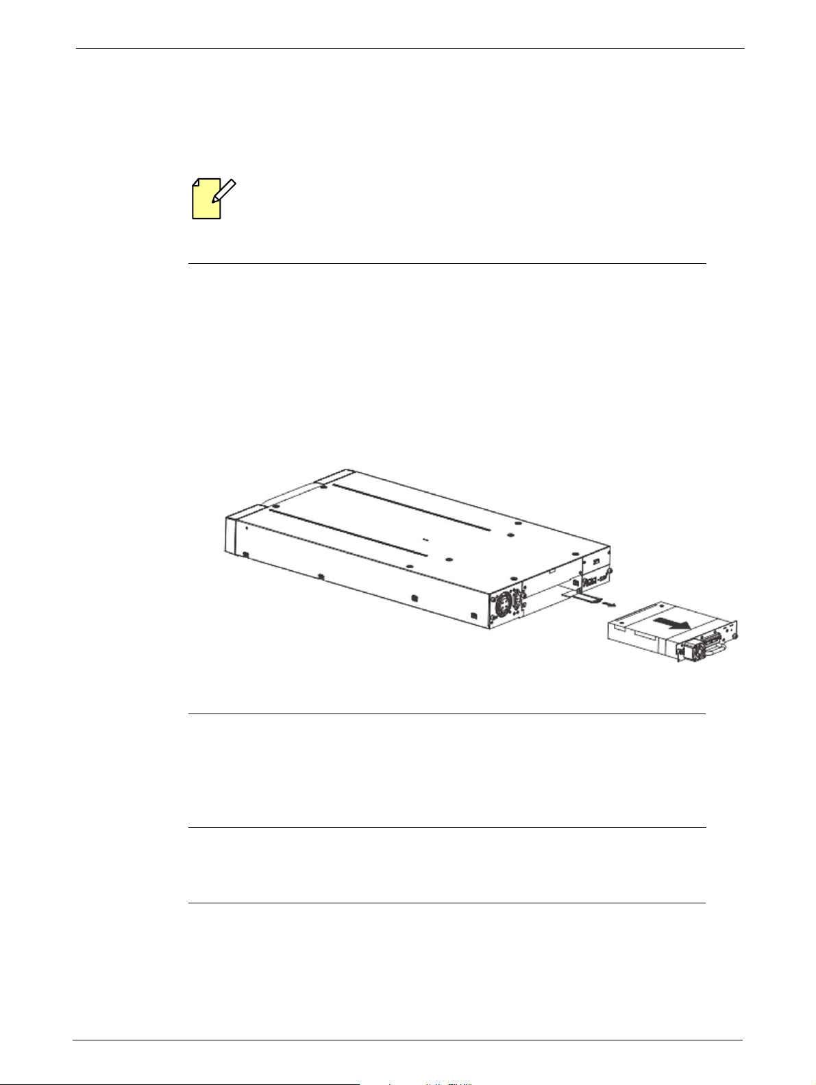
Tape Drives
STEPS
STEPS
Removing a Tape Drive
Tape drives are hot pluggable. It is not mandatory to power down the library to replace a
drive.
To remove a tape drive:
1. Unload the tape cartridge from the tape drive (if present) using:
• "Operator Control Panel (OCP)" on page 33
• "Remote Management Unit (RMU)" on page 44
Chapter 5: Servicing
2. Remove all affected tape drive ca
3. Loosen the blue thumbscrews located on the rear of the t
4. Slightly pull out and push down the tab containing the product ID label so it does not
interf
ere with the tape drive as shown
5. Pull the tape drive by the handle straight out of the library.
Replacing a Tape Drive
bles on the rear panel.
ape drive with your fingers.
below.
To replace the tape drive with another tape drive:
1. Remove the tape drive from the library, as described in "Removing a Tape Drive" on page 72.
2. To install the new tape drive, see "Installing Tape Drives" on page 23.
72 TP-00347-01
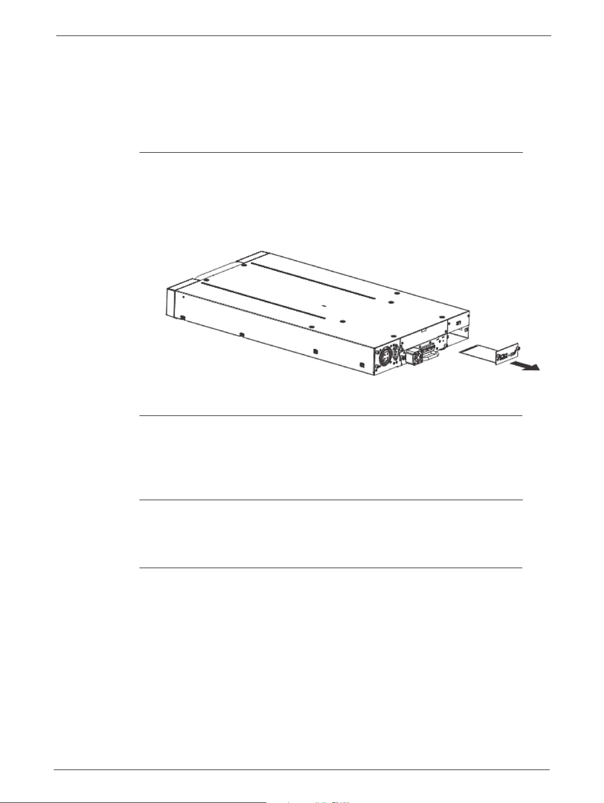
Library Controller
STEPS
STEPS
Library Controller
Removing a Library Controller
To remove the library controller:
1. Power down the library by pressing the power button on the front panel.
2. Remove the power cord from the rear panel of the library.
3. Remove all cables from the library controller on the rear panel of the library.
4. Loosen the blue thumbscrews lo
5. Pull the library controller straight out of the library as shown in the diagram.
Replacing a Library Controller
To replace the library controller with unit:
1. Remove the library controller from the library, as described in "Removing a Library
Controller" on page 73.
cated on the library controller with your fingers.
2. To install the new library controller, see "Installing the Library Controller" on page 24.
TP-00347-01 73

Power Supplies
STEPS
STEPS
Removing a Power Supply
To remove a power supply:
1. Power down the library by pressing the power button on the front panel.
2. Remove the power cord on the rear panel of the library.
Chapter 5: Servicing
3. Loosen the blue thumbscrews located on the rear
4. Pull the power supply straight out of the library as shown in the diagram.
Replacing a Power Supply
To replace a power supply:
of the power supply with your fingers.
1. Remove the power supply from the library, as described in "Removing a Power Supply" on
page 74.
2. To install the new power supply, see "Power Supply Installation" on page 25
74 TP-00347-01

Servicing a Magazine
STEPS
STEPS
Servicing a Magazine
To remove a magazine:
1. Unlock the appropriate magazine, using:
• "Operator Control Panel (OCP)" on page 33
• "Remote Management Unit (RMU)" on page 44
• "Emergency Release" on page 84 - Use this method if you are unable
magazine with the OCP or RMU
2. Pull the released magazine out of the library.
3. Remove all tape cartridges from the magazine.
4. To store or ship the removed magazine, repackage it
materials.
5. Insert an appropriate magazine into the empty magazine slot of
6. Slide the magazine completely into the library. The magazine locks into place once it is
correctly installed.
Base Chassis
Preparing to Remove the Base Chassis
The Base Chassis is heavy, observe the Safety Procedures described in page 3.
to unlock the
in the replacement device packaging
the library.
1. If the OCP or RMU is working:
• Write down the system, drive, and network configuration settings. You will need these
settings to re-configure the library after replacing the base chassis.
• Remove all tape cartridges to reduce the weight, see "Removing Tape Cartridges from
Tape Library" on page 83
• Remove the magazines from the libr
2. If the OCP or RMU does not work, remove the magazines manually. See "Emergency Release"
on page 84.
3. Power down the library by pressing the
4. Remove the cables from the rear panel of the library.
5. Remove the power supply - see "Removing a Power Supply" on page 74
6. Remove the tape drive(s) - see "Removing a Tape Drive" on page 72.
7. Remove the library controller - see "Removing a Library Controller" on page 73.
TP-00347-01 75
ary, using the OCP or RMU.
power button on the front panel.

Removing the Base Chassis from the Rack
STEPS
STEPS
To remove the Base Chassis from the Rack:
1. Using a 3# Phillips screwdriver placed through the small holes in the mounting bracket to
loosen the M5 screw(s) on each side of the library.
2. Remove the library from the rack rails, and then remove the mounting brackets of the
library.
3. If available:
• Remove the shipping lock and the yellow label from the rear panel.
Chapter 5: Servicing
• Insert the shipping lock into
• Stick the yellow label over the shipping lock to secure it in place.
the slot on top of the library.
Packaging the Unit for Transportation
The Base Chassis is heavy, observe the Safety Procedures described in page 3.
Before packaging the library:
1. Pull out the tab with the product ID label (1)
2. Note the part and serial number (2)
3. Package the library as shown in page 77 (24Q Ark Tape Library) or page 78 (48Q Ark Tape
Library).
4. If returning the unit to Editshare for repair, please call the Technical Support department to
request an RMA number.
76 TP-00347-01

Packaging the Unit for Transportation
24Q Ark Tape Library
1 Packaging Box
2 Bottom Shell
3 Library
5 Top Shell
TP-00347-01 77

48Q Ark Tape Library
Chapter 5: Servicing
1 Packaging Box
2 Bottom Shell
3 Library
4 Middle Shell (Q48 only)
5 Top Shell
78 TP-00347-01

Chapter 6: Troubleshooting
This section provides information for verifying correct installation of your Q24/Q48 tape library and
troubleshooting any issues that might arise with it.
• "Installation Issues" on page 79
• "Troubleshooting Checks" on page 80
• "Removing Tape Cartridges from Ta
• "Emergency Release" on page 84
• "Upgrading the Library Firmware" on page 85
• "Service Diagnostics" on page 86
• "Error Codes" on page 87
Installation Issues
Issues encountered during the installation of the library are usually caused by cabling, application
software configuration errors, or an incorrectly configured operating system. If the host
application software is not communicating with the library after installation, check the following:
Cabling
Check that all cables to the tape library, including power, SAS and/or Fibre Channel, as well as
Ethernet and USB (if present) are properly seated in their respective sockets at both ends, and that
the tape library is powered on. If so, and the host is still not communicating successfully with the
library, then the cables themselves may need to be checked. If spare cables are available, this can
be achieved by replacing one cable at a time and assessing whether the problem is cured as a
result.
pe Library" on page 83
Power may be left on while exchanging any of the data cables, as their removal and replacement
will not
cause damage to the library.
Compatibility
Ensure that the library is compatible with the backup application you plan to use. For a list of
compatible application software, check with your backup application vendor.
Backup Application Installation
Refer to the documentation included with your backup application for instructions on how to
verify proper installation. Some backup software packages require an additional module to
communicate with the library media changer.
TP-00347-01 79

Device Driver Installation
Many backup applications use their own drivers for the library and tape drive. Before
installing a driver, make sure it will not be in conflict with the soft
Make sure that the proper device driver, if applicable, is installed for the library. Contact your
support representative for more information.
Troubleshooting Checks
Performance
ISSUE SOLUTION
Chapter 6: Troubleshooting
ware.
Poor Throughput
Pe
rformance
Cleaning Cartridge
Try a new tape. A marginal tape can cause performance
problems due to bad spots on the tape requiring retries.
Backing up data that compresses poorly or is
compressed will lower performance.
Check the size of the files. Small file size can impact
perf
ormance.
Confirm that the backup application is utilizing block siz
at least 32KB, preferably 64KB. Refer to the backup application
documentation for details.
Check the network bandwidth from the host computer. If you
are back
local-only backup.
Make sure the backup server has enough memory to handle
the ba
Clean the tape drive using:
• OCP, see "Service Menu" on page 42
•RMU, see "Cleaning Tape Drive(s)" on page 65
ing up data over a network, consider comparing to a
ndwidth of the backup or restore.
already
es of
ISSUE SOLUTION
Cannot load the cleaning
car
tridge
80 TP-00347-01
Make sure you are using an Ultrium universal cleaning
cartridge.
Contact your service representative.

Troubleshooting Checks
Errors Displayed on Operator Control Panel (OCP)
ISSUE SOLUTION
Media
"!" in library operator panel
inventor
There is an error code on the
LCD
ISSUE SOLUTION
Cleaning or data tape
inco
Cannot write to or read from
tape.
y display
mpatible with drive.
Export the tape cartridge marked with an "!" in the inventory.
The tape cartridge is either damaged, incompatible with the
tape drive, or the wrong type for the attempted operation.
To find the compatible tape cartridges for your library, see
"Use and Care of Tape Cartridges" on page 29
Look up the error code, try to resolve the failure, and cycle the
power. See "Error Codes" on page 87.
Make sure you are using data and cleaning tapes that are
compatible with the drive and model of your library.
The library automatically unloads incompatible tapes, the
<Me
dia Attention> LED flashes, and an exclamation mark (!) is
displayed in the inventory display for the indicated slot
number.
Export the media in order to clear the state.
Ma
ke sure that the tape is write enabled (move the
write-protect switch to the enabled position).
Make sure you have the appropriate data tape for your library
model.
M
ake sure you are using an Ultrium tape that has not been
degaussed.
Make sure that the tape has not been exposed to harsh
envir
onmental or electrical conditions and is not physically
damaged in any way.
Many backup applications do not read or write to tapes that
we
re created using a different backup application. In this case,
perform an erase, format, or label operation on the tape.
Make sure you understand any data protection or overwrite
prot
ection schemes that your backup application may be
using, which could prevent you from writing to a given tape.
Retry the operation with a different, known good tape.
Clean the tape drive using:
- OCP, see "Service Menu" on page 42
- RMU, see "Cleaning Tape Drive(s)" on page 65
Do not degauss Ultrium tapes.
TP-00347-01 81

Power
ISSUE SOLUTION
Library does not power up. Check all power cord connections.
Make sure the power switch on the front panel is in the <ON>
position.
ke sure there is power to the outlet. Try another working
Ma
outlet.
e the power cord.
Replac
Contact your service representative.
No display messages appear. Make sure the power cord is connected.
Make sure the power switch is on.
Power cycle the library.
Download the library firmware.
Chapter 6: Troubleshooting
<Media Attention> LED issues
ISSUE SOLUTION
Contamination by loose
debris:
Non-acclimated media: A tape should be acclimated for at
Tape car tridge is
inco
mpatible:
Expired cleaning cartridge: Make sure you are using an Ultrium universal cleaning tape.
Bad/defective/contaminated
media:
Contact your service representative.
Avoid contamination by ensuring that the library is installed in
a clean
, contamination-free environment. Tapes should be
stored vertically in their plastic cases. Clean the tape drive(s) as
needed.
least 24 hours before being
used, particularly if it has been stored at a substantially
different temperature or level of humidity than the library.
Use only tapes that are compatible with the tape drive type.
See Section 4.14
(m
x. 50 cleans)
a
If the <Media Attention> LED is cleare
clean, but the LED immediately re-displays each time a
particular tape is loaded, that tape should be suspected of
being defective.
Export the tape and load a known good tape. In some cases, a
tape can b
been formatted as a Firmware Upgrade cartridge.
Any tape that is suspected of being defe
should NOT be reused in any drive.
e worn out, have a defective tape memory, or have
d and the tape drive is
ctive or contaminated
82 TP-00347-01
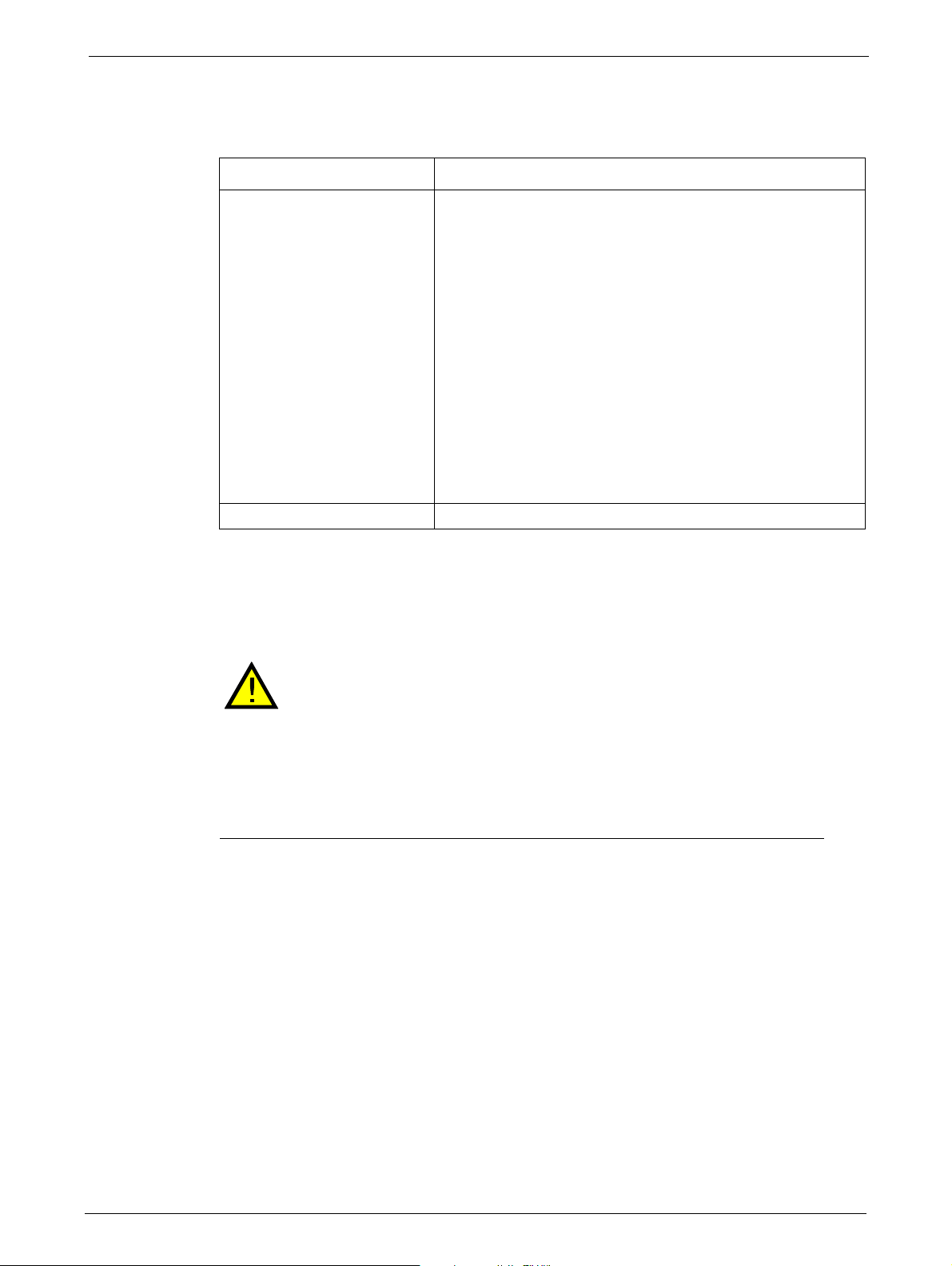
Removing Tape Cartridges from Tape Library
STEPS
Tape Cartridge Movement
ISSUE SOLUTION
Tape cartridge stuck in tape
drive
.
Tape stuck in storage slot. See Section 6.3.
Power cycle the library, allow it to complete initialization,
which in rare cases can take as long as 10 minutes, and then
retry unloading the tape using the library operator control
panel.
Allow the tape drive to complete all opera
as long as ten minutes if you reset or cycle power to the library
while the cartridge is positioned at the physical end of the
media.
Make sure that the backup software i
preventing the tape drive from ejecting the tape. The backup
software needs to cancel the reservation and any hold it has
on the tape drive. Temporarily disconnecting the library from
the host server and power cycling eliminates the host and its
software as a problem source.
Contact your Service Representative.
Removing Tape Cartridges from Tape Library
Risk of Damage to Devices when tape cartridges are stuck in the tape library
tions. This may take
s not reserving the slot or
When the library is moved, any tape cartridg
magazines and can damage other tape cartridges left in the library and the
library media handler.
To avoid damage, remove all tape cartridges before moving the library.
To remove
1. Unlock the magazine using the:
2. Pull the mailslot or magazine out
a stuck tape cartridge:
•OCP, see "Service Menu" on page 42
•RMU, see "Cleaning Tape Drive(s)" on page 65
• Emergency release, if you are not able to unlock the magazine with the OCP or RMU, see
"Emergency Release" on page 84.
access the tape cartridge.
to
e can become dislodged from the
TP-00347-01 83
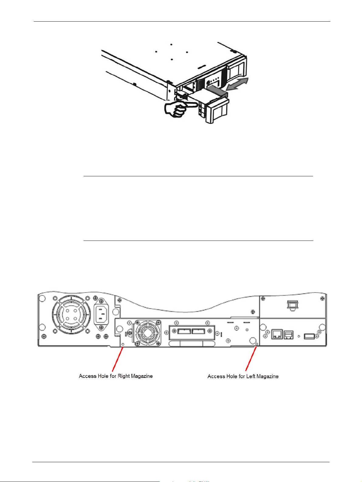
3. To remove the tape cartridge:
STEPS
• Use the finger holes to push the tape out of the slot.
• If required insert a new tape cartridge.
Chapter 6: Troubleshooting
• Repeat this process until all stuck tape c
4. Push the mailslot or magazine back into the library.
Emergency Release
If you cannot remove the magazines via the OCP or RMU, do the following:
1. Press the power button on the front bezel to power down the library.
2. Unplug the power cord from the library.
3. From the rear panel of the library, find the access holes for the right and left
artridges are removed.
magazines.
84 TP-00347-01
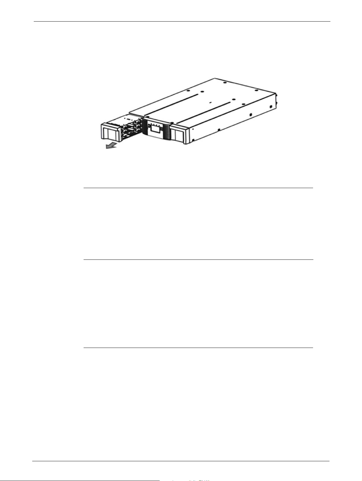
Upgrading the Library Firmware
STEPS
4. Push the end of a small metal pin or straightened paper clip into the magazine access hole
at the back of the device. While holding the pin or clip, have a second person attempt to pull
the magazine out of the front of the unit.
For the 48Q Tape Library, all magazines on a side are released and should be removed at the
same
5. If necessary, repeat the steps 3 and 4 for the other magazine.
time.
6. If you are unable to remove any tape cartridges or to release the
foregoing methods, contact your Service Representative.
Upgrading the Library Firmware
It is advisable to keep the library firmware updated to the latest version. To update the library
firmware:
1. Use the RMU or OCP to navigate to the appropriate screen:
• RMU screen: > Service > Firmware > Upgrade Library Firmware > Upload
• OCP screen: > Main Menu > Service > Se
2. Load the library firmware on to a USB stick, then insert the USB
panel of the library.
3. When the firmware file name displays, select it to start
4. After updating the library firmware, the library system restarts automatically
magazines by any of the
rvice Library > Library FW Upgrade by USB
stick into the port on the rear
the updating process.
TP-00347-01 85

Service Diagnostics
STEPS
STEPS
STEPS
System Test
The System Test is a general test to verify the usability and reliability of the library. Its duration
depends on the test cycles defined.
1. Use the RMU or OCP to navigate to the appropriate screen:
• RMU screen: > Service > General Diagnostic > System Test
• OCP screen: > Main Menu > Service > Service Library > Run Tests > System Test
Slot-to-Slot Test
The Slot-to-Slot test shuffles the tapes between the slots to exercise the media changer. At the end
of the test the tapes are not returned to their original slots.
Chapter 6: Troubleshooting
1. To run the Slot-to-Slot test, navigate with the RMU or OCP to the appropriate screen:
Library Verify Test
The library verify test is a diagnostic routine called Library Health Check (LHC). It includes:
• Functional testing of all library and drive hardware with the exception of external interfaces.
•
Verification of a newly inst
• Verification of repair actions.
The test requires user interaction and can only be run from the OCP. The administrator password
is required. To run the
1. Using the OCP, navigate to the test screen: Main Menu > Service > Service Library > Library
• RMU screen: > Service > General Diagnostic > Slot to Slot
• OCP screen: > Main Menu > Service > Service Library > Run Tests > Slot to Slot Test
When running this test, the library removes any tape from the tape drive(s) and goes offline.
Verify that any applications using the library h
alled machine.
LHC:
Verify.
ave completed before starting the test.
2. The library performs a self-test, verifying that it can communicate with the tape drives.
3. The library returns any tapes from the
tape is unknown, the library moves the tape to the mailslot and prompt the user to remove
it.
86 TP-00347-01
tape drives to their home slot(s). If the home slot for a

Error Codes
4. The library then prompts the user to enter the number of cycles to run the test. The
maximum is 10 cycles.
5. The library opens the mailslot and prompts
6. The user inserts a scratch tape into
the mailslot without inserting a tape into it, the library performs a shortened version of the
test, skipping step 7.
7. The library loads the scratch tape into the
the mailslot. If the user selected to test both the tape drives (if present), the library loads the
scratch tape into each tape drive before returning it to the mailslot.
8. The next test expects to find a tape in each of
The library moves each tape to the tape drive load point and then returns it to its slot. If none
of the top-row corner slot positions contains a tape, the test stops and the library displays
an error message.
9. If additio nal cycles r emain to be run, the test returns
or step 8 there is not.
10. At the conclusion of the test, th
the scratch tape.
11. The library displays the test completion status, including any recoveries or errors that may
have occurred.
the mailslot. If the mailslot is disabled or the user closes
e library opens the mailslot and waits for the user to remove
the user to insert a scratch tape.
first tape drive, then unloads it and returns it to
the top row corner slots of the two magazines.
to step 7 if there is a tape in the mailslot
Error Codes
Error Messaging
The internal error messaging between the different modules and tasks contain the following
information:
•Error code
• Sub error code
• Affected source element
• Affected target element
• Additional information depending
Error Message Format
The error message format is a fixed 4-byte length with the following content:
•Error type
•Error code
on context and error code
• Sub error code
• Internal code (active command code)
TP-00347-01 87
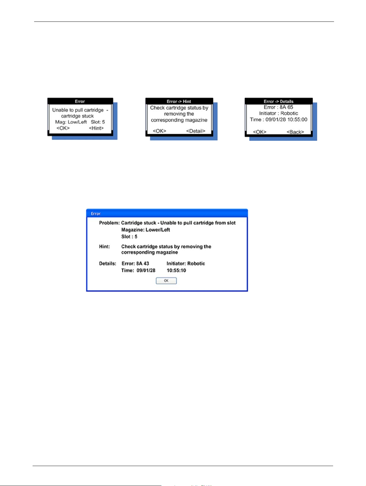
OCP Error Reporting
In case of an error or a warning, a popup message appears on the OCP. The information is shown
in three different message displays, as shown in the following example:
Chapter 6: Troubleshooting
General <Error> Display
Select the <Hint> button to show
in
the <H
t> display
RMU Error Reporting
In case of an error or a warning, , the following popup message appears on the RMU. All
information will be available in one message box, as shown in the following example:
<Hint> Display
Select the <Detail> button to show
etail> display
the <D
Detail Display
88 TP-00347-01

Error Codes
Main Error Codes
Error
Code Description User Action Critical Component Status
80 Barcode Reader Error, cannot
initialize B
81 Barcode Reader Error, no
r
esponse from BCR
82 EEPROM Error, no response from
EEPROM (loca
changer controller)
83 Media changer controller generic
pr
oblem
84 Setting of gripper motor
paramet
85 Setting of slider motor
paramet
86 Setting of elevator motor
paramet
87 Setting of rotation motor
paramet
CR
ted on media
ers failed
ers failed
ers failed
ers failed
Retry operation; after several
occurrences contact technical
support
Retry operation; after several
occurrences contact technical
support
Retry operation; after several
occurrences contact technical
support
Reset the unit and retry
operation. After several
occurrences contact technical
support
Reset the unit and retry
operation. After several
occurrences contact technical
support
Reset the unit and retry
operation. After several
occurrences contact technical
support
Reset the unit and retry
operation. After several
occurrences contact technical
support
Reset the unit and retry
operation. After several
occurrences contact technical
support
Media changer probably
defective.
Flexi cable to BCR not properly
con
nected.
Flexi cable to BCR damaged.
Barcode engine defect.
Media changer probably
defective.
Flexi cable to BCR not properly
con
nected.
Flexi cable to BCR damaged.
Barcode engine defect.
Media changer probably
defective.
Media changer controller not
w
orking (hardware problem,
EEPROM defect).
Media changer probably
ective.
def
Media changer hardware not
wo
rking (cables, distribution
boards, media changer
controller).
Media changer probably
ective.
def
Elevator distribution board
def
ect.
Cabling incorrect.
Media changer probably
ective.
def
Elevator distribution board
def
ect.
Cabling incorrect.
Media changer probably
ective.
def
Elevator distribution board
def
ect.
Cabling incorrect.
Media changer probably
ective.
def
Media changer controller defect.
TP-00347-01 89

Chapter 6: Troubleshooting
Error
C
ode Description User Action Critical Component Status
88 Setting of sled motor parameters
failed
Reset the unit and retry
operation. After several
occurrences contact technical
support
89 Gripper blocked Run 'Library Verify Test', after
eral occurrences contact
sev
technical support
8A Slider blocked Run 'Library Verify Test', after
sev
eral occurrences contact
technical support
8B Elevator blocked Run 'Library Verify Test', after
sev
eral occurrences contact
technical support
8C Rotation blocked Run 'Library Verify Test', after
sev
eral occurrences contact
technical support
Media changer probably
ective.
def
Media changer controller defect.
Media changer probably
defective.
Gripper motor not connected or
def
ect.
Gripper motor voltage too low.
Media changer controller or
distr
ibution boards defect.
Check gripper mechanism
ac
cording stiffness in movement.
Media changer probably
defective.
Slider Motor not connected or
def
ect.
Slider motor voltage too low.
Media changer controller or
distr
ibution boards defect.
Check slider mechanism
ac
cording stiffness in movement.
Media changer probably
defective.
Elevator motor not connected or
def
ect.
Elevator motor voltage too low.
Media changer controller or
distr
ibution boards defect.
Check elevator mechanism
ac
cording stiffness in movement
Media changer probably
defective.
Rotation motor not connected or
def
ect.
Rotation motor voltage too low.
Rotation home sensor defect.
Rotation sensor connecting
cable damaged
.
Media changer controller or
distr
ibution boards defect.
90 TP-00347-01

Error Codes
Error
C
ode Description User Action Critical Component Status
8D Sled blocked Run 'Library Verify Test', after
several occurrences contact
technical support
8E Cannot find gripper block within
th
e expected range
Run 'Library Verify Test', after
several occurrences contact
technical support
8F Cannot find slider block within
th
e expected range
Run 'Library Verify Test', after
several occurrences contact
technical support
90 Cannot find elevator block within
th
e expected range
Run 'Library Verify Test', after
several occurrences contact
technical support
91 Cannot find rotation block within
th
e expected range
Run 'Library Verify Test', after
several occurrences contact
technical support
92 Cannot find sled block within the
expe
cted range
Run 'Library Verify Test', after
several occurrences contact
technical support
93 Gripper outside range,
Gripper has reached a position
ond the expected range
bey
Run 'Library Verify Test', after
sev
eral occurrences contact
technical support
Media changer probably
defective.
Sled motor not connected or
def
ect.
Sled motor voltage too low.
Sled home sensor defect.
Sled sensor connecting cable
damaged
.
Media changer controller or
distr
ibution boards defect.
Check sled mechanism (guide
rail
, ducktail) according stiffness
in movement.
Media changer probably
defective.
Elevator distribution board
def
ect.
Cabling incorrect.
Check gripper gears.
Media changer probably
defective.
Elevator distribution board
def
ect.
Cabling incorrect.
Check slider gears.
Media changer probably
defective.
Elevator distribution board
def
ect.
Cabling incorrect.
Check elevator gears.
Media changer probably
defective.
Cabling incorrect.
Check rotation gears.
Media changer probably
defective.
Cabling incorrect.
Check sled gears.
Media changer probably
defective.
Elevator distribution board
def
ect.
Cabling incorrect.
Check gripper gears.
TP-00347-01 91

Chapter 6: Troubleshooting
Error
C
ode Description User Action Critical Component Status
94 Slider outside range, Run 'Library Verify Test', after
several occurrences contact
technical support
95 Elevator outside range, Run 'Library Verify Test', after
sev
eral occurrences contact
Elevator has reached a position
bey
ond the expected range
technical support
96 Rotation outside range, Run 'Library Verify Test', after
sev
eral occurrences contact
Rotation has reached a position
bey
ond the expected range
technical support
97 Sled outside range, Run 'Library Verify Test', after
sev
eral occurrences contact
Sled has reached a position
bey
ond the expected range
98 Cartridge present sensor not
fo
und
technical support
Run 'Library Verify Test', after
several occurrences contact
technical support
99 Sled home sensor not found Run 'Library Verify Test', after
sev
eral occurrences contact
technical support
9A Rotation home sensor not found Run 'Library Verify Test', after
sev
eral occurrences contact
technical support
Media changer probably
defective.
Slider has reached a position
bey
ond the expected range
Elevator distribution board
def
ect.
Cabling incorrect.
Check slider gears.
Media changer probably
defective.
Elevator distribution board
defect.
Cabling incorrect.
Check elevator gears.
Media changer probably
defective.
Cabling incorrect.
Check rotation gears.
Media changer probably
defective.
Cabling incorrect.
Check sled gears.
Media changer probably
defective.
Media changer controller defect.
Cartridge present sensor defect
(me
chanics, electronics).
Cabling incorrect.
Media changer probably
defective.
Media changer controller defect.
Slider home sensor defect
(me
chanics, electronics).
Cabling incorrect.
Media changer probably
defective.
Media changer controller defect.
Rotation home sensor defect
(me
chanics, electronics).
Cabling incorrect.
92 TP-00347-01

Error Codes
Error
ode Description User Action Critical Component Status
C
9B Sled position sensor (prism
sensor) not found,
Run 'Library Verify Test', after
several occurrences contact
technical support
9C Gripper range out of
specification
Run 'Library Verify Test', after
sev
eral occurrences contact
technical support
9D Slider range out of specification Run 'Library Verify Test', after
sev
eral occurrences contact
technical support
9E Elevator range out of
specification
Run 'Library Verify Test', after
sev
eral occurrences contact
technical support
9F Rotation range out of
specification
Run 'Library Verify Test', after
sev
eral occurrences contact
technical support
A0 Sled range out of specification Run 'Library Verify Test', after
sev
eral occurrences contact
technical support
Media changer probably
defective.
Media changer controller defect.
Sled home sensor defect
(me
chanics, electronics).
Cabling incorrect.
Media changer probably
defective.
Gripper motor not connected or
def
ect.
Media changer controller or
distr
ibution boards defect.
Check gripper mechanism
ac
cording stiffness in movement
Media changer probably
defective.
Slider motor not connected or
def
ect.
Media changer controller or
distr
ibution boards defect.
Check slider mechanism
ac
cording stiffness in movement.
Media changer probably
defective.
Elevator motor not connected or
def
ect.
Media changer controller or
distr
ibution boards defect.
Check elevator mechanism
ac
cording stiffness in movement.
Media changer probably
defective.
Rotation motor not connected or
def
ect.
Media changer controller or
distr
ibution boards defect.
Check rotation mechanism
ac
cording stiffness in movement.
Media changer probably
defective.
Sled motor not connected or
def
ect.
Media changer controller or
distr
ibution boards defect.
Check sled mechanism according
stiffness in
movement.
TP-00347-01 93

Chapter 6: Troubleshooting
Error
C
ode Description User Action Critical Component Status
A1 Open MailSlot (Import/Export
Element) failed
Retry operation, after several
occurrences contact technical
support
A3 Sled motor #2 blocked Run 'Library Verify Test', after
sev
eral occurrences contact
(Does not apply to 24Q and 48Q
Ark T
ape Libraries)
A4 Cannot find sled #2 block within
th
e expected range
(Does not apply to 24Q and 48Q
Ark T
ape Libraries)
technical support
Run 'Library Verify Test', after
several occurrences contact
technical support
A5 Sled home sensor #2 not found Run 'Library Verify Test', after
sev
eral occurrences contact
(Does not apply to 24Q and 48Q
Ark T
ape Libraries)
technical support
A6 Elevator sensor not found Run 'Wellness Test', after several
oc
currences contact technical
(Does not apply to 24Q and 48Q
Ark T
ape Libraries)
support
MailSlot release mechanism
defect
Media changer probably
defective.
Sled motor #2 not connected or
defect.
Sled motor #2 voltage too low.
Sled home sensor #2 defect.
Sled sensor #2 connecting cable
damaged
.
Media changer controller or
distr
ibution boards defect.
Check top sled mechanism
(
gears, sheet guide locking)
according stiffness in movement.
Media changer probably
defective.
Cabling incorrect.
Check top sled mechanism
(
gears, sheet guide locking).
Media changer probably
defective.
Media changer controller defect.
Sled home sensor #2 defect
(me
chanics, electronics).
Cabling incorrect.
Media changer probably
defective.
Media changer controller or
distribution boards defect.
Elevator sensor defect
(me
chanics, electronics).
Cabling incorrect.
Elevator motor not connected or
def
ect.
Elevator motor voltage too low.
Check elevator mechanism
ac
cording stiffness in movement.
94 TP-00347-01

Error Codes
Error
ode Description User Action Critical Component Status
C
B0 Media changer controller
response timeout. A command
did not complete in the required
amount of time.
B1 NAK received from media
cha
nger controller
B2 Media changer controller
communication failed
B3 Media changer controller urgent
st
op due to a released magazine
B4 Cartridge did not transport
ompletely
c
Gripper could not pick cartridge
a
nd CP sensor not present
After pushing the cart CP sensor
still pr
esent
Reset the unit and retry
peration. After several
o
occurrences contact technical
support
Reset the unit and retry
operation. After several
occurrences contact technical
support
Reset the unit and retry
o
peration. After several
occurrences contact technical
support
Check if magazine are
completely inserted and retry
operation. After several
occurrences contact technical
support
Media changer probably
ective.
def
No communication from library
contr
oller to media changer
controller.
Media changer hardware not
wo
rking (cables, distribution
boards, media changer
controller).
Download media changer
ware fails.
firm
Media changer probably
ective.
def
Communication from library
contr
oller to media changer
controller disturbed.
Media changer hardware not
wo
rking (cables, distribution
boards, media changer
controller).
Download media changer
ware fails.
firm
Media changer probably
ective.
def
No communication from library
contr
oller to media changer
controller.
Media changer hardware not
wo
rking (cables, distribution
boards, media changer
controller).
Download media changer
ware fails.
firm
Magazines released
Magazine present sensor defect.
CP sensor defective.
Cartridge sticks in slot/drive
TP-00347-01 95

Chapter 6: Troubleshooting
Error
ode Description User Action Critical Component Status
C
B5 Media changer controller doesn't
respond on command
Reset the unit and retry
operation. After several
occurrences contact technical
support
C0 Network initialization failed Check network cable and
n
etwork configuration. If the
error recurs, contact technical
support
C1 Telnet Interface initialization
failed
Check network cable and
n
etwork configuration. If the
error recurs, contact technical
support
C2 Web server initialization failed Check network cable and
n
etwork configuration. If the
error recurs, contact technical
support
C6 Ping command did not reached
ta
rget
Check network cable and
network configuration. If the
error recurs, contact technical
support
C7 Cannot Upgrade from USB Retry of firmware upgrade, if not
succ
essful contact technical
support
C8 Cannot Upgrade from FTP Retry of firmware upgrade, if not
succ
essful contact technical
support
C9 Cannot Upgrade Media changer
fr
om Flash
Retry of firmware upgrade, if not
successful contact technical
support
D0 ROM error. Retry of firmware upgrade, if not
succ
essful contact technical
ROM checksum incorrect Probably a hardware problem,
support
D1 RAM error. Retry operation; after several
oc
currences contact technical
Power on Self Test ( POST ) has
failed
,
support
Media changer probably
ective.
def
No communication from library
contr
oller to media changer
controller.
Media changer hardware not
wo
rking (cables, distribution
boards, media changer
controller).
Download media changer
ware fails.
firm
Library controller probably
ective.
def
Probably a hardware problem,
che
ck library controller
Library controller probably
ective.
def
Probably a hardware problem,
che
ck library controller
Library controller probably
ective.
def
Probably a hardware problem,
che
ck library controller
Library controller probably
ective.
def
Probably a hardware problem,
che
ck library controller
Library controller probably
defective.
Probably a hardware problem,
che
ck library controller
Library controller probably
defective.
Probably a hardware problem,
che
ck library controller
Library controller probably
defective.
Probably a hardware problem,
che
ck library controller
Library controller probably
defective.
che
ck library controller
Library controller probably
defective.
RAM defect, check library
controller
96 TP-00347-01

Error Codes
Error
C
ode Description User Action Critical Component Status
D2 NVRAM error. Retry operation; after several
occurrences contact technical
R/W operation to NVRAM has
support
failed
D3 CTC Error. Retry operation; after several
oc
currences contact technical
Timer unit has failed during
POST
.
support
D4 UART Error. Retry operation; after several
oc
Frame overrun or Parity Error on
rial Interface.
se
currences contact technical
support
D5 Display Error Retry operation; after several
oc
Communication to display failed
currences contact technical
Library controller probably
defective.
Probably a hardware problem,
che
ck library controller
Library controller probably
defective.
Probably a hardware problem,
check library controller
Check library and media changer
controller
Check library controller and OCP
support
D6 Memory Error, Stack and heap
ov
erflow.
Retry operation; after several
occurrences contact technical
Library controller probably
defective.
support
D7 Fatal system error Retry operation; after several
oc
currences contact technical
support
Library controller probably
defective.
Probably a hardware problem,
che
ck library controller
D8 Data base error Retry operation. Library controller probably
def
ective.
After several occurrences contact
te
chnical support
D9 No SCSI IC detected Retry operation; after several
oc
currences contact technical
support
DA In library Verify Test the barcode
r
eader has read different barcode
data for the same cartridge label
Check barcode label on scratch
cartridge and run library Verify
Test again. If the error recurs,
Probably a hardware problem,
check library controller
SCSI controller probably
defective.
Check SCSI controller and library
contr
oller
contact technical support
DB Warning event! Retry operation; after several
currences contact technical
oc
Failure in I²C bus communication.
support
See section below Check library controller and
con
nections to OCP and
backplane.
DC I²C Bus Failure Check OCP.
Check backplane.
Check drive sleds.
DD Warning event!
See section below
DE Warning event!
See section below
TP-00347-01 97

Chapter 6: Troubleshooting
Error
ode Description User Action Critical Component Status
C
DF Warning event!
See section below
E0 Incompatible magazine detected Check type of lowest left
Magazine type not supported.
magazine
E2 Unsupported hardware (library
Ex
tender) detected - library
firmware upgrade required
Library Extender was installed
without upgrading the library
firmware. Upgrade library code
to revision which supports this
feature
EB Power supply health check failed
o a power supply failure.
due t
Contact technical support Power supply probably defective.
Please contact service.
F0 Drive Over temperature
C
ondition
The sub code indicates which
e is affected
driv
Check ambient temperature
conditions and check all fans,
after several occurrences contact
technical support
Drive probably defective.
Example:
Sub code 01: drive #1
F1 Drive Communication Error,
l
ibrary controller has lost
communication to drive
The sub code indicates which
driv
e is affected
Retry operation; if not successful
contact technical support
Communication cable between
drive and drive sled controller
defective.
Drive sled controller defective.
Example: Check cabling drive sled
c
ontroller- backplane
Sub code 01: drive #1 Check cabling backplane library
contr
oller
Drive defect / check drive
F2 Drive sled not present Retry operation; if not successful
conta
The sub code indicates which
dr
ive sled is affected
ct technical support
Drive probably defective.
Check if drive sled is completely
inserted
Example: Drive sled controller defect.
Sub code 01: drive sled #1 Drive defective.
F3 Drive Hardware Error Cycle Power; after several
oc
The sub code indicates which
driv
e is affected
currences contact technical
support
Drive probably defective.
Example:
Sub code 01: drive #1
F4 Drive Load Timeout Retry operation; if not successful
conta
Drive has run in a timeout while
l
oading a tape
ct technical support
The sub code indicates which
driv
e is affected
Drive probably defective.
Drive leader bent.
Drive initialize repeatedly.
Drive defect (no function).
98 TP-00347-01
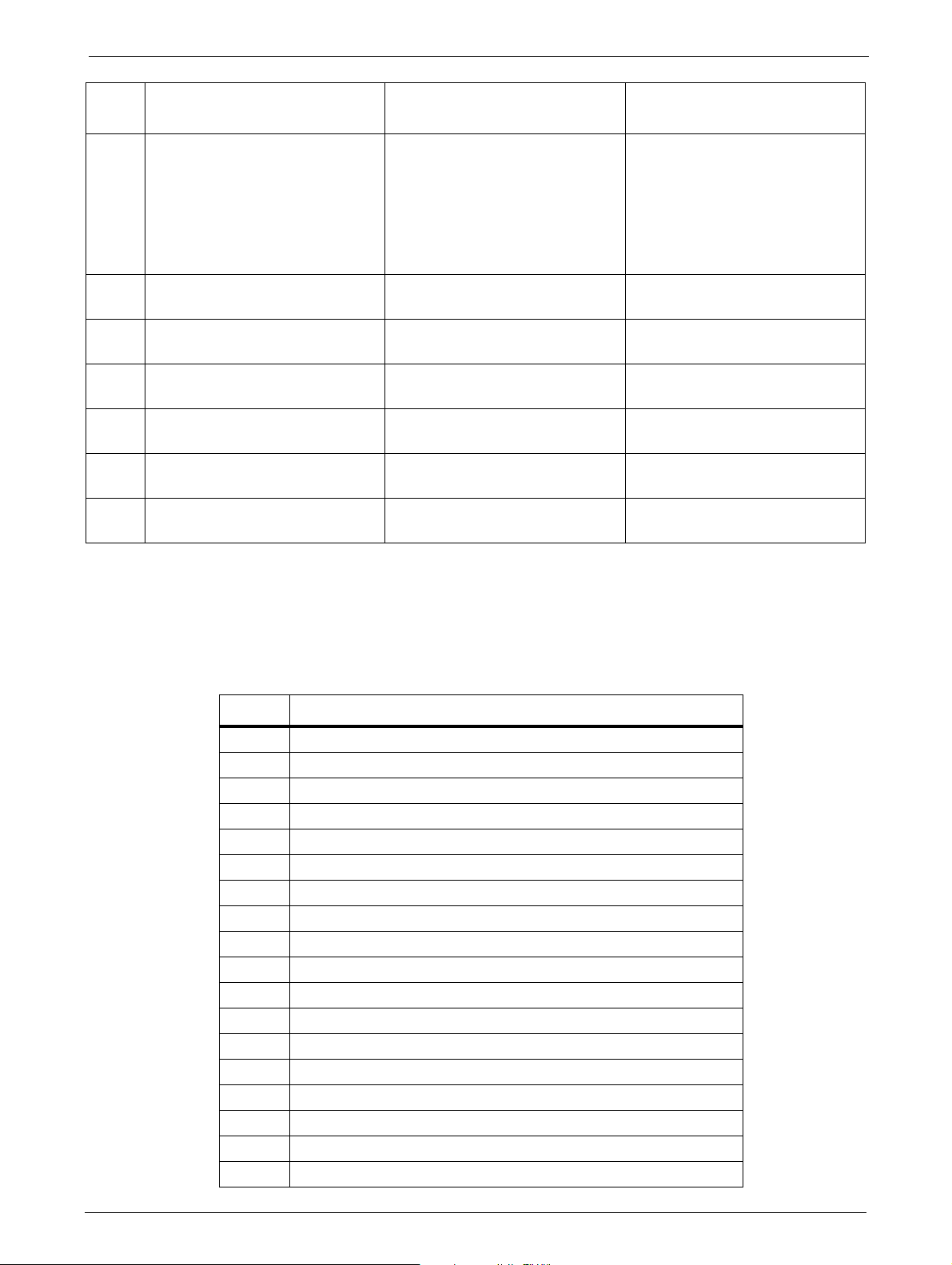
Error Codes
Error
C
ode Description User Action Critical Component Status
F5 Drive Unload Timeout Retry operation; if not successful
Drive has run in a timeout while
unloading a tape
The sub code indicates which
driv
e is affected
F8 Invalid drive command Retry operation; if not successful
F9 Invalid drive parameter Retry operation; if not successful
FA SDCI microcode error Retry operation; if not successful
FB Drive logged out Retry operation; if not successful
FC Internal SCSI command failed
with check
FD Internal SCSI command timeout Retry operation; if not successful
condition
contact technical support
conta
ct technical support
conta
ct technical support
conta
ct technical support
conta
ct technical support
Retry operation; if not successful
contact technical support
conta
ct technical support
Drive probably defective.
Drive leader bent.
Drive initialize repeatedly.
Drive defect (no function).
Drive probably defective.
Drive probably defective.
Drive probably defective.
Drive probably defective.
Drive probably defective.
Drive probably defective.
Sub Error Codes Related to Media Changer
Code Description
01 Mechanical initialization failure
02 Connection to slave media changer failed
03 Error motor initialization
04 Error during gripper close
05 Error slider home positioning
06 Error elevator home movement
07 Error during sled movement to rotation position
08 Error during rotation initialization, get
09 Error elevator initialization
0A Error during rotation to far position
0B Error first sled initialization, move to sensor failed
0C Error during sled movement to rotation position
0D Error during rotation to drive position
0E Error slider initialization, get range failed
0F Error during slider forward movement
10 Error gripper initialization
11 Error during slider home movement
12 Error during rotation to FAR position
, get range failed
range failed
TP-00347-01 99

Code Description
13 Error sled initialization, move to sensor failed
14 Error during sled move - check shipping lock
20 Error Inventory scan
21 Error during gripper close
22 Error slider home movement
23 Error during move gripper to scan pos
24 Error reading barcode label
25 Error during move sled to scan position
26 Error during move elevator to scan position
27 Error during sled preposition movement
29 Error during closing gripper
2A Error slider preposition movement
2B Error during opening gripper
2C Error during sled movement up to sensor
2D Error slider preposition backwards movement
30 Error slot preposition
31 Error during sled movement in <FLMoveRotation> function
32 Command sending to media changer failed
33 Error during elevator movement in <FLMoveRotation> function
34 Error during rotation in <FLMoveRotation> function
35 Error during elevator movement in <FLMoveSled> function
36 Error during sled movement in <FLMoveSled> function
37 Error during sled positioning to sensor in <
FLMoveSled> function
38 Error during sled positioning to mailslot in <FLMoveSled>
fu
nction
39 Error during sled positioning without sensor
3A Error during elevator movement without sensor
3B Error slot position sensor not found
40 Movement to/from slot failed
41 Error during first slider movement
42 Error during first gripper movement
43 Error during second slider movement
44 Error during second gripper movement, get range failed
45 Error during third slider movement, move home failed
46 Error during set hold current to avoid torsion
50 Preposition to drive failed
51 Elevator movement to home sensor failed
52 Sled movement to home sensor failed
53 Error during sled movement to drive position
54 Error during rotation to drive position
55 Error during elevator movement in drive position
56 Error during sled movement to rotation position
Chapter 6: Troubleshooting
100 TP-00347-01
 Loading...