

Page 1
VIII. Loop Installation:
Fail-Safe
Fail-Secure
Power Failure
Loop Failure
Power Failure
Loop Failure
Output State
Call
Call
No Call
No Call
Status
POWER LED
DETECT LED
LOOP FAIL LED
Off
No power or low power
Output Off
Loop OK
On
Normal power to detector
Output On
Open Loop
4 Hz - Two second timing
delay activated
1 Hz - Short ed Lo op
3 Hz - Prior Lo op Failure
of nominal supply vol t age.
Switch
ON
OFF
Factory Default
1
Frequency
(See Table under Frequency Section)
OFF 2 OFF 3 Pulse Mode
Presence Mode
OFF 4 Sensitivity Boost
No Boost
OFF
5
Sensitivity
(See Table under Sensitivity Section)
ON 6 OFF
A =
6 ft
9 ft
12 ft
15 ft
18 ft
21 ft
C =
3 ft
4 ft
4.5 ft
5 ft
5.5 ft
6 ft
1
3
1/8" to 1/4" SAW SLOT
THE WIRE IS
CONTINUOUSLY WOUND
IN THE LOOP SAW SLOT
FOR
NUMBER OF TURNS (2
turns shown)
turn 2
turn 1
REMOVE SHARP
INSIDE CORNERS
FEEDER SLOT
END OF SAW CUT
4
THE WIRES MUST BE
TWISTED TOGETHER
6 TWISTS PER FOOT
FROM THE END OF
THE SAW CUT TO
THE DETECTOR
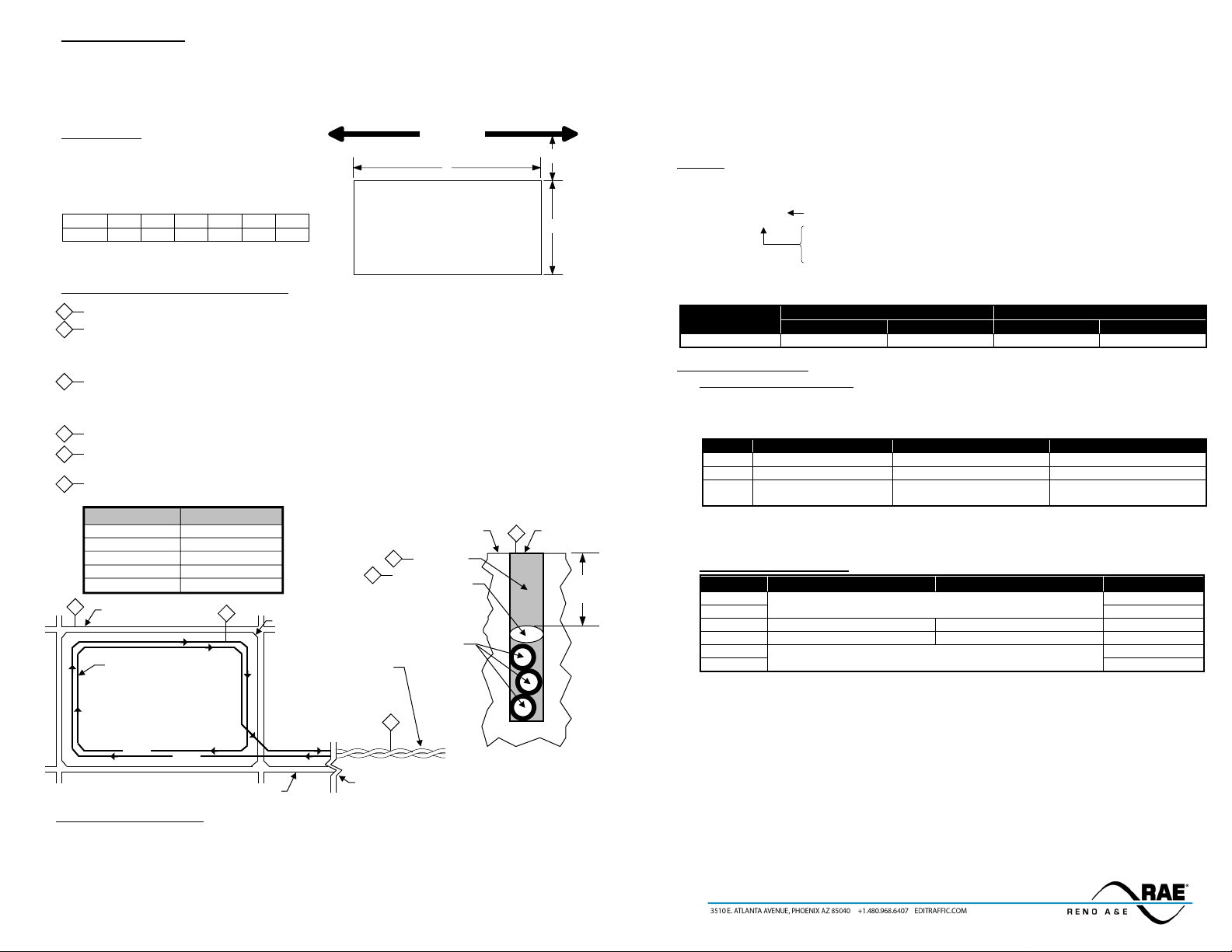
Recommended Loop Wire: Reno LW-120 for 1/8" slots
Reno LW-116-S for 1/4" slots
ROAD SURFACE
MIN
SAW SLOT
SEALANT
BACKER ROD
1" piece spaced
about every 1'
LOOP WIRE
3 TURNS
2
6
5
LOOP PERIMETER
NUMBER OF TURNS
10 feet - 13 feet
5
14 feet - 26 feet
4
27 feet - 45 feet
3
46 feet - 100 feet
2
100 feet and up
1
A B C
A = Loop dimension parallel to the gate
B = Loop dimension perpendicular to the gate
C = Distance of the loop from the gate
SLIDE GATE
The vehicle det ect ion chara cteri sti cs of an ind uc tive loop det ect or a re great ly in flu enced by th e loop size
and proximity to movin g metal ob jects such as ga tes. Vehic les such a s small motorc ycles and high bed
trucks can be reliably detected if the proper si ze loop is selected. If th e loop is placed to o close to a
moving meta l gate, th e detector ma y detect th e gate. The d iagram below is intend ed as a referen ce for
the dimensions that will influence the detection characteristics.
General Rules:
1. The detection height of a loop is 2/3 the shortest leg
(A or B) of the loop. Examp le: Sho rt leg = 6 feet,
Detection Height = 4 feet.
2. As the length of leg A is increased, distance C must
also increase.
3. For reliable detection of small motorcycles, legs A
and B should not exceed 6 feet.
Loop Installation - Saw Cut Type
1 Mark the loop layout on the pavement. Remove sharp inside corners that can damage the loop wire insulation.
2 Set the saw to cut to a depth (typically 2" to 2.5") that ensures a minimum of 1" from the top of the wire to pavement
surface. The saw cut width should be larger than the wire diameter to avoid damage to the wire insulation when placed
in the saw slot. Cut the loop and feeder slots. Remove all debris from the saw slot with compressed air. Check that the
bottom of the slot is smooth.
3 It is highly recommended that a continuous length of wire be used to form the loop and feeder to the detector. Loop wire
is typically 14, 16, 18, or 20 AWG with cross-linked polyethylene insulation. Use a wood stick or rol ler to in ser t th e wi re
to the bottom of the saw slot (do not use sharp objects). Wrap the wire in the loop saw slot until the desired number of
turns is reached. Each turn of wire must lay flat on top of the previous turn.
4 The wire must be twisted together a minimum of 6 twists per foot from the end of the saw slot to the detector.
5 The wire must be held firmly in the slot with 1" pieces of backer rod every 1 to 2 feet. This prevents the wire from
floating when the loop sealant is applied.
6 Apply the sealant. The sealant selected should have good adhering properties with contraction and expansion
characteristics similar to those of the pavement material.
Operating Instructions
Model AX Series
SINGLE CHANNEL LOOP DETECTOR
I. General:
Please verify source voltage before applying power. The model designation indicates the i nput power
required, output configuration, and Fail-Safe / Fail-Secure configuration for t he detector as follows.
Model AX-x-x Blank = Fail-Safe, S = Fail-Secure
3 = 120 VAC
4 = 12 VDC / 24 VDC / 24 VAC
8 = 240 VAC
The detector is factory configured for either Fail-Safe or Fail-Secure opera tion (see unit side label). The
output state of the output relay in eith er Fail-Safe or Fail-Secur e mode is listed in the table below.
II. Indicators and Controls:
i. Power / De tec t / Fail LE D s:
The detector ha s on e green and two red LED indicat ors that are used to provid e an indi cati on of
the detec tor’s power status, output state, and/or loop failure conditions. The table below lists the
various indications and their meanings.
Flash
Note: If the supply voltage drops be low 7 5% of t he nominal level, the POWER LED will turn off, providing
a visual indication of low supply voltage. Model AX detectors will operate with supply voltage as low as 70%
N/A
ii. Front Pa nel D IP Swi tches :
THE REQUIRED
P/N 889-0106-01 4 Model AX Operating Instructions
1"
Page 2
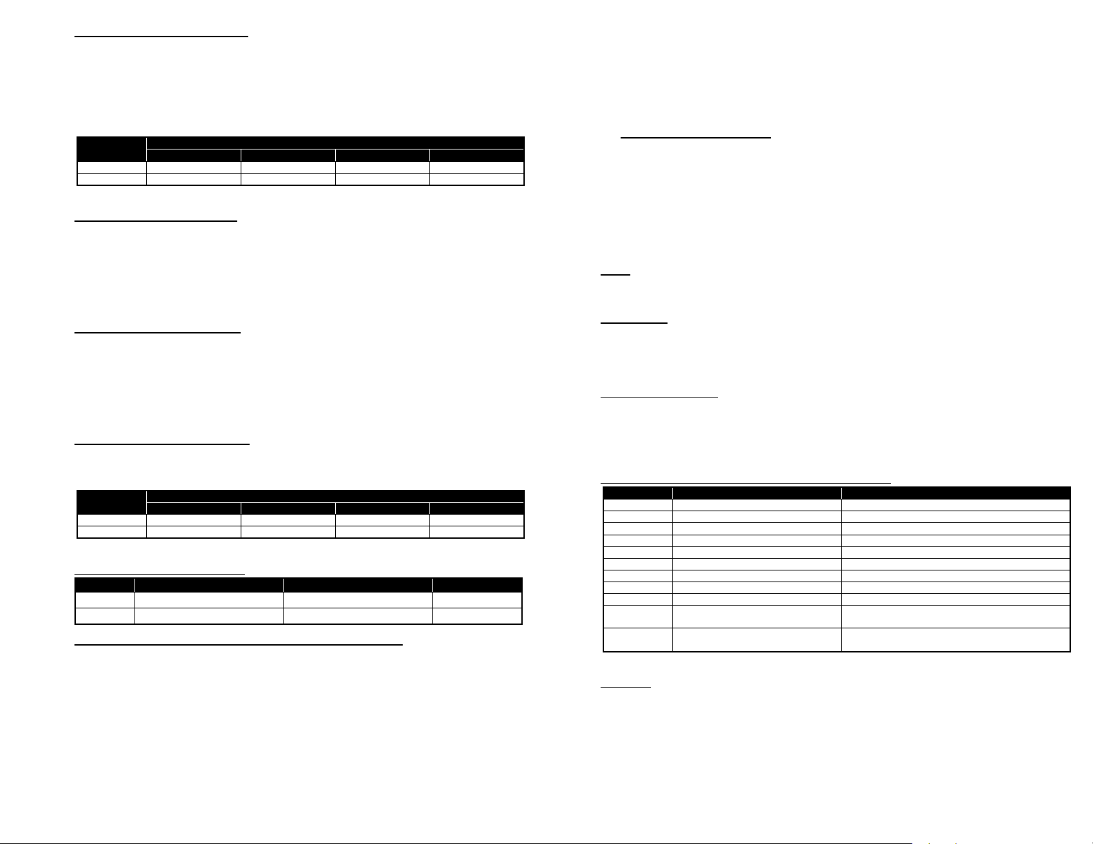
Frequency (DIP Switche s 1 a nd 2 ) :
Frequency
Low (0)
Medium / Low (1)
Medium / High (2)
High (3) *
1
ON
OFF
ON
OFF * 2 ON
ON
OFF
OFF *
* Factory default setting.
Sensitivity Level (-Δ L/L)
0.32% (0)
0.16% (1) *
0.08% (2)
0.02% (3)
5
OFF
ON *
OFF
ON 6 OFF
OFF *
ON
ON
* Factory default setting.
Switch
ON
OFF
Factory Default
1
Exit Pulse or Limited Presence
Entry Pulse or True PresenceTM
OFF
2
Pin
Wire Color
Function
1
Black
AC Line / DC + 2 White
AC Neutral / DC Common
3
Orange
No Connection
4
Green
No Connection 5 Yellow
Relay, Common 6 Blue
Relay, Normally Open (N.O.)
7
Gray
Loop
8
Brown
Loop
9
Red
No Connection
Violet or
Black / White
White / Green or
Red / White
Note: All pin connections listed above are with power applied, loop(s) connected, and no vehicle detected.
In situations where loop geometry forces loops to be located in close proximity to one another, it
may be necessary to select different frequencies for each loop to avoid loop interference, commonly
known as crosstalk. DIP switches 1 and 2 can be used to configure the detector to operate at on e of
four frequencies corresponding to Low, Medium / Low, Medium / Hig h, and High as shown in the
table below.
NOTE: After changing any frequency switch setting(s), the detector must be reset by momentarily
changing one of the other switch positions or pressing the front panel RESET pushbutton.
Switch
Presence / Pulse (DIP Swi t ch 3 ):
The output relay has two modes of operation: Presence and Pulse. When set to operate i n Pres ence
mode (DIP switch 3 OFF), an internal D IP switch can be u sed to select one of t wo presence h old
times; Limited Presence or True Pr esence
TM
. When set to operate in Pulse mode (DIP switch 3 ON),
the internal DIP switch can be used to configure the pulse output to occur when the vehicle enters
the loop detection zone (Pulse-on Entry) or when the vehicle leaves the loop detection zone (Pulseon-Exit). (See the Presence H old Time or Output Relay Pulse Mode s ection below for details.)
The factory default setting is OFF (Presence Mode).
Sensit i vi ty Bo o s t ( D IP Switch 4) :
DIP switch 4 can be turned ON to increase sensitivity during the detect period without changing the
sensitivity during the no detect period. The boost feature has th e effec t of t emp ora r il y i nc rea si n g the
sensitivity setting by up to two levels. When a vehicle enters the loop detection zone, the det ector
automatically boosts the sensitivity level. As soon as no vehicle is detected, the detector
immediately returns to the original sensitivity level. This feature is particularly useful in preventing
dropouts during the passage of high bed vehicles. The factory default setting is OFF (no Sensitivity
Boost).
Sensitivity (DIP Switches 5 and 6):
DIP switches 5 and 6 select one of the four (4) sensitivity levels available as shown in the table
below. Use the lowest sensitivity setting that will consistently detect the sma llest vehicle that must
be detect ed . Do not use a sensitivity level higher than necessary.
Switch
When front panel mounted DIP switch 3 is set to PULSE, one of two pulse output modes can be
selected by means of DIP switch 1 on the two-position, PC board mounted DIP switch (labeled
SW2). Th e Pulse-on-Entry setting (DIP switch 1 OFF) causes the output relay to provide a 250
millisecon d pulse when a vehic le enters the loop detect ion zone. The Pulse-on-Exit setting (DIP
switch 1 ON) causes the output relay to provide a 250 millisecond pulse when a vehicle exits the
loop detection zone.
The factory default setting is OFF (Pulse-on-Entry / True Presence
TM
).
Output Delay (DIP Switch 2):
A two second delay of the output can be activated by setting DIP switch 1 t o the ON position.
Output delay is the time the detector output is delayed after a vehicle first enters the loop detection
zone. If th e two second Output Delay feature is activated, the output relay will onl y be turned on
after two second s have passed with a vehicle continuously present in the loop detection zone. If the
vehicle leav es t he loop det ect ion zone during the two sec ond dela y in terva l, d etec tion is ab orted and
the next vehicle t o enter the loop d etection zone will initiate a new full two second d elay interval.
The detector provides an indication that a vehicle is being detected but that the output is being
delayed, by flash ing th e front pa nel DET LED at a four Hz rate with a 50% duty cycle. The factory
default setting is OFF (no Output Delay).
III. Reset:
Pushing the front panel RESET p ushbutton or changing any DIP switch p osition (except 1 or 2) will
reset the d etector. After changing the frequency selection switches, the detector must be reset.
IV. Call Memory:
When power is removed for two seconds or less, the detector automatically remembers if a vehicle was
present and a Call was in effect. When power is restored, the detector will continue to output a Call until
the vehic le leaves the loop detection zone (loss of power or power dips of two seconds or less will not
bring a gat e arm down onto car s as they wait at the gate).
V. Failed Loop Diagnostics:
The FAIL LED indicates whether or not the loop is currently within tolerance. If the loop is out of
tolerance, the FAIL LED indicates whether the loop is shorted (one Hz flash rate) or open (steady ON).
If and when the loop returns to within tolerance, the FAIL LED will flas h at a three f lashes p er sec ond
rate to indicate that an intermittent loop fault has occurred and has been corrected. This flash rate will
continue until another loop fault occurs, the detector is reset, or power to the detector is interrupted.
VI. Pi n Connections (Reno A & E Wiring Harness Model 802-4):
iii. PC Board Mounted DIP Switche s:
Two Second Delay No Delay
Presence Hold Time or Outp ut Rela y P ulse Mode (DIP Sw i tc h 1 ):
OFF
10
11
When front panel mounted DIP switch 3 is set to PRES, one of two presen ce hold times can be
selected by means of DIP switch 1 on the two-position, PC board mounted DIP switch (labeled
SW2). Lim ited Presen ce and True Presenc e
is present in the loop detection zone. When DIP switch 1 is ON, Limited Presence is selected,
and the detector will typically hold the Call output for one to three hours. When DIP switch 1
is OFF, Tru e P r es enc e
TM
mode is selected, and the detector will hold the Call output as long as
the vehicle is pres ent in the loop detection zone and power i s not removed . True Presence
time applies only for normal size automobiles and trucks and for normal size loops
(approximately 12 ft
2 3
2
to 120 ft2).
TM
modes both provide a Call output when a vehicle
VII. Warnings:
Separately, for each loop, a twisted pair should be created consisting of only two (2) loop wires running
the entire distance from the loop to the detector (including runs through all wiring harnesses) at a
TM
minimum of six (6) complete twists per foot. For trouble free operation, it is highly recommended that
all connections (including crimped connectors) be soldered.
Relay, Normally Closed (N.C.)
No Connection
 Loading...