

Page 1
Digital Quad HDMI Modulator to 2 x DVB-T or ISDB-T MPEG4
User’s Guide
Quad
Page 2

CONTENTS
CONFIGURATION EXTRACTION (CFG)
►INTRODUCTION .......................................... 3
►FEATURES ...................................................3
►TECHNICAL SPECIFICATIONS ................... 4
►RF SPECIFICATIONS ..................................4
►CONNECTIΟΝ & OPERATION ....................5
►PACKAGE INCLUDES ..................................6
►MAIN MENU ............................................8 - 9
►
►CONFIGURATION IMPORT (CFG) ............ 12
►FAST PRE-CONFIG FUNCTION /
50 ID’S SELECTABLE .................................13
►TROUBLESHOOTING ................................ 14
►INSTALLATION EXAMPLE ........................ 15
The CE certificate of the product is available on our webpage, by visiting this link:
https://www.edision.gr/en/support
2
10 - 12
Page 3
►INTRODUCTION
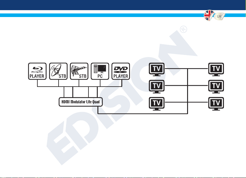
Digital quad-channel FULL HIGH DEFINITION modulator. HDMI signal input from up to four (4) HDMI
sources (Terrestrial & Satellite TV receivers, Cameras, DVD’s, DVR’s, Digital Signage etc) can be converted
to two (2) channels FULL HIGH DEFINITION 1080p, Digital Terrestrial DVB-T or ISDB-T MPEG4 signal
output, in VHF/UHF band. Produces excellent quality signal output, combined with reliable, easy and fast
conguration with the Pre- Cong Function and stable operation in any installation scheme.
►FEATURES
• INPUT signal: 4 Χ HD
• OUTPUT signal: 2 X Digital Terrestrial DVB-T
or ISDB-T MPEG4
• High Video Resolution up to 1080p
• Frequency Range VHF & UHF
• MER more than 35dB
• Adjustable RF Output Level / Default 90dbμV
• Fast Pre-Cong Function / 50 ID’s Selectable
• Backup Cong File by USB
• Software Upgrade by Service Port
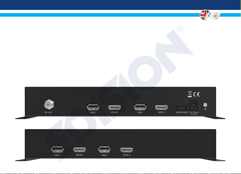
• Ports: 4 X HD IN, RF OUT, 4 X USB, DC 12V,
SERVICE PORT, GROUND
• Four (4) X 4-digit LED Displays
• Low Power Consumption
3
Page 4
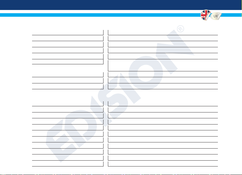
►TECHNICAL SPECIFICATIONS
Power Consumption
Video Encoder
Aspect Ratio
Audio encoder
►RF SPECIFICATIONS
Frequency Range
Impendance
Guard Interval
Constellation
RF Output level
Reed Solomon
Symbol Rate
4
Processor
Memory
HDMI Input
USB Type
Resolution
FEC
Bandwidth
FFT
MER
4 x 200MHZ 32Bits RISC
4 x DDRII 16bit 512Mbits (Embedded) & NOR Flash 32Mbit
4 x HDMI v1.4a
4 x USB 2.0 HOST, Supports Fat32
20W maximum, 100-240V AC to DC power supply unit 12V 3A
MPEG1, MPEG2 MP@HL, MPEG4 SP@L3 to
ASP@L5, MPEG4 AVC HP@level4.1, MP@level4.1
16:9 wide screen, 4:3 letter box, 4:3 pan scan
Up to 1080p@30FPS
MPEGI L1/2, MPEGII LII, AAC LC, HE-AAC v1/v2 (2-CH)
DVB-T or ISDB-T signal / VHF & UHF band
50Ω
1/2, 2/3, 3/4, 5/6, 7/8
1/4, 1/8, 1/16, 1/32
QPSK, 16QAM, 64QAM
2 x 90dBμV, adjustable attenuation 0 ... -14dB, adjustable gain 0 ... +6dB
6MHZ, 7MHZ, 8MHZ
2K, 4Κ, 8K
202, 188, T=8
6MHZ = Up to 2x8000 MBPS, 7MHZ = Up to 2x9000 MBPS, 8MHZ = Up to 2x10000 MBPS
>35dB, at maximum RF level output.
Page 5
►CONNECTIΟΝ & OPERATION
1. Connect up to 4 HDMI Cables from up to 4 HDMI source devices to the respective HDMI Modulator HD
inputs (
2. Connect an RF Cable from RF OUT to the RF Network.
3. Connect the power supply to the HDMI Modulator.
4. Select the desired RF Channel outputs from the modulator display 1 and 3.
5.
6. Proceed with channel scanning on your TV/STB
HD IN 1, 2, 3, 4)
If there are more than one Quad-HDMI Modulator units in the same installation, select ID for each output
channel. The ID selection is made for each quad modulator unit in its own 4 displays, separately in each display.
.
Page 6

►PACKAGE INCLUDES
1. HDMI Modulator lite Quad
2. Power Adapter
3. Mounting screws
4. User Manual
KEY LOCK
Press the key lock and when the green led lights up the
keypad is locked. Press once again to unlock.
HDMI SIGNAL
Connect the HDMI cable to HD ΙΝ and when the green led lights up, the signal is active.
6
LOCK
MENU
/OK
Page 7

►HDMI MODULATOR LITE QUAD FRONT PANEL
7
Page 8

►MAIN MENU
1. The Menu selections for: CHANNEL, RF LEVEL, FACTORY DEFAULTS, TV
2. Each HDMI source input is addressed to its HDMI Modulator.
HD IN 1 = mod 1 (conguration Display)
HD IN 2 = mod 2 (conguration Display)
HD IN 3 = mod 3 (conguration Display)
HD IN 4 = mod 4 (conguration Display)
3. Each HDMI Modulator has its own USB port, for CFG (Cong File) function.
USB 1 = mod 1 (conguration Display)
USB 2 = mod 2 (conguration Display)
USB 3 = mod 3 (conguration Display)
USB 4 = mod 4 (conguration Display)
8
Press Menu/OK to enter the MENU. Navigate through the MENU by using the buttons
“Left” / “Right” in each modulator display separately (MOD1, MOD2, MOD3, MOD4)
MOD1 & MOD2 in pair, produce one COFDM DVB-T or ISDB-T MUX which includes
2 TV channels. e.g. TV-1 & TV-2
MOD3 & MOD4 in pair, produce another COFDM DVB-T or ISDB-T MUX which includes
2 TV channels. e.g. TV-3 & TV-4
IMPORTANT:
STANDARD are made only from Modulator Display MOD1 & MOD3 and automatically
adjust their pair units Modulator Display MOD2 & MOD4, respectively.
Page 9

CH: Shows the current RF
channel output. Use the keys Up
& Down to select the desired RF
channel output.
ID: Shows the current ID. Use
the keys Up & Down to set the
desired ID.
FACT: Factory defaults.
Press key UP to restore factory
defaults.
CFG: Conguration le extraction.
Press key UP to extract the
current conguration to the USB
storage device.
RF: Shows the RF output level.
Use the keys Up & Down to
adjust to the desired RF level.
LCN: Shows the current LCN
type. Use the keys Up & Down to
set the desired LCN type.
SOFT: Shows the SW version.
Use the key
the current SW version.
STAN: Shows the current TV
STANDARD. Using the «Up» and
«Down» buttons you select DVB-T
or ISDB-T.
To save the selected conguration press once the MENU/OK key and conrm with YES
or NO by pressing the LEFT and RIGHT keys and press MENU/OK key once again. The
conguration is being saved, please DO NOT power off the unit! This procedure must be
made separately, in each one of the 4 MODULATOR displays (MOD1, MOD2, MOD3,
MOD4).
Up & Down
to display
9
Page 10
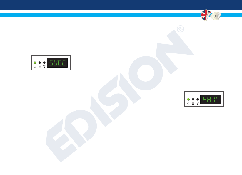
►CONFIGURATION EXTRACTION (CFG)
For an advanced conguration of the HDMI modulator QUAD, you must extract the conguration le one by one for each MODULATOR (MOD1, MOD2, MOD3, MOD4) separately, to a USB drive, modify it and import it again in the respective HDMI modulator. To
extract the conguration le named jedi_cong.txt*, you must connect a USB drive** to
the USB slot, enter the Main Menu, select CFG and press key UP to
extract the le to the USB drive. When the message SUCC appears,
the process has been successfully completed.
*IMPORTANT: Τhe conguration le jedi_cong.txt should not be renamed!
**IMPORTANT: Use only FAT32 partitions! In any other case, the message FAIL
will indicate that the process has not been completed.
10
Page 11

Conguration le details (jedi_cong.txt)
<attribute>value<attribute> Description: Allowed values
<constellation>2<\constellation> Constellation: 0 QPSK, 1 16QAM, 2 64QAM
<channel>43<\channel> RF channel: DVB-T 05-12 & 21-69
ISDB-T 07-13 & 14-69
<bandwidth>8000<\bandwidth> Channel Bandwidth: 6000, 7000, 8000 KHz
<FEC>2<\FEC> FEC: 0: 1/2, 1: 2/3, 2: 3/4, 3: 5/6, 4: 7/8
<FFT>1<\FFT> FFT: 0: 2K, 1: 8K, 2: 4K
<GI>0<\GI> Guard Interval: 0: 1/32, 1: 1/16, 2: 1/8, 3: 1/4
<Name>TV-1<\Name> Channel Name: Max 12 characters
<RF_Level>0<\RF_Level>
<LCN_Type>1<\LCN_Type> LCN Type: 0: ITC(Norway), 1: Italy
<LCN>1<\LCN> LCN: 1 to 999
<TSID>1<\TSID> Transport Stream ID: 1 to 65534
<ONID>1<\ONID> Original Network ID: 1 to 65534
<NetworkID>1<\NetworkID> Network ID: 1 to 65534
<audio_bitrate>3<\audio_bitrate> Audio Bitrate: 0=64kbps, 1=96kbps, 2=128kbps,
3=192kbps, 4=256kbps, 5=320kbps, 6=384kbps
RF Level: 6,4,2,0,-2,-4,-6,-8,-10,-12,-14
11
Page 12

<PCR_GAP>0<\PCR_GAP> PCR Gap: Audio/Video sync max +-5
<audio_format>0<\audio_format> Audio format: 0 MPEG2 L2, 1 AAC MPEG2
<videopid>1002<\videopid> Video PID: 1 to 8000
<audiopid>1001<\audiopid> Audio PID: 1 to 8000
<pmtpid>1003<\pmtpid> PMT PID: 1 to 8000
<serviceID>1000<\serviceID> Service ID: 1 to 9999
<video_bitrate>12500<\video_bitrate> Video Bitrate:
6MHZ = from 0 to 8000
7MHZ = from 0 to 9000
8MHZ = from 0 to 10000
<Netname>EDISION<\Netname> Network Name, Max 12 characters
<TV_Standard>0<\TV_Standard> TV Standard: 0 DVB-T, 1 ISDB-T
(per Modulator, total 2 x 8000)
(per Modulator, total 2 x 9000)
(per Modulator, total 2 x 10000)
►CONFIGURATION IMPORT (CFG)
To import the conguration le jedi_cong.txt, to each MODULATOR (MOD1, MOD2,
MOD3, MOD4) separately, you must save the conguration le one by one in the root
directory* of a USB drive, insert the drive to the respective USB1, USB2, USB3 or USB4
slot and connect the PSU power to your HDMI Modulator. When you see this message CFG, press the MENU/OK
button to conrm the import process. When the process is completed, the unit will reboot with the new conguration!
*IMPORTANT: Use only FAT32 partitions. In any other case, the conguration le will not be read and the
device will reboot normally!
12
Page 13

►FAST PRE-CONFIG FUNCTION / 50 IDS SELECTABLE
This feature enables the user to operate the unit hassle free by automatically setting the appropriate broadcasting table
information [ID] to provide a more convenient installation, easy to adjust anytime with no tools required*! This feature is
important when there are more than one HDMI modulators operating within the same TV coaxial distribution network. Τhe
user should change each unit’s broadcasting table information [ID] to be able for the end user devices to receive the channel.
The HDMI Modulator lite QUAD is pre-congured with the following IDs.
HDMI 1 / mod 1 = ID-01 / TV-1 HDMI 2 / mod 2 = ID-02 / TV-2
HDMI 3 / mod 3 = ID-03 / TV-3 HDMI 4 / mod 4 = ID-04 / TV-4
*IMPORTANT: In order to change the Channel Name, you have to use the CFG function to extract, edit
and load the modied conguration le.
Example of 7* different ID’s:
ID01 ID02 ID03 ID04 ID05 ID06 ID07
Name TV-1 TV-2 TV-3 TV-4 TV-5 TV-6 TV-7
LCN 1 2 3 4 5 6 7
TSID 1 2 3 4 5 6 7
ONID 1 2 3 4 5 6 7
NetworkID 1 2 3 4 5 6 7
Videopid 2101 2102 2103 2104 2105 2106 2107
audiopid 2201 2202 2203 2204 2205 2206 2207
pmtpID 2301 2302 2303 2304 2305 2306 2307
serviceID 2401 2402 2403 2404 2405 2406 2407
*IMPORTANT: 7 sample ID congurations, out of 50 installed in the HDMI Μodulator lite QUAD.
13
Page 14

►TROUBLESHOOTING
The device does not boot
• Make sure the power supply is connected
• Check power supply voltage
I cannot export conguration le
• Make sure your USB drive is working
• Make sure that the le system is FAT32
I get “No signal” message on the screen
• Please check your HDMI cable or the HDMI source device
• Make sure that the HDMI signal complies with the supported standards
The channel number on the list does not appear properly
• Make sure you have selected correct LCN type
• Make sure you have no conicting LCN numbers
The video of the modulator appears to be from another modulator
• Make sure your Fast Pre-Cong ID does not conict with another unit
The sound is not synchronized with the video
• Please adjust the PCR gap each time until you get the perfect A/V sync
For more queries or advanced troubleshooting,
please contact our technical support at support@edision.gr
14
Page 15

2 WAY RF SPLITTER
HD IN 1 HD IN 2
LOCK
MENU
/OK
LOCK
MENU
/OK
HD IN 3 HD IN 4
STBSTB STBSTB
HD IN 1 HD IN 2
STBSTBSTBSTB
LOCK
MENU
/OK
LOCK
MENU
/OK
LOCK
MENU
/OK
LOCK
MENU
/OK
LOCK
MENU
/OK
LOCK
MENU
/OK
HD IN 3 HD IN 4
15
Page 16

www.edision.gr
EDISION HELLAS LTD • FARMAKEIKA - 57001 N. RYSIO • THESSALONIKI - GREECE
 Loading...