

Page 1

Auto Range Digital
Multimeter - USB Interface
OPERATING MANUAL
Functions:
USB interface & software
for the PC
Electrical testing.
Temperature testing from
-5 to +1000°°C.
ORDER CODE: EDI-516-3440K
MODEL DAM060
5163440K_Instructions.qxd 18/09/2009 10:31 Page 1
Page 2

2
CONTENT
1. GENERAL INSTRUCTIONS ......................................................................................2
2. DESCRIPTION ..........................................................................................................6
3. FUNCTIONS DESCRIPTION ......................................................................................9
4. PC SOFTWARE OPERATION ..................................................................................16
5. TECHNICAL SPECIFICATION..................................................................................17
6. MAINTENANCE ......................................................................................................21
7. PACK CONTENT ....................................................................................................22
5163440K_Instructions.qxd 18/09/2009 10:31 Page 2
Page 3

3
Auto Range Digital Multimeter - USB Interface
1.
GENERAL INSTRUCTIONS
This multimeter has been designed according to IEC1010 standards for
electronic measuring instruments with an over-voltage category (CAT II 1000V,
CAT III 600V) and pollution level 2.
To get the best service from this instrument, read carefully this user manual and
respect the detailed safety precautions.
1.1. Precautionary safety measures
Preliminary
• When using this multimeter, the user must observe all normal safety rules
concerning:
- Protection against the dangers of electric current.
- Protection of the multimeter against misuse.
• For your own safety, only use the test probes supplied with the meter provided.
Before use, check the meter and probes are in good condition.
During use
• If the meter is used near noise generating equipment, be aware that the
display may become unstable or indicate large errors.
• Use EXTREME CAUTION when working around bare conductors or bus bars.
• DO NOT operate the meter around explosive gas, vapour, or dust.
• Verify a meters operation by measuring a known voltage and DO NOT use the
meter if it operates abnormally. Protection may be impaired. When in doubt,
have the meter serviced.
• Use the proper terminals, function, and range for your measurements.
• When the range of the value to be measured is unknown beforehand, ALWAYS
set the range dial at the highest position or autoranging mode.
• NEVER exceed the protection limit values indicated in the specifications for
each range of measurement.
• DO NOT touch unused terminals when meter is linked to a circuit.
• Be careful when working with voltages above 60V DC or 30V AC rms.
• When using the probes, keep your fingers behind the finger guards.
• When making connections, connect the common test lead before connecting
the live test lead; when disconnecting, disconnect the live test lead before
disconnecting the common test lead.
• Before changing functions, disconnect the test leads from the circuit under test.
• For all DC functions, including manual or auto range, to avoid the risk of shock
due to possible improper reading, verify the presence of any AC voltages by
first using the AC function. Then select a DC voltage range equal to or greater
than the AC range.
5163440K_Instructions.qxd 18/09/2009 10:31 Page 3
Page 4
• Disconnect circuits power and discharge all high-voltage capacitors before
testing Resistance, Continuity, Diodes, or Capacitance.
• NEVER perform resistance or continuity measurements on live circuits.
• Before measuring current, check the meters fuse and turn off power to the
circuit before connecting the meter to the circuit.
• When carrying out measurements on TV or switching power circuits, always
remember that there may be high amplitude voltage pulses at the test points
which may damage the meter. Use of a TV filter will attenuate any such pulses.
• To avoid the wrong reading or even electric shocks, when the meter displays
, you must change the battery.
• Do not measure voltages above 600V in category III, or 1000V in Category II installations.
• When in REL mode, the 'REL' symbol is displayed. Caution must be used
because hazardous voltage may be present.
• Do not operate the meter with the case (or part of the case) has been removed.
• For continuous protection against fire, replace fuse ONLY with the specified
voltage and current ratings: F200mA/250V.
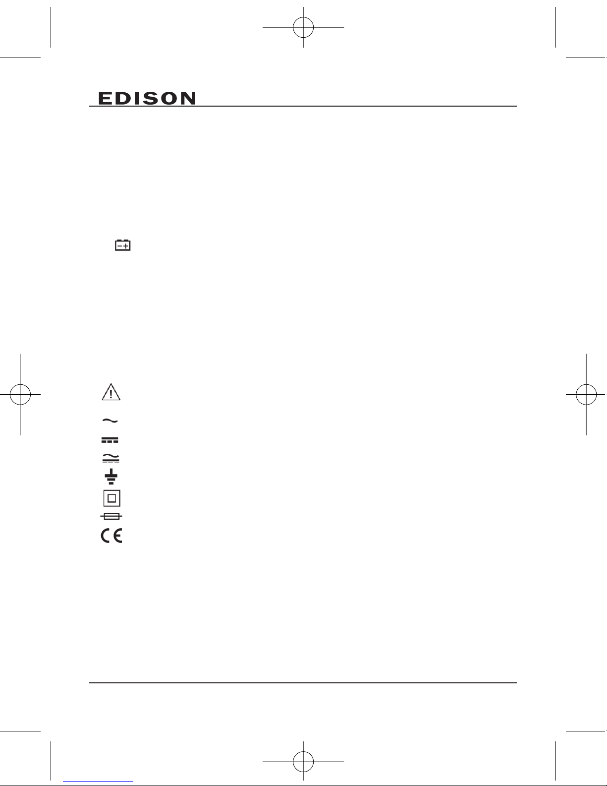
Symbols:
Symbols used in this manual and on the instrument:
CCAAUUTTIIOONN::
Refer to the instruction manual. Incorrect use may result in
damage to the device or its components.
AC (Alternating Current)
DC (Direct Current)
AC or DC
Earth ground
Double insulated
Fuse
Conforms to European Union directives
4
5163440K_Instructions.qxd 18/09/2009 10:31 Page 4
Page 5

5
Auto Range Digital Multimeter - USB Interface
1.2 Maintenance
• DO NOT attempt to adjust or repair the meter by removing the rear case while
voltage is being applied. Please allow a fully qualified technician to investigate
any problems.
• Before opening the meter case, always disconnect test leads from all sources
of electric current.
• Do not use abrasives or solvents on the multimeter; instead use a damp (not
wet) cloth and mild detergent only.
• ALWAYS set the dial to 'OFF' position when meter is not in use.
• If the meter is not going to be used for a long time, take out the battery and do
not store the meter in high temperature or high humidity environment.
1.3 Protection mechanisms
This instrument is fitted with various protection mechanisms:
• Varistor protection for limiting transients of over 1000V at the VΩ terminal.
• A PTC (positive temperature coefficient) resistor protects against permanent
overvoltages of up to 1000V during resistance, capacitance, temperature,
continuity and diode test measurements.
5163440K_Instructions.qxd 18/09/2009 10:31 Page 5
Page 6
6
2.
DESCRIPTIONS
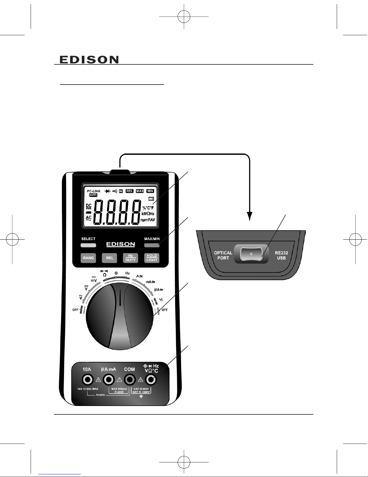
2.1 Instrument Familiarisation
1. LCD display
2. Keypad
3. Rotary switch
4. Terminals
5. USB adaptor port
1
2
5
3
4
5163440K_Instructions.qxd 18/09/2009 10:31 Page 6
Page 7
7
Auto Range Digital Multimeter - USB Interface
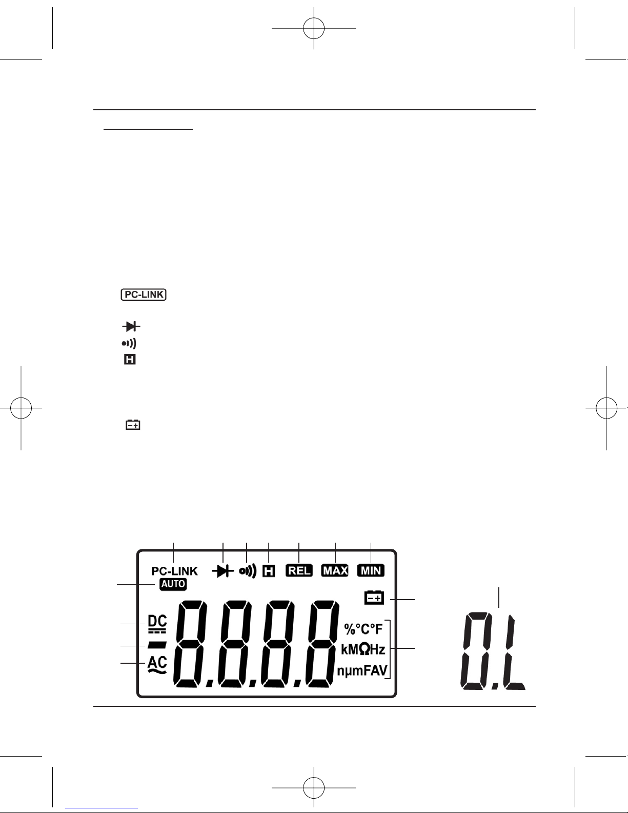
2.2 LCD Display
1. Indicates that
AACC
voltage or current
range is active for testing.
2. Indicates negative readings.
3. Indicates that
DDCC
voltage or
current range is active for
testing.
4. Indicates the meter is in
Autorange mode for the best
automatic test results.
5. Indicates the meter is in
PC data transmission mode.
6. Indicates Diode test mode.
7. Indicates continuity check mode.
8. Indicates Data Hold mode.
9. ‘
RREELL
’ Indicates Relative Measurement mode.
10. ‘
MMAAXX
’ Indicates maximum data.
11. ‘
MMIINN
’ Indicates minimum data.
12. Indicates Low battery (Note: When this symbol appears, it means that the
battery needs to be replaced).
13. Indicates the measurement units in use.
14. ‘
OOLL
’ indicates input is too large for the selected range.
1
2
3
14
12
13
4
5 6 7 8 9 10 11
5163440K_Instructions.qxd 18/09/2009 10:31 Page 7
Page 8

8
2.3 Keypad
SELECT
•In
ΩΩ
position you can switch between Resistance measurement, Diode
test and Continuity check.
•In
AA,, mmAA,, µµAA
position you can switch between DC and AC current.
• Power-up option disables automatic power-off feature.
HOLD/LIGHT
• Press this key to enter and exit the data hold mode.
• Press and hold key for 2 seconds (a beep will sound) and the backlight will
turn ON. If you press again for 2 seconds (a beep will sound) the backlight will
turn OFF.
RANGE
In
VV~~,, VV ,, ΩΩ,, AA,, mmAA
and
µµAA
:
1. Press 'RANGE' to change from Auto (default) to manual mode.
2. Press 'RANGE' to step through the ranges available for the selected function.
3. Press and hold 'RANGE' for 2 seconds (2 beeps will sound) to return to auto ranging.
REL
Press
RREELL
to enter and exit the Relative measurement mode. (This is available in
all ranges except Hz/DUTY).
MAX/MIN
This key is for measuring maximum and minimum value. (This is available in all
ranges except Hz/DUTY).
1. Press it to enter MAX/MIN mode (a beep will sound).
2. Press it again - The LCD will display the maximum value.
3. Press it again - The LCD will display the minimum value.
4. Press and hold it for 2 seconds (2 beeps will sound) and the meter will return
to normal measurement state.
5163440K_Instructions.qxd 18/09/2009 10:31 Page 8
Page 9

9
Auto Range Digital Multimeter - USB Interface
3.
FUNCTION DESCRIPTIONS
3.1 General Functions
HOLD mode
• HOLD mode makes the meter stop updating the display.
• Enabling the HOLD function in auto mode makes the meter switch to manual
mode, but the full-scale range remains the same.
• Data Hold function can be cancelled by changing the measurement mode,
pressing the
RRAANNGGEE
key, or push the
HHOOLLDD//LLIIGGHHTT
key again.
To enter and exit the ‘data hold’ mode:
1. Press
HHOOLLDD//LLIIGGHHTT
key. (This fixes the display on the current value) the letter
'H' will be displayed.
2. A second short press returns the meter to normal mode.
Manual and Auto range mode
The meter has both manual and auto (default) range options.
• In auto range mode, the meter selects the best range for the input detected.
This allows you to switch test points without having to reset the range.
• In manual mode, you select the range. This allows you to override auto range
and lock the meter in a specific range.
• When the meter is in the auto range mode, 'AUTO' is displayed.
To enter and exit the ‘manual’ range mode:
1. Press the
RRAANNGGEE
key. The meter will convert to manual mode. 'AUTO' will not
show on the LCD. Each press of the RANGE key increments the range. When
the highest range is reached, the meter wraps to the lowest range.
NNOOTTEE::
If you manually change the measurement range after entering the Data
Hold modes, the meter exits this mode.
2. To exit the manual ranging mode, press and hold down RANGE key for 2
seconds. The meter returns to auto mode and AUTO is displayed.
Battery Saver
The meter will engage a 'sleep mode' after 30 minutes if it is not used to save
battery life. Be aware data may be lost.
To come out of 'sleep mode':
1. Press the
HHOOLLDD//LLIIGGHHTT
key or rotate the rotary switch to wake the meter up.
2. To disable 'sleep mode' hold down the SELECT key while turning the meter on.
5163440K_Instructions.qxd 18/09/2009 10:31 Page 9
Page 10

10
Relative measurement mode
The meter will display relative measurement in all functions except Frequency.
To enter and exit the relative measurement mode:
1. With the meter in the desired function, touch the test leads to the circuit on
which you want future measurement to be based.
2. Press the
RREELL
key to store the measured value and activate the relative
measurement mode. The difference between the reference value and
subsequent reading is displayed.
3. Press the
RREELL
key for more than 2 seconds to return the meter to normal operation.
3.2 Measurement Functions
AC and DC Voltage measurement
To avoid electrical shock and/or damage to the multimeter, do not
attempt to take any voltage measurement that might exceeds
1000V DC or 1000V AC rms.
To avoid electrical shock and/or damage to the instrument, do not
apply more than 1000VDC or 1000VAC rms between the common
terminal and the earth ground.
The meters voltage ranges are 600.0mV, 6.000V, 60.00V, 600.0V and 1000V.
(AC 600.0mV range only exists in manual mode).
To measure ‘AC or DC’ voltage:
1. Set dial to the '
DDCCVV,, AACCVV orDDCCmmVV
' range.
2. Connect the black test lead to the
CCOOMM
and red test leads to the
VV
terminals
respectively.
3. Connect the test leads to the circuit being measured.
4. Read the displayed value. The polarity of red test lead connection will be
indicated when making a DCV measurement.
NNOOTTEE::
• An unstable display may occur especially at 600mV range, even though you do
not put test leads into input terminals, in this case, if an incorrect reading is
suspected, short the terminals in use to make the display return to zero.
• For better accuracy when measuring DC, offset from the AC voltage, measure
the AC voltage first.
EEXXTTRRAA NNOOTTEE::
• Select the AC voltage range, then manually select a DC voltage range equal
to or higher than the AC range. This improves the accuracy of the DC
measurement by ensuring that the input protection circuits are not activated.
5163440K_Instructions.qxd 18/09/2009 10:31 Page 10
Page 11

11
Auto Range Digital Multimeter - USB Interface
Resistance measurement
To avoid electrical shock and/or damage to the instrument,
disconnect circuit power and discharge all high-voltage capacitors
before measuring resistance.
The meters resistance ranges are 600.0Ω, 6.000kΩ, 60.00kΩ, 600.0kΩ,
6.000MΩ and 60.00MΩ.
To measure resistance:
1. Set the dial to
ΩΩ
range.
2. Connect the black test lead to the
CCOOMM
and the red test lead to the
HHzz
ΩΩVV °°CC
terminals respectively.
3. Connect the test leads to the circuit being measured and read the displayed value.
TTiippss ffoorr mmeeaassuurriinngg rreessiissttaannccee::
• The measured value of a resistor in a circuit is often different from the
resistors rated value. This is because the meters test current flows through all
possible paths between probe tips.
• In order to ensure the best accuracy in measurement of low resistance,
short the test leads before measurement keeping the test probe resistance in
mind. This is necessary to subtract the resistance of the test leads from the
measured resistance.
• The resistance function can produce enough voltage to forward-bias silicon
diode or transistor junctions, causing them to conduct. To avoid this, DO NOT
use the 60MΩ range for in-circuit resistance measurements.
• On 60MΩ range, the meter may take a few seconds to stabilise reading. This
is normal for high resistance measuring.
• When the input is not connected, i.e. at open circuit, the figure 'OL' will be
displayed for the overrange condition.
5163440K_Instructions.qxd 18/09/2009 10:31 Page 11
Page 12

12
Diode Test
To avoid electrical shock and/or damage to the instrument,
disconnect circuit power and discharge all high-voltage capacitors
before testing diodes.
To test a diode out of a circuit:
1. Set the dial to
ΩΩ
range.
2. Press the '
SSEELLEECCTT
' key once to activate (diode test) mode.
3. Connect the black test lead to the
CCOOMM
and red test lead to the
HHzz
ΩΩVV °°CC
terminals respectively.
4. For forward-bias readings on any semiconductor component, place the red test
lead on the components anode and place the black test lead on the
components cathode.
5. The meter will show the approx. forward voltage of the diode.
NNOOTTEE::
In a circuit, a good diode should still produce a forward bias reading of
0.5V to 0.8V; however, the reverse-bias reading can vary depending on the
resistance of other pathways between the probe tips.
Continuity Check
To avoid electrical shock and/or damage to the instrument,
disconnect circuit power and discharge all high-voltage capacitors
before testing for Continuity.
To test for continuity:
1. Set the dial to
ΩΩ
range.
2. Press the 'SELECT' key twice to activate (continuity check) mode.
3. Connect the black test lead to the
CCOOMM
and red test lead to the
HHzz
ΩΩVV °°CC
terminals respectively.
4. Connect the test leads to the resistance in the circuit being measured.
5. When the test lead to the circuit is below 50Ω, a continuous beeping will
indicate it.
NNOOTTEE::
Continuity test is available to check open/short of the circuit.
5163440K_Instructions.qxd 18/09/2009 10:32 Page 12
Page 13

13
Auto Range Digital Multimeter - USB Interface
Capacitance measurement
To avoid electrical shock and/or damage to the instrument,
disconnect circuit power and discharge all high-voltage capacitors
before measuring capacitance. Use the DC voltage function to
confirm that the capacitor is discharged.
The meters capacitance ranges are 60.00nF, 600.0nF, 6.000µF, 60.00µF and
300.0µF.
To measure capacitance:
1. Set the dial to range.
3. Connect the black test lead to the
CCOOMM
and red test lead to the
HHzz
ΩΩVV °°CC
terminals respectively.
3. Connect the test leads to the capacitor being measured and read the
displayed value.
TTiippss ffoorr mmeeaassuurriinngg ccaappaacciittaannccee::
• The meter may take a few seconds to stabilise reading. This is normal for high
capacitance measuring.
• To improve the accuracy of measurements less than 60nF, subtract the
residual capacitance of the meter and leads.
• Below 600pF, the accuracy of measurements is unspecified.
Frequency and Duty Cycle measurement
Do not measure Frequency on high voltage (>1000V) to avoid
electrical shock hazard and/or damage to the instrument.
The meter can measure Frequency or Duty Cycle while making either an AC
Voltage or AC Current measurement.
To measure frequency or Duty Cycle:
1. With the meter in the desired function (AC Voltage or AC Current), press the
HHzz//DDUUTTYY
key.
2. Read the frequency of the AC signal on the display.
3. To make a duty cycle measurement, press the
HHzz//DDUUTTYY
key again.
4. Read the percent of duty cycle on the display.
5. Set the dial to the
HHzz
range.
6. Insert the black test lead into the
CCOOMM
and red test lead in to the
HHzz
input
terminals.
7. Connect the test leads tip in parallel with the circuit to be measured. Don't
touch any electrical conductors.
5163440K_Instructions.qxd 18/09/2009 10:32 Page 13
Page 14

14
8. At frequency measuring status, press Hz/DUTY one time then meter enters
duty cycle measuring status, press it again then return to frequency measuring status.
9. Read the result directly from the display.
NNOOTTEE::
In noisy environment, it is preferable to use shield cable for measuring
small signal.
Temperature measurement
To avoid electrical shock and/or damage to the instrument, do not
apply more than 250VDC or 250VAC rms between the °C terminal
and the COM terminal.
To avoid electrical shock, do not use this instrument when voltages
at the measurement surface exceed 60v DC or 24v rms AC.
To avoid damage or burns. Do not make temperature measurement
in microwave ovens.
To measure temperature:
1. Set the rotary switch to °C range and the LCD will show the current
environment temperature.
2. Insert the 'K' type thermocouples black test lead into the
CCOOMM
terminal and
the red 'K' type test lead in to the
°°CC
terminal (or you can insert it by using
multi function socket), Take care to observe the correct polarity.
3. Touch the object with the thermocouple probe for measurement.
4. Read the stable reading from LCD.
5163440K_Instructions.qxd 18/09/2009 10:32 Page 14
Page 15

15
Auto Range Digital Multimeter - USB Interface
Current measurement
To avoid damage to the meter or injury if the fuse blows, never
attempt an in-circuit current measurement where the open-circuit
potential to earth is greater than 250V.
To avoid damage to the meter, check the meters fuse before
proceeding. Use the proper terminals, function, and range for your
measurement. Never place the probes in parallel with a circuit or
component when the leads are plugged into the current terminals.
The multimeter's current ranges are 600.0µA, 6000µA, 60.00mA, 600.0mA,
6.000A and 10.00A.
To measure current:
1. Turn '
OOFFFF
' power to the circuit. Discharge all high voltage capacitors.
2. Set the dial to the
µµAA,, mmAA orAA
range.
3. Press the
SSEELLEECCTT
key to select '
DDCC AA
' or '
AACC AA
' measuring mode.
4. Connect the black test lead to the
CCOOMM
terminal and the red test leads to the
mmAA
terminal for a maximum of 600mA. For a maximum of 10A, move the red
test lead to the A terminal.
5. Break the circuit path to be tested, touch the black probe to the more negative
side of the break and touch the red probe to the more positive side of the
break. (Reversing the leads will give a negative reading, but will not damage
the meter.)
6. Turn power '
OONN
' to the circuit; then read the display. Be sure to note the
measurement units at the right side of the display (µA, mA or A).
When only the figure 'OL' displayed, it indicates overrange situation and the
higher range has to be selected.
7. Turn '
OOFFFF
' power to the circuit and discharge all high voltage capacitors.
Remove the meter and restore the circuit to normal operation.
PC-Link
The meter has a serial data output function. It can be connected to a PC by USB
interface, so the measured data can be recorded, analysed, processed and
printed by a PC. Before using this function, you need to install the 'PC-Link'
software and then connect the USB driver in your PC.
5163440K_Instructions.qxd 18/09/2009 10:32 Page 15
Page 16

16
4.
PC-LINK SOFT OPERATION
1. First install the PC-LINK software from the CD provided onto your computer.
2. Once the software has finished installing connect the USB driver lead into both
the PC and multimeter.
3. Hold down the Hz/DUTY key while you turn on the meter, the meter will go into
PC-Link mode and the symbol 'PC-LINK' will appear on the LCD. The serial data
output function is then active.
NNOOTTEE::
If you want to enable the serial data output function during measuring, you
have to turn 'OFF' the meter first, then operate according to step 2.
4. Connect the meters OPTICAL PORT and computer USB port with the USB line.
5. Run the PC-LINK software, click the SET menu. Select the System Set. Then
select the COM port in the serial port Select. As for the proper COM port, we
can view it in the device manager by following these steps.
- Right-click the 'My Computer' icon on the Windows desktop, and then click
'Properties'.
- Click the 'Hardware' tab and then click 'Device Manager'.
- Scroll through the list of installed devices till you locate the Ports (Com and
LPT) entry. Click the plus (+) beside this entry to view the installed ports, If no
errors occur, the USB to Serial COM Port (COM x) will appear, COM x is just
the proper port, here x is a specific number.
6. Select the default sampling rate or you can select other desired sampling rate.
7. Now press 'Start' in the PC-LINK software to measure and view the synchronic
data or graph in the software interface.
8. To disable the serial data output function, switch the meter to 'OFF' location first.
9. For more information about the PC-LINK SOFT, please refer to the Help topic
included in the software
5163440K_Instructions.qxd 18/09/2009 10:32 Page 16
Page 17

17
Auto Range Digital Multimeter - USB Interface
5.
TECHNICAL SPECIFICATIONS
5.1 General specifications
• Environment Conditions:1000V CAT. II and 600V CAT. III
• Pollution degree: 2
• Altitude < 2000m
• Operating temperature: 0~40°C, 32°F ~122°F (<80% RH, <10°C non-condensing)
• Storage temperature: -10~60°C 14°F ~140°F (<70% RH, battery removed)
• Temperature Coefficient: 0.1x (specified accuracy) / °C (<18°C or >28°C)
• MAX. Voltage between terminals and earth ground: 700V AC rms or 1000V DC.
• Fuse Protection: µA and mA:
- F 750mA/250V 5 x 20 A
- µF 10A/250V 6.35 x 31.8.
• Sample Rate: 3 times/sec for digital data.
• Display: 3 5/6 digits LCD display. Automatic indication of functions and symbols.
• Range selection: automatic and manual.
• Over Range indication: LCD will display "OL".
• Low battery indication: The ‘ ‘ symbol is displayed when the battery needs
replacing.
• Polarity indication: ‘
------
’ displayed automatically.
• Power source: 9V
• Battery type: 6F22.
• Dimensions: 180(L) x 85(W) x 40(H) mm.
5.2 Measurement specifications
Accuracy is specified for one year after calibration, at operating temperatures of
18°C to 28°C, with relative humidity at 0% to 75%.
Accuracy specifications take the form of: ± (% of Reading + Number of Least
Significant Digits).
VOLTAGE
DDCC VV
RANGE RESOLUTION ACCURACY
600mV 0.1mV ± (0.5% of rdg + 8 digits)
6V 1mV
60V 10mV ± (0.8% of rdg + 5 digits)
600V 100mV
1000V 1V ±(1.0% of rdg + 10 digits)
5163440K_Instructions.qxd 18/09/2009 10:32 Page 17
Page 18

18
AACC VV
1. Frequency range for ACV: 40Hz~400Hz.
2. Response for ACV: Average, calibrated in rms of sine wave.
- Overload protection: 1000V DC or 700V AC rms.
- Input impedance (nominal):
DC voltage: >10MΩ
AC voltage: >10MΩ
- Common mode rejection ratio:
DC voltage: >100dB at DC, 50 or 60 Hz;
AC voltage: >60dB at DC, 50 or 60 Hz
- Normal mode rejection ratio: DC voltage: >45dB at 50 or 60Hz
FREQUENCY (10Hz-1MHz)
• Overload protection: 250V DC or 250V AC rms
RESISTANCE
• Overload protection: 250V DC or 250V AC rms
RANGE RESOLUTION ACCURACY
99.99Hz 0.01Hz
999.9Hz 0.1Hz
9.999Hz 0.001kHz ± (0.1% of rdg + 3 digits)
99.99kHz 0.01kHz
999.9kHz 0.1kHz
RANGE RESOLUTION ACCURACY
600.0Ω 0.1Ω ± (0.5% of rdg + 3 digits)
6.000kΩ 1Ω
60.00kΩ 10Ω
± (0.5% of rdg + 2 digits)
600.0kΩ 100Ω
6.000MΩ 1kΩ
60.00MΩ 10kΩ ± (1.5% of rdg + 3 digits)
RANGE RESOLUTION ACCURACY
600mV 0.1mV
± (3.0% of rdg + 3 digits)
Manual Range only
6V 1mV
60V 10mV ± (1.0% of rdg + 3 digits)
600V 100mV
700V 1V ±(1.5% of rdg + 3 digits)
5163440K_Instructions.qxd 18/09/2009 10:32 Page 18
Page 19

19
Auto Range Digital Multimeter - USB Interface
DIODE TEST
• Test condition: Forward DC current approximately 1mA. Reversed DC voltage
approximately 1.5V.
• Overload Protection: 250V dc or 250V ac rms
CONTINUITY CHECK
• Description: Continuity beeper ≤50Ω.
• Overload Protection: 250V DC or 250V AC rms
TEMPERATURE
• Note: The specifications of temperature don't include thermocouple errors.
• Overload Protection: 250V DC or 250V DC rms.
CAPACITANCE
• Overload Protection: 250V DC or 250V DC rms.
RANGE RESOLUTION ACCURACY
-55°C to 0°C 0.1°C ± (5.0% of rdg + 4°C)
1°C to 400°C 0.1°C ± (2.0% of rdg + 3°C)
401°C to 1000°C 1.0°C ± 2.0% of rdg
RANGE RESOLUTION ACCURACY
60nF 10pF ± (3.0% of rdg + 20 digits)
600nF 100pF
6µF 1nF ± (3.0% of rdg + 10 digits)
60µF 10nF
300µF 100nF ±(5.0% of rdg + 10 digits)
RANGE RESOLUTION ACCURACY
1V 0.001V 1.0% uncertainty
RANGE RESOLUTION TEST CONDITION
600Ω 0.1Ω Open circuit voltage: approx. 0.5V
5163440K_Instructions.qxd 18/09/2009 10:32 Page 19
Page 20

20
CURRENT
DDCC AA
AACC AA
• Frequency Range for AC A: 40Hz-400Hz.
• Response for AC A: Average, calibrated in rms of sine wave overload protection:
- F 10A/600V fuse for 10A range.
- F 750mA/600V fuse for µA and mA ranges.
• Maximum input current:
- 600mA DCor 600mA AC rms for µA and mA ranges.
- 10A DC or 10A DC rms for 10A ranges.
• For measurements >6A, 4 minutes maximum ON to measure 10 minutes OFF;
Above 10A unspecified.
RANGE RESOLUTION ACCURACY
600µA 0.1µA
± (1.5% of rdg + 3 digits)
6000µA 1µA
60mA 0.01mA
± (1.8% of rdg + 5 digits)
600mA 0.1mA
6A 1mA
±(2.0% of rdg + 5 digits)
10A 10mA
RANGE RESOLUTION ACCURACY
600µA 0.1µA
± (1.8% of rdg + 5 digits)
6000µA 1µA
60mA 0.01mA
± (2.0% of rdg + 8 digits)
600mA 0.1mA
6A 1mA
±(3.0% of rdg + 8 digits)
10A 10mA
5163440K_Instructions.qxd 18/09/2009 10:32 Page 20
Page 21

21
Auto Range Digital Multimeter - USB Interface
6.
MAINTENANCE
This section provides basic maintenance information, including fuse and battery
replacement instructions.
Do not attempt to repair or service your Meter unless you are qualified to do so
and have the relevant calibration, performance test, and service information.
6.1 General Maintenance and Cleaning
To avoid electrical shock or damage to the multimeter, do not get
water inside the case. Remove the test leads and any input signals
before opening the case.
Cleaning the multimeter:
• Wipe the case with a soft damp (not wet) cloth and mild detergent.
• DO NOT use abrasives or solvents.
• Dirt or moisture in the terminals can affect readings.
Cleaning the terminals:
• Turn the meter off and remove all test leads.
• Shake out any dirt that may have gathered in the terminals.
• Soak a clean swab or cotton bud with a cleaning and oiling agent (such as WD-40).
• Work the swab/bud around in each terminal until you are happy there
are clean. The oiling agent insulates the terminals from moisture-related
contamination.
5163440K_Instructions.qxd 18/09/2009 10:32 Page 21
Page 22

22
Before replacing the battery and fuses, disconnect test leads from
any circuit under test, turn the multimeter 'OFF' and remove test
leads from the input terminals.
To prevent damage to the meter or personal injury, always replace
the battery or fuse with specified rating.
6.2 Battery replacement
When the battery voltage drops below a usable operation range the symbol
will appear on the LCD display, this indicates that the battery will need replacing.
To do this follow these steps.
1. Set the meter to 'OFF' state.
2. Disconnect test leads from any input terminals.
3. Use the appropriate screwdriver to unscrew the secured back cover. This will
expose the batteries.
4. Replace the battery with a new 9V battery (1604).
5. Replace the battery cover and screw securely back into place.
6. The multimeter should now be fully functional.
6.3 Fuse replacement
1. Set the meter to 'OFF' state.
2. Disconnect test leads from any input terminals.
3. Use the appropriate screwdriver to unscrew the secured back cover and then
the battery cover.
4. Replace the fuse only with an F 200mA/250V fuse.
5. Replace the 2 back covers and screw securely back into place.
6. The multimeter should now be fully functional.
7.
PACK CONTENT
• Digital multimeter
• Test probes
• Temperature sensor probe
• Clamp-on test lead
• USB adaptor
• CD ROM software
• 9V battery (included)
• Instruction manual
5163440K_Instructions.qxd 18/09/2009 10:32 Page 22
Page 23

23
Auto Range Digital Multimeter - USB Interface
5163440K_Instructions.qxd 18/09/2009 10:32 Page 23
Page 24

Edison Products are continuously being developed and improved.
All details and illustrations are for guidance and may be subject to change.
EDISON
The Power Factory, PO Box 14, Wigston, Leicester, England.
ISO 9001 Registered Company
5163440K_Instructions.qxd 18/09/2009 10:32 Page 24
 Loading...