

Page 1
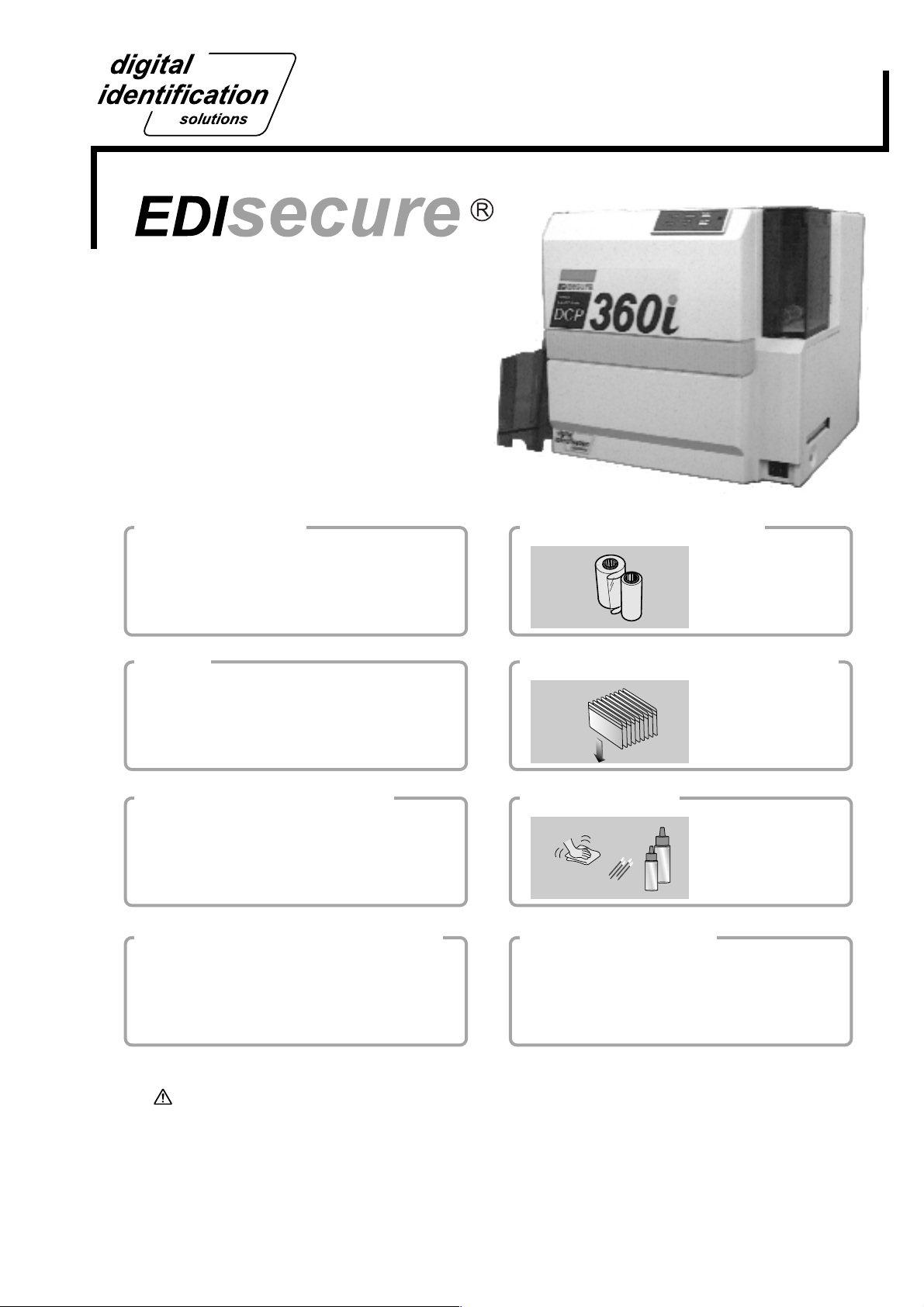
Startup Guide
Setup and Basic Usage of the Printer
Direct Dye Sublimation Printer
Model
DCP360i
Read Me First Changing of Ink Ribbon
Notes for Safe Operation
Before Use
See pages 5 to 8
Setup
Setting Up the Printer
See pages 10 to 17
Installation of Software
Connecting to the Host Computer
Installation of DCP360i software
Checking Connection with the Host Computer
See pages 18 to 19
How to Read the Instruction Manual
Setting / Replacement of Card
Maintenance
Troubleshooting
(Electronic Manual)
See pages 12 to 13
See pages 14 to 16
See pages 21 to 24
See page 20
Thank for purchasing this product.
Please read this manual carefully before use to ensure correct operation.
It is particularly important to read the Notes for safe operation. After reading, retain this
manual carefully for future reference.
The product number is important for quality control. Upon purchase, check the back of
the unit to make sure that the product number is correctly displayed.
Notes about this manual
(1)This manual may not be reprinted in any way without permission.
(2)The contents of this manual, as well as the specifications and design of this product,
may change without notice.
(3)The illustrations used in this manual may differ slightly from the actual product.
See pages 25 to 28
KAT- T189-007
Page 2

Declaration of Conformity
Model Number: DCP360iyyyyy(y=A-Z,0-9 or blank)
Product name: Card Printer
We herewith declare that the above mentioned product complies with the following council
directives and harmonized standards.
Council Directives: 1999/5/EC relating to radio equipment and telecommunications terminal
equipment.
89/336/EEC relating to electromagnetic compatibility.
73/23/EEC relating to electrical equipment designed for use within
certain voltage limits.
Harmonized Standards: EN55022:1998+A1:2000 +A2:2003 Class B
EN55024:1998+A1:2001+A2:2003
EN61000-3-2:2000
EN61000-3-3:1995+A1:2001
EN60950-1:2001
EN50371:2002
EN300 330-2:V1.1.1
EN301 489-03:V1.4.1
Manufacture:
Victor Company of Japan, Limited
2969-2, Ishikawa-cho, Hachioji-shi, Tokyo, 192-8620, Japan
Importer and distributer:
Digital Identifications Solutions Group of Companies.
Teckstraße 52, D-73734 Esslingen, Germany
Tel : (711)341 689 -0 , Fax: (711) 341 689-550
Year to begin affixing CE Marking: 2005
Hachioji-shi, June , 2006
Place, Date Toru Shimizu General Manager-Quality Control
2
Victor Company of Japan, Limited
Page 3
For USA only
NOTE: This equipment has been tested and found to comply with the limits for a Class B digital device, pursu-
ant to part 15 the FCC Rules. These limits are designed to provide reasonable protection against
harmful interference in a residential installation. This equipment generates, uses and can radiate radio
frequency energy and, if not installed and used in accordance with the instructions, may cause harmful
interference to radio communications. However, there is no guarantee that interference will not occur in
a particular installation. If this equipment does cause harmful interference to radio or television reception, which can be determined by turning the equipment off and on, the user is encouraged to try to
correct the interference by one or more of the following measures:
– Reorient or relocate the receiving antenna.
– Increase the separation between the equipment and receiver.
– Connect the equipment into an outlet on a circuit different from that to which the receiver is con-
nected.
– Consult the dealer or an experienced radio/TV technician for help.
NOTE: Changes or modifications not expressly approved by the party responsible for compliance could void
the user’s authority to operate the equipment.
For Canada only
Operation is subject to the following two conditions:
(1)this device may not cause interference, and (2) this device must accept any interference, including
interference that may cause undesired operation of the device.
For EU only
Machine Noise
Sound power level: less than 70 dB (A) according to DIN45635 part 19 (EN27779).
The measurements are to be made according to DIN 45635 part 2019 or EN27779, respectively.
3
Page 4

Contents
Notes for safe operation................................ 5
Before use..................................................... 7
Printer Characteristics ...........................................7
Checking Accessories ...........................................7
Content of Attached CD-ROM............................... 7
Protection of Color Printing Part ............................ 7
Handling the Ink Ribbon and Card ........................ 7
Cautions for Handling ........................................ 7
Storage Method ................................................. 7
Storage and Handling of Card After Printing...... 8
Purchase of Ink Ribbon and Card......................8
Escape Clause ...................................................... 8
Part Names .................................................. 9
(Front / Right).....................................................9
(Rear / Left)........................................................9
(When Printer Door is Open) ............................. 9
Setup........................................................... 10
Location for Installation....................................... 10
Setting Up the Printer .........................................10
Connecting the Laminator................................10
Connecting the Power Cord............................. 1 1
Mounting the Card Stacker .............................. 1 1
Ejection of Card ............................................... 11
Setting the Ink Ribbon...................................... 12
Adjusting Card Thickness ................................14
Setting the Card ............................................... 14
When Using a Magnetic Card .......................... 16
When Using a Contact-type IC Card................ 16
Supply of Card .................................................16
Connecting the USB Cable.................................. 17
Connecting Multiple Printers................................ 17
Checking Connection with the Host Computer
............................................................... 19
How to read the Instruction Manual (Electronic
Manual).................................................. 20
Content of the Instruction Manual (electronic
manual)................................................................ 20
Maintenance................................................ 21
Cleaning the Cleaning Roller...............................21
Cleaning the Thermal Head................................. 22
Cleaning the Fan Filter ........................................22
Cleaning the Card Transport Roller..................... 23
Cleaning the Magnetic Head ...............................24
After Maintenance ............................................... 24
Troubleshooting (Simplified Version)........... 25
Action for Error Code List ....................................25
Removing Jammed Card.....................................26
Feed Jam ......................................................... 26
When there are frequent feed jams ................. 26
Jam inside the printer....................................... 26
A. When card is at the right (near inverter) ...... 27
B. When card is at the left (near printing unit).. 28
C. When card can barely be seen from
the encoding unit.............................................. 28
Jam Inside Laminator....................................... 28
Procedures for Changing Thermal Head ....... 29
Checking After Changing Thermal Head ............. 32
Consumable/Optional Items/Factory defalt . 33
Memo .................................................... 34~35
Installation of Software................................ 18
Connecting to the Host Computer .......................18
Software Licensing Agreement ........................ 18
About software ................................................. 18
Operation Environment .................................... 18
Installation of DCP360i Software.........................18
4
Softwar use permission contract
Page 5
Notes for safe operation
Before you use
Read these notes on safety thoroughly before operating your printer in order to use the unit properly. To use the
software, you will need to accept terms in the Software Licensing Agreement. Please read through the “Software
Licensing Agreement” at the end of this book before use. Once you start using the unit, this manual should be put
aside the unit, or at a convenient place where you can look up the manual any time as you need.
WARNING CAUTION
If you ignore the warning with this mark, and handle
the unit in a wrong way, death or serious injuries may
occur.
WARNING
If the abnormal phenomena as listed below are seen,
immediately stop operating the unit. Continuing
operation may cause a fire or electric shock.
• Smoke or odd smell comes out from the machine.
• Water or metal went into the machine.
• The unit fell to the floor, or the cabinet was broken.
• The power cable is damaged (exposed lead, broken cable,
etc.)
If you see these phenomena, turn off the power, pull out the
power plug, and contact your dealer as soon as possible. Do
not try to repair it by yourself. It is dangerous.
Do not remove the screws, or disassemble or alter
the machine.
• High-voltage components are contained in the unit.
Touching these areas may result in an electric shock.
• Ask your dealer if you want your printer inspected or
repaired.
• Do not remove the external covers of the machine. You may
get an electric shock.
Do not work on the power cable, or give excessive
force on it. Do not put heavy objects such as furniture
on the cable.
• The cable may be damaged, causing a fire or electric shock.
• When you find a defect on the power cable, such as
exposed lead, stop using the unit, and consult your dealer.
Do not use the machine with the power plug inserted
incompletely.
• The machine generates heat due to incomplete contact,
causing a fire or electric shock.
• Do not put many cords on a single plug socket. The power
cords also heats up.
Do not use the machine with dusts piled on the
power plug. Do not put a metallic material adjacent to
the power plug.
• Dusts and metal are conductive, causing a fire or electric
shock.
• Pull out the power plug from the outlet every six months, and
clean the dusts piled on the legs and body of the plug.
If you ignore the caution with this mark, and handle
the unit in a wrong way, injuries or damages to
properties may occur.
Do not use a line voltage other than instructed.
• Using a line voltage or power supply which is not specified
may cause a fire or electric shock.
Do not put foreign materials from the openings of the
machine (e.g., vents, card slots, cassette inlet, etc.)
• Metals, flammable things, and other foreign materials may
cause a fire or electric shock if entering into the machine.
• If these things went into the machine, immediately turn off
the power, pull out the power plug, and ask your dealer to
repair. Do not try to repair it by yourself. It is dangerous.
Do not put a container with liquid in it, or small metal
ornaments and the like on the machine.
• The liquid or metal entering into the machine acts as a
conductor, causing a fire or electric shock.
• If liquid or metal went into the machine, immediately turn off
the power, pull out the power plug, and ask your dealer to
repair. Do not try to repair it by yourself. It is dangerous.
Do not place the machine on a rickety table or
slanting places.
• The machine may fall out of the table or fall over, which may
damage the machine or injure you.
• If the machine is damaged by falling or turnover,
immediately turn off the power, pull out the power plug, and
ask your dealer to repair. Do not try to repair it by yourself. It
is dangerous.
Do not wet the machine with water.
• Using the machine at a place where water splashes on the
machine, or wetting the machine with water (applying,
throwing, or spilling water over the machine) may cause a
fire or electric shock.
• If water entered into the machine, immediately turn off the
power, pull out the power plug, and ask your dealer to repair.
Do not try to repair it by yourself. It is dangerous.
Do not touch the machine with wet hands.
• Touching the machine with wet hands may cause an electric
shock.
Do not touch the power plug during electrical storms.
• Lightning may cause an electric shock.
5
Page 6

Notes for safe operation (continued)
Ground the machine with the attached electric cord
when connecting it to the utility outlet.
• Using a cord other than the one supplied for grounding may
cause an electric shock when the machine fails.
Do not put your head or yourself into the packaging
bag.
• Do not play with the packaging bag. You may suffocate
yourself.
• Give close attention to small children who may want to play
with the packaging bag.
CAUTION
Pull out the power plug before cleaning the machine.
• This is for preventing electric shocks.
Pull out the power plug when you won’t use the
machine for a prolonged period of time to assure
safety.
• Remove the power plug from the outlet for safety when you
won’t use the machine for a long time.
Do not move the machine with the power cable and
other electric cables connected.
• The cables may be damaged while being moved, which may
cause a fire or electric shock.
• You may stumble over the cable and get injured.
Do not move the machine with objects placed on it.
• They may fall on you and hurt you.
Do not put heavy objects on the machine.
• They may fall on you and hurt you.
Do not block the vents.
• Heat generated inside the machine cannot escape, which
may cause a fire.
Inspection
• Ask you dealer or a qualified person to inspect the machine,
typically once every two to three years. Operating the
machine with dusts piling on the components for a prolonged
period of time may cause a fire or a malfunction of the
machine. It will be particularly effective to inspect the
machine before wet rainy season. Consult your dealer on
the costs of inspection.
Do not use the machine while it has a fault.
• Do not use the machine while it has a fault, as this may
cause a fire or electric shock.
• Immediately turn off the power, pull out the power plug, and
ask your dealer to repair. Do not try to repair it by yourself. It
is dangerous.
Do not put the machine at a place where it becomes
excessively hot.
• The surface and internal components may deteriorate. Also
there is a danger of a fire. Special care should be taken for
exposure to direct sunlight or a heater adjacent to the
machine.
Hold the body of the power plug when pulling it out.
• Do not pull out the plug by holding the cable. The cable may
be broken or damaged which may in turn cause a fire or
electric shock.
Do not touch the power plug with a wet hand
• You may get an electric shock.
Do not lay the power cable near the heating
equipment.
• The covering of the cable will melt due to heat from such
equipment, which may cause a fire or electric shock.
Be careful of jamming your hand or fingers in the
card cassette or printer door.
• Replace the ink ribbon or remove jammed cards with care
not to jam your hand or fingers in the mechanism, which
may cause an injury.
Do not use a power cable other than the specified
cable for connection.
• If you use an unspecified power cable for connection or
extension, heat may accumulate in the cable, causing a fire.
Do not put the machine at a place where it will be
wet with steam (e.g., from a humidifier), or at a
excessively humid or dusty place.
• The oil, water and dusts act as conductors, which may
cause a fire or electric shock.
6
Page 7

Before use
Printer Characteristics
This card printer prints high quality full-color images
equivalent to photographs using dye sublimation printing
on standard-size (ISO7810 compliant) PVC cards.
Printing can be done on both sides of the card.
Able to print maximum of 180 cards per hour. (For
Standard mode and single-sided printing)
Able to add on laminating function by connecting to
the optional Laminator unit (ILU).
Checking Accessories
Check the accessories that come with this printer when
unpacking.
Startup Guide (this book) x 1
*Besides this book, Instruction Manual (electronic
instruction manual) is available on the attached CDROM.
Attached CD-ROM......................................... x 1
Power Cord:
AC 120V type (For North America)(250cm)x 1
AC 200V type (For Europe)(250cm)...........x 1
*The supplied power cord, instruction manual and
attached CD-ROM vary depending on the shipment
destination and product model.
Cleaning Card (for card transport roller) · · · · x 1
Card Stacker · · · · · · · · · · · · · · · · · · · · · · · · · x 1
Ink Ribbon Cassette · · · · · · · · · · · · · · · · · · · x 1
Card Cassette · · · · · · · · · · · · · · · · · · · · · · · · x 1
Cleaning Unit · · · · · · · · · · · · · · · · · · · · · · · · · x 1
Protection Card · · · · · · · · · · · · · · · · · · · · · · · x 1
USB Cable(200cm) · · · · · · · · · · · · · · · · · · · · x 1
Content of Attached CD-ROM
Instruction Manual (Electronic)
DCP360i Printer Driver
DCP360i Status Monitor(Printer Monitoring/Setup Tool)
DCP360i Printer Driver Instruction Manual
DCP360i Status Monitor Software Instruction Manual
Handling the Ink Ribbon and Card
Cautions for Handling
Pay attention to the following when handling the ink ribbon
and card.
• Use of distorted or damaged card will result in card
transport error.
• Touching the ink ribbon or printed surface of the card
directly with your hand will result in uneven print density.
• Attachment of foreign objects to the printed surface may
result in missing prints.
Change or replenish your ink ribbon and card in a clean
environment.
• Electrostatic discharge on the ink ribbon and card may
result in errors. Refrain from activities that will generate
static electricity, such as rubbing the cards.
• When replacing or replenishing old ink ribbons or cards
with a new one that is stored under a low temperature,
leave it for more than one hour in the ambient temperature
where the printer is used. Using it directly will result in
condensation, causing printing error and breakdown.
Storage Method
The storage conditions of ink ribbon and card can greatly
influence the print quality. Choose the following type of
places for storage.
Storage environment
Temperature: 5 °C to 25 °C
Relative humidity: 40 % to 60 %
Storage Place
Avoid storing at the following places as it may result in
ink ribbon and card degradation.
• Locations with direct sunlight
• Locations with high temperature and humidity
• Locations near organic solvent and diazo copying machine
Storage period
Ink ribbons should be used within a half year of
purchase. For cards, please consult the dealer from
which they are purchased.
Protection of Color Part
Be sure to carry out protective layer (OP) printing or
laminating in order to protect the print part that performs
color (YMC ink) printing.
7
Page 8
Before use (continued)
Storage and Handling of Card After Printing
Avoid storing at locations with direct sunlight, high
temperature and humidity.
Contact with the following chemicals and stationery may
also result in discoloration or fading of the card.
• Organic solvents such as alcohol, film cleaner and diazo
copier.
• Soft PVC file, document case, pass holder, eraser, etc.
• Hairdressing products, cosmetics, etc.
Purchase of Ink Ribbon and Card
Consult your dealer for any queries regarding the ink
ribbon and card.
Make sure to use parts as specified below.
Ink Ribbon
Use only specific ink ribbons.
Refer to the page 33 on “Optional Items” in this manual
for the product names.
CAUTION
problems occurred as a result of using ink ribbons other
than the types specified.
We do not bear any responsibility for
Escape Clause
We do not provide compensation for any malfunction
during card printing caused by breakdown of the
machine, ink ribbon defects or card characteristics.
In addition, we also do not provide compensation for
insufficient print quality, which are not agreed in
advance. Please evaluate carefully beforehand.
Card Material
Some card material may not be suitable for printing.
Using a contact-type IC card other t han those specified
by the dealer, may cause damage to the thermal head.
For details on the specifications about card material
or others, consult the dealer in advance
Version upgrade
The following defects may occur as a result of the ver
sion upgrade for the firmware of the printer, the printer
driver and the DCP360i status monitor
• The operation of the printer or application software be-
comes unstable.
• Defects in print result occurs.
Card Specifications
ISO/IEC 7810 type ID1 (dimensions) :
equivalent product
ISO/IEC 7811-2 (Magnetic stripe) :
equivalent product
ISO/IEC 7816 (IC card) : equivalent product
CAUTION
may not be suitable for printing.
The use of contact IC cards other than the type specified
may result in breakdown of the thermal head.
Consult your dealer beforehand on the material and other
specifications of card to be used.
Depending on the material, some cards
• Print color or shade differs.
• The performance of reproducing fine letters, changes.
• Others
Be sure to retain a copy of the current version when
performing version upgrade. Reinstall the previous ver
sion immediately if these problems occur. We are not
liable for any damage such as defective cards or inter
ruptions during printing as a result of the version up
grade.
8
Page 9
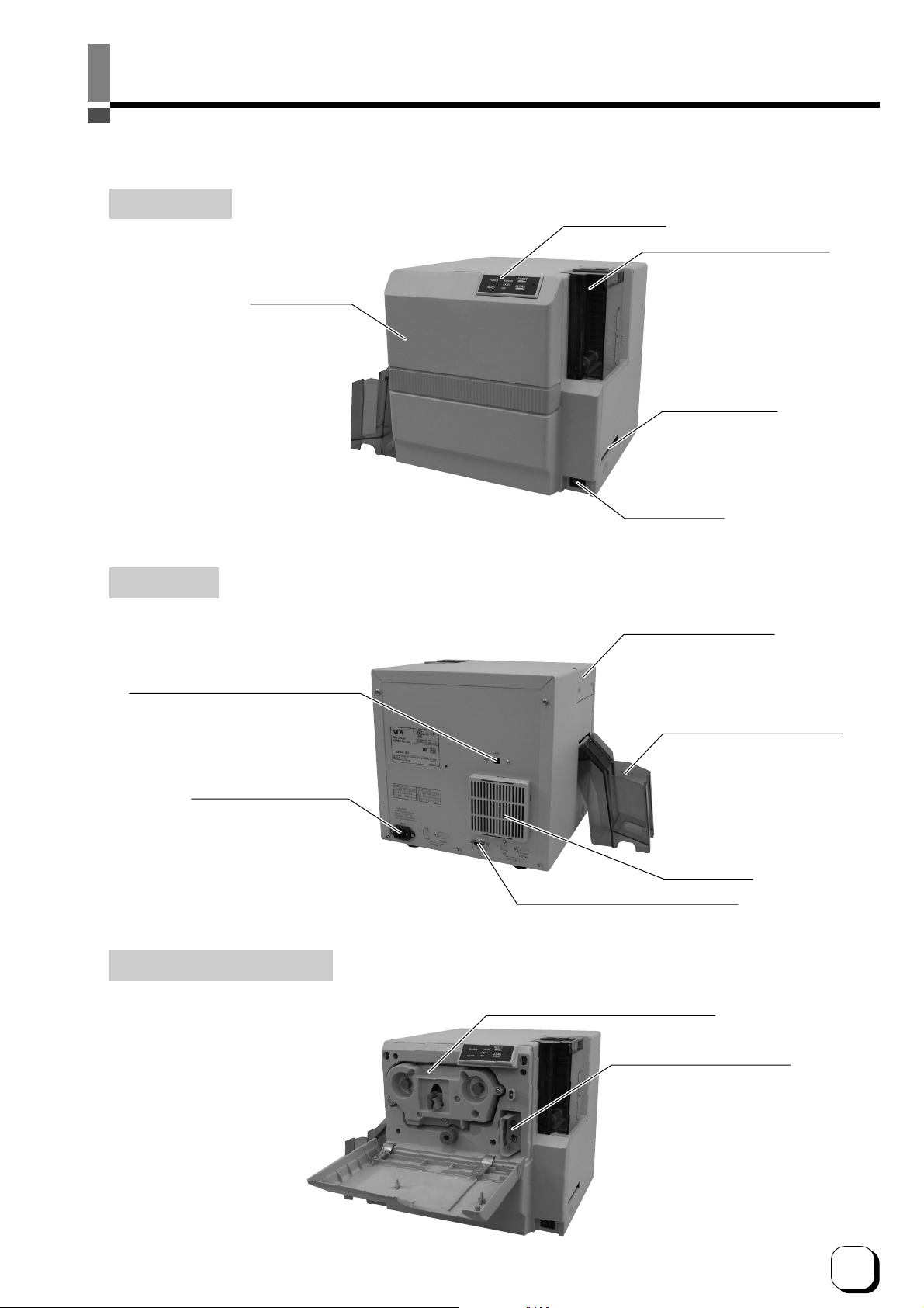
Part Names
(Front / Right)
(Rear / Left)
Control Panel
Card Cassette (Accessory)
Printer Door
NG Card Outlet
Power Switch
Head Exchange Door
USB Cable Connection Terminal
Power Input Terminal
(When Printer Door is Open)
Card Stacker (Accessory)
Filter Cover
Laminator Connection Terminal
Ink Ribbon Cassette (Accessory)
Cleaning Unit (Accessory)
9
Page 10
Setup
Location for Installation
The performance of card printers is greatly influenced by
the environment of the installation location.
Do not install at the following locations.
• Dusty Location
The cleanliness level of location where the printer
is used should be compliant with ISO14611-1 Class
8. Different from the common type of paper printers,
dusty locations will result in uneven print density
and breakdown of the dusty thermal head. Switch
off the printer’s power when no card is being printed.
Fine dust will be collected inside the printer after
leaving the power on for a long time, resulting in
uneven or dirty print.
• Locations with strong vibrations and shock
• Locations exposed to direct sunlight
• Locations where there is possibility of foreign objects
such as metal pieces entering the printer
• Locations against the wall with poor ventilation
• Unstable and inclined locations
• Locations which easily give rise to static electricity
such as carpeted rooms
• Locations which easily give rise to condensation
inside the printer such as places near the cooler,
humidifier or stove
Setting Up the Printer
Connecting the Laminator
An optional laminator is available for this printer. A special
connection cable is required to connect this unit. Consult
your dealer for more details.
WARNING
Install and uninstall the laminator only after
switching off the power of the printer as well
as other devices that are connected to it and
Electric
shock
pulling out the plug from the power outlet.
Failure to do so may result in danger of
electric shock!
Use the dedicated unit and cable when
installing the laminator. Failure to do so may
result in breakdown or electric shock and fire.
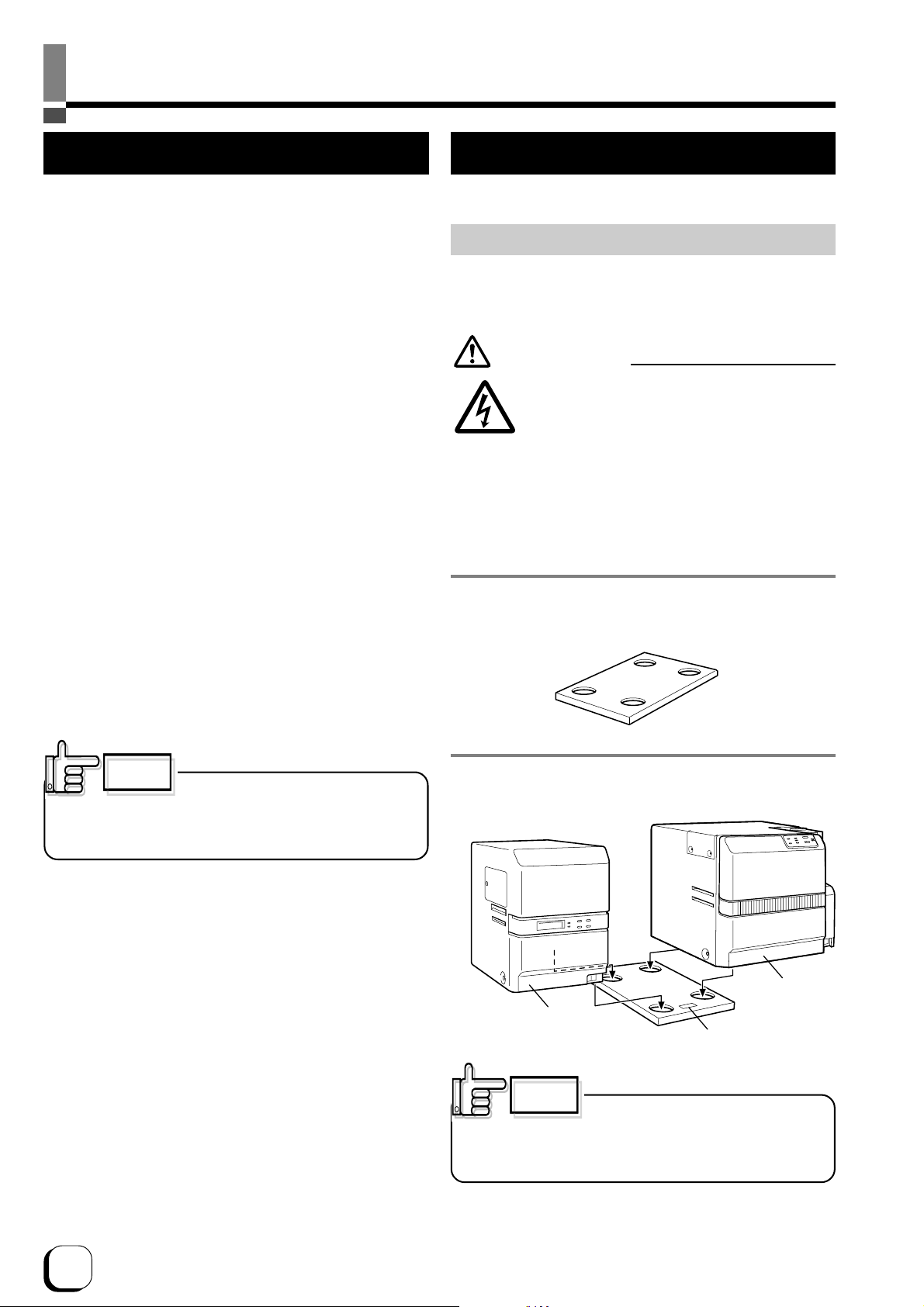
1. Set up the unit coupler plate which comes with the
laminator (optional).
Temperature and humidity of room where printer is
installed should be as follows.
Temperature : 15 °C to 30°C
Humidity : 35 % to 70 %
CAUTION
Using the printer in an environment
beyond the above range may cause printing problems due
to decrease in print density at low temperature and distorted
card and creased ribbon at high temperature.
There are ventilation holes for cooling at the back of the
printer. Place back more than 10 cm away from the
surrounding wall. Additionally, ensure that there is at least
an allowance of 10 cm between the right end of the printer
and the wall so that cards can be discharged from the NG
Card Outlet. Do not place any object above the printer.
2. Insert the printer and laminator into the hole.
Printer
Laminator
(ILU)
Front
CAUTION
If the mounting is uneven, the card will
not be transported smoothly. Be sure that the units fit in
properly. Always install the unit at a horizontal and hard
surface.
(DCP360i)
10
Page 11
Setup (continued)
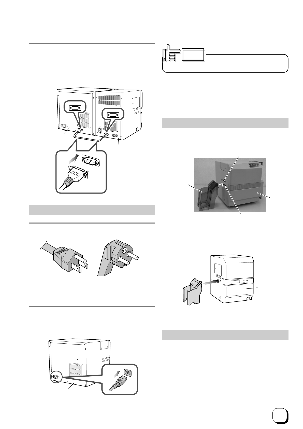
3. Connecting a cable (optional) between units
Insert the cable into the “LAMINATOR” external connection
terminal at the printer and the “PRINTER” external
connection terminal at the laminator, followed by fastening
the cable with the screws provided.
LAMINATOR
PRINTER
Printer
(DCP360i)
Laminator
(ILU)
CAUTION
Always use a dedicated power supply
with earth terminal for the power outlet.
Use AVR (Automatic Voltage Regulator) when there is
possibility of voltage variation. Use of an uninterruptible
power source instead of AVR is recommended when there
is possibility of momentary power interruption.
Mounting the Card Stacker
Pull the tab of the Card stacker at the stacker mount of
the printer.
Card Outlet
Card Stacker
(Accessory)
Connecting the Power Cord
1. Check the plug.
• For AC 120V type • For AC220-240V type
(North America) (Europe)
* The detached power cords vary according to model
and country of purchase.
2. Insert the power cord into the power input terminal
at the back of the printer, followed by plugging the
other end to the power outlet..
Printer
(DCP360i)
Card Stacker mount
When connecting the laminator, pull the tab of the card
stacker at the stacker mount of the laminator card.
Laminator
(ILU)
The card stacker can hold about 100 cards that are
0.76mm in thickness.
Ejection of Card
A properly printed card will be ejected to the card stacker.
If cards remain inside the printer when the power is on or
the printer is being initialized, or if some abnormal situation
occurs with magnetic cards or IC cards, those cards will
be ejected from yhe N.G. Card Outlet on the right side of
the printer.
Printer
(DCP360i)
Connect the power cord to the power outlet in the same
way when connecting the laminator.
11
Page 12
Setup (continued)
Setting the Ink Ribbon
CAUTION
Do not touch the inked surface with your
hands.
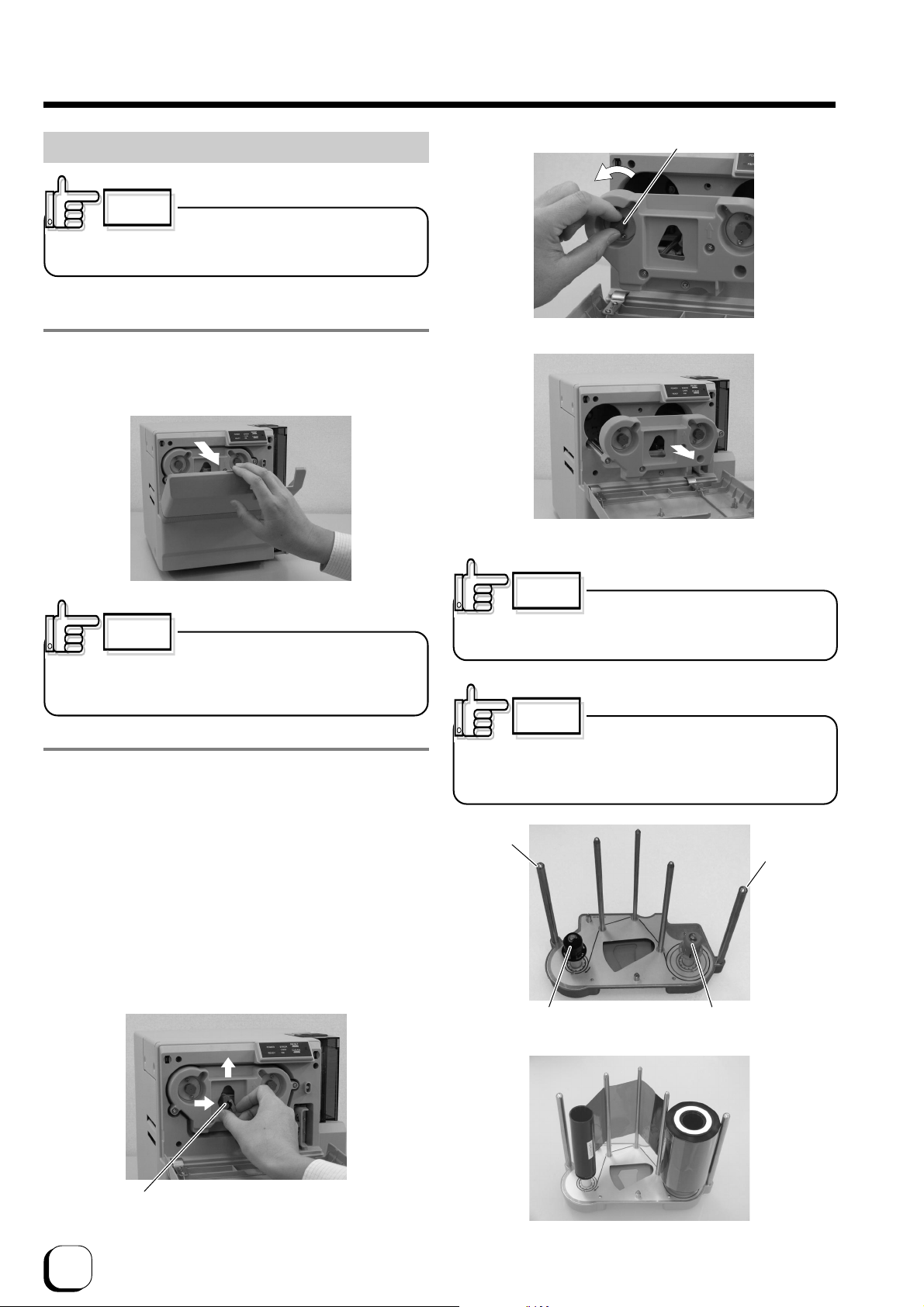
1. Place your fingers on top of the printer door and open
towards you.
Open slowly while supporting with your hands.
Knob
Remove ribbon sags
Remove ink ribbon cassette
CAUTION
Do not install the ink ribbon on top of
the printer door. Do not rest your elbow or place heavy
objects on top. Doing so may damage the printer door.
2. Remove the ink ribbon cassette
Hold the release lever with fingers, and 2 lift the lever
(1)
to unlock.
* Exchanging ink ribbons:
Upon ensuring that the ink ribbon is pulled out by about 3
cm, turn the knob on the ink ribbon cassette in the direction
indicated by the arrow to tighten the ribbon sag.
Remove the ink ribbon cassette while supporting it with
both hands.
Stand the ink ribbon cassette on a flat and firm surface.
Remove any used ink ribbon.
CAUTION
When the ink ribbon is installed, be
careful not to drop it into the inner section when pulling out
the cassette.
CAUTION
When removing the cassette for
cleaning, always stand it as shown in the photo below.
Allowing the inked surface to touch the ground will make
the ink ribbon dirty and cause malfunction.
Shaft
Shaft
Bobbin holder
(Taking up)
Bobbin holder
(Unused)
12
2
1
Release Lever
Unlock
Page 13
Setup (continued)
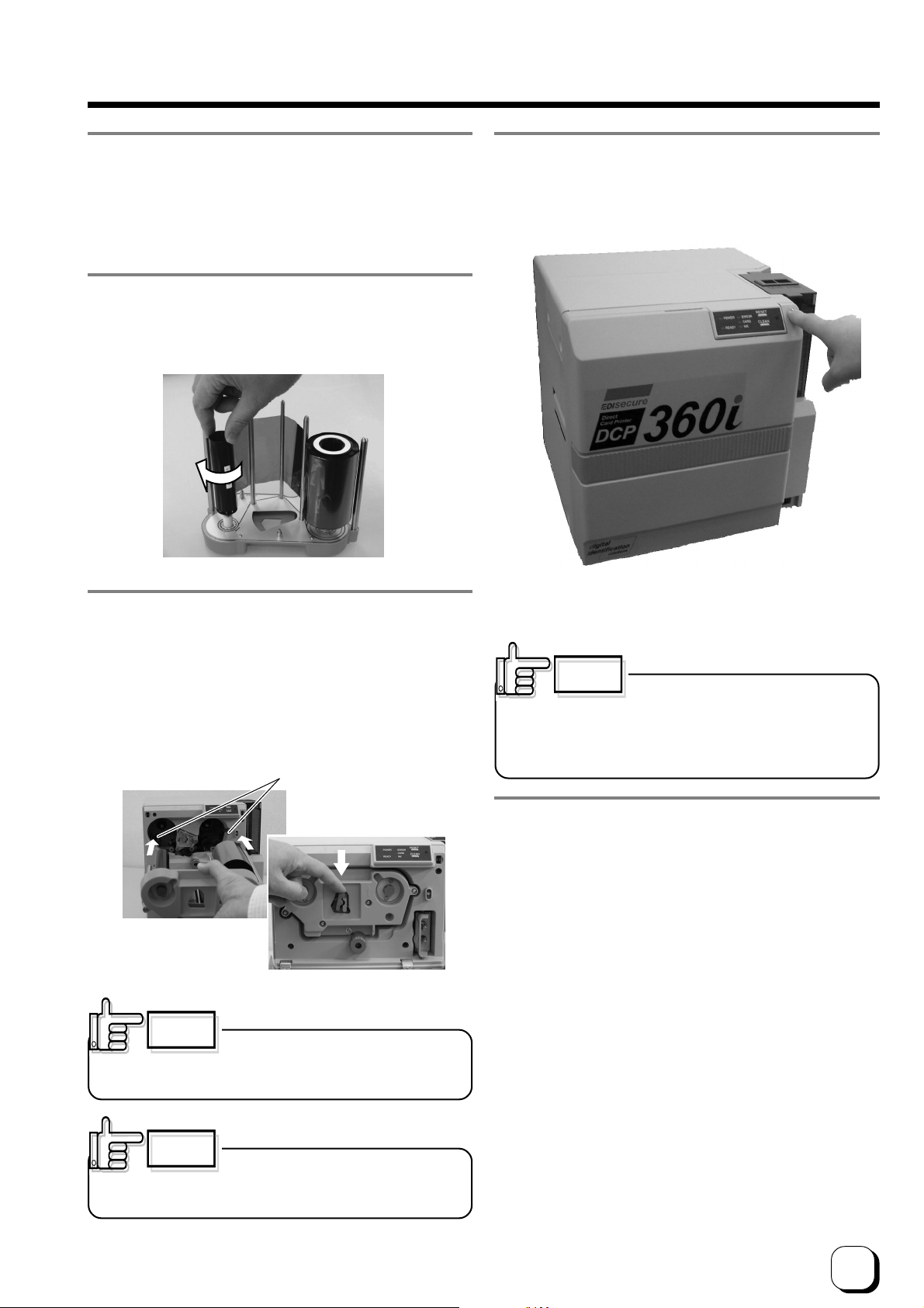
3. Insert ink ribbon into the ink ribbon cassette
With the inked surface facing the outside (inner side rolled
into the bobbin holder), stretch along the 3 shafts and
insert all the way into the bobbin holder.
4. Remove ink ribbon sags
Turn the taking up bobbin in the direction of the arrow to
remove any ink ribbon sag.
6. Close printer door.
Shut the printer door tightly by pressing on the top right
section of the printer door.
5. Insert ink ribbon cassette along the guide rail
While making sure that the ink ribbon does not sag, insert
the ink ribbon cassette all the way in along the guide rail
and push down the lever to lock the ink ribbon cassette.
If it is not so smooth to push down the lever, pull out the
ink ribbon cassette once ,insert it again and push down
the lever while pushing the ink ribbon cassette.
Guid rail
Ensue to fit the ink ribbon
cassette shaft firmly into
the guide rail.
CAUTION
If the ribbon sags, it will result in jammed
ink ribbon and blurred color caused by wrinkles when the
ink ribbon cassette is inserted.
CAUTION
To prevent damage, the printer door is
made in such a way that it cannot be closed properly when
the ink ribbon cassette is not locked or when the ink ribbon
cassette is not inserted. Closing the printer door by force in
such a case may damage the device.
7. Checking
When ink ribbon is changed with power on, the printer
will automatically initialize once the printer door is closed.
If printer power is off, it will start to initialize once it is
switched on.
Check that initialization is carried out properly and the
READY LED (green) is illuminated on the printer control
panel.
CAUTION
Inserting ink ribbon cassette by force
when the guide shaft is not properly placed in the guide rail
may damage the device.
13
Page 14

Setup (continued)
Adjusting Card Thickness
This printer can print cards with thickness between 0.25
mm to 1.00 mm. Default thickness is adjusted to 0.76mm.
1. Remove card cassette
Lock the card cassette cover by moving the slider on the
top of the card cassette to LOCK.
During printing, when the card is not discharged from the
card cassette, adjust the Card separator adjustment position
clockwise, one scale at a time. If 2 cards are discharged,
adjust the Card separator adjustment position anticlockwise.
When cards of different thickness are used frequently, it
is recommended that you purchase an additional card
cassette based on the thickness of the card. Refer to
Optional Items (see p.33) regarding purchase of card
cassettes.
Setting the Card
Get ready the specified cards from your dealer.
CAUTION
Stains such as fingerprints on the printed surface will result
in printing error. Use lint-free gloves (optional) when
handling the card.
Insert the card in an environment that is not subject to
excessive dust.
Lift the card cassette up by about 1cm and slide to the
right to remove the cassette.
2
1
2. Adjust the Card separator
Insert the tip of a ball pen etc, into the hole on Card
separator of the card cassette and turn slowly to adjust to
the thickness of your card.
1. Removing card cassette cover
Unlock by moving the slider on the top of the card cassette
to OPEN. Lift the cover.
Top View of Printer
Slider
Front View of Printer
Cover
14
Ball pen etc.
Card separator
Page 15

Max line
Properly
aligned
Memo
Setup (continued)
2. Insert card
Card cassette can hold about 100 cards of 0.76mm in
thickness.
CAUTION
cards are inserted. Check to ensure that they are kept below
the MAX line.
CAUTION
cards are not properly aligned. Check to ensure that they
are properly aligned.
Max line
Cover cannot be closed if too many
Cover cannot be closed properly if the
Properly
aligned
4. Covering the card cassette cover
Mount from the top, following the cassette guide.
Cassette guide
CAUTION
The cover may not be closed if the
cards are not properly aligned. Closing the cover by force
in such a case may damage the device.
CAUTION
Be careful not to catch your fingers
when attaching the cover.
CAUTION
When using a new card from the box,
the cards may stick together due to static electricity. In such
a case, separate the cards piece by piece before setting
them. Alternatively, operate while holding the edge of the
card.
3. Put the protection card on the cards with the
polished side of the protection card up.
Protection Card
CAUTION
top for any kind of cards.
The protection card shall be put on the
CAUTION
Feeding without closing the cover will
result in printing malfunctions such as jammed cards and
adhesion of foreign particles. Always feed with the cover
closed.
When using the pre-printed cards, refer to the
instruction manual of the host computer’s operational
software on procedures to insert the card.
CAUTION
of cards to be set in the cards cassette shall be less than
100pcs. For example, if 0,25mm thick cards are used, the
top of the piled cards should be lower than the level marked
as 40.
To avoid card feeding jam, the number
15
Page 16

Setup (continued)
When Using a Magnetic Card
When using a magnetic stripe card, set to any of the
following according to the layout.
Set with magnetic stripe on the top right or bottom left.
CAUTION
We do not guarantee printing onto
magnetic stripes.
Do not print on the magnetic stripe as it will cause failure in
reading and writing the magnetic data.
Supply of Card
Supply of card can be performed when the READY LED
(green) on the control panel, or when the CARD LED (red)
is illuminated.
Supply of card is also possible when the power is off.
Supply of card can be performed during printing, but we
advise it to be done when printing is not in progress as
feeding without cover may result in printing malfunctions
such as jammed cards and adhesion of foreign particles.
CAUTION
interruptions during printing and printing errors caused
by vibrations while opening and closing the card
cassette.
Supply card carefully to avoid
When Using a Contact-type IC Card
When using a contact-type IC card, set to any of the
following according to the layout.
JIS MG Optional Model
Set IC terminal to printer’s inner top or inner bottom.
ISO MG Optional Model
Set IC terminal to printer’s front top or front bottom.
CAUTION
When using a card with both magnetic
stripe and contact-type IC, insert card by using the IC side
as the reference side.
16
Page 17

Setup (continued)
Connecting the USB Cable
CAUTION
Do not switch off the power of the host
computer during printing, and do not use the suspend
function on the host computer.
If the power of the host computer is switched off during
printing, or if the suspend function of the host computer is
activated, cards printed halfway may remain in the printer.
When this occurs, open the printer door and close it again.
Cards remained in the printer will be ejected from the NG
Card outlet.
1. Check to ensure that the power of both the printer
and host computer are switched off.
2. Connect the printer and host computer with the USB
cable.
Insert the USB cable to the USB cable connection terminal
at the back of the printer.
Connecting Multiple Printers
When connecting a host computer to multiple printers,
set different Unit Numbers from 1 to 7 for each printer.
Setting can be done at the printer’s control panel.
Unit number is not necessary when only 1 printer is being
connected.
1. Set printer to Unit number Setting Mode
Switch on the power while pressing the CLEAN button on
the control panel. READY LED (Green) and ERROR LED
(Red) will be lighted when the CLEAN button is released.
Upon pressing the RESET button on the control panel,
the READY LED (green) starts to blink and the current
unit number will be displayed. There are 3 status, namely
ERROR LED (red), CARD LED (red) and INK LED (red)
for each unit number, which are shown as in the following
diagram.
* Initial value: 1
LED Status and Unit Numbers
Unit No.
ERROR
CARD
INK
1 2 3 4 5 6 7
blink Light off
Printer
(DCP360i)
CAUTION
Adjust orientation of the USB cable
according to the terminal, and insert it all the way in.
CAUTION
Consult your dealer on the cable
connection if there are USB or serial cable connection
terminal on the printer’s optional port.
CAUTION
The location of terminals varies with the host computer.
Please refer to the instruction manual of the host
computer.
When there are multiple USB cable comection terminal
on the host computer, either one can be used.
Do not connect to the USB comection terminal on the
host computer’s monitor or keyboard. It may not be
recognized correctly.
When using a USB hub, connect to the hub that is directly
linked to the host computer.
CAUTION
In order to connect to multiple printers,
setting will be required for the printer driver in use as well
as for the card issuance software. Do so by referring to the
respective manuals.
2. Set Unit Number
1 new Unit number will appear every time the RESET
button on control panel is pressed. Press the CLEAN
button to save the setting when the Unit number that you
wish to set appears. The READY LED (green) only will
change from blinking to lit when it is saved. To change
again, press the RESET button to return to the setting
mode.
3. Switch off the power
17
Page 18

Installation of Software
Connecting to the Host Computer
Software Licensing Agreement
Before using the software contained in the CD-ROM
supplied, please read through the “Software Licensing
Agreement” at the end of this manual.
You will not be allowed to use this software unless you
have agreed to accept the terms stated in the agreement.
Operation Environment
Software in the attached CD-ROM operates in the
following environment.
Windows® XP Professional and Home Edition
Windows® 2000 Professional
CAUTION
shall be done by a qualified user(Administrators Group).
The following softwares are required in order to use
DCP360i. These are kept in the attached CD-ROM.
DCP360i Printer Driver
(1)
Install the printer driver from the attached CD-ROM
when using DCP360i printer drivers. Refer to the
electronic file in the CD-ROM “Pri nter Dr iver Instal l
Manual” for method to install. Refer to the respective
guide books on the use of other printer drivers.
DCP360i Status Monitor
(2)
Software that carries out various settings and indicates
the status of DCP360i. Install into the host computer
that connects to DCP360i.
Installation of DCP360i Printer Driver
When installing the software, log-on
About software
Refer to the electronic file “Printer Driver Install Manual”
(Install PRD01∗.PDF) stored in the folder “English/
Document” ,and install the printer driver.
CAUTION
When the message “connect the USB cable to the printer”
appears on the screen,connect the USB cable.
18
Page 19

Checking Connection with the Host Computer
Check the printer and software operation after installing the USB driver and DCP360i status monitor.
1. Check to ensure that the printer is connected to the
host computer.
2. Switch on the power for the printer and host
computer.
3. Start up the DCP360i status monitor once the host
computer is booted up.
4. Check that the printer is ready from the printer status
display (Diagram A) on the DCP360i status monitor.
B
A
5. Select B to display others screens and carry out
test printing.
Others Screens
Select “Both Sides” for test printing and click on the
1
Print button.
Print a card with the picture below on both sides.
2
Status Display Screen
Check the connection between the printer and host
1
computer when the “No printer is found.” message is
displayed.
If “Initializing” is displayed, wait till the “Ready” message
2
appears.
Display of other messages indicates that failure has
3
occurred. Refer to “Cause and Action for Error Code”
on page 25 of this manual.
Operation check for the printer and installed software is
now complete. For actual printing of cards, refer to the
manual of the card issuance software or printer driver in
use.
19
Page 20

How to read the Instruction manual (electronic manual)
An instruction manual (electronic manual) is included in the attached CD-ROM. To view the
manual, you need to install Adobe Reader (Ver6.0 and above) on the host computer. Adobe
Reader can be downloaded free-of-charge from Adobe’s website.
You can either open the instruction manual directly from the CD-ROM or copy it to the hard disc
of the host computer.
Content of the Instruction Manual (electronic manual)
• Operating the Printer
LED Display
Names of Various Sections on control panel
Button Control
Initialization
Test print using the printer alone
• Differences between printing modes
• How to Use the Status Monitor
Screen Configuration
Monitoring Printer Status
Ready Status Display
Error Status Display
Other Status Display
Changing Printer Settings
Checking the Media and Printing Status
Display When Ink ribbon is Unknown
Checking Printer Configuration
Resetting the [No. of Cards Issued] Item
Test Printing
Upgrading Firmware
• Troubleshooting (detailed version)
Internal Configuration
List of Error Codes and Corresponding Actions
When ink ribbon is torn
Problems Related to Printing
Problems related to Color Printing
Problems Related to Text Printing
Problems Related to Protective Layer(OP)
Actions to Take When Printer Fails to Start Up
• Version upgrade
• Specifications
Main Specifications
External Dimension
20
Page 21

Maintenance
Ensure that maintenance is carried out when power switch of the printer is off.
(Clean the card cleaning roller and magnetic head when power is ON.)
To keep Printer in its best condition at all times, be sure to check each part before use and clean it whenever there
is any dirt or dust.
In particular, dirt and dust on the cleaning roller, thermal head and card transport roller will result in blurring of the
print or color shifts.
Cleaning the Cleaning Roller
The cleaning roller is used to remove dust and dirt adhered to
the card. It is recommended that you clean it after every use if
you use it daily. In addition, it may be difficult to clean in some
cases due to the large amount of dust and dirt depending on
cards. In this case, clean them after every 100 ~ 200 pieces.
CAUTION
Do not clean when printer is running.
3. Wash the roller of cleaning unit with water.
Remove dirt on the roller surface with your fingers while
pouring water on the roller. Allow it to dry naturally after
washing. Do not use any form of liquid other than water
(e.g. alcohol, etc.) to wash the cleaning unit.
1. Place your fingers on top of the printer and open it
towards you.
Open slowly while supporting with your hands
2. Remove the cleaning unit.
Pull it open as shown in picture below.
Cleaning
unit
CAUTION
rollers or behind a roller may result in printing errors. Do not
set up the cleaning unit after washing until it is fully dry.
Moisture remaining in the gap between
4. Set the cleaning unit to the printer.
With the roller on the right side, push it all the way in.
5. Close the printer door.
CAUTION
capability may result in defects in the printed card. In
such a case, replace the cleaning unit with a new one.
(Estimated interval for exchange is about 1 year)
The decline in cleaning unit’s removal
21
Page 22

Maintenance (continued)
Cleaning the Thermal Head
Defects will occur such as lines appearing on the printed card if
the thermal head is dirty. We recommend cleaning to be carried
out every time when the Thermal Head Counter on the Media
Status Screen(DCP360i) Status Monitor), displays a value
exceeding 50000 or 100000. And the thermal head is a
consumable item and has a limited life span. So we recommend
that the thermal head is replaced every time when the display
value exceeds 120000.
Make sure that the power is turned off before cleaning.
1. Open printer door and remove the ink ribbon
cassette. Refer to page 12 of this manual.
2. Dip the cotton swab (sold separately) with alcohol
(sold separately) and wipe the thermal head.
Cleaning the Fan Filter
Make sure that the power is turned off before cleaning.
1. Remove the filter cover
Hold the upper and lower ends of the filter cover at
the rear side of the printer and pull one of these ends
forward to remove the filter cover.
2. Clean the filter
Remove dirt attached to the filter with a vacuum
cleaner. While cleaning, press down the filter to
prevent it from being sucked into the vacuum
cleaner.
The thermal head has been dismantled in the picture
above for explanatory purposes.
Wipe the part indicated as carefully in a horizontal
direction.
3. Insert ink ribbon cassette and close the printer
door. Refer to pages 13 to 14 of this manual.
WARNING
•The thermal head may be damaged upon contact with
human bodies that carry static electricity.
Be sure to touch the printer’s screw (metal portion) before
cleaning.
•Be careful not to damage the thermal head by knocking
against hard objects such as metal when cleaning.
22
3. Set the filter and filter cover onto the printer.
Page 23

Memo
Maintenance (continued)
(to the next page)
Cleaning the Card Transport Roller
In most cases, card jams are caused by dirty card transport
rollers. It is recommended that you clean it after every 1,000
pieces.
Check to ensure that the power of the printer is turned off.
1. Open the printer door, remove the ink ribbon
cassette, and lock by lowering the release lever.
Refer to page 12 of this manual.
2. Close printer door and switch on power of the printer.
The printer will initialize and the ERROR LED and
INK LED will start blinking.
3. Start cleaning
Card outlet
(4) Insert the cleaning card into the card exit.
The card will be drawn in and cleaning will be
performed automatically.
CAUTION
the cleaning card is not inserted within about 20
seconds.
In this case, do again the same procedure from (2).
CAUTION
through the NG Card outlet on the right on the printer.
Roller at the card exit will stop if
The cleaning card cannot be inserted
Separator
Cleaning Card
(Accessory)
(1) Peel off the both separator on the cleaning card
(2) Press the CLEAN button on the control panel for
more than 1 second.
ERROR LED(Red) and IMK LED(Red) will be turned
on a light, and READY LED(Green) start to blink.
(3) After 10 seconds later, roller of the card outlet will
rotate for about 20 seconds before cards can be
drawn in.
4. Switch off the power after cleaning card is being
ejected.
Wait for 10 seconds if you wish to switch on the power
again.
CAUTION
It can only be used once. Using a dirty card over and over
again will dirty the roller and result in breakdown.
Consult your dealer for any queries regarding the cleaning
card.
If the laminator is connected, cleaning can be
done together by inserting the cleaning card into the card
outlet of the laminator.
The cleaning card is a disposable type.
23
Page 24

Maintenance (continued)
Cleaning the Magnetic Head
Dirty magnetic heads will result in writing / reading error. It is
recommended that cleaning be performed after every 1,000
cards.
This is not required if you do not use magnetic stripe cards.
1. Perform cleaning with the ink ribbon cassette fitted.
2. Comfirm that the READY LED (green) is lighted.
3. Removing card cassette
Refer to Page 14 of this manual.
When CARD LED is lit, proceed to the next step.
4. Apply alcohol on the magnetic head cleaning card
Apply 3~4 drops of alcohol to where the magnetic
stripe is located.
6. Set the magnetic head cleaning card into card-
loading slot as shown in the picture below.
Be careful not to set in the wrong direction.
Card will be drawn in and cleaning will start automatically.
Push gently with your fingers if the card is not drawn in.
The card will not be drawn in if the cleaning card is not set
within about 10 seconds.
In this case, press the CLEAN button again for 1 second
or longer to start cleaning. The roller will rotate for about
10 seconds before the card can be drawn in.
Card-loading slot Magnetic head cleaning card
Set the card
such that the
side applied
with alcohol is
on the right
when facing
the printer.
Alcohol
(optional)
Cleaning Card
(optional)
5. Start cleaning
Press the CLEAN button on the control panel for 1 second
or longer.
The printer is now ready for cleaning.
7. Switch off the power after magnetic head cleaning
card is ejected from the NG Card outlet.
Wait for about 10 seconds if you wish to switch on the
power again.
CAUTION
not use the black adhesive card used for cleaning the roller.
The adhesive card may stick to the head and cause the
printer to malfunction.
CAUTION
card when it is dirty. Using dirty cards may dirty the head
and cause malfunctions.
Consult your dealer for any queries regarding the alcohol
and magnetic head cleaning card.
When cleaning the magnetic head, do
Change the magnetic head cleaning
After Maintenance
CAUTION
head cleaning card is first placed at the card-loading slot.
Cleaning cannot begin if the magnetic
24
Ensure that all parts are properly put back in place after
checking and cleaning.
If the parts are not put back properly, problems such as
unable to turn on power or malfunction may occur.
Page 25

Troubleshooting (Simplified Version)
Procedures for dealing with problems related to print quality and various problems not mentioned in this manual are
described in the instruction manual recorded in the attached CD-ROM (electronic manual). Please read through the
manual before making inquiries.
CAUTION
on. Doing so may cause the printer to break down or electric shock.
CAUTION
hand during maintenance and be careful so as not to injure yourself.
Do not make use of any metal tools such as tweezers to “remove jammed cards” when the power is turned
There is a protruding part inside the printer body. Wear items such as hand gloves before inserting your
Action for Error Code List
Below errors cord list is the representative error messages and actions in the printer or laminator. Refer to Troubleshooting (detailed
version) of the instruction manual (electronic manual) recorded in the CD-ROM for error messages that are not mentioned here.
Error Code Message on the DCP360i Status Monitor Action
No Printer is found.
01020480 Printer Door is opened. Please close the door.
01020481 Cleaning unit is not set. Please set the cleaning unit.
01023A00 There is no card. Please supply cards.
01023A80 Laminator is not ready. Card is printed but it is not laminated.
Please solve the problem of the laminator. Lamination will begin
automatically if it is solved.
01033600 Ink ribbon failure happens. Please open the printer door and
make sure the ink ribbon is set correctly.
01033B81 Feed JAM happens. Please unset the card cassette and rmove
the card.
01033B82 – Card JAM happens in the printer. Please open the printer door
01033B85 and remove the card in the printer.
01033B88
01033B86 Laminator is not ready. Please initialize the printer after the
problem of the laminator is solved.
01040882 Printer initialization fails. Please confirm the laminator is ready
and it is connected to the printer correctly.
Check whether the host computer and the printer
is connected correctly with USB cable.Check
whether the power of the card printer is turned
on.
Note: If the printer power may not be recognized
even if the connection is correct. In such case,
please turn off ond on the power of the printer.
Then restart Status Monitor.
Close printer door.
Attach cleaning unit.
Replenish card in the card cassette.
Check whether the power of the laminator is
turned on.If the laminator is switched off, turn on
the power, and open the printer door and close
it. Remove laminator problem by referring to instruction manual of the laminator.
Check if ink ribbon is inserted properly.
Refer to Feed Jam of Startup Guide and remove
the jammed cards.
Refer to Jam within Printer of Startup Guide and
remove the jammed cards.
Refer to the instruction manual of the laminator
and remove the laminator problem. When
laminator switches to the Ready mode, open and
close printer door to initialize the printer.
Check to ensure that laminator is in the Ready
mode and the connection cable between units
are correctly installed.
25
Page 26

Troubleshooting (continued)
Error Code Message on the DCP360i Status Monitor Action
01043681 Ink mark is not found. Please open the printer door and make
sure the ink ribbon is set correctly.
01420081 There is no ink ribon. Please open the printer door and re-
place the ink ribon with a new.
01420082 There is no laminator film. Card is printed but it is not lami-
nated. Please open the front door and replace the film with a
new, and the lamination will begin automatically.
Removing Jammed Card
CAUTION
Stains such as fingerprints on the printed surface will result
in printing errors. Use lint-free gloves (optional) when
handling the card.
Remove jammed cards in an environment that is not
subject to excessive dust.
after it has been dismantled.
Check if there is any ink ribbon defect.
Downloaded data is incorrect. Check the file.
Replace with a new ink ribbon.
Replace with a new laminator film.
CAUTION
Be careful not to misplace the jog cover
Feed Jam
1. Remove the card cassette cover.
Refer to page 14 of this manual.
2. Remove the jammed card.
Remove the cards in the card cassette and remove the
jammed card at the bottom.
If the card is jammed inside the printer and difficult to be
removed, open the jog cover behind the card cassette.
Turn the jog dial anti-clockwise (upward) and the card
will come out. The jog cover can be removed by pulling
the lock at the center right towards you while pushing it
leftwards.
Jog Cover
Jog Dial
3. Return unused cards to the cassette and put on the
card cassette cover.
Refer to pages 14 and 15 of this manual for setting of
cards.
4. Open and close the printer door
Printer will start to initialize and return to the Ready
mode.
When there are frequent feed jams
There is possibility that adjustment of the card cassette
does not fit the card that is being used. Refer to page 14
of this manual for adjustment of card thickness and card
separator adjustment of the card cassette.
Jam inside the printer
Open the printer door and remove the ink cassette. Refer
to page 12 of this manual.
Check the inside visually to find out where the jammed
card is.
Use the corresponding method to remove the card
according to the condition of the jam.
26
CAUTION
Do not touch inked surface with your hand.
Page 27
Troubleshooting (continued)
Turnover
unit
Card
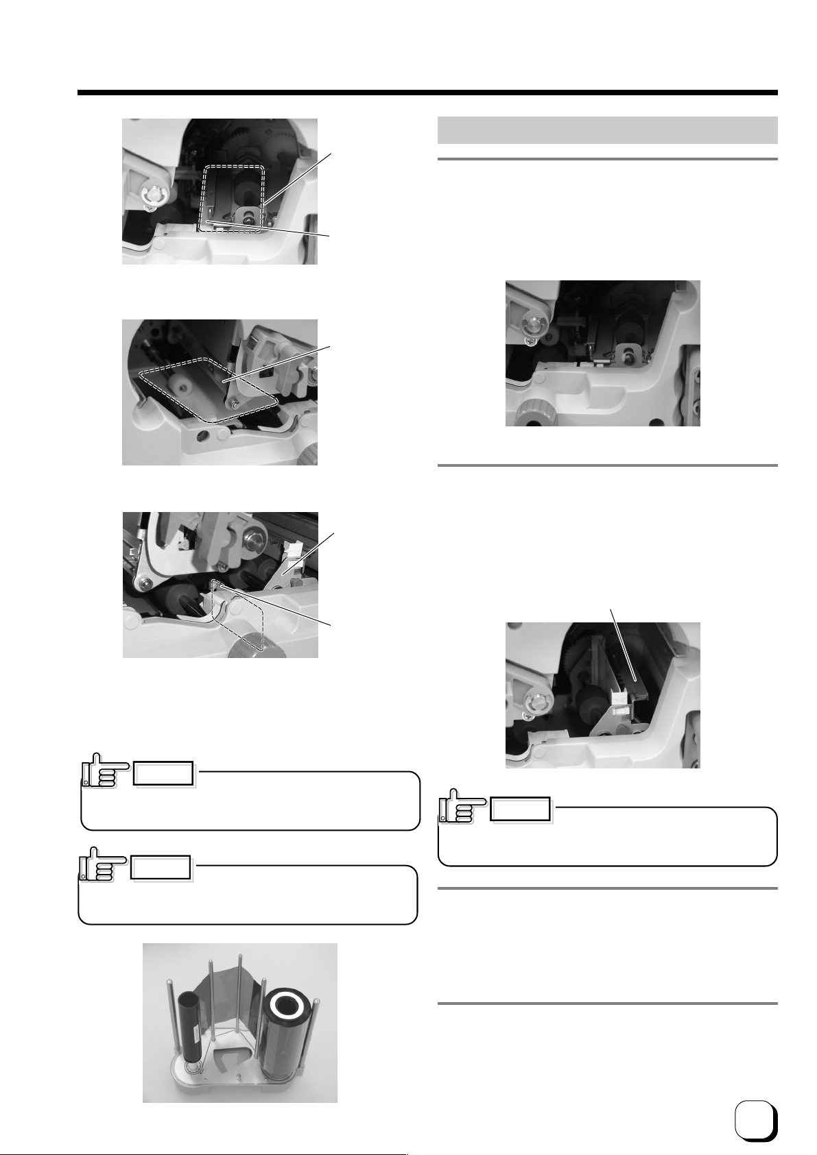
A. When card is at the right (near Turnover unit)
Thermal head
A. When card is at the right (near Turnover unit)
1. Open the jog cover behind the card cassette, and
turn the JOG dial. Refer to page 26 of this manual
(Feed Jam) on how to open the jog cover.
Push with your hand if the card does not move.
B. When card is at the left (near printing part)
Turnover
unit
Card
C. When card can barely be seen from the encoder
* The encoder (optional) is located below the turnover
unit.
CAUTION
Be careful not to drop the ink ribbon into
the interior of the printer when removing the ink cassette.
CAUTION
it. Allowing the inked surface to touch the ground will make
dirty the cassette and cause it to malfunction.
Stand the ink cassette after removing
2. With the guard component (green color) on your right,
turn the Turnover unit vertical with your hand. Turning
the Turnover unit will move the card away from its
center. As such, turn the jog dial to return card to the
center of the Turnover unit while you are turning the
Turnover unit.
Guard Component
CAUTION
careful attention to the metal edges and ensure that gloves
are used.
When turning the turnover unit, pay
3. Turn the jog dial to move card to the top and remove
with hand.
The turnover unit will return automatically to its original
position upon closing the printer door.
4. Install the ink cassette and close the printer door.
Refer to pages 12 and 13 of this manual.
Printer will start to initialize and return to the Ready mode.
27
Page 28

Troubleshooting (continued)
B. When card is at the left (near printing unit)
1. Adjust the direction of the tilted card with your hand
such that it is parallel with the card guide.
Card guide
2. Install the ink ribbon cassette and close the printer
door.
Refer to pages 12 and 13 of this manual.
Printer will start to initialize.
The card is discharged from the NG Card Outlet and
the printer is restored to the Ready mode.
3. Turn the jog dial clockwise (down) to move card from
the encoding unit to the Turnover unit, followed by
removing it with your hand. The turnover unit will
return automatically to its original position upon
closing the printer door.
4. Install the ink ribbon cassette and close the printer
door. Refer to pages 12 and 13 of this manual.
Printer will start to initialize and return to the Ready
mode.
Jam Inside Laminator
If the card is jammed between the printer and laminator,
turn both the printer knob for moving the card as well as
the jog dial of the laminator to move the card within the
printer.
Upon initializing the laminator, set the ink cassette and
close the printer door. The card will be discharged from
the NG Card Outlet. If the card is inside the laminator,
refer to the instruction manual of the laminator to remove
the jammed card.
C. When card can barely be seen from the encoding unit
1. Open the jog cover behind the card cassette, turn
the jog dial in the anti-clockwise (upward) direction
to move card into the encoder. Refer to page 26 of
this manual (Feed Jam) on how to open the jog cover.
2. If the Turnover unit is not vertical, turn it to a vertical
position with your hand.
Printer knob
28
Page 29

Procedures for Changing Thermal Head
CAUTION
Static electricity in our bodies discharged to the thermal
head may cause it to break down. Before exchange, touch
metal parts of the printer such as the screw to release the
static electricity.
Do not touch the heating unit of the thermal head with
your hand. If you have done so, follow procedures on the
page 25 of this manual to perform cleaning upon changing
the thermal head.
Carry out the work carefully and avoid knocking the
heating unit of the thermal head against any hard object.
Ensure that printer is switched off before changing.
Do not loosen or remove any screws for which instructions
are not given in the procedures.
1. Place your fingers on top of the printer door and open
by pulling it towards you.
Open slowly while supporting it with your hands.
Release
Lever
2
1
Unlock
Knob
Remove sag
CAUTION
the printer door. Do not rest your elbow or place heavy
objects on top. Doing so may damage the printer door.
Do not install the ink ribbon on top of
2. Remove ink ribbon cassette
)Hold the release lever with fingers, and
(1
lever to unlock.
* Exchanging ink ribbons:
Upon ensuring that the ink ribbon is pulled out by about 3
cm, turn the knob on the ink ribbon cassette in the direction
indicated by the arrow to tighten the ribbon sag.
Remove the ink ribbon cassette while supporting it
with both hands.
Stand the ink ribbon cassette on a flat and firm
surface.
(2)
lift the
Eject ink ribbon cassette
CAUTION
careful not to drop the ink ribbon into the interior of the printer
when removing the cassette.
When the ink ribbon is installed, be
CAUTION
When removing the cassette for
cleaning, always stand it as shown in the photo below.
Allowing the inked surface to touch the ground will dirty the
ink ribbon and cause it to malfunction.
29
Page 30
Procedures for Changing Thermal Head
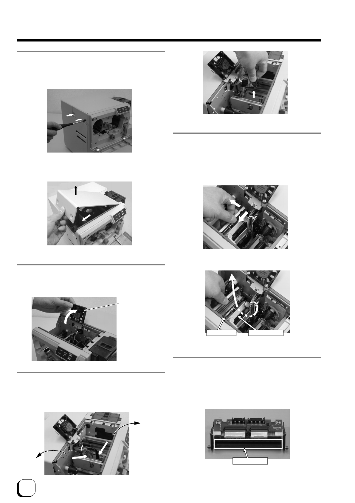
3. Open the door for head exchange
Remove the 2 fastening screws on the left of the printer’s
head exchange door using a – (flathead) driver.
6. Remove the thermal head.
To remove the thermal head from the shaft, hold and move
Slide the head exchange door to the left and remove by
lifting it up.
2
1
it to the left while pulling forward.
Lift it up while leading it through from underneath the head
bracket.
(continued)
2
1
4. Move the head cooling fan.
Lift towards you and lean it backwards.
Head cooling
fan
5. Remove head cables A and B.
Hold the part of cable that is directly above the connector
and remove by lifting them up carefully one by one.
B
(Black)
B
View from the top
Head shaft Head bracket
7. Install a new thermal head
Be careful not to hit the heating element of the thermal
head against any hard object.
Reverse steps in 6. to install the thermal head while paying
attention not to catch the head cable.
A
(Gray)
30
A
Heating Unit
Page 31

Procedures for Changing Thermal Head
Tab
Head exchange door
A
Insert the 3
alignment
tabs into the
holes on
the printer.
Press and
hold from
above and slide
it to the right.
A
(continued)
Check if the guide bearing of the thermal head is inside
the guiding slot.
Guiding Groove
Guide Bearing
Push the fastening bearing at the head fastening unit
forward and insert to the right to lock it securely.
Head fastening unit
Fastening bearing
1
Pull the fastening
bearing forward
using the head
fastening unit.
Head fastening unit
2
Push the head
fastening unit into
the back of the
fastening bearing.
Head Fastening Unit
Fastening Bearing
Hold the part that is directly above the cable connector
and insert them slowly and securely one by one.
9. Return the head cooling fan to its original position.
3
Check to ensure that the
supporter unit is properly
inserted into the hole of
the head fastening unit
and supported by the
fastening bearing.
8. Insert head cables A and B.
Press the thermal head down slowly so that the cables
can be easily inserted.
A click sound will be heard, and the ink cassette is now in
a locked state.
Supporter unit
10. Mount the head exchange door
Mount the head exchange door by reversing the steps in
3. and fasten the 2 screws securely.
CAUTION
and be careful not to distort it.
Set the head exchange door properly
31
Page 32

Procedures for Changing Thermal Head
(continued)
11. Insert the ink ribbon cassette along the guide rail.
Hold the release lever with fingers and lift it to unlock the
ink ribbon cassette.
While making sure that the ink ribbon does not sag, push
the ink ribbon cassette all the way in along the guide rail
and lower the release lever to lock the ink ribbon cassette.
Guide rail
Insert the shaft of the ink
ribbon cassette securely
into the guide rail.
CAUTION
ribbon and uneven color caused by wrinkles when the ink
ribbon cassette is attached to printer.
Ribbon sags will result in jammed ink
Checking After Changing Thermal Head
After changing the thermal head, confirm print position by
carrying out test print using color ink ribbons.
To perform a test print, press the Reset and Clean buttons
on the control panel simultaneously for more than 1 second
when the Ready LED is lit.
A test pattern will be printed. Ensure that margins around
the card are almost equal (approximately 0.2 ~ 0.3 mm)
on the top, bottom, left and right.
Top
Bottom
Left Right
Direction of test pattern: Yellow on the top left
CAUTION
is connected, do so after the laminator has switched to the
Ready mode.
To perform test print when the laminator
CAUTION
force when the shaft is not properly placed in the guide rail
may damage the device.
Inserting the ink ribbon cassette by
12. Close printer door.
Shut the printer door tightly by pressing on the top right
section of the door.
CAUTION
made in such a way that it cannot be closed properly when
the ink ribbon cassette is not locked or when the cassette is
not inserted. Closing the printer door by force in such a
case may damage the device.
To prevent damage, the printer door is
Adjust the printer setting function on the DCP360i status
monitor if the margin is not equal. Procedures for using
the DCP360i status monitor can be found in the instruction
manual (electronic manual) recorded in the attached CDROM.
The density of print may change slightly before and after
changing the thermal head. Slight adjustment of the
density can be carried out using the printer setting function
on the DCP360i status monitor.
Procedure for changing thermal head is now complete.
32
Page 33

Consumable/Optional Items/Factory default
Consult your dealer for additional purchase of consumables or optional items. If various types of cards are used
frequently, it is recommended that you purchase a card cassette according to the thickness of the cards to be used.
Consumable Items
• Cleaning Kit Order No. DIK10044
Content
Alcohol Cleaning Pad (10 pieces)
Adhesive Cleaning Card (10 pieces)
Alcohol Cotton Swab (10 pieces)
• Ink Ribbon
YMCKO 750 screen pages Order No. DIC10193
YMCKOK 600 screen pages Order No. DIC10194
K monochrome ink 2200 screen pages Order No. DIC10195
Optional Items
• Lamination Unit
Model Name
• Printer Models
EDI secure
EDI secure
• Encoder Unit
Model Name
Factory default
• YMC print level 0
• Resin K print level 0
• OP retransfer level 0
• Corecive Force Setting
Iso type Hi-Co
JIS type Lo-Co
• YMC print mode STANDARD
• Resin K print mode STANDARD
• Offset X Adjustment Value
• Offset Y Adjustment Value
• Number of write retry 2
• Unit Number 1
EDI secure
DCP360i Printer Order No. DIH10190
DCP360i Printer with MG/Chop encoder Order No. DIH10191
EDI secure
ILU Order No. DIH10173
MG/Chip encoding Module Order No. DIH10192
Microsoft®, Windows® is a registered trademark of Microsoft Corporation U.S.A. in United States of America and other
countries.
In this book, the names for Microsoft® Windows® XP operating system and Microsoft® Windows® 2000 operating
system are written as Windows® XP and Windows® 2000 respectively
33
Page 34

MEMO
34
Page 35

MEMO
35
Page 36

Software License Agreement
The software covered by this document is the computer program developed by Victor Conpany
of Japan, Limited a Japanese company, for certain card printer products (“Products”), and is
composed of the “USB Driver”, “Status Monitor” and “Printer Driver”. The foregoing software,
including the attached documentation such as its startup guide, user’s manual, etc.
(“Documentation”), is referred to as “this Software” hereafter.
The use of this Software is permitted only to you, the customer recognized as an “End User”
thereof, solely according to the terms and conditions provided in this document. This
document shall constitute a legal agreement between you and our Company (“this Agreement”)
subject to your acceptance of such terms and conditions. You, as an individual End User or
authorized representative of a corporate End User, shall implement by yourself the initial acts
such as the opening of a tangible media package, program installation, downloading, etc.
(“Initiation”) of this Software prior to the use thereof, understanding the terms and conditions in
this document.
The Initiation implemented by you is deemed as your unconditional acceptance of the terms and
conditions in this document, and this Agreement shall come into effect upon such Initiation.
You shall not use this Software if you do not accept the terms and conditions in this document.
Article 1 Ownership of Rights
The copyrights and the other intellectual property rights to this Software belong to our
Company, its affiliates or the licensor of such intellectual property rights for our Company
(“Licensor”). Our Company, its affiliates or Licensor retains all these intellectual property
rights, none of which shall be assigned or otherwise transferred to you under this
Agreement. This Software is protected by the copyrights law in Japan, other countries
and related international treaties
Article 2 Grant of License
1. You are granted a non-exclusive license (“this License”) to use this Software as integrated
with the Product in your possession, according to the restrictions and the other terms and
conditions in this Agreement. You may use this Software for your own business purposes,
implementing by yourself the Initiation of this Software on the PC you intend to use in
connection with the Product. This License shall be nontransferable except based on
Section 3 of Article 3.
- 1 -
Page 37

2. You may make the minimum number of copies necessary from this Software solely for
backup or archival purposes, besides implementing the Initiation. In all such copies, you
shall reproduce and keep the copyright notices and other legends as originally included in
the media of this Software provided by our Company.
Article 3 Restrictions on Use
1. You shall not adapt or modify this Software, nor shall you, except as permitted by applicable
law, reverse-assemble, reverse-compile, reverse-engineer or in any way try to derive from
this Software any source code.
2. You are not granted the right to distribute or sublicense this Software to any third party.
You shall not assign, lend, lease or otherwise transfer to any third party this License, this
Software or any part thereof by itself or in combination with other products or software.
3. You may transfer this Software along with this License to a third party as a new End User
only when the possession of this Software and the Product is transferred together as a set
by assignment, loan, lease, or the like. In the said case, you must present this document
to such third party and obtain its consent to this Agreement beforehand, having such third
party understand the terms and conditions herein. Our company may inquire of you to
identify such third party. Upon such transfer, you are obliged to immediately destroy or
delete this Software and all its copies, (which shall include erasing the copies stored or
recorded on your PC, other hardware, memory, etc.) except those transferred to such third
party in the tangible media like CD-ROM, printed materials, etc. (“Tangible Media”); and you
shall submit a certificate of such destruction and deletion on our Company’s request.
Article 4 Limited Warranty
1. When this Software is provided in the form of Tangible Media, our Company warrants that
such Tangible Media is free from the physical defects at the time of delivery. With respect
to the “USB Driver” and “Status Monitor” of this Software, our Company warrants that they
will materially operate in conformity to the main functional specifications expressed in the
Documentation for ninety (90) days after the delivery date of this Software, provided that the
Initiation thereof was proper and that it is operated correctly, according to the
Documentaion.
2. The limited warranty in Section 1 above is subject to the condition that the operating system
(“OS”) of the PC you intend to use in connection with this Product must be of such types
and versions as our Company stipulates in the Documentation. Our Company verifies that
this Software will function when such stipulated OS is used in combination with then major
PC models at the time of delivery, however does not warrant that it will function properly
- 2 -
Page 38

when used in combination with any and all PC models. It is recommended that you first
check the functioning of this Software in the environment where you use it, according to the
Documentation immediately after its delivery.
3. This Software is provided “As Is” with no warranties except the limited warranty expressed
in this Article. Our Company is not obliged to provide updates such as modified or
enhanced versions of this Software. No warranties whether express or implied are made
with respect to this Software in regards to its merchantability, fitness for a particular purpose,
non-infringement of third party intellectual property rights, or any other matters not expressly
provided for herein. Any problems occurring with respect to this Software shall be resolved
at your sole responsibility and expenses.
Article 5 Indemnification
Our Company shall not be liable for any damages in connection with the use of this
Software, including direct, incidental, consequential, special and punitive damages, etc.,
whether based on this Agreement or otherwise, even if our Company has been or could
have been aware of such damages. Similarly our Company shall not be liable for any
claims by any third party against you or your customers, nor shall our Company be obliged
to compensate such third party or indemnify you or your customers for such claims. You
shall indemnify and hold harmless our Company, its affiliates and Licensor worldwide from
any claim, damage, loss, expense, including attorney’s fees, or liability in connection with
your use of this Software.
Article 6 Term
1. This Agreement and this License shall come into effect when the earliest act of Initiation
implemented on your certain PC occurs. Our Company may terminate this License without
notification if you are in breach of any provision in this Agreement. Our Company further
reserves the right to claim for any damages it may suffer arising from such breach by you.
2. Upon termination of this License, you shall immediately destroy or delete this Software and
all its copies, (which shall include erasing the copies stored or recorded on your PC, other
hardware, memory, etc.) except those in the form of Tangible Media which shall be returned
to our Company, at your responsibility, and shall submit a certificate of such destruction and
deletion on our Company’s request.
Article 7 Export Control
You agree not to illegally export, re-export or otherwise ship this Software, or any part
thereof, including the information or technology, etc. embodied in this Software, to any
- 3 -
Page 39

country, territory, organization or individual, the shipping to which is prohibited or restricted
by Japan and the respective countries concerned.
Article 8 Others
1. Any modification, addition, deletion or other changes to this Agreement shall be invalid
unless such changes are made in writing and affixed with the name and seal of or signed by
the authorized representative of our Company.
2. This Agreement shall be governed by and construed in accordance with the laws of Japan.
Any disputes arising out of this Agreement shall be subject to the exclusive jurisdiction of
the Tokyo District Court as the court of first instance.
3. If any provision of this Agreement is held to be invalid according to the laws of Japan, the
remaining provisions will still remain in effect.
End of Agreement
- 4 -
Page 40

Direct Dye Sublimation Printer EDI secure DCP360i Startup Guide
Digital Identification Solutions Group of Companies
Teckstraße 52, D73734 Esslingen, Germany
Phone : +49 711 341 689 - 0
Facsimile : +49 711 341 689 - 550
®
C
2006 Digital Identifcation Solutions Group of Companies
Printed in Japan
KAT-T189-007
0606 (VP)
 Loading...