

Page 1
Copyright © 2018 by Eding CNC
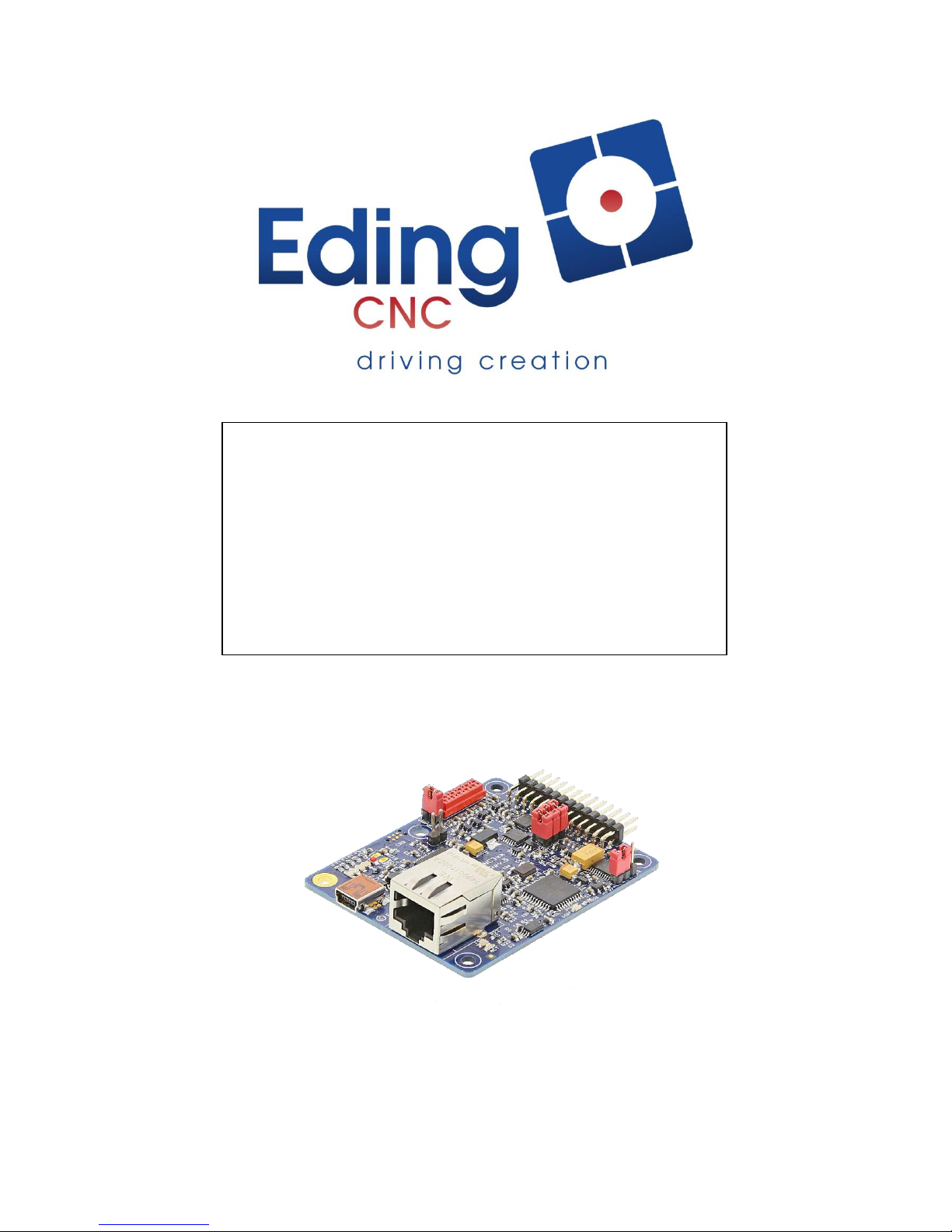
Hardware Manual
CNC310
Revision 1 30 July, 2018
Released
Page 2
Hardware Manual – CNC310
Page | 2
History:
Revision overview:
Revision
Date
Author
1
29-3-2018
AB
Revision
Remarks
1
Initial version
The information contained herein is believed to be reliable. Eding CNC makes no warranties regarding the information contain herein.
Eding CNC assumes no responsibility or liability whatsoever for any of the information contained herein. Eding CNC assumes no
responsibility or liability whatsoever for the use of the information contained herein. The information contained herein is provided "AS IS,
WHERE IS" and with all faults, and the entire risk associated with such information is entirely with the user. All information contained
herein is subject to change without notice. Customers should obtain and verify the latest relevant information before placing orders for
Eding CNC products. The information contained herein or any use of such information does not grant, explicitly or implicitly, to any party
any patent rights, licenses, or any other intellectual property rights, whether with regard to such information itself or anything described
by such information. Eding CNC products are not warranted or authorized for use as critical components in medical, life-saving, or lifesustaining applications, or other applications where a failure would reasonably be expected to cause severe personal injury or death.
Page 3

Hardware Manual – CNC310
Page | 3
Table of contents
1 Introduction .................................................................................................................................... 4
1.1 Purpose ................................................................................................................................... 4
2 Board overview ............................................................................................................................... 5
3 Board jumpers and indicators ......................................................................................................... 6
3.1 Jumper USBPWR ..................................................................................................................... 6
3.2 Jumper PRG ............................................................................................................................. 6
3.3 Jumper RDY/PLS ...................................................................................................................... 7
3.4 Jumper JP1 .............................................................................................................................. 8
3.5 Power LED ............................................................................................................................... 9
3.6 Status LED 1-4 ......................................................................................................................... 9
3.7 Network LEDs (optional) ....................................................................................................... 10
3.8 SYSRDY led ............................................................................................................................ 11
4 I/O pinning .................................................................................................................................... 12
4.1 Pinning functions overview ................................................................................................... 12
5 OUTPUTS ....................................................................................................................................... 14
5.1 TOOL output .......................................................................................................................... 14
5.2 COOLANT output ................................................................................................................... 16
5.3 STEP/DIRx output .................................................................................................................. 16
5.4 AMP-ENABLE output ............................................................................................................. 16
5.5 WATCHDOG/SYSRDY output ................................................................................................. 17
6 Inputs ............................................................................................................................................ 18
6.1 PROBE input .......................................................................................................................... 18
6.2 E-STOP input ......................................................................................................................... 19
6.3 HOME1 input ......................................................................................................................... 20
6.4 HOME4 input ......................................................................................................................... 21
7 MPG/Pendant ............................................................................................................................... 23
8 Getting started .............................................................................................................................. 24
9 Example of connecting CNC310 to Leadshine DM422C. .............................................................. 26
10 Mechanical dimensions ................................................................................................................ 27
Page 4
Hardware Manual – CNC310
Page | 4
1 Introduction
1.1 Purpose
This manual describes the hardware of the CNC310.
The CNC310 is a basic 3-axis CNC controller the specification is:
The starter software has basic operations and is able to operate 2.5D.
SW upgradable features:
- 4th Axis + home input
- Ethernet interface
- Full software support (full 3D)
3x Axis controller interface
(optional 4th axis)
Puls/Direction
5V (f
step,max
= 125Khz)
Enable
5V
1x digital HOME inputs
(optional 2nd input)
Max. 5V
1x cooling output
5V
1x toolsetter/tool length input
Max. 5V
Interface
USB
(optional Ethernet)
Power Supply
Via USB or externally 5VDC
Dimension
54.5x67.5mm
Others
- Firmware upgradable through USB connection
- Connector pitch 2.54mm/0.1”
Page 5
Hardware Manual – CNC310
Page | 5
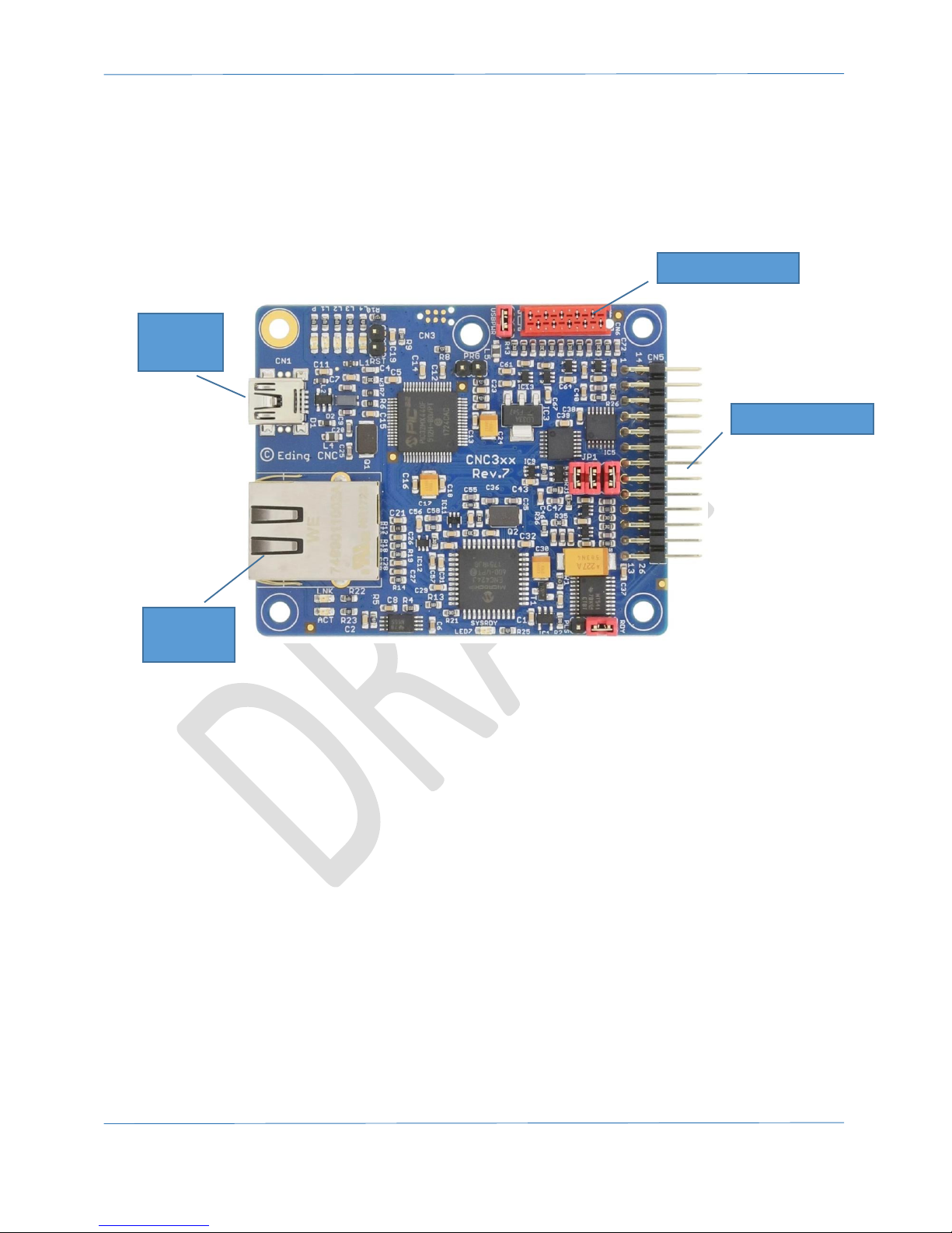
2 Board overview
The CNC310 is a CNC controller with USB interface, and is intended for 3 axes. However, the user can
upgrade the board through separate licenses with a 4th axis and activate the ethernet interface.
The image below shows an overview of the CNC310.
The purpose of the board is to offer a simple controller that can be used for operating small CNC
machines that need only limited I/O.
This document focusses on the hardware interface of this board, and how to use it to get a simple
CNC set up, up and running. This manual will only focus on the hardware part. For more information
about the software please check the software manual that can be downloaded from the website.
I/O Connector
USB
Interface
Ethernet
Interface
Wired Pendant
Page 6
Hardware Manual – CNC310
Page | 6
3 Board jumpers and indicators
This chapter describes the jumpers and indicators that are present on the controller board.
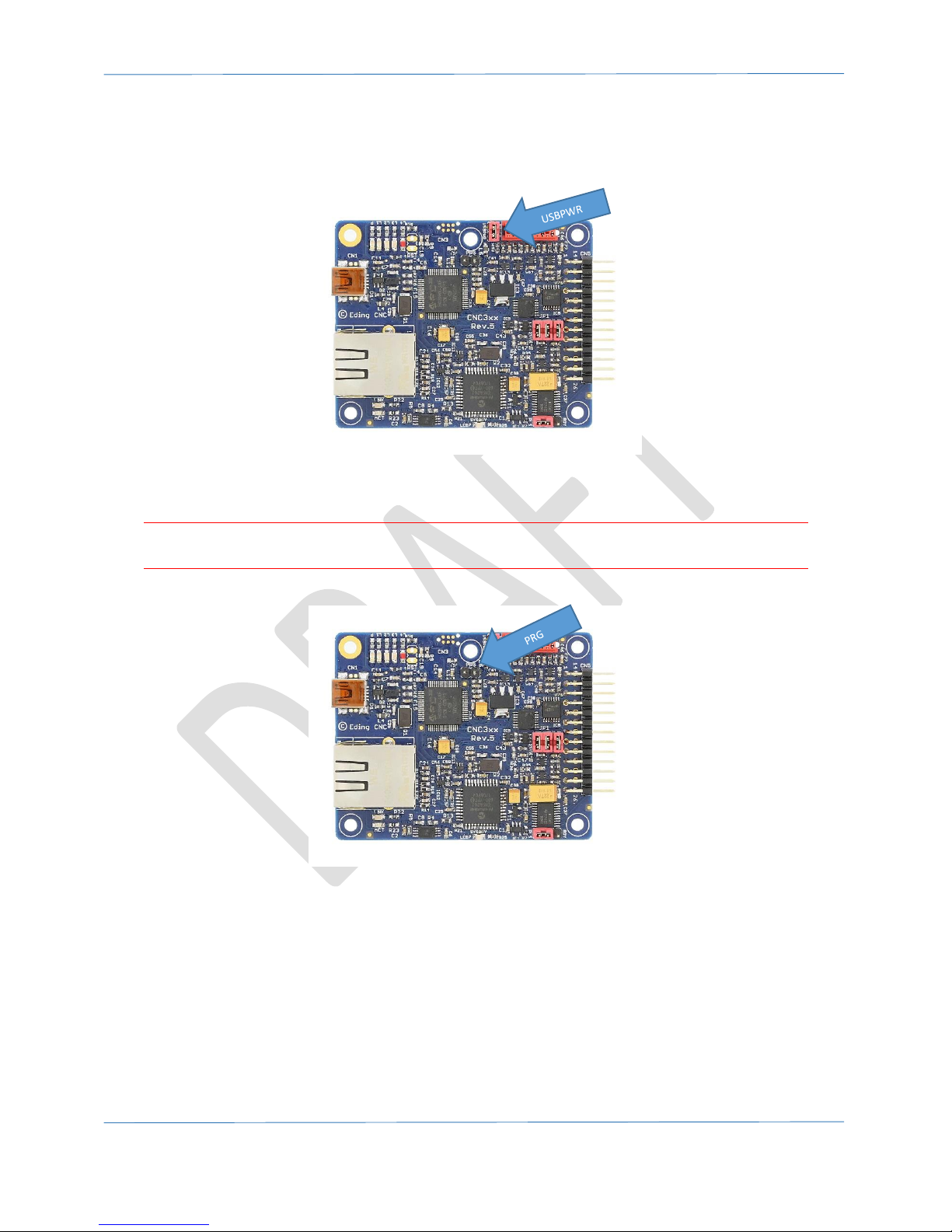
3.1 Jumper USBPWR
This jumper is used to power the board via the USB interface. The board can also be powered
through an external pin.
WARNING: If the board is powered externally make sure that the USBPWR jumper is removed
because else the USB interface will get externally powered which can damage the USB port.
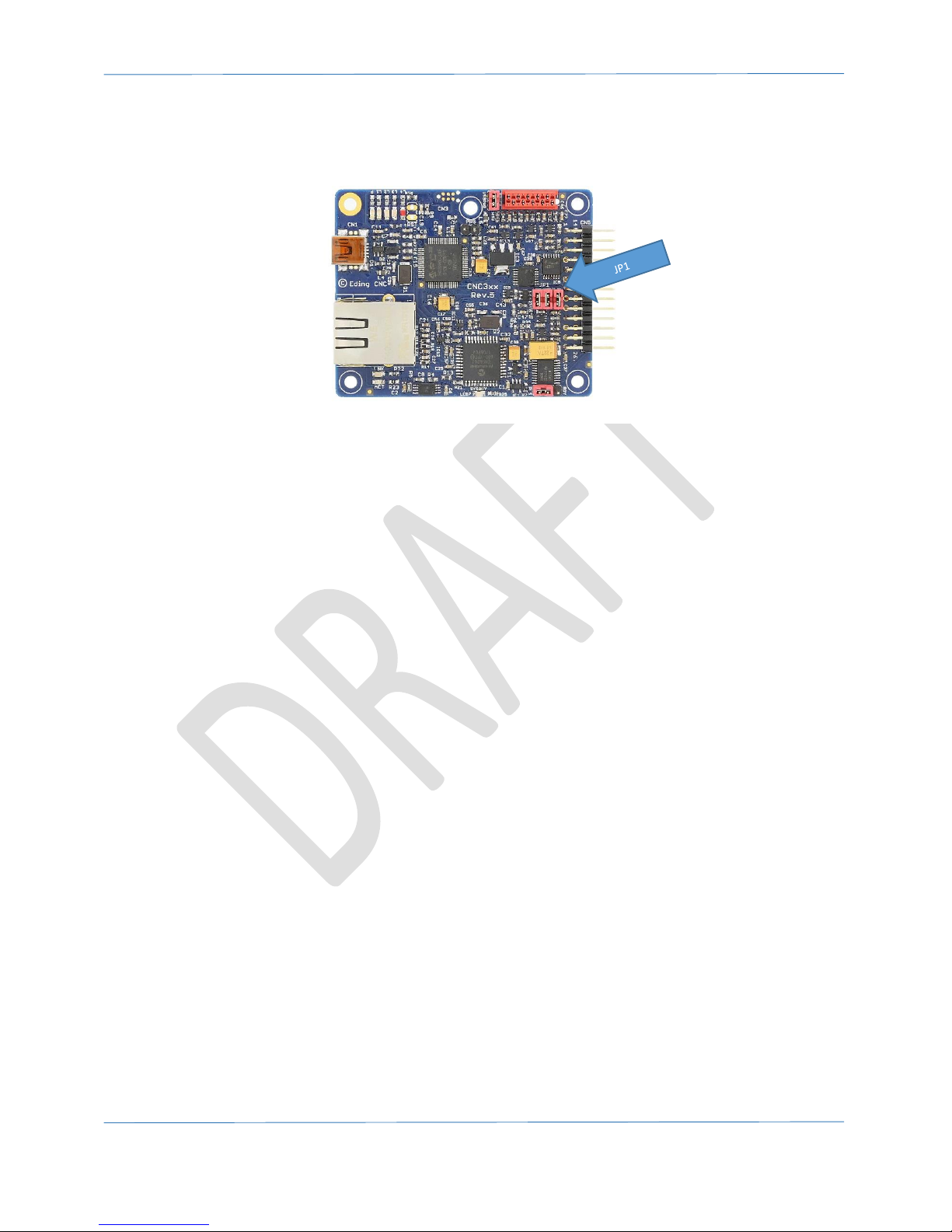
3.2 Jumper PRG
If this jumper is place the board will skip the bootloader mode and will go directly to starting the
firmware.
Page 7

Hardware Manual – CNC310
Page | 7
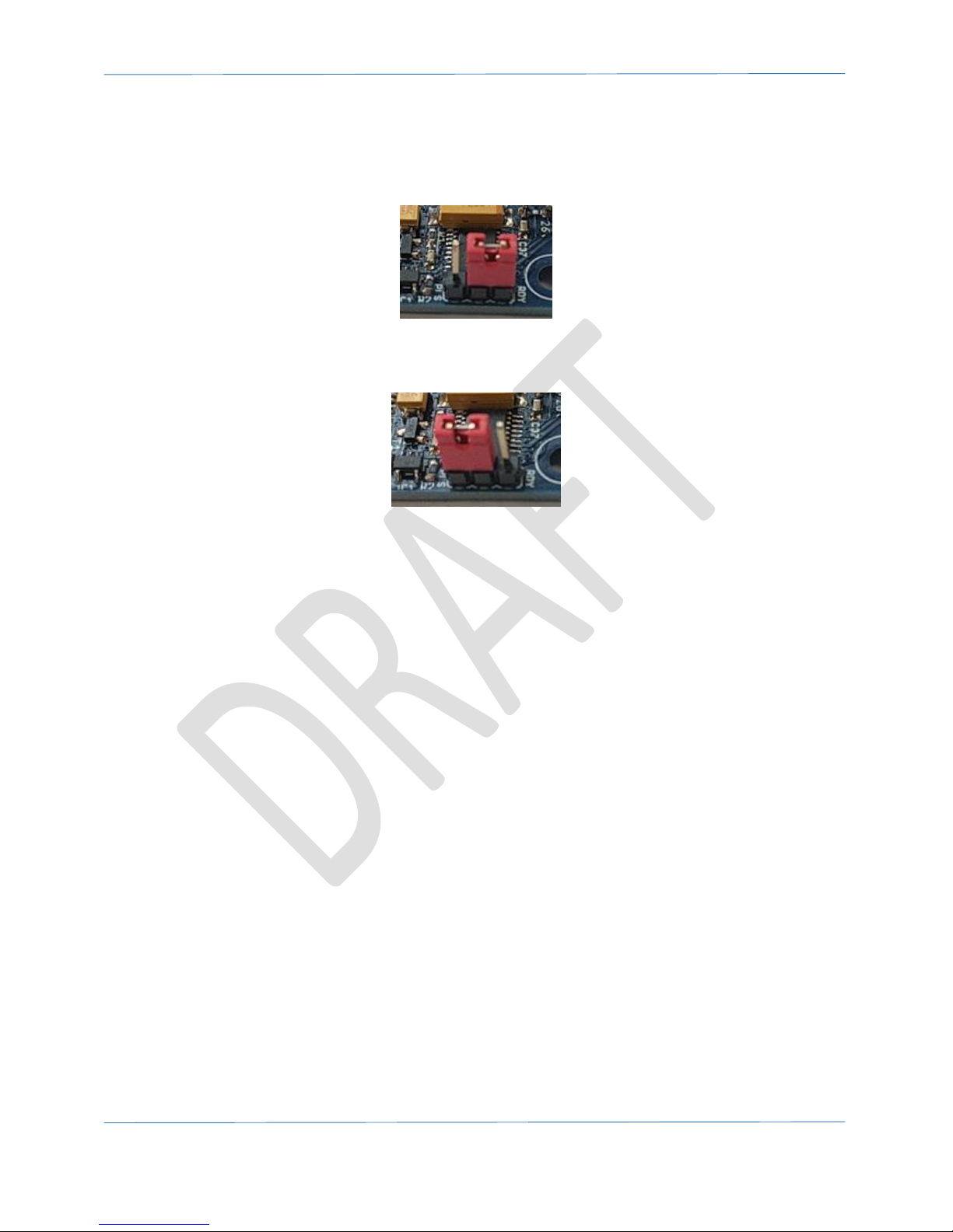
3.3 Jumper RDY/PLS
This jumper is used to set the output signal that is present on the I/O pin ‘WATCHDOG/SYSRDY‘.
For more info see chapter 5.5 WATCHDOG/SYSRDY output
Page 8
Hardware Manual – CNC310
Page | 8
WATCHDOG/SYSRDY output.
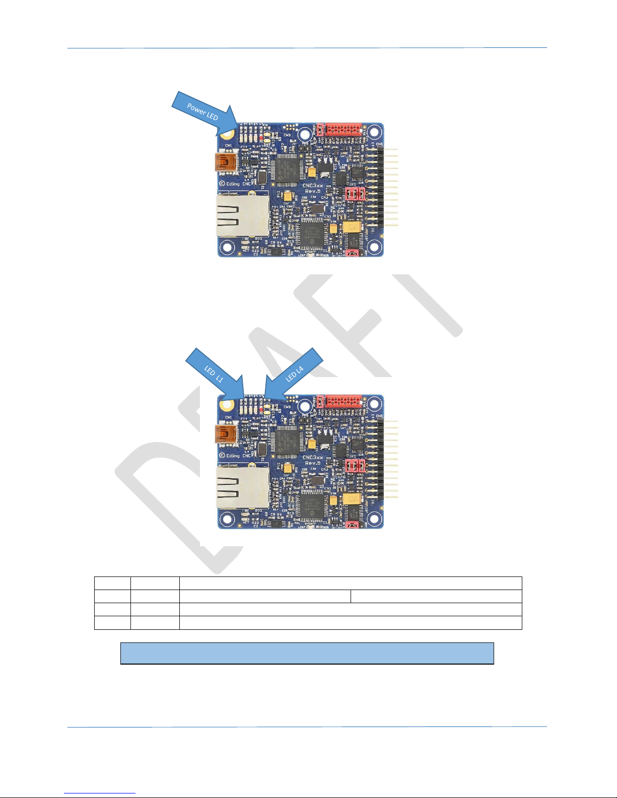
3.4 Jumper JP1
This jumper can be used to deactivate the signals on some I/O pins. Currently make sure that all
jumpers are mounted.
Page 9
Hardware Manual – CNC310
Page | 9
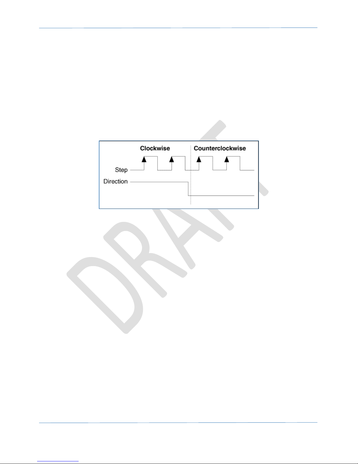
3.5 Power LED
This blue power led indicates when power is applied to the board.
3.6 Status LED 1-4
The status LEDs indicate the current mode of the controller. The status LEDs are indicated by L1
through L4.
L1
ORANGE
BLINKING = Board is starting
L2
GREEN
ON = System is active
OFF = System if inactive
L3
GREEN
BLINKING = Board is active
L4
RED
BLINKING = Watchdog is active
Please note,
when in bootloader mode L2 and L3 will toggle to indicate this.
Page 10

Hardware Manual – CNC310
Page | 10
3.7 Network LEDs (optional)
The network LEDs will only be active if the license has been activated for the network and new
firmware has been downloaded.
The LINK LED indicates if a network cable is connected. The ACTIVITY LED will blink if there is
network communication.
Page 11

Hardware Manual – CNC310
Page | 11
3.8 SYSRDY led
The LED indicates that status of the SYSRDY output. If it is ON, it indicates that the signal on the
WATCHDOG/SYSRDY output also is active.
Page 12

Hardware Manual – CNC310
Page | 12
4 I/O pinning
4.1 Pinning functions overview
The board can be connected through a 26-pole header. The pitch of the connector is 2.54mm or
0.1”. The images below show the pin numbering and the functions on each pin.
Figure 1. Pin numbering on connector.
Figure 2. Functions on connector overview.
Page 13

Hardware Manual – CNC310
Page | 13
In “Figure 3. Overview of functions.” all signals that are present are discussed in more detail.
Make sure that the maximum in or output limitations are not exceeded.
Figure 3. Overview of functions.
Pin
#
Name
Direction
Type
Function
Electrical Spec.
Remarks
1
TOOL
OUT
DIGITAL
Switching of tool
TTL 5V/20mA
2
DIR1
OUT
DIGITAL
Direction signal X axis
TTL 5V/20mA
3
STEP1
OUT
DIGITAL
Step signal X axis
TTL 5V/20mA
Max. 125kHz
4
DIR2
OUT
DIGITAL
Direction signal Y axis
TTL 5V/20mA
5
STEP2
OUT
DIGITAL
Step signal Y axis
TTL 5V/20mA
Max. 125kHz
6
DIR3
OUT
DIGITAL
Direction signal Z axis
TTL 5V/20mA
7 STEP3
OUT
DIGITAL
Step signal Z axis
TTL 5V/20mA
Max. 125kHz
8
DIR4*1
OUT
DIGITAL
Optional: Direction signal A axis
TTL 5V/20mA
9 STEP4*1
OUT
DIGITAL
Optional: Step signal A axis
TTL 5V/20mA
Max. 125kHz
10
PROBE
IN
DIGITAL
Probe input
Max. 5V
11
E-STOP
IN
DIGITAL
Emergency stop signal input
Max. 5V
12
HOME1
IN
DIGITAL
Input for homing switches
Max. 5V
13
HOME4*1
IN
DIGITAL
Optional: input home switch A axis
Max. 5V
14
reserved
Do not connect
15
reserved
Do not connect
16
COOLANT
OUT
DIGITAL
Controlling the coolant.
TTL 5V/20mA
17
reserved
Do not connect
18
GND
GROUND
19
reserved
Do not connect
20
reserved
Do not connect
21
reserved
Do not connect
22
WATCHDOG/SYSRDY
OUT
DIGITAL
Indication if system is active
TTL 5V/20mA
23
AMP-ENABLE
OUT
DIGITAL
Enabling motor drivers
TTL 5V/150mA
24
GND
GROUND
25
GND
GROUND
26
+5V*2
IN/OUT
POWER
Power supply, can be in and output.
Max. 5V
Page 14

Hardware Manual – CNC310
Page | 14
5 OUTPUTS
5.1 TOOL output
The TOOL output is used for switching ON and OFF the tool of your machine. The TOOL output is not
cable of switching large loads. Therefor it will need a relay to switch large loads.
Standard relays cause a lot of EMI noise. EMI noise can disturb the USB communication.
We therefor recommend using a solid-state relay.
Figure 4. Example of solid-state relay.
A solid-state relay can be often connected directly to the TOOL output. Please check the current that
the solid-state relay input needs do not exceed the maximum current that the port can supply.
The biggest difference between a ‘normal’ relay and a solid-state relay is that the lather does not
have moving parts and in and output are also separated through a optocoupler. It should cause
much less EMI problems.
Connecting a solid-state relay is shown in the image below:
Figure 5. Connecting a solid-state relay.
TOOL output
Page 15

Hardware Manual – CNC310
Page | 15
If you want to use a ‘normal’ relay it’s important to check the current that a relay needs to switch.
This can be improved by adding a transistor to the output of the board as shown in the image below.
Figure 6. How to switch a power relay.
This image shows how you can control a 5V or 24V (or almost any) relay with the output of the
CNC310. It might be easier to find a board that has all logic already included on one board, and
which can readily be found in the internet. Some will even include optocouplers.
Figure 7. Example of finished relay interface.
We recommended to use standard relays only for low power.
However, our advices remains to use solid state relay.
Please note to always use an anti-parallel diode of 100-200v / 1-2 Amp. Without this
diode the controller may be damaged.
Page 16
Hardware Manual – CNC310
Page | 16
5.2 COOLANT output
The coolant output can be used to control any form of coolant that might be used during the
operation of the machine. Its output is electrically identical to the TOOL output. For information
about how to use this please refer to that part of the document.
5.3 STEP/DIRx output
The controller board features 3, optional 4, outputs for controlling the driver of a stepper motor. The
signals generated are the common signals STEP and DIRECTION, as used by many drivers.
The DIRECTION signal indicates to the driver whether it has the move clockwise (CW) of counterclockwise (CCW). The STEP signal indicates when a step is to be made. Figure 8 illustrates this.
Figure 8. Example of STEP/DIRECTION signal.
Whether the DIRECTION signal means CW or CCW depends on the stepper driver and how you wire
it or configure it. Also, whether the low/high or high/low signal indicates a step depends on the way
it is connected and used by the driver.
Please refer to you motor driver’s manual to find more information about how to connect the
controller to it.
5.4 AMP-ENABLE output
The AMP-ENABLE output is used for enabling the motor drivers. This output can supply more output
current than the other digital outputs.
See also chapter 9 Example of connecting CNC310 to Leadshine DM422C.
Page 17
Hardware Manual – CNC310
Page | 17
5.5 WATCHDOG/SYSRDY output
The WATCHDOG/SYSRDY can be used to indicate when the system is active. This can be either with a
HIGH (active) / LOW (not active) signal or by outputting a square wave of 12 kHz. Often that signal is
used as a kind of watchdog signal by for example stepper drivers.
Figure 9. Output is HIGH if SYSREADY is active
Figure 10. Output is square wave if SYSREADY is active.
This HIGH/LOW signal is selected by setting the jumper on the ‘RDY’ position, the square wave is
selected by selecting the ‘PLS’ position.
Page 18
Hardware Manual – CNC310
Page | 18
6 Inputs
This chapter describes how to use the inputs of the controller board. Make sure that the input
signals do not exceed the maximum values of the input.
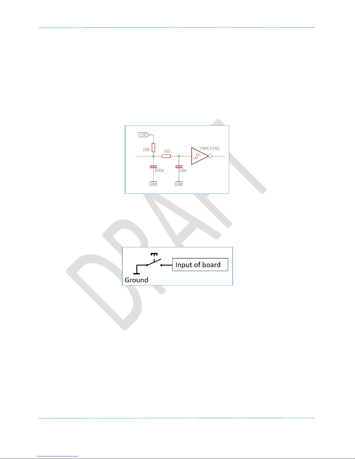
6.1 PROBE input
The PROBE input has multiple functions, it can be used for:
- Determining the height of the material
- Determining the length of a tool
The figure below, it shows how the input circuit is designed.
Figure 11. Probe input circuit.
This image shows that on the input a 10k resistor is used as a pull-up. This means that IF you would
measure on this input you will measure 5V. Please note, that this is not the ‘real’ 5V but just a pullupped value. The image also shows, in order to activate this input you need to connect it to ground.
In the image below this is illustrated.
Figure 12. Connecting switch to probe input.
Page 19
Hardware Manual – CNC310
Page | 19
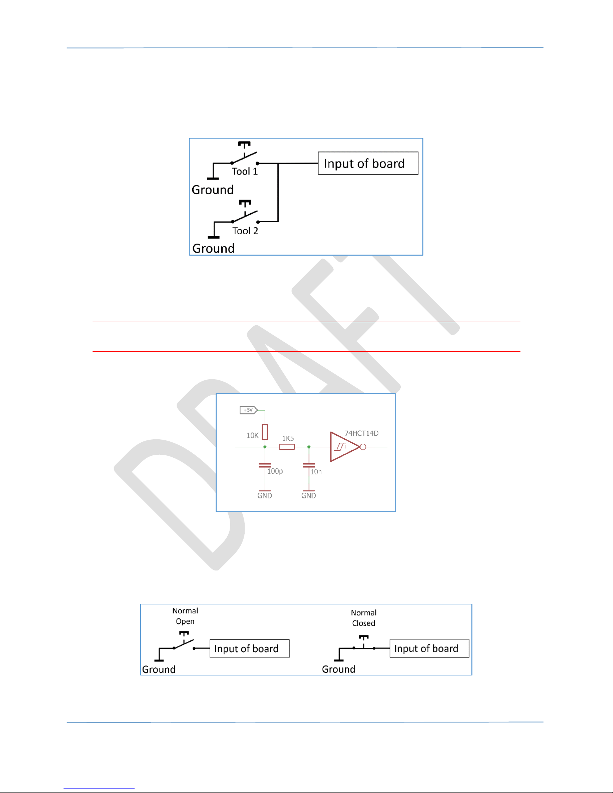
If you need to connect multiple devices to this input, you can simply connect them in parallel, as
shown in the image below. The system will know when to consider this an actual probe or when it is
a toolsetter.
Figure 13. Connecting multiple tools to probe input.
6.2 E-STOP input
The E-STOP input signals that the systems needs to stop immediately.
Warning: The E-STOP does not replace a proper external E-STOP switch, the user is responsible for
having an external hardware E-STOP switch to switch off the machine in case of emergency.
The figure below shows how the input circuit is designed.
Figure 14.E-STOP input circuit.
This image shows that on the input a 10k resistor is used as a pull-up. This means that IF you would
measure on this input you will measure 5V. Please note, that this is not the ‘real’ 5V but just a pull-
upped value. The image also shows that in order to activate this input you need to connect it to
ground. In the image below this is illustrated for a Normal-Open and Normal-Closed switch.
Figure 15. Connecting switch to E-STOP input.
Page 20
Hardware Manual – CNC310
Page | 20
In the software it must be indicated whether a switch is either Normal-Open (NO) or Normal-Closed
(NC). This is set via ‘Homing and E-Stop’ part of the setup screen. A message will appear onscreen to
show that an E-STOP condition has occurred.
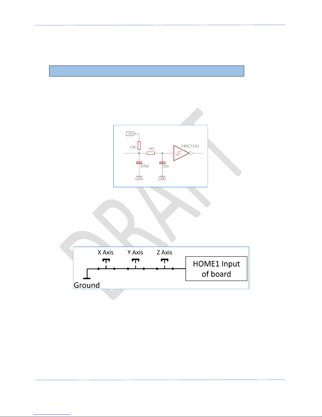
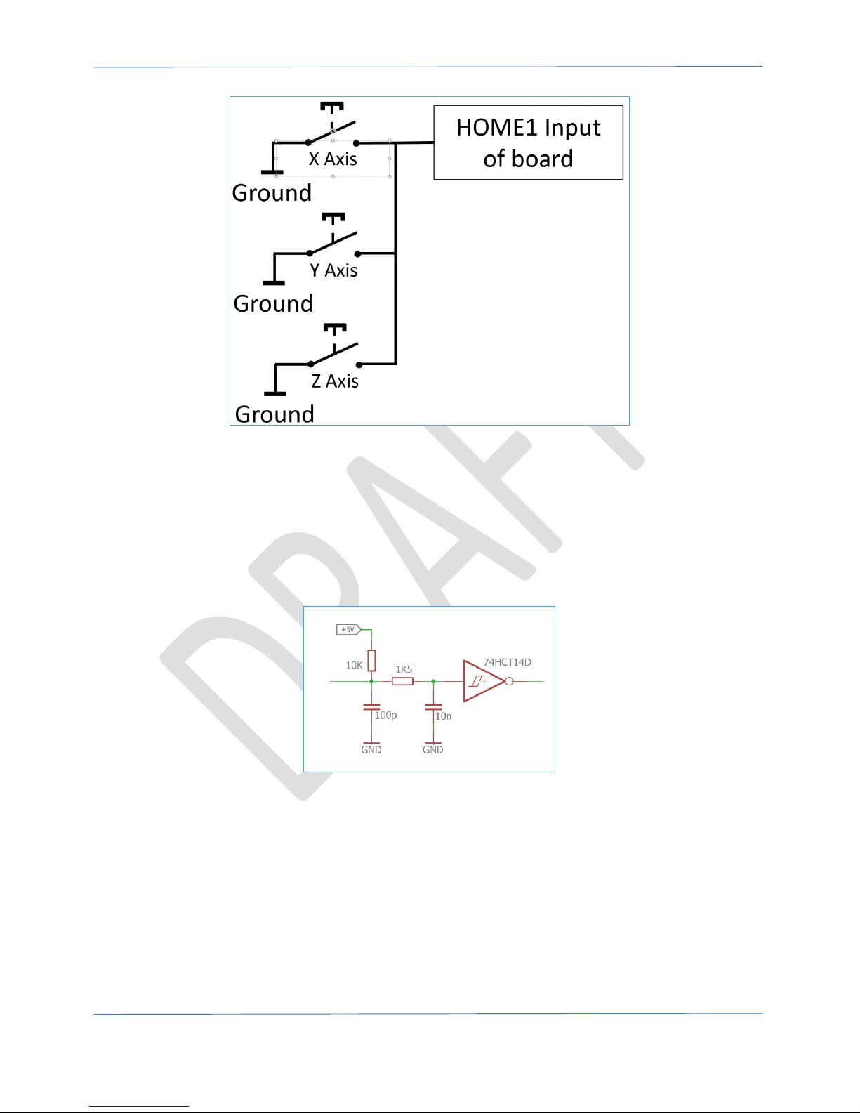
6.3 HOME1 input
The HOME1 input is used for connecting the X, Y and Z home switches for the machine so it knows
where it is.
The figure below shows how the input circuit is designed.
Figure 16. Home1 input circuit.
This image shows that on the input a 10k resistor is used as a pull-up. This means that IF you would
measure on this input you will measure 5V. Please note, that this is not the ‘real’ 5V but just a pull-
upped value. This input is used for the X, Y and Z axis. Depending on the type of switch, Normal
Open or Normal Closed, the switched need to be connected differently.
Figure 17. Connecting Normal-Closed home switches in series.
Please note, by default the E-STOP input is disabled.
Page 21
Hardware Manual – CNC310
Page | 21
Figure 18. Connecting Normal-Open home switches in parallel.
In the software it must be indicated whether a switch is either Normal-Open (NO) or Normal-Closed
(NC). This is set via ‘Homing and E-Stop’ part of the setup screen.
6.4 HOME4 input
The HOME4 input is used if a 4th axis is activated. This input takes only a single home switch.
The figure below it shows how the input circuit is designed.
Figure 19. Home1 input circuit.
This image shows that on the input a 10k resistor is used as a pull-up. This means that IF you would
measure on this input you will measure 5V. Please note, that this is not the ‘real’ 5V but just a pullupped value.
Page 22

Hardware Manual – CNC310
Page | 22
Please note, that all home switches need to be the same with respect to Normal-Open or NormalClose.
Figure 20. Connecting switch to HOME4 input.
In the software it must be indicated whether a switch is either Normal-Open (NO) or Normal-Closed
(NC). This is set via ‘Homing and E-Stop’ part of the setup screen.
Page 23

Hardware Manual – CNC310
Page | 23
7 MPG/Pendant
The MPG connectors makes it possible to directly connect a pendant to the controller.
This option is only available if the full software is used.
<TO BE ADDED>
Page 24
Hardware Manual – CNC310
Page | 24
8 Getting started
Before installing the board it’s a good idea to validate that the board is operational.
A. Validate the board is active
Step 1. The first step is to validate the board is operational. Connect the USB.
Step 2. As a result the blue power led should turn on. Also, observe that the status LEDs indicates
that the board is active, indicated by the ‘heart beat’. See also “3.6 Status LED 1-4”.
Step 3. The board is now able to communicate with the application software. If you startup the
software the board should be found. This is indicated by the controller type ‘CNC310’ appearing in
the top-left of the window. If the board is not found it will show ‘SIMULATION’.
B. Check for motion
Now the board is operational the next step is to check whether the machine and home switches
work correctly. We start with the homing switches. Make sure that the power is off.
Step 1. Connect the home-switches
Step 2. Power up the board and connect with it with the software.
Step 3. By using the I/O screen of the application validate that the switches are correctly detected;
make sure not to forget to setup the switches in the setup screen of the software. This is
determined by the HomeInputSenseLevel, at default it is Normal Open.
Step 4. First, check there is no power connected. Next, connect the driver(s) to the board, you can
choose to connect all motors at once or just one at a time. Please check the manual of the
driver on how to connect it to the controllers, also check that the enable is correctly
connected. Some drivers will automatically be enabled when this input is not connected, and
they are powered up.
Step 5. DOUBLE check all connections.
Step 6. Power up the board and driver(s) and re-connect with it.
Step 7. Normally with the default settings of the software you should be able to get some motion. If
not please check the following:
- Are all signals correctly connected?
- Do some signals need to be inverted (e.g. enable)?
Page 25

Hardware Manual – CNC310
Page | 25
TIP: By using the software I/O screen you can manually control enabling the drivers. When the drive
is not enabled you will be able to move the axis by hand, if it is enabled this should not be possible.
If all checks went ok, your machine has now a basic setup. From here you can continue to connect
more I/O (eg. E-STOP) to the board, please check all I/O via the software; also check whether
inversion is necessary.
Please note that the system will need to be tuned to each specific machine. This means that machine
parameters as speed/acceleration etc. will need to be changed to get optimum performance. Please
make sure you know how to do this, and if not request support.
Page 26

Hardware Manual – CNC310
Page | 26
9 Example of connecting CNC310 to Leadshine DM422C.
In the image below is drawing of how to simple the CN310 can be connected to a DM422C.
Figure 21. Connecting CNC310 to Leadshine DM422C.
Page 27

Hardware Manual – CNC310
Page | 27
10 Mechanical dimensions
The controller can simply be connected by using standard connector (2x13 pole), pitch 2.54mm/0.1”:
For example:
Wurth WR-PHD 613026243121
 Loading...