

Page 1

AC1200 Wireless LAN
Concurrent Dual Band
Gigabit Router
(2.4GHz: 300Mbps, 5GHz: 867Mbps)
User’s Manual
Version: 1.0
(January, 2013)
1
Page 2

COPYRIGHT
Copyright ©2013 by this company. All rights reserved. No part of this publication
may be reproduced, transmitted, transcribed, stored in a retrieval system, or translated
into any language or computer language, in any form or by any means, electronic,
mechanical, magnetic, optical, chemical, manual or otherwise, without the prior
written permission of this company
This company makes no representations or warranties, either expressed or implied,
with respect to the contents hereof and specifically disclaims any warranties,
merchantability or fitness for any particular purpose. Any software described in this
manual is sold or licensed "as is". Should the programs prove defective following
their purchase, the buyer (and not this company, its distributor, or its dealer) assumes
the entire cost of all necessary servicing, repair, and any incidental or consequential
damages resulting from any defect in the software. Further, this company reserves the
right to revise this publication and to make changes from time to time in the contents
thereof without obligation to notify any person of such revision or changes.
2
Page 3

Federal Communication Commission
Interference Statement
FCC Part 15
This device complies with part 15 of the FCC Rules. Operation is subject to the
following two conditions: (1) This device may not cause harmful interference, and (2)
this device must accept any interference received, including interference that may
cause undesired operation.
This equipment has been tested and found to comply with the limits for a Class B
digital device, pursuant to Part 15 of FCC Rules. These limits are designed to provide
reasonable protection against harmful interference in a residential installation. This
equipment generates, uses, and can radiate radio frequency energy and, if not installed
and used in accordance with the instructions, may cause harmful interference to radio
communications. However, there is no guarantee that interference will not occur in a
particular installation. If this equipment does cause harmful interference to radio or
television reception, which can be determined by turning the equipment off and on,
the user is encouraged to try to correct the interference by one or more of the
following measures:
1. Reorient or relocate the receiving antenna.
2. Increase the separation between the equipment and receiver.
3. Connect the equipment into an outlet on a circuit different from that to
which the receiver is connected.
4. Consult the dealer or an experienced radio technician for help.
Changes or modifications not expressly approved by the party responsible for
compliance could void the user‘s authority to operate the equipment.
Operations in the 5.15-5.25 GHz band are restricted to indoor usage only.
3
Page 4

FCC Caution
This equipment must be installed and operated in accordance with provided
instructions and a minimum 20 cm spacing must be provided between computer
mounted antenna and person’s body (excluding extremities of hands, wrist and feet)
during wireless modes of operation.
This device complies with Part 15 of the FCC Rules. Operation is subject to the
following two conditions: (1) this device may not cause harmful interference, and (2)
this device must accept any interference received, including interference that may
cause undesired operation.
Any changes or modifications not expressly approved by the party responsible for
compliance could void the authority to operate equipment.
This device is restricted to indoor use when operated in the 5.15 to 5.25 GHz
frequency range.
Federal Communication Commission (FCC) Radiation Expos ure
Statement
This equipment complies with FCC radiation exposure set forth for an uncontrolled
environment. In order to avoid the possibility of exceeding the FCC radio frequency
exposure limits, human proximity to the antenna shall not be less than 20cm (8 inches)
during normal operation.
The antenna(s) used for this transmitter must not be co-located or operating in
conjunction with any other antenna or transmitter.
The equipment version marketed in US is restricted to usage of the channels 1-11
only.
4
Page 5

R&TTE Compliance Statement
This equipment complies with all the requirements of DIRECTIVE 1999/5/EC OF
THE EUROPEAN PARLIAMENT AND THE COUNCIL of March 9, 1999 on radio
equipment and telecommunication terminal Equipment and the mutual recognition of
their conformity (R&TTE).
The R&TTE Directive repeals and replaces in the directive 98/13/EEC
(Telecommunications Terminal Equipment and Satellite Earth Station Equipment) As
of April 8, 2000.
Safety
This equipment is designed with the utmost care for the safety of those who install
and use it. However, special attention must be paid to the dangers of electric shock
and static electricity when working with electrical equipment. All guidelines of this
and of the computer manufacture must therefore be allowed at all times to ensure the
safe use of the equipment.
EU Countries Intended for Use
The ETSI version of this device is intended for home and office use in Austria,
Belgium, Denmark, Finland, France, Germany, Greece, Ireland, Italy, Luxembourg,
the Netherlands, Portugal, Spain, Sweden, and the United Kingdom.
The ETSI version of this device is also authorized for use in EFTA member states:
Iceland, Liechtenstein, Norway, and Switzerland.
EU Countries Not intended for use
None.
5
Page 6

CATALOG
Chapter I: Product Information 1-1 Introduction and safety information ..................... 9
1-2 Safety Information ......................................................................................... 11
1-3 System Requirements .................................................................................... 13
1-4 Package Contents ........................................................................................... 14
1-5 Familiar with your new wireless broadband router ....................................... 15
Chapter II: System and Network Setup ........................................................................ 18
2-1 Build network connection .............................................................................. 18
2-2 Connecting to wireless broadband router by web browser............................ 20
2-2-1 Windows 95/98/Me IP address setup: ................................................ 20
2-2-2 Windows 2000 IP address setup: ........................................................ 22
2-2-3 Windows XP IP address setup: ........................................................... 24
2-2-4 Windows Vista/Windows 7 IP address setup: ..................................... 26
2-2-5 Windows 8 IP address setup: .............................................................. 28
2-2-6 Router IP address lookup ................................................................... 30
2-3 Using ‘Quick Setup’ ...................................................................................... 34
2-3-1 Setup procedure for ‘Cable Modem’: ................................................. 36
2-3-2 Setup procedure for ‘Fixed-IP xDSL’: ............................................... 37
2-3-3 Setup procedure for ‘PPPoE xDSL’: .................................................. 38
2-3-4 Setup procedure for ‘PPTP xDSL’: .................................................... 40
2-3-5 Setup procedure for ‘L2TP xDSL’: ..................................................... 42
2-3-6 Setup procedure for ‘Telstra Big Pond’: ............................................ 44
2-4 Basic Setup .................................................................................................... 46
2-4-1 Time zone and time auto-synchronization ......................................... 47
2-4-2 Change management password .......................................................... 48
2-4-3 Remote Management.......................................................................... 50
2-5 Setup Internet Connection (WAN Setup) ...................................................... 52
2-5-1 Setup procedure for ‘Dynamic IP’: .................................................... 53
2-5-2 Setup procedure for ‘Static IP’: ......................................................... 54
2-5-3 Setup procedure for ‘PPPoE’: ........................................................... 55
2-5-4 Setup procedure for ‘PPTP’: .............................................................. 57
2-5-5 Setup procedure for ‘L2TP’: .............................................................. 59
2-5-6 Setup procedure for ‘Telstra Big Pond’: ............................................ 61
2-5-7 Setup procedure for ‘DNS’: ................................................................ 62
2-5-8 Setup procedure for ‘DDNS’: ............................................................. 64
2-5-9 Setup procedure for ‘WISP’: .............................................................. 66
2-6 Wired LAN Configurations ........................................................................... 69
6
Page 7

2-6-1 LAN IP section: .................................................................................. 70
2-6-2 DHCP Server: .................................................................................... 71
2-6-3 Static DHCP Leases Table: ................................................................ 72
2-7 Wireless LAN Configurations ....................................................................... 74
2-7-1 Basic Wireless Settings ...................................................................... 75
2-7-1-1 Setup procedure for ‘Access Point’: ...................................... 77
2-7-1-2 Setup procedure for ‘Station-Infrastructure’: ...................... 81
2-7-1-3 Setup procedure for ‘AP Bridge-Point to Point’: .................. 83
2-7-1-4 Setup procedure for ‘AP Bridge-Point to Multi-Point’: ....... 84
2-7-1-5 Setup procedure for ‘AP Bridge – WDS’............................... 86
2-7-1-6 Setup procedure for ‘Universal Repeater’ ............................ 88
2-7-2 Advanced Wireless Settings ............................................................... 90
2-7-3 Wireless Security ................................................................................ 93
2-7-3-1 Disable wireless security ....................................................... 94
2-7-3-2 WEP - Wired Equivalent Privacy ........................................ 94
2-7-3-3 Wi-Fi Protected Access (WPA): ............................................. 97
2-7-3-4 WP A RADIUS: ....................................................................... 98
2-7-4 Wireless Access Control ................................................................... 100
2-7-5 Wi-Fi Protected Setup (WPS) .......................................................... 103
2-7-6 Security Tips for Wireless Network ................................................. 106
Chapter III Advanced Functions ................................................................................ 107
3-1 Quality of Service (QoS) ............................................................................. 107
3-1-1 Basic QoS Settings ........................................................................... 107
3-1-2 Add a new QoS rule ......................................................................... 110
3-2 Network Address Translation (NAT) ........................................................... 113
3-2-1 Basic NAT Settings (Enable or disable NAT function) .................... 113
3-2-2 Port Forwarding................................................................................ 114
3-2-3 V irtual Server ................................................................................... 116
3-2-4 Port Mapping for Special Applications ............................................ 119
3-2-5 UPnP Setting .................................................................................... 121
3-2-6 ALG Settings .................................................................................... 122
3-3 Firewall ........................................................................................................ 124
3-3-1 Access Control.................................................................................. 125
3-3-2 URL Blocking .................................................................................. 129
3-3-3 DoS Attack Prevention ..................................................................... 131
3-3-3-1 DoS - Advanced Settings ...................................................... 134
3-3-4 Demilitarized Zone (DMZ) .............................................................. 135
3-4 System Status ............................................................................................... 138
7
Page 8

3-4-1 System information and firmware version ....................................... 139
3-4-2 Internet Connection Status ............................................................... 139
3-4-3 Device Status .................................................................................... 140
3-4-4 System Log ....................................................................................... 141
3-4-5 Security Log ..................................................................................... 142
3-4-6 Active DHCP client list .................................................................... 144
3-4-7 Statistics ........................................................................................... 145
3-5 System T ools ................................................................................................ 146
3-5-1 Configuration Backup and Restore .................................................. 147
3-5-2 Firmware Upgrade............................................................................ 148
3-5-3 System Reset .................................................................................... 149
Chapter IV: Appendix................................................................................................. 150
4-1 Hardware Specification ............................................................................... 150
4-2 Troubleshooting ........................................................................................... 151
4-3 Glossary ....................................................................................................... 154
8
Page 9

Chapter I: Product Information
1-1 Introduction and safety information
Thank you fo r purchasing this wireless concurrent dual band router! This
cost-effective router is the best choice for Small office / Ho me office
users, all computers and network devices can share a single xDSL / cable
modem internet connection at high speed. Easy install procedures allows
any computer users to setup a network environment in very short time within minutes, even inexpe rienced. When the number of your computers
and network-enabled devices grow, you can also expand the number of
network slo t by simple atta ch a hub or switc h, to extend the s cope of your
network!
With built-in both 2.4GHz and 5GHz radios, this router suppor ts both of
the IEEE 802.11b/g/n and 802.11a/n/ac wireless network ca pab i lit ies
simultaneously, all computers and wirele ss-enabled networ k dev ice s
(including PDA, Smart phone, Game console, Tablet and more!) can
connect to this wireless router without ad ditional cabling. New 11ac
wireless capability also gives you the highest speed of wireless
experience ever! With a compatible wireless card installed in your PC,
you can tran sfer file for up to 300Mbps+867Mbps (transfer data rate)!
The radio coverage is also doubled, so don’t worry if your office or house
is really big!
Other features of this router includi n g:
• Supports 2.4GHz and 5GHz wireless devices simultaneously.
• High wireless access throughput, up to 300Mbps+867Mbps (transfer
data rate)!
• Allow multiple users to share a single Internet line.
• Share a single Cable or xDSL internet connection.
• Access private LAN servers from the internet.
• Four wired LAN ports (10/100/1000M) and
9
Page 10

one WAN port (10/100/1000M).
• Provides IEEE 802.11a/b/g/n/ac wireless LAN capability.
• Support DHCP (Server/Client) for easy IP-address setup.
• Support multiple wireless modes like: AP, Station-Infrastructure,
Wireless Bridge and Universal Repeater.
• Advanced netw ork and security features like: Special Ap plications, QoS,
DMZ, Virtual Servers, Access Control, Firewall.
• Allow you to monitor the router’s status like: DHCP Client Log, System
Log, Security Log and Device/Connection Status.
• Easy to use Web-based GUI for network configuration and
management purposes .
• Remote management function allows configur ati on and upgr ad es fro m
a remote computer (over the Internet).
• Auto MDI / MDI-X function for all wired Ethernet ports.
10
Page 11

1-2 Safety Information
In order to keep the safety of users and your properties, please follow the
following safety instructions:
1. This router is de si gne d for in d oo r use only; DO NOT place this router
outdoor.
2. DO NOT put this router at or near hot or humid places, like kitchen or
bathroom. Also, do not left this router in the c ar in summer.
3. DO NOT pull any connected cable with force; disconnect it from the
router first.
4. If you want to place this router at high plac es or hang on the wall,
please make sure the router is firmly secure d. Falling from high places
would damage the router and its accessori es, and warranty will be void.
5. Accessories of this router, like antenna and power supply, are danger to
small children under 3 ye ars old. They may put the small parts in their
nose or month and it could cause serious damage to them. KEEP THIS
ROUTER OUT THE REACH OF CHILDREN!
6. The router will become hot when being used for long time (This is
normal and is not a malf un c tion ). DO NOT put this router on paper,
cloth, or ot her flammable materials.
7. There’s no user-serviceable part inside the router. If you found t hat the
router is not working properly, please contact your dealer of purchase and
ask for help. DO NOT disassemble the router, warranty will be void.
8. If the router falls into water when it’s powered, DO NOT use your
hand to pick it up. Switc h the electrical power off before you do anything,
or contact an experienced technician for help.
9. If you smell something strange, or even see some smoke coming out
11
Page 12

from the router or power su pply, remove the power supply or switch the
electrica l power off immediately, and call dealer of pur chase for help.
12
Page 13

1-3 System Requirements
Internet connection, provided by xDSL or cable modem with a RJ-45
Ethernet port.
Computer or network devices with wired or wireless network interface
card.
Web browser (Microsoft Internet Explorer 4.0 or above, Netscape
Navigator 4.7 or above, Opera web browser, or Safari web browser).
An available AC power socket (100 – 240V, 50/60Hz)
13
Page 14

1-4 Package Contents
Before starting to use this router, please check if there’s anythin g m issi ng
in the packa ge, and contact your dealer of purchase to claim for missing
items:
□ Broadband Gigabit Router (main body, 1 pcs)…………………… 1
□ Quick Installation Guide ( 1 pcs) ………………………………… 2
□ User Manual CD ROM (1 pcs) ………………………………….. 3
□ A/C Power Adapter (5V2ADC) (1 pcs) ………………………..... 4
14
Page 15

1-5 Familiar with your new w i r e le s s broadband router
Front Panel
LED Name Light Status Description
PWR On Router is switched on and cor rectly powered.
On 2.4GHz Wireless W PS funct ion is enabl ed.
2.4G
5G
LAN 1-4
LNK/ACT
WAN
LNK/ACT
LAN 1-4
1000M
Off 2.4GHz Wireless network is switched off.
Flashing 2.4GHz Wireless LAN activity (transferring
or receiving data).
On 5GHz Wireless WPS function is enabled.
Off 5GHz Wireless network is switched of f.
Flashing 5GHz Wireless LAN activity (transferring or
receiving data).
On LAN port is c onnected.
Off LAN port is not conne cte d.
Flashing LAN activity (transferring or receivin g data).
On WAN port is connected.
Off WAN port is not connected.
Flashing WAN activity (transferring or receiving data ).
On LAN port is linked in 1000M bp s spee d.
Off LAN port is linked in 10/10 0M bp s speed.
WAN
1000M
On WAN port is linked in 1000Mb ps sp ee d.
Off WAN port is linked in 10/100 Mb p s spee d.
15
Page 16
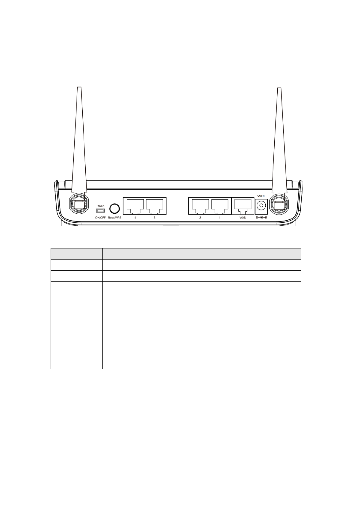
Back Panel
Antenna A Antenna B
Item Name Description
Antenna A/B It is dual band 3dBi antenna.
Radio ON/OFF Switch the button to activate or deactivate the wireless function.
Reset / WPS Reset the router to factory default settings (clear all settings) or
start WPS function. Press this button and hold for 10 seconds to
restore all settings to factory defaults; press this button for less
than 5 seconds once to start 2.4GHz & 5GHz wireless WPS
function.
WAN Wide Area Network (WAN / Internet) po rt.
1 – 4 Local Area Network (LAN) ports 1 to 4.
Power Power connector, connects to A/C power adapter.
16
Page 17
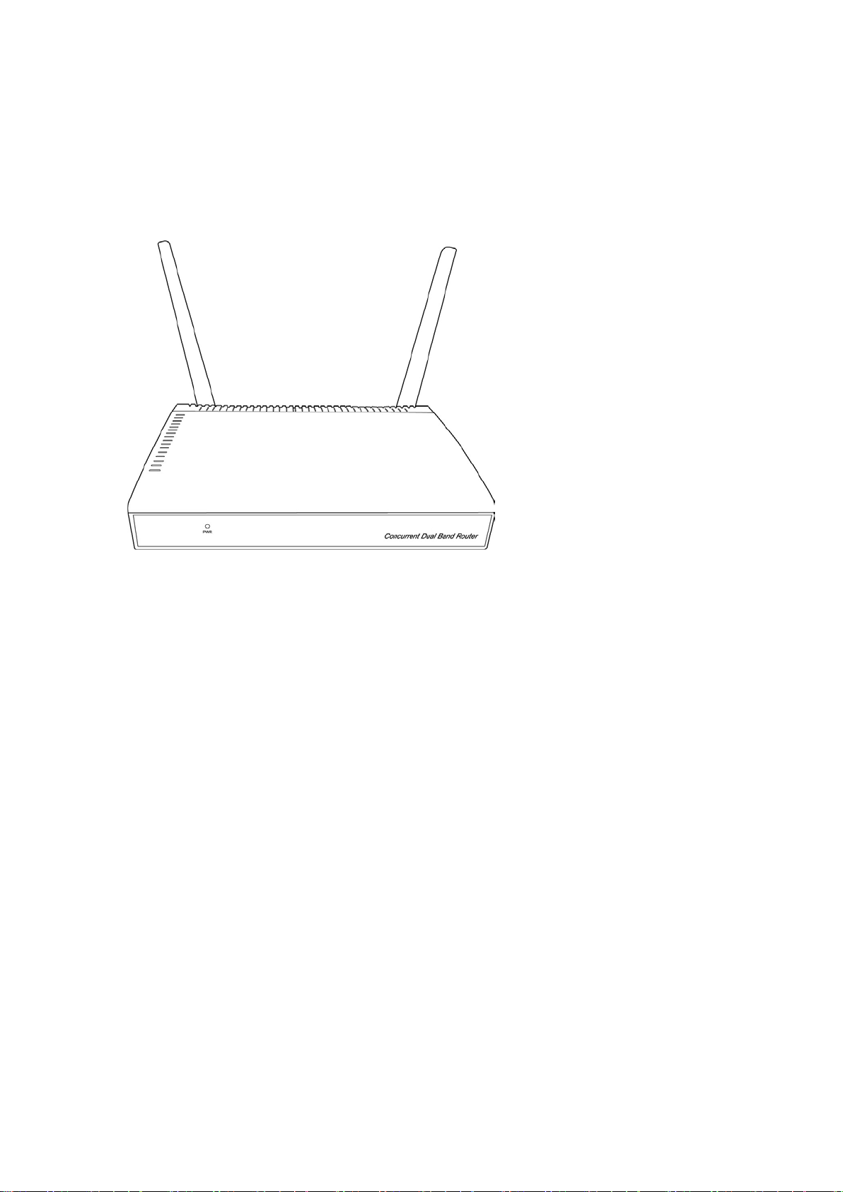
Antenna Angle
Please adjust antenna angle to 45 degree as same as appearance of the
graphic below in order to get the better wire less range.
The front of wireless router will be the strongest signal of wirele ss, try to
adjust front direction of this wireless router to face t o t he othe r w ire le ss
network products.
17
Page 18
Chapter II: System and Network Setup
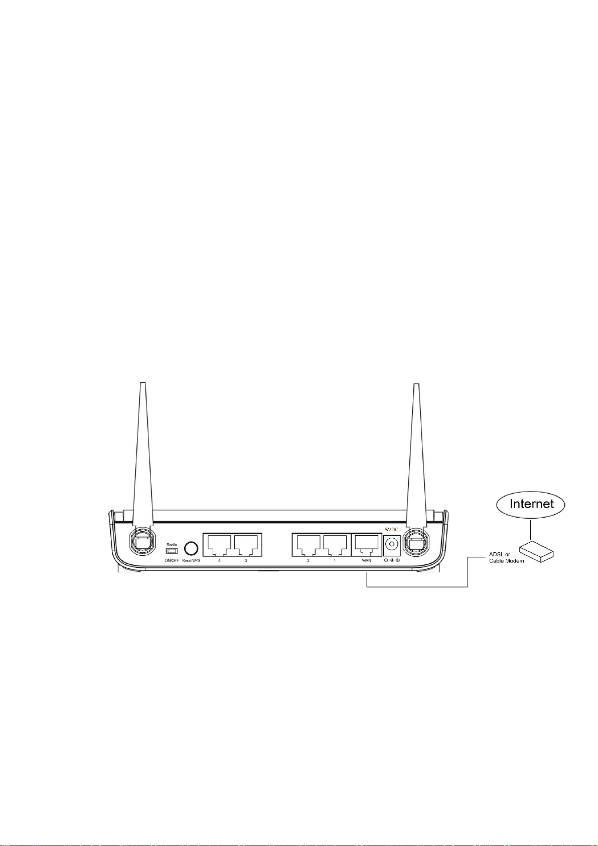
2-1 Build network connection
Please follow the fo llow i ng in str uc t ion to bu il d the ne tw or k con nection
between your new WIRELESS router and your computers, netw ork
devices:
1. Connec t your xDSL / Cable mode m to the WAN port of router by
Ethernet cable.
2. Connec t all your computers, network devices (network-enabled
consumer devices other tha n computers, like Game console, or Switch
/ Hub) to the LAN port of the router.
18
Page 19
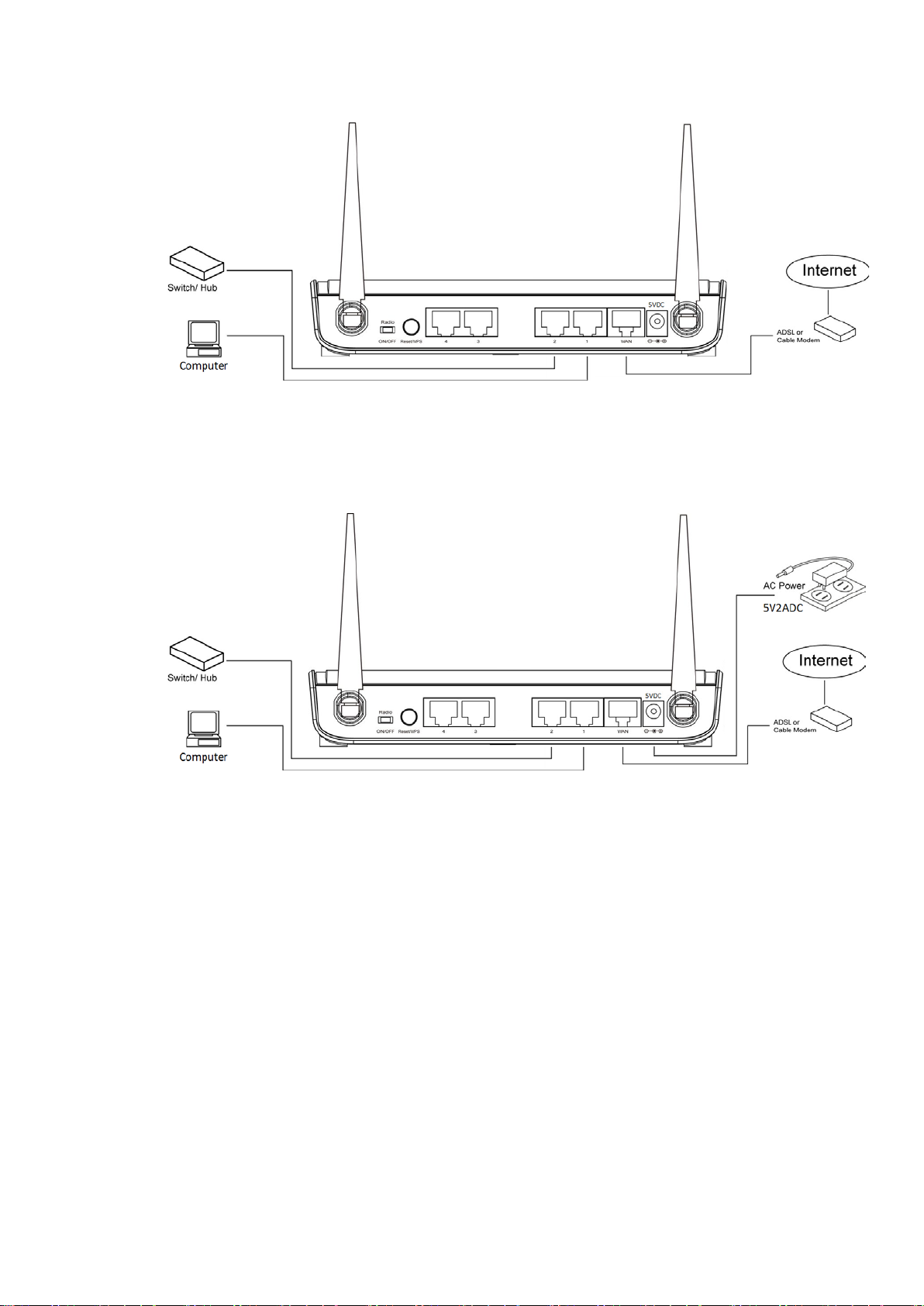
3. Connec t the A/C power ada pter to the wall socket, and then connect it
to the ‘Power’ socket of the router.
4. Please check all LEDs on the front panel. ‘PWR’ LED should be
steadily on, WAN and LAN LEDs should be on if the computer /
network device connected to the respecti ve port of the router is
powered on and correctly c onnected. If PWD LED is not on, or any
LED you expe cted is not on, please recheck the cabling, or jump to
‘4-2 Troublesho otin g’ for possible reasons and solution.
19
Page 20

2-2 Connecting to w i re le ss broadband router by web
browser
After the network connect i on is bui lt, the ne xt ste p y ou sh ould do is
setup the router with proper network parameters, so it can work properly
in your network environment.
Before you c an connect to the router and start configuration
procedures, your computer must be able to get an IP address
automatically (use dynamic IP a ddress). If it’s set t o use static IP address,
or you’re unsure, please follow the following instructions to configure
your computer to u se dynamic IP address:
If the opera ting system of your computer is….
Windows 95/98/Me - please go to section 2-2-1
Windows 2000 - please go t o section 2-2-2
Windows XP - please go to section 2-2-3
Windows Vista/Windows 7 - please go to section 2-2-4
Windows 8 - please go to se ction 2-2-5
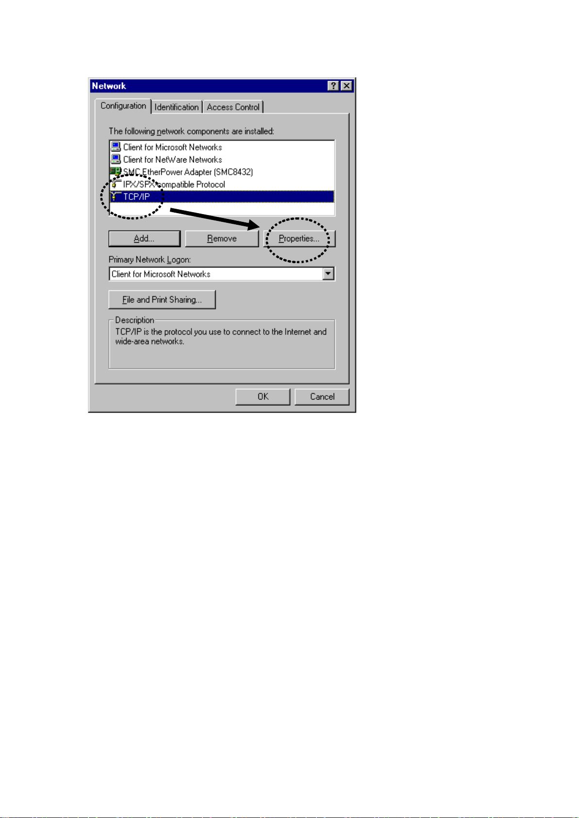
2-2-1 Windows 95/98/Me IP address setup:
1. Click ‘Start’ button (it sho uld be located at lower-left corner of your
computer), then click control panel. Double-click Network ic on, and
Network window will appear. Select ‘TCP/IP’, then click ‘Properties’.
20
Page 21
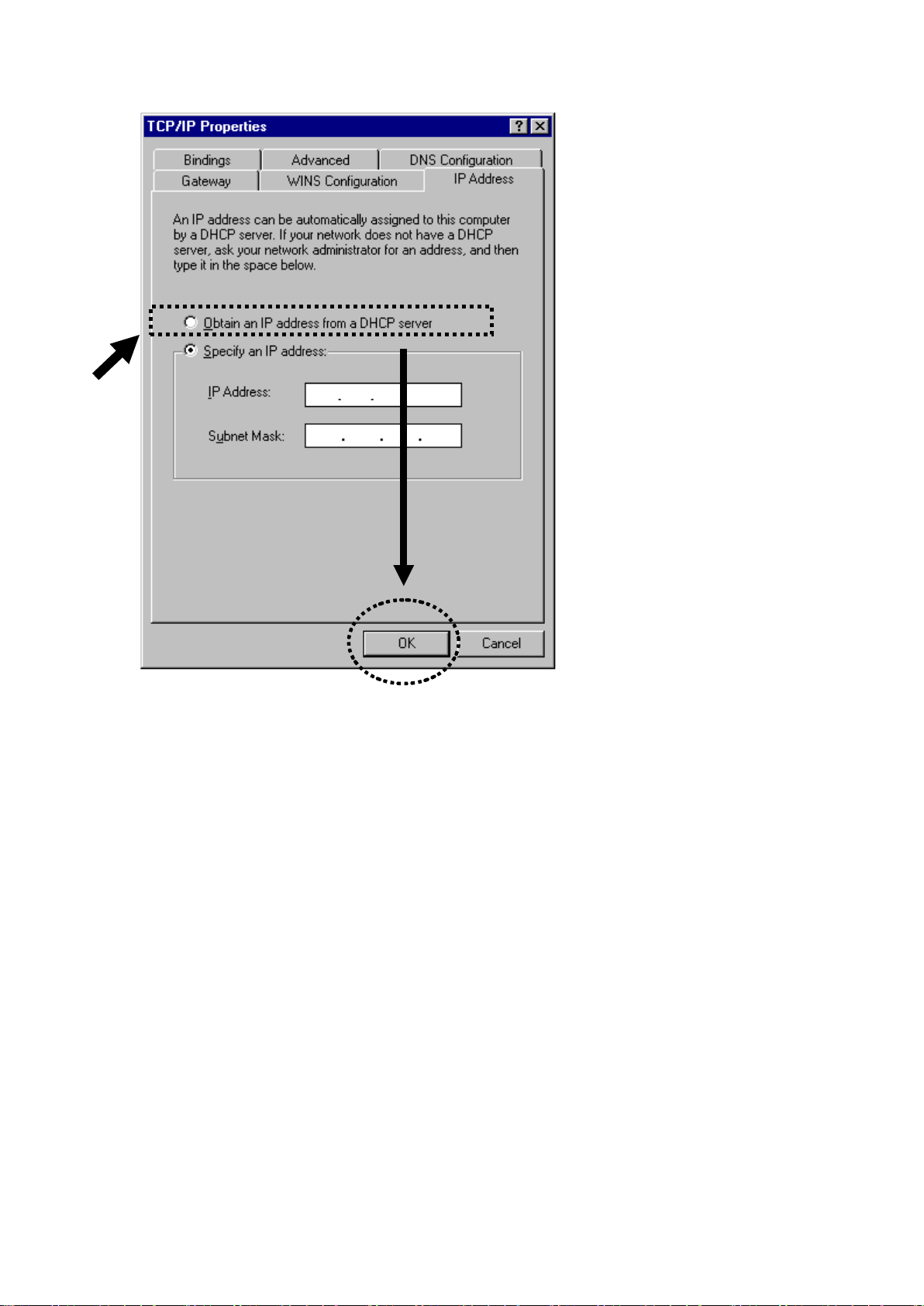
2. Select ‘Obtain an IP address from a DHCP server’ and then clic k ‘OK’.
21
Page 22
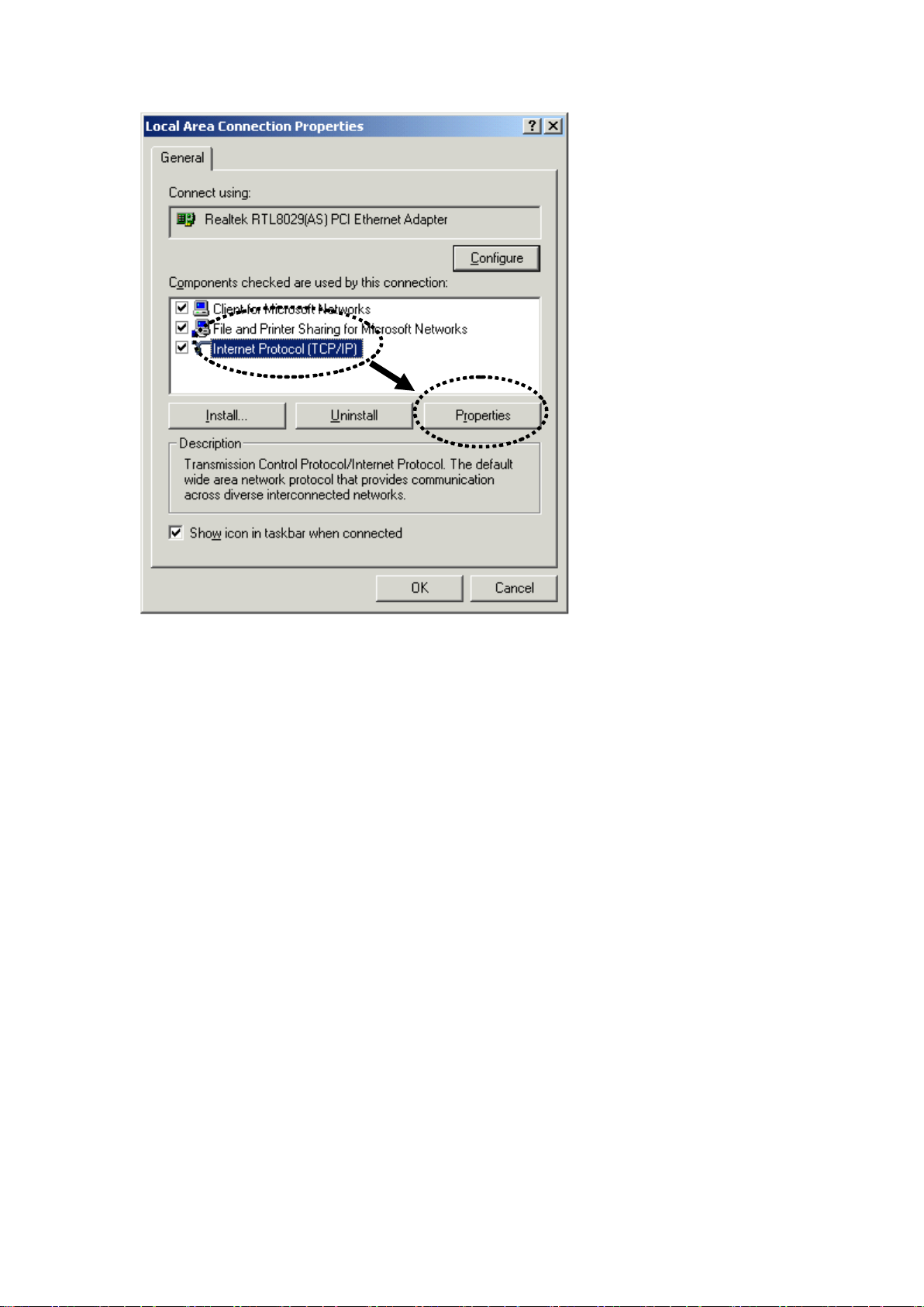
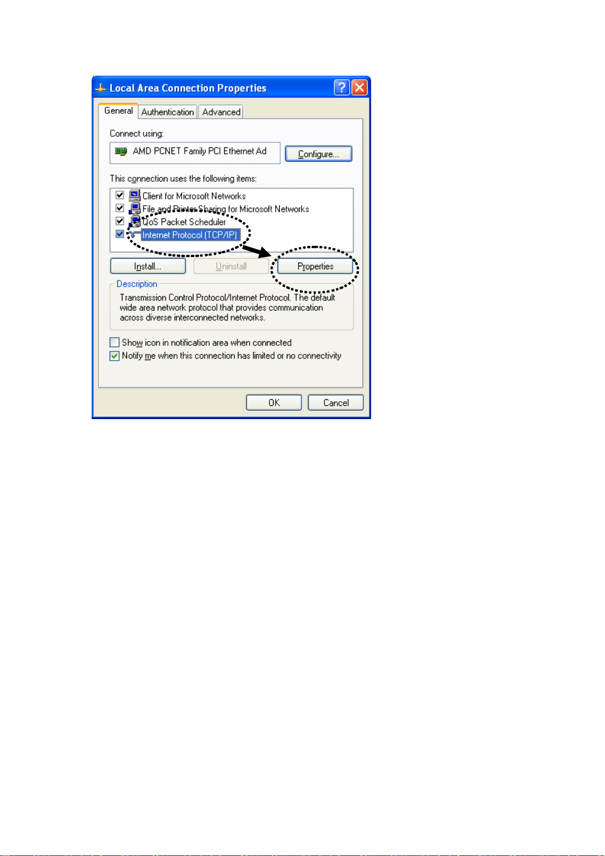
2-2-2 Windows 2000 IP address setup:
1. Click ‘Start’ button (it shoul d be located at lower-left corner of your
computer), then click contr ol pa ne l. Doubl e-click Network and D ial-up
Connections icon; click Local Area Connecti on, and Local Ar ea
Connection Properties window will appear . Select ‘Internet Protocol
(TCP/IP)’ and then click ‘Properties’
22
Page 23
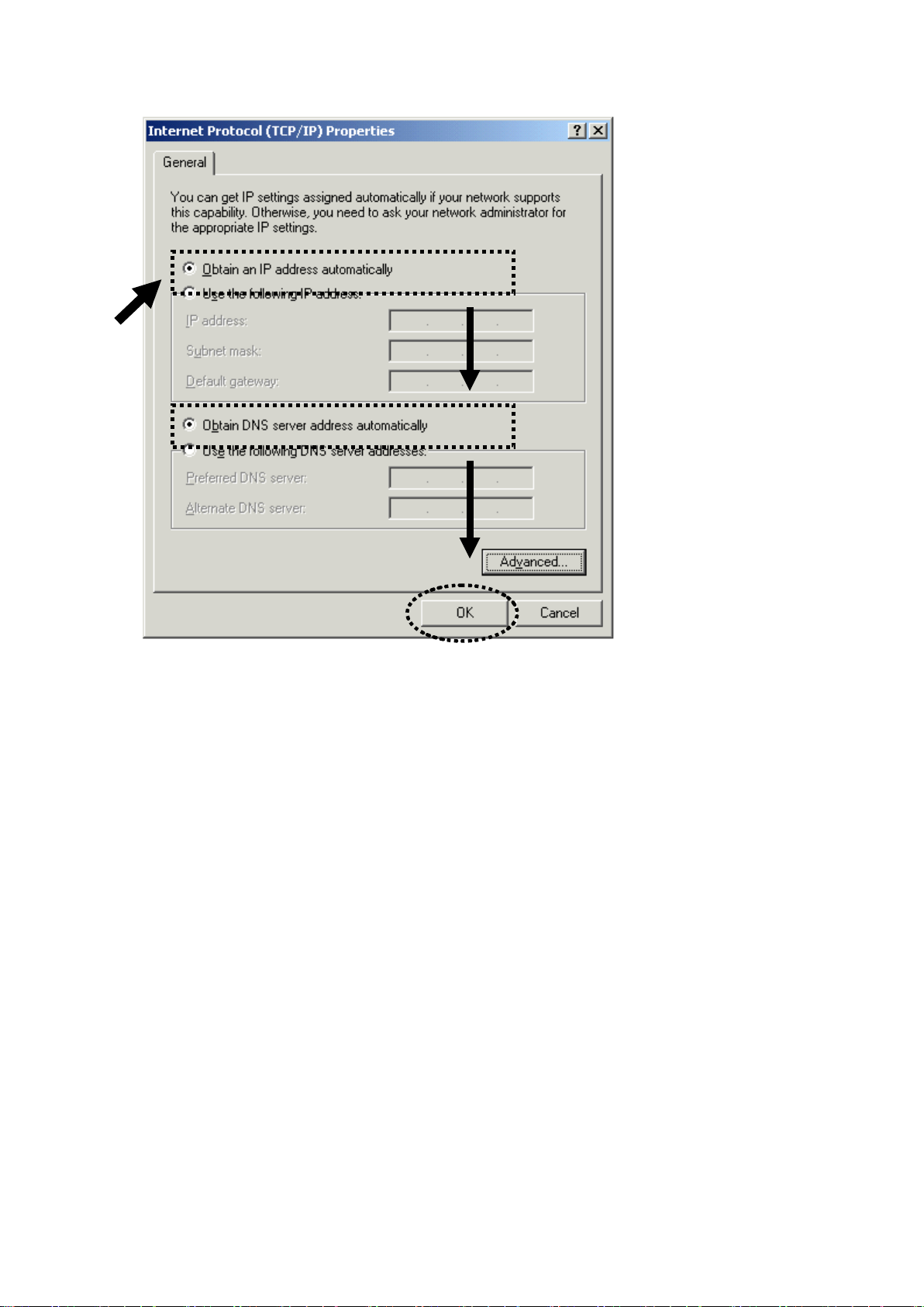
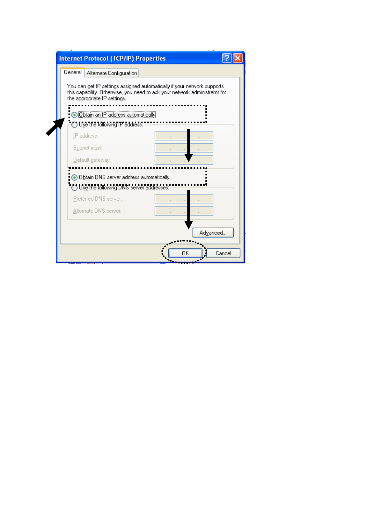
2. Select ‘Obtain an IP address automatically’ and ‘Obtain DNS server
address aut omatically’, then click ‘OK’.
23
Page 24
2-2-3 Windows XP IP address setup:
1. Click ‘Start’ button (it should be located at lower-left cor ner of your
computer), then click control panel. Double-click Network and Interne t
Connections icon, click Network Connections, and then double-click
Local Ar ea Connection, Local Area Connection Properties window will
appear, Select ‘Internet Protocol (TCP/IP)’ and then click ‘Properties’.
24
Page 25
2. Select ‘Obtain an IP address automatically’ and ‘Obtain DNS server
address aut omatically’, then click ‘OK’.
25
Page 26
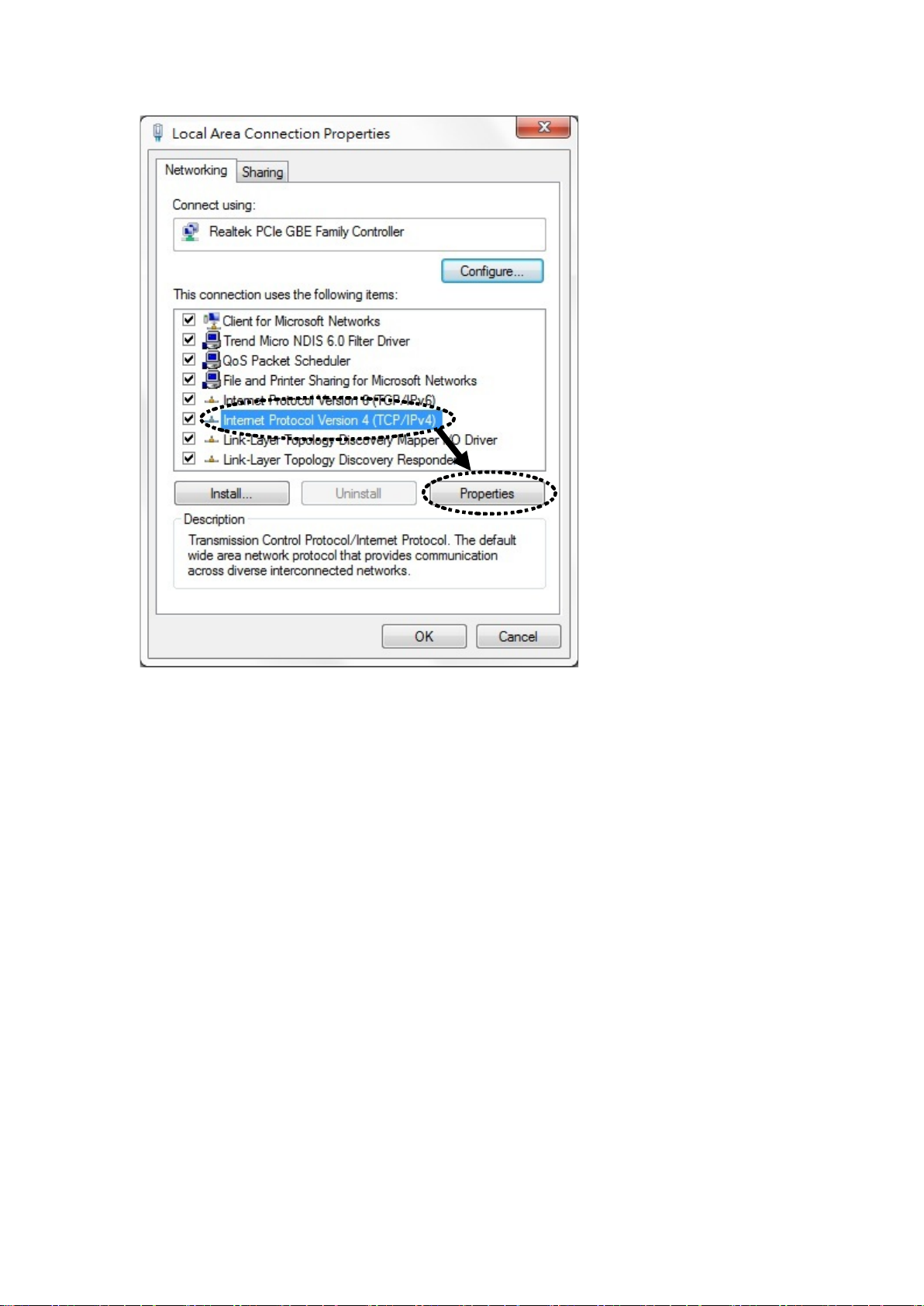
2-2-4 Windows Vista/Windows 7 IP address setup:
1. Click ‘Start’ button (it shoul d be located at lower-left corner of your
computer), then click control panel. Click Network and Sharing Center,
and then click Chan g e ada pte r se tt in gs. Right-click L ocal A rea
Connection, th en sel ect ‘Properties’. Local Area Connect ion Properties
window will appear , select ‘Internet Protocol Version 4 (TCP / IPv4), and
then click ‘Properties’
26
Page 27
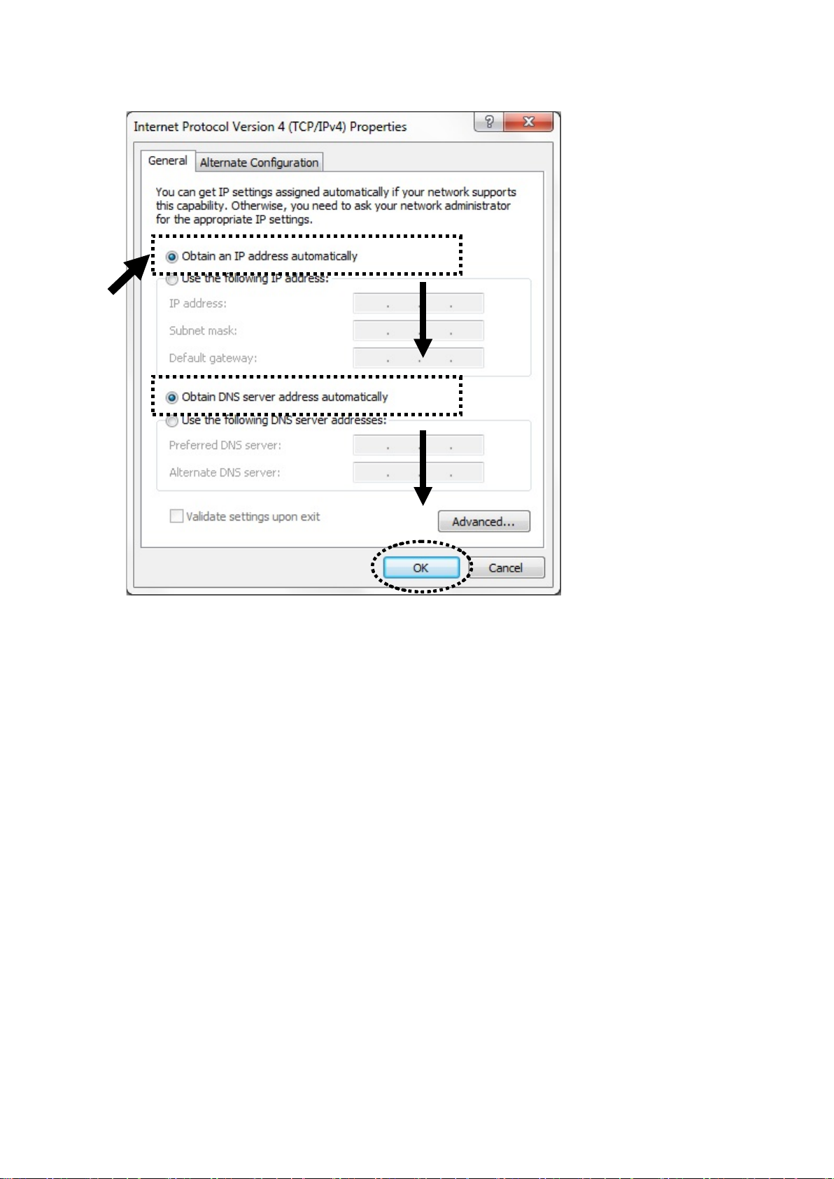
2. Select ‘Obtain an IP address automatically’ and ‘Obtain DNS server
address aut omatically’, then click ‘OK’.
27
Page 28
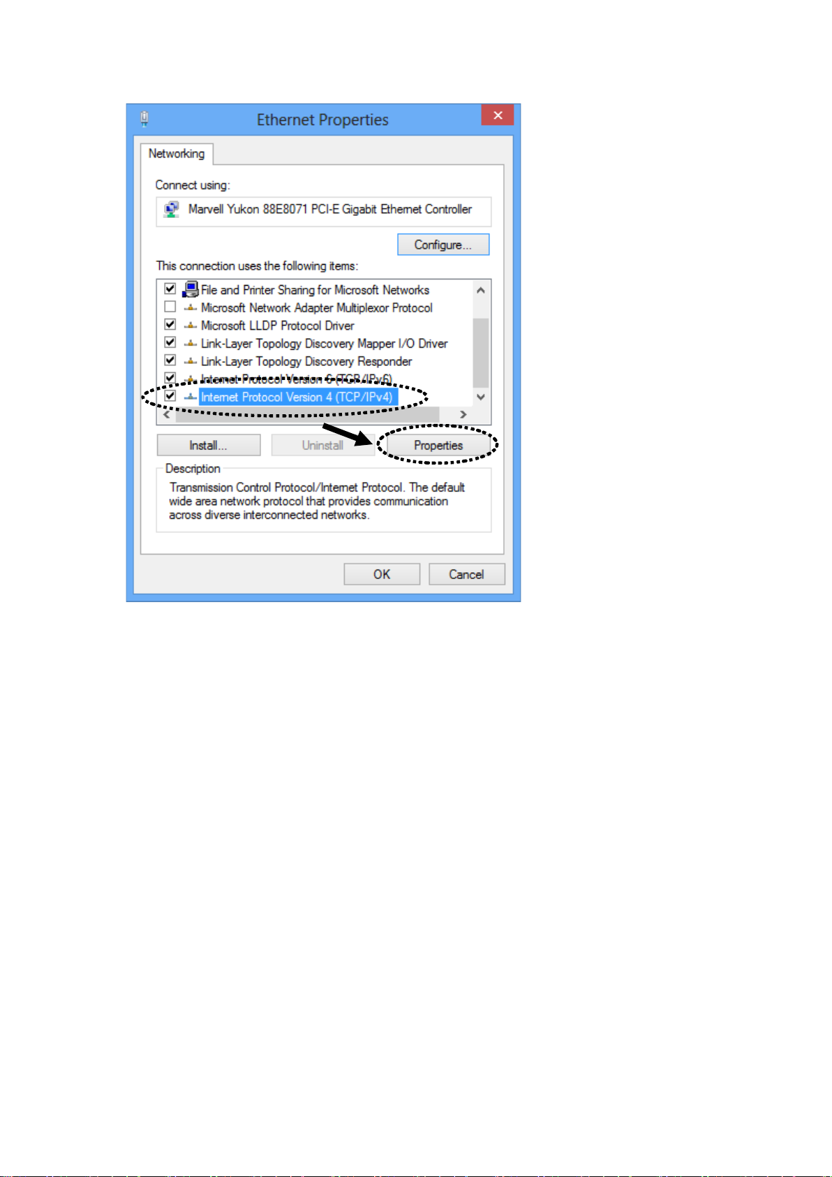
2-2-5 Windows 8 IP address setup:
1. Right-click ‘Start’ button (it should be located at lower-left corner of
your computer), then click control panel. Click Network and Sharing
Center, and then click Change adapt er settings. Right-click Ethernet,
then select ‘Properties’. Ethernet Properties window will appear, select
‘Internet Pr otocol Version 4 (TCP / IP v4), and then click ‘Properties’
28
Page 29
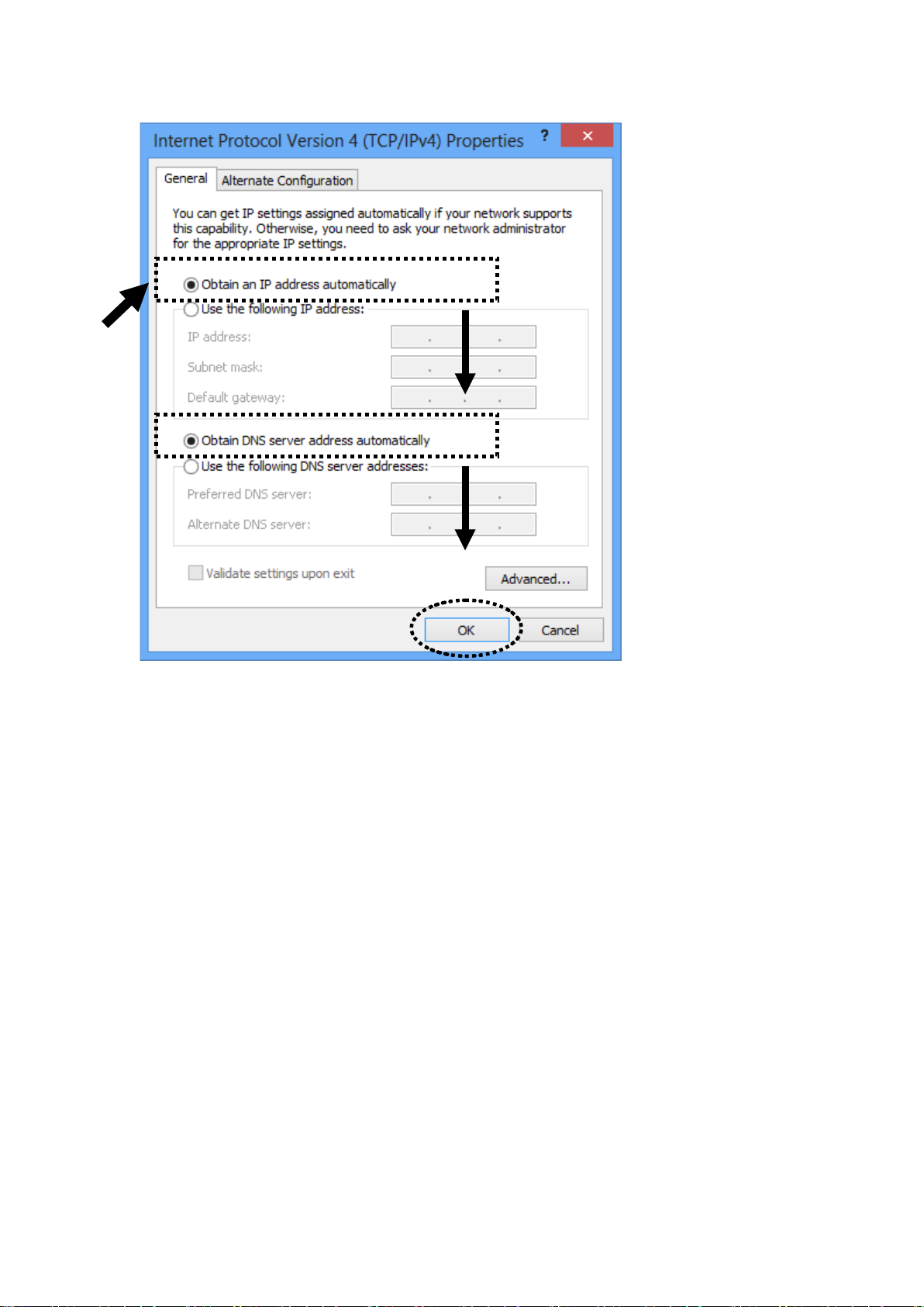
2. Select ‘Obtain an IP address automatically’ and ‘Obtain DNS server
address aut omatically’, then click ‘OK’.
29
Page 30
2-2-6 Router IP address lookup
After the IP address setup is complete, please cl ick ‘start’ -> ‘run’ at the
bottom-lower corner of your desktop:
30
Page 31

Input ‘cm d’, then click ‘OK’
Input ‘ipconfig’, then press ‘Enter’ key. Please check the IP address
followed by ‘Default Gateway’ (In this example, the IP address of router
is 192.168.2.1, please note that this value may be different.)
31
Page 32

NOTE: If the IP address of Gateway is not displayed, or the address followed
by ‘IP Address’ begins with ‘169’, please recheck network connection
between your computer and router, and / or go to the beginning of this
chapter, to recheck every step of network setup procedure.
3. Connect the router’s management interfac e by web browser
After your computer obtained an IP address f rom router, please start your
web browser, and input the IP address of router in address bar. The
following message should be shown:
Please inpu t user name and password in the f ield respectively, default
user name is ‘admin’, and default pa ssw or d is ‘1234’, then press ‘OK’
32
Page 33

button, and you can see the web management interface of th is router:
NOTE: If you can’t see the web management interface, and you’re
being prompted to input user name and password again, it means you
didn’t input username and password correctly. Please retype user
name and password again. If you’re certain about the user name and
password you type are correct, please go to ‘4-2 Troubleshooting’ to
perform a factory reset, to set the password back to default value.
TIP: This page shows the four major setting categories: Quick Setup,
General Setup, Status, and Tools. You can find the shortcut which
leads to these setting categories at the upper-right corner of every
page, and you can jump to another category directly by clicking the
link, and don’t have to go back to the first page.
33
Page 34

2-3 Using ‘Quick Setup’
This router provides a ‘Quick Setup’ procedure, which wi ll help you to
complete all required settings you need to access the Internet in very short
time. Please follow the following instru ctions to complete the ‘Quick
Setup’:
Please go to Quick Setup menu by clicking ‘Quick Setup’ button.
HERE!
And the following message will be displayed:
34
Page 35

1. Set Time Zone
1
2
3
Here are desc riptions of every setup items:
4
Time Zone (1):Please press
button, a drop-down list
will be shown, and you can choose a time zone of
the location you liv e .
T ime Ser ver Input the IP address / host name of time server
Address (2): here
Daylight If the country you live uses daylight sav ing,
Savings(3): please check ‘Enable Function’ box, and ch oo se the
duration of daylight saving.
After you finish with all settings, please c lick ‘Apply’ (4) button.
NOTE: There are several time servers available on internet:
132.163.4.101 (time-a.timefreq.bldrdoc.gov)
If you found that the time of router is incorrect, try another time server.
2. Broadband Type
129.6.15.28 (time-a.nist.gov)
131.107.1.10 (time-nw.nist.gov)
35
Page 36

2. Set Broadband Type
Please choose the broadband (Internet connection) type you’re using in
this page. The re ar e six types of Internet connection, they are:
Cable Modem - Please go to section 2-3-1
Fixed-IP xDSL - Please go to section 2-3-2
PPPoE xDSL - Please go to secti on 2-3-3
PPTP xDSL - Please go to section 2-3-4
L2TP xDSL - Please go to secti on 2-3-5
Telstra Big Pond - Please go to section 2-3-6
If you’re not sure, please contac t your Internet service provider . A wrong
Internet connection type will cause con nection problem, and you will not
be able to connect t o inter ne t.
If you want to go back to previou s ste p, pl ea se press ‘Back’ but t on on t he
bottom of this page.
NOTE: Some service providers use ‘DHCP’ (Dynamic Host
Configuration Protocol) to assign IP address to you. In this case, you
can choose ‘Cable Modem’ as Internet connection type, even you’re
using another connection type, like xDSL. Also, some cable modem
uses PPPoE, so you can choose ‘PPPoE xDSL’ for such cable modem
2-3-1 Setup procedure for ‘Cable Modem’:
connection, even you’re using a cable modem.
36
Page 37

1
2
3
Here are desc riptions of every setup items:
Host Name (1) : Please input the host name of your computer, this is
optional, and only required if your service provider
asks you to do so.
MAC address (2): Please input MAC address of your computer here, if
your servic e provi der only permits computer wit h
certain MA C address to access inte rnet. If you’re
using the computer which used to connect to
Internet via cable modem, you can simply press
‘Clone Mac address’ button to fill the MAC address
field with the MAC address of your computer.
After you finish with all settings, please c lick ‘OK’ (3) button; if you
want to go back to previ o us m enu, clic k ‘Back’.
2-3-2 Setup procedure for ‘Fixed-IP xDSL’:
1
2
3
4
5
Here are desc riptions of every setup items:
37
Page 38

IP Address (1): Please input IP address assigned
by your service provider.
Subnet Mask (2): Please input subnet mask assigned by your service
provider
DNS Address (3): Please input the IP address of D NS server provided
by your serv ice provider.
Default Please input the IP address of DNS server
Gateway (4): provide d by yo ur ser v ice provider.
You must use the addresses provided by your Internet service
provider, wrong setting value will cause connection problem.
When you finish with all settings, press ‘OK’ (5); if you want to go back
to previous menu, click ‘Back’.
NOTE: You can choose this Internet connection method if your
service provider assigns a fixed IP address (also know as static
address) to you, and not using DHCP or PPPoE protocol. Please
contact your service provider for further information.
2-3-3 Setup procedure for ‘PPPoE xDSL’:
38
Page 39

1
2
3
4
5
6
7
Here are desc riptions of every setup items:
User Name (1): Please input user name assigned by your Internet
service provider h ere.
Password (2): Please input the password assigned by your Internet
service provider h ere.
Service Name (3): Please give a name to this Internet service, thi s is
optional
MTU (4): Please input the MTU value of your network
connection here. I f you don’t know, you can use
default value.
Connection Please select the connection type of Interne t
Type (5): connection you wish to use (detailed explanation
listed below).
Idle Time Out (6): Please input idle time out, (detailed explanation
listed below).
When you fin ish with all settings, please click ‘OK’ (7); if you want to go
back to prev ious menu, click ‘Back’.
39
Page 40

MTU - Please use default value if you don’t know what it is, or ask
your service provider for a proper value.
Connection Type - There are 3 options: ‘Continuous’ - keep internet
connection alive, ‘Connect on Demand’ - only connects to Internet
when there’s a connect attempt, and ‘Manual’ - only connects to
Internet when ‘Connect’ button on this page is pressed , and
disconnects when ‘Disconnect’ button is pressed.
Idle Time Out: Specify the time to shutdown internet connect after no
internet activity is detected by minute. This option is only available
when connection type is ‘Connect on Demand’.
2-3-4 Setup procedure for ‘PPTP xDSL’:
PPTP xDSL r equires two kinds of setting: WAN interface setting (setup
IP address) and PPTP setting (PPTP user name and password). Her e we
start from WAN interface setting:
Select the type of how you obtain IP address from your service provider
here. You can choose ‘Obtain an IP address automatically’ (equal to
DHCP, please refer to ‘Cable Modem’ section above), or ‘Use the
following IP address’ (i.e. static IP address).
40
Page 41

WAN interface settings must be correctly set, or the Internet con nection
1
2
9
will fail eve n those settings of PPTP settings are correct. Please contact
your Intern et service provider if you don’t know what you should fill in
these field s.
Now please go to PPTP settings sec tion:
3
4
5
6
7
8
Here are desc riptions of every setup items:
User Name (1): Please input user ID (user name) assigne d by your
Internet serv ice provider he re.
Password (2): Please input the password assigned by your Internet
service provider h ere.
PPTP Please input the IP address of PPTP gateway
Gateway (3): assigned by your Internet service provider here.
Connection Please input the connection ID here, this is
ID (4): optional and you can leave it blank.
MTU (5): Please input the MTU value of your network
connection here. I f you don’t know, you can use
default value.
BEZEQ-ISRAEL (6): Setting item ‘BEZEQ-ISRAEL’ is only required to
41
Page 42

Check if you’re using the servic e provided by
BEZEQ network in Israel.
Connection Please select the connection type of Interne t
type (7): connection you wish to use, please refer to last
section for detailed descriptions.
Idle Time Please input the idle time out of Inter net
Out (8): connection you wish to use, and refer to last sect ion
for detailed descriptions.
When you fin ish with all settings, please click ‘OK (9); if you want to go
back to prev ious menu, click ‘Back’.
2-3-5 Setup procedure for ‘L2TP xDSL’:
L2TP is another popular connection method for xDSL and other Internet
connection types, and all required setting items are the same with PPTP
connection.
Like PPTP, there are two kinds of required setting, we’ll start from ‘WAN
Interface Settings’:
42
Page 43

Please sele ct the type of how you obtain IP address from your servi ce
1
2
6
provider here. You can choose ‘Obtain an IP address automatically’ (equal
to DHCP, please refer to ‘Cable Modem’ section above), or ‘Use the
following IP address’ (equal to static IP address, please refer to ‘PPPoE
xDSL’ section above).
WAN interface settings must be correctly set, or the Internet con nection
will fail eve n those settings of PPTP settings are correct. Please contact
your Intern et service provider if you don’t know what you should fill in
these field s.
Now please go to L2TP settings sec tion:
3
4
5
7
Here are desc riptions of every setup items:
User Name (1): Please input user ID ( user name) assig ned by your
Internet service provider here.
Password (2): Please input the password assigned by your Internet
service provider h ere.
L2TP Gateway (3): Please input the IP address of PPTP gateway
assigned by your Internet service provider here.
MTU (4): Please input the MTU value of your network
connection here. I f you don’t know, you can use
default value.
Connection Please select the connection type of Interne t
43
Page 44

type (5): connection you wish to use, please refer to last
1
2
5
section for deta il ed d escriptions.
Idle Time Please input the idle time out of Internet
Out (6): connection you wish to use, and refer to last sect ion
for detailed descriptions.
When you fin ish with all set tings, please click ‘OK (7); if y ou want to go
back to prev ious menu, click ‘Back’.
2-3-6 Setup procedure for ‘Telstra Big Pond’:
3
4
This setting only works when you’re using Telstra big pond’s network
service in Austral ia. You need to input:
User Name (1): Please input the user name assigne d by Telstra.
Password (2): Please input the password assigned by Telstra.
Assign login Check this box to ch oose log in
server manually (3): server by yourse lf.
Server IP Address(4):Please input the IP address of login server here.
44
Page 45

When you fin ish with all settings, click ‘OK (5); if you want to go back to
previous menu, click ‘Back’.
When all settings are finished, you’ll see the following message displayed
on your web browser:
Please clic k ‘Apply’ button to prepare to restart the router, and you’ll see
this message:
Please wait f or about 40 seconds, then click ‘OK!’ button. You’ll be back
to router m anagement interface again, and the router is r eady with new
settings.
45
Page 46

2-4 Basic Setup
In this chapter, you’ll know how to change the time zone, password, and
remote manage ment settings. Please start your web browser and log onto
router web management interface, then click ‘General Setup’ bu tton o n
the left, or click ‘General Setup’ link at the upper-right corne r of web
management interfac e .
HERE!
46
Page 47

2-4-1 Time zone and time auto-synchronization
Please click ‘System’ menu on the left of web management inte rface, then
click ‘Time Zone’, and t he following message will be displayed on your
web browser :
Please sele ct time zone at ‘Time Zone’ drop-down list, and input the IP
address or h ost name of time server. If you want to enable daylight
savings set ting, please che ck ‘Enable’ box, and set the duration of
daylight se tting. When you finish, click ‘Apply’. You’ll see the following
message displayed on web browser:
Press ‘Continue’ to save the settings made and back to web management
interface ; press ‘Apply’ to save the settings made a nd restart the router so
the settings will take effect after it reboots.
NOTE: You can refer to the instructions given in last chapter: ‘Using
Quick Setup’, for detailed descriptions on time zone settings.
47
Page 48

2-4-2 Change management password
1
Default password of thi s router is 1234, and it’s displayed on the login
prompt when a ccessed from web browser. T here’s a security risk if you
don’t change the default pas sword, since everyone can see i t. This is very
important when you have wireless function enabled.
To change password, please follow the following instructions:
Please clic k ‘System’ menu on the left of web management interface, then
click ‘Password Settings’, and the following message will be d isplayed
on your web browser:
3
Here are descriptions of every setup items:
Current Please input current password here.
Password (1):
New Password (2): Please input new password here.
Confirmed Please input new password here again.
Password (3):
When you fin ish, click ‘Apply’. If you want to keep orig in al pas sw or d
unchanged, click ‘Cancel’.
If the passw ord you typed in ‘New Password’ (2) and ‘Confirmed
Password’ (3) field are not the same, you’ll see the follow ing message:
48
Page 49

Please retype the new password again when you see above message.
If you see the following message:
It means the c ontent in ‘Curre nt Password’ field is wrong, please click
‘OK’ to go back to previous menu, and try to input current pass word
again.
If the current and new passwords are correctly entered, after you click
‘Apply’, you’ll be prompted to input your new password:
Please use new password to enter web management interfa ce again, and
you should be able to login with new password.
49
Page 50

2-4-3 Remote Management
1 2 3
4
This router does not allow management access from Internet, to pre vent
possible security risks (especially when you defined a we ak password, or
didn’t change de fault password). However, you can still management this
router from a specific IP address by enabling the ‘Remote Management’
Function.
To do so, please follow the following inst r uct i on s:
Please clic k ‘System’ menu on the left of web management interface, then
click ‘Remote Managem ent’, and the following message will be
displayed on your web browser:
Here are desc riptions of every setup items:
Host Address (1): Input the IP address of the remote host you wish to
initiate a management access.
Port (2): Yo u ca n defi ne th e po rt number this r out e r sho ul d
expect an incom in g request. If you’re providing a
web service (default port number is 80), you should
try to use other port num be r. You can use the default
port setting ‘8080’, or something like ‘32245’ or
‘1429’. (Any integer bet wee n 1 and 65 5 34 )
Enable (3): Select the field to star t the c onfi g ur ati on.
When you fin ish with all settings, click ‘Apply’, and you’ll see the
50
Page 51

following message displayed on web brow ser:
Press ‘Continue’ to save the settings made and back to web management
interface ; press ‘Apply’ to save the settings made a nd restart the router so
the settings wi ll take effect after it reboots.
NOTE: When you want to manage this router from another computer
on internet, you have to input the IP address and port number of this
router. If your Internet service provider assigns you with a static IP
address, it will not be a problem; but if the IP address your service
provider assigns to you will vary every time you establish an internet
connection, this will be a problem.
Please either asks your service provider to give you a static IP
address, or use dynamic IP to host name mapping services like
DDNS. Please refer to chapter 2-5-8 ‘DDNS client’ for details.
NOTE: Default port number the web browser will use is ‘80’. If the
‘Port’ setting in this page is not ‘80’, you have to assign the port
number in the address bar of web browser manually. For example, if
the IP address of this router is 1.2.3.4, and the port number you set is
8888, you have to input following address in the address bar of web
browser:
http://1.2.3.4:8888
51
Page 52

2-5 Setup Internet Connection (WAN Setup)
1
2
Internet conne c tio n s set u p can be do ne by using ‘Quick Setup’ menu
described in chapter 2-3. However, you can setup WAN connections up
by using WAN configuration menu. You can also set advanced functions
like DDNS (Dynamic DNS) here.
To start configuration, please follow the following instructions:
Please clic k ‘WAN’ menu on the left of web manageme nt interface, and
the following message will be displayed on your web browser:
Please selec t an Internet connection method depend on the type of
connection you’re using. You can either click the connection method on
the left (1) or right (2). If you select the connection m ethod on the right,
please click ‘More Configuration’ button after a method is selected.
Dynamic IP - Please go to section 2-5-1
Static IP - Please go to section 2-5-2
PPPoE - Please go to secti on 2-5-3
PPTP - Please go to section 2-5-4
L2TP - Please go to secti on 2-5-5
Telstra Big Pond - Please go to section 2-5-6
DNS - Please go to section 2-5-7
DDNS - Please go to secti on 2-5-8
WISP - Please go to section 2-5-9
52
Page 53

2-5-1 Setup procedure for ‘Dynamic IP’:
1
2
3
Here are desc riptions of every setup items:
Host Name (1): Please input host name of your computer, this is
optional, and only required if your serv ice provider
asks you to d o so.
MAC Address (2): Please input MAC address of your computer, if your
service provider o nly permits computer with certain
MAC address to access internet. If you’r e us i ng the
computer which used to connect to Internet via
cable modem, you can simply press ‘Clone Mac
address’ button to fill the MAC address field with
the MAC add ress of your computer,
After you finish with all settings, please click ‘Apply’ (3); if you want to
remove and value you enter ed, please click ‘Cancel’.
After you click ‘Apply’, the following message will be displayed on your
web browser :
53
Page 54

4
Please clic k ‘Continue’ (1) to back to previous setup menu; to continue on
router setu p, or click ‘Apply’ to reboot the router so the set tin gs w ill ta ke
effect (Please w a it f or about 40 seconds while router is rebooting).
2-5-2 Setup procedure for ‘Static IP’:
1
2
3
Here are desc riptions of every setup items:
IP Address(1): Please input IP address assigned by your
service provider.
Subnet Mask (2): Please inpu t subnet mask assigned by your
service provider
Default Gateway (3): Please input the IP address of DNS server
54
Page 55

prov i de d by yo ur ser v ice provider.
3
7
After you finish with all settings, please click ‘Apply’ (4) button and the
following message will be displayed on your web browser:
Please clic k ‘Continue’ to back to previous setup menu; to continue on
other setup procedures, or click ‘Apply’ to reboot the router so the
settings will take effect (Please wait for about 40 secon ds whi le r ou ter is
rebooting).
If you want to reset all settings in this page back to previously-saved
value, please cl ic k ‘Cancel’ button.
2-5-3 Setup procedure for ‘PPPoE’:
1
2
4
55
Page 56

Continuous – The connection will be kept always on. If
connect
Connect On-Demand – Onl y connect when y ou want to
Manual – After you have se le ct ed th is o pt ion, you will
to the ISP.
Here are desc riptions of every setup items:
User Name (1): Please input user name assigned by your Internet
service provider h ere.
Password (2): Please input the password assigned by your Internet
service provider h ere.
Service Name (3): Please give a name to this Internet service, this is
optional
MTU (4): Please input the M TU value of your network
connection here. I f you don’t know, you can use
default value.
Connection Please select the connection type of Internet
Type (5): connection you wish to use.
the connecti on is inte rr u pte d, the router will reautomatically.
surf the Interne t. “Idle Time Out” is set to stop the
connection when the network traffic is not sending or
receiving after an idle time.
see the “Connect” button and “Disconnect” button,
click “’Connect” and the router will connect
If you want to stop t h e connection, please c lic k
“Disconnect” button.
Idle Time Out (6): If you have selected the connection type to
“Connect-On-Demand”, please input the idle time
out.
After you finish with all settings, please c lick ‘Apply’ (7) button and the
following message will be displayed on your web browser:
56
Page 57

Please clic k ‘Continue’ to back to previous setup menu; to continue on
other setup procedures, or click ‘Apply’ to reboot the router so the
settings will take effect (Please wait for about 40 secon ds whi le r ou ter is
rebooting).
If you want to reset all settings in this page back to previously-saved
value, please cl ic k ‘Cancel’ button.
2-5-4 Setup procedure for ‘PPTP’:
PPTP requires two kinds of setting : WAN interface setting (setup IP
address) and PPTP setting (PPTP user name and password). Here we start
from WAN interface setting:
Select the type of how you obtain IP address from your service provider
here. You can choose ‘Obtain an IP address automatically’ (equal to
DHCP, please refer to ‘Cable Modem’ section above), or ‘Use the
following IP address’ (i.e. static IP address)
57
Page 58

1
2
9
WAN interface settings must be correctly set, or the Internet con nection
will fail eve n those settings of PPTP settings are correct. Please contact
your Intern et service provider if you don’t know what you should fill in
these field s.
Now please go to PPTP settings sec tion:
3
4
5
6
7
8
Here are desc riptions of every setup items:
User Name (1): Please input user ID (user name) assigned by your
Internet se rvice pr ov i der he re.
Password (2): Please input the password assigned by your Internet
service provider h ere.
PPTP Gateway (3): Please input the IP address of PPTP gateway
assigned by your Internet service provider here.
Connection ID (4): Please input the connection ID here, this is optional
and you can leave it blank.
MTU (5): Please input the M TU value of your network
connection here. I f you don’t know, you can use
default value.
58
Page 59

BEZEQ-ISRAEL (6): If you are connecting to the BEZEQ network in
Israel. Please enable this f unc t io n.
Connection Please select the connection type of Internet
type (7): connection you wish to use, please refer to section
2-5-3 for detailed descriptions.
Idle Time Out (8): Please inpu t the idle time out of Internet c onnection
you wish to use, and refer to section 2-5-3 for
detailed descriptions.
When you fin ish with all set tings, please click ‘Apply’ (9) button and the
following message will be displayed on your web browser:
Please clic k ‘Continue’ to back to previous setup menu; to continue on
other setup procedures, or click ‘Apply’ to reboot the router so the
settings will take effect (Please wait for about 40 seconds w hile rou ter is
rebooting).
If you want to reset all settings in this page back to previously-saved
value, please cl ic k ‘Cancel’ button.
2-5-5 Setup procedure for ‘L2TP’:
59
Page 60

1
2
3
6
4
5
7
Here are desc riptions of every setup items:
User ID (1): Please input user ID (user name) assigned by your
Internet serv ice provider he re.
Password (2): Please input the password assigned by your Internet
service provider h ere.
L2TP Please input the IP address of PPTP gateway
Gateway (3): assigned by yo ur Internet serv ice pr ovider here.
MTU (4): Please input t he MTU value of your network con nection
here. If you don’t know, you can use def ault value.
Connection Please select the connection type of Internet connection
type (5): you wish to use, p lease refer to section 2-5-3 for detailed
descriptions.
Idle Time Please input the idle time out of Internet connection
Out (6): you wish to use, and refer to section 2-5-3 for detail e d
descriptions.
When you fin ish with all set tings, please click ‘Apply’ (7) button and the
following message will be displayed on your web browser:
60
Page 61

1
2
3
Please clic k ‘Continue’ to back to previous setup menu; to continue on
other setup procedures, or click ‘Apply’ to reboot the router so the
settings will take effect (Please wait for about 40 seconds while rou ter is
rebooting).
If you want to reset all settings in this page back to previously-saved
value, please cl ic k ‘Cancel’ button.
2-5-6 Setup procedure for ‘Telstra Big Pond’:
4
5
This setting only works when you’re using Telstra big pond’s network
service in Austral ia. You need to input:
User Name (1): Please input the user name ass ig ne d by Telstra.
Password (2): Please input the password assigned by Telstra.
61
Page 62

Assign login Check this box to ch oose login server by yourself.
server manually (3):
Server IP Address (4):Please input the IP address of login server here.
When you fin ish with all set tings, click ‘Apply’ (5) button and the
following message will be displayed on your web browser:
Please clic k ‘Continue’ to back to previous setup menu; to continue on
other setup procedures, or click ‘Apply’ to reboot the router so the
settings will take effect (Please wait for about 40 seconds while rou ter is
rebooting).
If you want to reset all settings in this page back to previously-saved
value, please cl ic k ‘Cancel’ button.
2-5-7 Setup procedure for ‘DNS’:
If you select ‘Dynamic IP’ or ‘PPPoE’ as Internet connection method, at
least one DNS server’s IP address should be assigned automatically.
However, if you have preferred DNS server, or your service provide r
didn’t assign the IP address of DNS server because of any reason, you can
input the IP address of DNS server here.
62
Page 63

1 2 3
Here are desc riptions of every setup items:
DNS Address (1): Please i nput the IP address of DNS server provided
by your serv ice provider.
Secondary Please input the IP address of another DNS
DNS Address (2): server provided by your service provider, this is
optional.
NOTE: Only IP ad dre ss can be ent ered her e; DO NOT use the hostname
of DNS server! (i.e. only numeric characters and dots are accepted)
10.20.30.40……………………………………………………………… Correct
dns.serviceprovider.com…………………………………………... Incorrect
After you finish with all settings, please c lick ‘Apply’ (3) button and the
following message will be displayed on your web browser:
Please clic k ‘Continue’ to back to previous setup menu; to continue on
other setup procedures, or click ‘Apply’ to reboot the router so the
63
Page 64

settings will take effect (Please wait for about 40 seconds while rou ter is
rebooting).
If you want to reset all settings in this page back to pr ev i ously -saved
value, please cl ic k ‘Cancel’ button.
2-5-8 Setup procedure for ‘DDNS’:
DDNS (Dynamic DNS) is an IP-to-Hostname ma pping service for those
Internet users who don’t have a static (fixed) IP address. It will be a
problem when such user wants to provide se rvices to other u sers on
Internet, because their IP address will vary ever y time when connected to
Internet, and other user will not be able t o know the IP address t hey’re
using at a certain time.
This router supports DDNS service of several service providers, for
example:
DynDNS (
TZO (
http://www.dyndns.org)
http://www.tzo.com)
Please go to one of DDNS service provider’s webpage listed above, and
get a free DD NS account by the instructions given on their webpage.
64
Page 65

1
2
3
4 5 6
Here are desc riptions of every setup items:
Dynamic DNS (1): If you want to enable DDNS fu nction, please select
‘Enabled’; otherwise ple ase select ‘Disabled’.
Provider (2): Select your DDNS service provider here.
Domain Name (3): Input the domain name you’ve obtained from DDNS
service provider.
Account / Input account or email of DDN S registration.
E-Mail (4):
Password / Key (5): Input DDNS service password or key.
After you finish with all settings, please c lick ‘Apply’ (6) button and the
following message will be displayed on your web browser:
65
Page 66

Please clic k ‘Continue’ to back to previous setup menu; to continue on
2
3
4
5
7
6
other setup procedures, or click ‘Apply’ to reboot the router so the
settings will take effect (Please wait for about 40 seconds while rou ter is
rebooting).
If you want to reset all settings in this page back to previously-saved
value, please cl ic k ‘Cancel’ button.
2-5-9 Setup procedure for ‘WISP’:
If your netw ork service provided by your service provider is through
wireless ne twork, please select this mode. Af ter you have connected the
router to the access point of service provider wirelessly, please setup the
WAN connection type in WAN page.
1
Here are desc riptions of every setup items:
Disable/Enable/ There are three selections for disable or disable
Enable (Station wireless ISP functions.
Mode Only) (1):
Disable: dis able this fu nc ti o n.
Enable: enable this function and the router can also
act as an acce ss point and all ow the wireless clients
66
Page 67

to associate to it for WAN access service.
Note: In this mode, if you are informed by your
wireless ISP that the wireless settings of the
access point is changed, please configure th e
router in this page for matching the settings.
Enable (Station Mode Only): enable this function
and the router wil l act as a wireless clien t and after
connecting to W ISP netw ork devic es, WAN access
service will be built up through wi reless. Users are
allowed to access the WAN service thro ug h wi red
Ethernet or through anot her wi reless ban d.
SSID (2): This is the name of wireless netwo rk . Input the SSID
name that yo ur wire less ISP provides to you.
Channel Number (3):This is the radio fr equency used to transmit and
receive the wireless si gnal. The wi reless devices in
the same network s ho uld fo ll ow the same se tt ing.
Select the channel designated by your wireless ISP.
Wireless Band (4): Check your Wireless ISP service provider either
2.4GHz or 5GHz wireless ban d is use d for the
network and then select the wireless band here.
Site Survey (5): Click ‘Select Site Survey’ button, then a “Wireless
Site Survey Table” will pop up. It wi ll li st all
available acc e ss poi n ts ne arby. Select the access
point designated by your wireless ISP in the table
and the r ou ter will join wireless network through
this access poin t.
Security Setting (6): If the access point enables wire less security, you
have to follow the same settings in order to acces s
the access point. Click to set security settings for
this connection (Please go to sec ti on ‘2-7-3
Wire less Security’ for detail ed in st r uct i ons) .
67
Page 68

After you finish with all settings, please c lick ‘Apply’ (7) button and the
following message will be displayed on your web browser:
Please click ‘Continue’ to back to previous setup menu; to continue on
other setup procedures, or click ‘Apply’ to reboot the router so the
settings will take effect (Please wait for about 40 seconds while rou ter is
rebooting).
If you want to reset all settings in this page back to previously-saved
value, please cl ic k ‘Cancel’ button.
68
Page 69

2-6 Wired LAN Configurations
worry! We will provide recommended setup values below.
Before all computers using w ired Ethernet connection (i. e. those
computers connect to this r outer’s LAN port 1 to 4 by Ethernet cable) can
communicate with each other and ac cess internet, they must have a valid
IP address.
There are tw o ways to assig n IP addresses to computers: static IP address
(set the IP address for every computer manually), and dynamic I P address
(IP address of computers will be assigned by router automatically. It’s
recommended for most of computers to use dynamic IP address, it w ill
save a lot of time on setting IP addresses for every computer, especially
when there are a lot o f com puter s in your network; for servers and
network devices which will provide services to other computer and users
that come from Internet, static IP address should be used, so other
computes can locate the server.
Suggestions on IP address numbering plan:
If you have no idea on how to define an IP address plan for your
network, here are some suggestions.
1. A valid IP address has 4 fields: a.b.c.d, for most of home and
company users, it’s suggested to use 192.168.c.d, where c is
an integer between 0 and 254, and d is an integer between 1
and 254. This router is capable to work with up to 253 clients,
so you can set ‘d’ field of IP address of router as 1 or 254 (or
any number between 1 an d 254) , an d pick a number between 0
and 254 for field ‘c’.
2. In most cases, you should use ‘255.255.255.0’ as subnet mask,
which allows up to 253 clients (this also meets router’s
capability of working with up to 253 clients).
3. For all servers and network devices which will provide
services to other people (like Internet service, print service,
and file service), they should use static IP address. Give each
of them a unique number between 1 and 253, and maintain a
list, so everyone can locate those servers easily.
4. For computers which are not dedicated to provide specific
service to others, they should use dynamic IP address.
If you don’t really understand the descr ip t io ns l ist ed ab o v e, d on’t
69
Page 70

Please follow the following instructions to set wired LAN parameters:
Please clic k ‘LAN’ menu on the left of web management interface, there
are three setup groups here: ‘LAN IP’, ‘DHCP Server’, and ‘Static DHCP
Leases Table’. Here are setup instr uctions for each of them:
2-6-1 LAN IP section:
1
2
3
4
Here are desc riptions of every setup item s:
IP address (1): Please input the IP address of this router.
Subnet Mask (2): Please input subnet m ask fo r th is net wo rk .
802.1d If you wish to activate 802.1d spanning tr ee
Spanning Tree (3): function, select ‘Enabled’ for setup item ‘802.1d
Spanning Tr ee’, or set it to ‘Disabled’
DHCP Server (4): If you want to activate DHCP server function of this
router, select ‘Enabled’, or set it to ‘Disabled’.
Recommended Value if you don’t know what to fill:
IP Address: 192.168.2.1
Subnet Mask: 255.255.255.0
802.1d Spanning Tree: Disabled
DHCP Server: Enabled
70
Page 71

2-6-2 DHCP Server:
1
2
3
4
These settings are only available when ‘DHCP Server’ in ‘LAN IP’
section is ‘Enabled’, and here are descr iptions of every setup items:
Lease Time (1): Please choose a lease time (the durati on th at eve ry
computer can keep a specifi c IP address) of every
IP address assigned by this router from dropdown
menu.
Start IP (2): Please input the start IP address of the IP range.
End IP (3): Please input the end IP address of the IP range.
Domain Name (4): If you wish, you can also optionally input the
domain name for your networ k. This is optional.
Recommended Value if you don’t know what to fill:
Lease Ti me: Two Weeks (or ‘Forever’, if you have less than 20 computers)
St ar t IP: 192 . 16 8.2.100
End IP: 192.168.2.200
Domain Name: (leave it blank)
NOTE:
1. The number of the last field (mentioned ‘d’ field) of ‘End IP’ must be
greater than ‘Start IP’, and can not the same with router’s IP address.
2. The former three fields of IP address of ‘Start IP’, ‘End IP’, and ‘IP
Address of ‘LAN IP’ section (mentioned ‘a’, ‘b’, and ‘c’ field) should be
the same.
3. These settings will affect wireless clients too.
71
Page 72

2-6-3 Static DHCP Leases Table:
This functi on allows you to assign a static IP address to a specific
computer for ever, so you don’t have to set the IP address for a
computer, and still enjoy the benefit of using DHCP server. Maximum
16 static IP addresses can be assigned here.
(If you set ‘Lease T im e’ to ‘forever’ in ‘DHCP Server’ secti on, you can
also assign an IP ad dress to a speci fic computer permanen tl y, however,
you will not be able to assi gn a cert ai n IP address to a specific
computer, since IP addresses will be assigned in random order by this
way).
1
2 3 4
Here are desc riptions of every setup items:
Enable Static Check this box to enable t his fun ct io n,
DHCP Leases (1): otherwise uncheck it to disable this function.
MAC Address (2): Input the MA C address of the compu ter or
network device (total 12 characters, wit h
character from 0 t o 9, and from a to f, like
‘001122aabbcc’)
IP address (3): Input the IP address you want to assig n to this
computer or netw ork dev ic e
‘Add’ (4): After you inputted MAC address and IP address
pair, click this button to add the pair to static
DHCP leases table.
If you want to remove all char acters you just entered, click ‘Clear’.
72
Page 73

After you clicked ‘Add’, the MAC address and IP addre ss mapping
will be added to ‘Static DHCP Leases Table’ section.
1
2
3
If you want to delete a specific item, please check the ‘Select’ box of a
MAC address and IP address mapping (1), then clic k ‘Delete Selected’
button (2); if you want to delete all mappings, click ‘Delete All’ (3).
After you finish all LAN settings, please c lick ‘Apply’ button on this
page. After you click ‘Apply’, the following message will be displayed on
your web browser:
Please clic k ‘Continue’ to back to previous setup menu; to continue on
router setup, or c lick ‘Apply’ to reboot the router so the settin gs w ill ta ke
effect (Please w a it f or about 40 seconds while router is rebooting).
73
Page 74

2-7 Wireless LAN Configurations
If your computer, P DA, game console, or other network devices which
is equipped w ith wireless network interface, you can use the wireless
function of this router to let them connect to Internet and share
resources with other computers with wired-LAN connection. You can
also use the built-in se curity functions to protect your network from
being intruded by malicious intruders.
This router supports both 2.4GHz and 5GHz wireless bands
simultaneously; the wireless settings for both wireless bands are almost
the same. The f ollowing secti ons will only hi ghlight the different
descriptions between these two sele ct i on s.
Enter into ‘General Setup’ page, select ‘2.4GHz Wireless’ or ‘5GHz
Wireless’ to configure the wire less settings for the different wireless
radio.
HERE!
Please follow the following instructions to set wireless parameters:
Please click ‘2.4GHz Wireless’ or ‘5GHz Wireless’ menu on the left of
74
Page 75

web management interface, and the following message w ill be displayed
on your web browser. You must enable wireless function of t his router, or
the wireles s interface of this router wil l n ot function. Please select
‘Enable’ (1), then click ‘Apply’ (2) button.
If you want to disable wireless function, please switch hardwa re butt o n
to turn off wireless ra dio at rear panel of device.
1 2
After you click ‘Apply’(2), the following message will be displayed on
your web browser:
Please clic k ‘Continue’ to back to previous setup menu; to continue on
other setup proc ed ures, or click ‘Apply’ to reboot the router s o the
settings will take effect (Please wait for about 40 seconds while rou ter is
rebooting).
2-7-1 Basic Wireless Settings
Please clic k ‘ 2.4GH z Wireless’ or ‘5GHz Wireless’ menu on the left of
75
Page 76

web management interface, then click ‘Basic Settings’, and the following
message will be displayed on your web browser:
2.4GHz Wireless
5GHz W ir eless
This wireless route r can be work in 6 modes:
a. Access Point: Standard wireless AP .
b. Station-Infrastructure: Configure the router to Ethernet devic e suc h us
TV, Game player, HDD&DVD to enable the E thernet device be a
wireless station.
c. AP Bridge-Point to Point: Connect this router with another w ireless
router, to expand the scope of network.
76
Page 77

d. AP Bridge-Point to Multi-Point: Connect this r outer with up t o four
other wireless routers, to expand the scope of network.
e. AP Bridge-WDS: Connect this route r with up to four WDS-capable
wireless ro uters, to expand the scope of network.
f. Universal Repeater: The router can act as Station and AP at the same
time. It can use Station function to connect to a Root AP and use AP
function to service all wireless stations within its coverage.
NOTE: For ‘AP Bridge-Point to Point’ and ‘AP Bridge-Point to
Multi-Point’ mode, wireless router is operated in wireless bridge
dedicated mode – wireless router is only used to expand the scope of
network, and no wireless clients will be accepted. If you want to use
your wireless router to expand the scope of network, and also accept
wireless clients, please select ‘AP Bridge-WDS’ or ‘Universal
Repeater‘ mode.
Please sele ct a proper oper ation mode you want to use from ‘Mode’
dropdown menu (1), and continue on other operation mode specific
settings:
Access Point - Please go to section 2-7-1-1
Station-Infrastructure - Please go to section 2-7-1-2
AP Bridge-Point to Point - Please go to section 2-7-1-3
AP Bridge-Point to Mult i-Point - Please go to sec ti on 2-7-1-4
AP Bridge-WDS - Please go to section 2-7-1-5
Universal Repeater - Please go to section 2-7-1-6
2-7-1-1 Setup procedure for ‘Access Point’:
77
Page 78

Please sele ct the radio band you want to use from ‘Band’ dropdow n menu
1 2 3
1 2 3
(2), and the following message will be displayed:
2.4GHz Access Poin t Settings
4
5
5GHz Access Point Settings
4
5
Here are desc riptions of every setup items:
Band (2): Please sele ct th e rad i o band from one of following
options:
2.4GHz Band
2.4 GHz (B): this mode only allows 8 02. 11b
wireless ne twork client to connect this ro uter
(maximum transfer rate 11Mbps).
78
Page 79

2.4 GHz (N): this mode only allows 802.11n
wireless ne twork client to connect this ro uter
(maximum transfer rate 300Mbps).
2.4 GHz (B+G): this mode only allows 802.11b and
802.11g wireless network client to connect this
router (ma ximum transfer rate 11Mbps for 802.11b
clients, and maximum 54Mbps for 802.11g client s).
2.4 GHz (G): this mode only allows 802. 11g
wireless ne twork client to connect this ro uter
(maximum transfer rate 54Mbps).
2.4 GHz (B+G+N): this mode allows 802.11b,
802.1 1 g, and 80 2.11n wireless networ k client to
connect this router (maximum transfer ra te 11M bps
for 802.11b clients, maximum 54Mbps for 802.11g
clients, and maximum 300M bps f or 80 2. 11n
clients).
5GHz Band
5GHz (A): this mode a ll ows 8 02. 11a wireless
network clie nt to c onnect this router (maximum
transfer rate 54Mbps for 802.11a clients).
5GHz (N): this mode a ll ows 8 02. 11n wireless
network client to connect this router (maximum
transfer rate 300Mbps for 802.11n clients).
5GHz (A+N): this mode allows 802.11a and
802.11n wireless ne twork client to connect this
router (ma ximum transfer rate 54Mbps for 802.11a
clients, and maximum 300M bps f or 80 2. 11n
clients).
5GHz (AC): this mode a ll ows 8 02. 11ac wireless
network clie nt to c onnect this router (maximum
transfer rate 867Mbps for 802.11ac clients).
79
Page 80

5GHz (N+AC): this mode allows 802.11n and
802.11ac wireless network client to connect this
router (ma ximum transfer rate 300Mbps for 802.11n
clients, and maximum 867M b ps for 80 2. 11ac
clients).
5GHz (A+N+AC): this mode allows 802.11a,
802.11n and 802.11ac wireless network client to
connect this router (maximum transfer ra te 54Mbps
for 802.11a clients, maximum 300Mbps for 802.1 1n
clients, and maximum 867M b ps for 80 2. 11ac
clients).
NOTE: For 802.11n/11ac mode: The router is operating in a 2T2R
Spatial Multiplexing MIMO configuration.
SSID (3): This is the name of wireless router. You can type any
alphanumerical characters here, maximum 32
characters. SSID is used to identify your o wn
wire l es s router from others whe n the re are other
wireless routers in the same area. Defau lt SSID is
‘default’, it’s recommended to ch a nge de fa ul t SSID
value to the one which is me aningful to you, like
myhome, office_room1, etc.
Channel Number (4): Please select a channel from the dropdown list of
‘Channel Number’. You can choose any channel
number you want to use, and a lmost all wireless
clients can locate the channel you’r e us i ng
automatically without any problem. However, it’s
still useful to remember the channel number you use,
some wireless client supports man ual channel
number select, and this would help in certa in
80
Page 81

scenario when there is some radio communication
problem.
The available cha nne ls numbers for the follow i ng
band are:
2.4GHz Band
The available channel numbers are 1 to 13 for
European countries, 1 to 11 for USA.
5GHz Band
The available channel numbers are 36 to 140 (3 6~
48, 52~64, 100~ 140) for European countries, and
36 to 48 and 149 to 165 for USA.
Associated Clients (5): Click ‘Show Active Clients’ button, the n an
“Active Wireless Client Table” will pop up. You can
see the status of all active wireless stations that are
connecting to the acc ess p oi nt.
NOTE: If you don’t have special reason to limit the type of allowed
wireless client, it’s recommended to choose ‘2.4GHz (B+G+N) and
5GHz (A+N+AC) to maximize wireless client compatibility.
TIPS: You can try to change channel number to another one if you
think the data transfer rate is too slow. There could be some other
wireless routers using the same channel, which will disturb the radio
communication betw een wir eless client and the wireless router.
2-7-1-2 Setup procedure for ‘Station-Infrastructure’:
In this mode, you can connec t the router to Ethernet device such us TV,
Game play er, HDD&DVD to enable the Ethernet device be a wireless
station and join to a wireless network through an access point or AP
81
Page 82

router.
1 2 3 4 1 2 3
4
2.4GHz Station (Infrastructure) Settings
5GHz Station ( Infrastructure) Setting s
Here are desc riptions of every setup items:
Band (2): Select the band you want to use.
SSID (3): This is the name of wireless network . You can type
the SSID of the network you w ould like to connect
here.
Site Survey (4): Whe n you use this wireless router as a wireless
station for Ethernet network dev ice to hav e wireless
capability, you have to associate it with a working
access point. Cli c k ‘Select Site Survey’ button, then
a “Wire les s Site Survey Table” will pop up. It will
list all available access points nearby . You can
select one acce ss po int in th e table and it w il l join
wireless LAN through this access point.
82
Page 83

2-7-1-3 Setup procedure for ‘AP Bridge-Point to Point’:
1
2
3
1
3
In this mode, you can connec t your wireless r outer with another, to
combine two access points and expand the sco pe of wireless network, and
all clients ( wired only – AP will not accept wireless clients in this mode)
of two wireless routers will think they’re on the same physical network.
This functi on is very convenient when you need to connect two networks
between two buildings. Here are instructions about how to connect two
wireless routers together:
2.4GHz AP Bridge (Point to Point) Settings
4
5
5GHz AP Bridge (Point to Point) Settings
2
4
5
NOTE: Two wireless routers must use the same mode, band, channel
number, and security setting!
Here are desc riptions of every setup items:
Band (2): Select the band you want to use; two wireless
83
Page 84

routers must use the same setting.
Channel Select the channel you wan t to use, two wireless
Number (3): routers must use the same setting.
MAC
address 1(4): Input the MAC address of another wireless router.
Security Click to setting security for this connection
Settings (5): (Please go to section ‘2-7-3 Wir e less Sec urity’
for detailed instructions).
2-7-1-4 Setup procedure for ‘AP Bridge-Point to Multi-Point’:
In this mode, you can connec t your wireless r outer with at least four
wireless ro uters to expand the scope of wireless network, and all clients
(wired only – AP will not accept wireless clients in this mode) of the
wireless routers will think they’re on the same physic al network.
2.4GHz AP Bridge ( Point to Multi-Point) Settings
84
Page 85

4
8
1
4
7
8
5GHz AP Bridge ( Point to Multi-Point) Settings
1
2
3
5
6
7
2
3
5
6
Here are desc riptions of every setup items:
Band (2): Select the band you want to use; all the wireless
routers must use the same setting.
Channel Select the channel you want to use, all the wireless
Number (3): routers must use the same setting.
MAC address Input the MAC address of other wireless routers.
1 to 4 (4 - 7):
85
Page 86

Security Click to set security settings for t his connection
1
2
5
6
10
Setting (8): (Please go to secti o n ‘2-7-3 Wireless Secur ity’
for detailed instructions).
2-7-1-5 Setup procedure for ‘AP Bridge – WDS’
In this mode, you can expand the scope of network by combining up to
four other ac cess points together, and every acce ss point can still accept
wireless cl ients.
NOTE: For WDS mode, the output signal nature is the same as that of
normal AP mode.
2.4GHz AP Bridge (WDS) Settings
5GHz AP Bridge (WDS) Sett ings
3
4
7
8
9
86
Page 87

1
2
3
4
6
10
5
7
8
9
Here are descript ions of every setup items:
Band (2): Select the band you want to use; all the wireless
routers must use the same setting.
SSID (3): Input the SSID of your wire le ss router, the setting
should be the same with other wireless routers for
the convenience of roaming.
Channel Select the channel you want to use, all the wireless
Number (4): routers must use the same setting.
Associated Clients (5):Click ‘Show Active Clients’ button, then an “Active
Wire less Clie nt Table” will pop up. You can see the
status of all active wireless stations that are
connecting to the acc ess p oi nt.
MAC address Input the MA C address of other wireless router s.
1 to 4 (6 - 9):
Security Click to set security settings for t his connection
Setting (10): (Please go to secti on ‘2-7-3 Wireless Sec urity’ for
detailed instructions).
87
Page 88

2-7-1-6 Setup procedure for ‘Universal Repeater’
1
2
5
6
1
2
5
6
In this mode, the router can act as a wireless repeate r; it can be Station
and AP at the same time. It can use Station function to connect to a Root
AP and use AP f unction to service all wireless stations with in its
coverage.
NOTE: For Repeater Mode, this router will demodulate the received
signal, checking if this signal is noise for the operating network then
have the signal modulated and amplified again. The output power of
this mode is the same as that of WDS and normal AP mode.
2.4GHz Universal Repeater Settings
5GHz Universal Repeater Settings
3
4
7
3
4
7
88
Page 89

Here are desc riptions of every setup items:
Band (2): Select the band you want to u se, all the wireless
routers must use the same setting.
SSID (3): This is the name of wireless router. You can type any
alphanumerical characters here, maximum 32
characters. SSID is used to identify your o wn
wire l es s router from others whe n the re are other
wireless routers in the same area. Defau lt SSID is
‘default’, it’s recommended to ch a nge de fa ul t ESSI D
value to the one which is me aningful to you, like
myhome, of fi ce_room 1, etc.
Channel Select the channel you want to use, all the wireless
Number (4): clients must use the same sett i ng.
Associated Clients (5): Click ‘Show Active Clients’ button, the n an
“Active Wireless Client Table” will pop up. You can
see the status of all active wireless stations that are
connecting to the acc ess p oi nt.
Root AP SSID (6): In ‘Universal Repeater’ mode, this device can ac t as
a station to connect to a Root AP. You should assign
the SSID of the Root AP here or cl ick ‘Select Site
Survey’ button to cho ose a Ro ot A P.
Site Survey (7): Click ‘Select Site Survey’ button, then a “Wireless
Site Survey Table” will pop up. It wi ll li st all
available a ccess points near by. You can selec t one
access point in the table and the router will joi n
wireless LAN through this access point.
After you finish the wireless setting, please click ‘Apply’ button, after
you click ‘Apply’, the following message will be displayed on your web
browser:
89
Page 90

1
2
8
6
10
11
13
Please clic k ‘Continue’ to back to previous setup menu; to continue on
router setu p, or click ‘Apply’ to reboot the router so the set tin gs w ill ta ke
effect (Please w a it f or about 40 seconds while router is rebooting).
2-7-2 Advanced Wireless Settings
This router provides some advanced control of wireless parameters, if
you want to configure these settings, please click ‘2.4GHz Wireless’ or
‘5GHz Wireless’ menu on the left of web management interface, then
click ‘Advanced Settings’, and the following message will be displayed
on your web browser:
2.4GHz Advanced Settings
3
4
5
7
9
12
90
Page 91

5GHz Advanced Settings
Here are desc riptions of every setup items:
Fragment Set the Fragment threshold of wirele ss radio.
Threshold (1): Do not modify default value if you don’t know
what it is, default value is 2346.
RTS Threshold (2): Set the RTS threshold of wireless radio. Do not
modify default value if you don’t know wh at it is,
default value is 2347.
Beacon Interval (3): Set the beacon interval of wireless radi o. Do not
modify default value if you don’t know wh at it is,
default value is 100.
DTIM Period (4): Set the DTIM pe riod of wireless radio. D o not
modify default value if you don’t know wh at it is,
default value is 3.
Data Rate (5): Set t he wireless data transfer rate to a certain value.
Since most of wireless devices will negotiate wi th
91
Page 92

each other and pick a proper data transfer rate
automatically, it’s not necessary to change this
value unless you know what will happen after
modification.
N Data Rate (6): Same as above, but only for 80 2. 11n & 802.11ac
clients.
Channel Width (7): Set channel width of wireless radio. You can modify
default value if you know what channel width is
you need, default se tt in g is ‘20 MHz’.
Preamble Type (8): Set the type of preamble, do not modify default
value if you don’t know wh at it is, def aul t setti n g is
‘Short Preamble’.
Broadcast ESSID (9): Decide if the wire less router will broadcast its own
ESSID or not. You can hide the ESSID of your
wireless router (set the option to ‘Disable’), so only
people thos e who know the ESSID of your wireless
router can get connected.
CTS Protect (10): Enabling this se tt i ng wil l reduce the cha nc e of radio
signal collisions between 802. 11b and 802.11g/n
wireless access points. It’s recommended to set this
option to ‘Auto’ or ‘Always’. However, if you se t to
‘None’, your wireless router should be able to work
fine, too.
Tx Power (11): You can set the output p ower of wireless radio.
Unless you’re using this wireless router in a really
big space, you may not have t o set output power to
100%. This will enhance security (malicious /
unknown use rs in distance will not be able to
reach y our wireless router).
WMM (12): The short of Wi-Fi MultiMedia, it will enhance the
data transfer performance of multimedia contents
92
Page 93

when they’re being trans fe rred over wireless
network. If you don’t know what it is / not sure if
you need it, it’s safe to set this option to ‘Enable’.
After you finish these wireless settings, please click ‘Apply’ button,
button, and the following message will be displayed on your web
browser:
Please clic k ‘Continue’ to back to previous setup menu; to continue on
router setup, or click ‘Apply’ to reboot the router so the set ti ngs w ill ta ke
effect (Please w a it f or about 40 seconds while router is rebooting).
2-7-3 Wireless Security
It’s very important to set wireles s security settin gs properly! If you don’t,
hackers and malicio us users can reach your networ k and valuable data
without your consent and this will cause serious security problem.
To set wireless security settings, Please click ‘2.4GHz Wireless’ or ‘5GHz
Wireless’ menu on th e left of web management interface, then click
‘Security Settings’, then follow the f ollowing instructions to set wireless
security settings:
Please sele ct an encryption method from ‘Encryption’ dropdown menu,
there are four options:
93
Page 94

2-7-3-1 Disable wireless security
1
2
When you select t his mode, data encryption is disabled, and every
wireless de vice in proximity will be able to connect your wireless router
if no other se curity measure is enabled (like MAC address access control
- see section 2-7-4, or disable ESSI D br oa dc as t).
Only use this option when you really want to allow everyone to use your
wireless router, and you don’t care if the re’s someon e reads the data you
transfer over network without your consent.
2-7-3-2 WEP - Wired Equivalent Privacy
When you select this m ode, the wireless router will use WEP encryption,
and the followin g setup menu will be shown on y our web browser:
3
4
5
6
7
8
9
10
Here are desc riptions of every setup items:
Key Length (2): There are two types of WEP key length: 64-bit and
128-bit. Using ‘128-bit’ is safer tha n ’64-bit’, but
94
Page 95

will reduce some data transfer performance.
Key Format ( 3): There are two types of key format: ASCII and Hex.
When you sele ct a key format, the number of
characters of key will be dis played. For example, if
you select ’64-bit’ as key length, and ‘Hex’ as key
format, you’ll see the message at the right of ‘Key
Format’ is ‘Hex (10 characters), which means the
length of WEP key is 10 characters.
Default Tx Key (4): You can set up to four sets of WEP key, and you can
decide which key is being used by defau l t here. If
you don’t know which one you should use, select
‘Key 1’.
Encryption Key Input WEP key characters here, the number of
1 to 4 (5-8): characters must be the same as the numbe r
displayed at ‘Key Format’ field. You can use any
alphanumerical characters (0-9, a-z, and A-Z) if
you select ‘ASCII’ key format, and if you select
‘Hex’ as key format, you can use characters 0-9, a-f,
and A-F. You must enter at least one encryption key
here, and if you entered multiple WEP keys, they
should not be same with each other.
Enable 802.1x IEEE 802.1x is an authentication protocol. Every
Authentication (9): user must use a valid account to login to this
wireless router before accessing the wireless LAN.
The authentication is processed by a RADIUS server.
This mode only authenticates user by IEEE 802.1x,
but it does not encryption the data during
communication. If there is a R ADIUS server in you
environment, please enable this function. C heck this
box and another sub-menu will appear:
95
Page 96

11
12
13
RADIUS Server Please input the IP address of radius
IP address (11): server here
RADIUS Server Please input the por t number of radius
Port (12): server here.
RADIUS Server Please input the por t number of radius
Password (13): password here.
TIPS: Some examples of WEP key
(Don’t use those examples; use the one of your own!):
ASCII (5 characters): pilot phone 23561 2Hyux #@xmL
ASCII (13 characters): digitalFAMILY 82Jh26xHy3m&n
Hex (10 characters): 287d2aa732 1152dabc85
Hex (26 characters): 9284b cd a8 42 7c9 e036f7abcd84
T o improv e security level, do not use those words which can be found
in a dictionary or too easy to remember! (‘pilot’ and ‘phone’ listed
above are bad examples; just intended to show you how a WEP key
look like). Wireless clients will remember the WEP key, so you only
After you finish WEP setting, please click ‘Apply’ button (10) and the
have to input the WEP key on wireless client once, and it’s worth to
following message will be displayed on your web browser:
use complicated WEP key to improve security level.
Please clic k ‘Continue’ to back to previous setup menu; to continue on
96
Page 97

other setup proc ed ures, or click ‘Apply’ to reboot the router so the
1
settings will take effect (Please wait for about 40 seconds while rou ter is
rebooting).
2-7-3-3 Wi-Fi Protected Access (WPA):
When you select this m ode, the wireless router will use WPA encryption,
and the following setup menu will be shown on y our web browser:
2
3
4
5
Here are desc riptions of every setup items:
WPA Unicast Please select a type of WPA cipher suite.
Cipher Suite (2): Available options are: WPA (TKIP), WPA2 (AES),
and WPA2 Mixed. You can select one of them, but
you have to make sure your wireless client support
the cipher you selected.
Pre-shared Select the type of pre-shared key, you
Key Format ( 3): can select Passphrase (8 or more alphanumerical
characters, up to 63), or Hex (64 characters of 0-9,
and a-f).
Pre-shared Please input the WPA passphrase here.
Key (4): It’s not recomm en de d to use a word that can be
found in a dictiona ry du e to sec u ri ty reason.
97
Page 98

After you finish WPA Pre-shared key setting, please click ‘Apply’ button
1
6
(5) and the following messa ge will be displayed on your web browser:
Please clic k ‘Continue’ to back to previous setup menu; to continue on
other setup proc ed ures, or click ‘Apply’ to reboot the router s o the
settings will take effect (Please wait for about 40 seconds while rou ter is
rebooting).
NOTE: Some wireless clients (especially those manufactured before
year 2003) only support WEP or WPA (TKIP) cipher. A driver upgrade
would be needed for those clients to use WPA and WPA2 encryption.
2-7-3-4 WPA RADIUS:
If you have a R ADIUS server, this ro uter can work with it and provide
safer wireless authentication.
2
3
4
5
Here are desc riptions of every setup items:
98
Page 99

WPA Unicast Please select a type of WPA cipher suite.
Cipher Suite (2): Available options are: WPA (TKIP), WPA2 (AES),
and WPA2 Mixed. You can select one of them, but
you have to make sure your wireless client support
the cipher y ou selected.
RADIUS Server Please input the IP address of your
IP address (3): Radius authentication server here.
RADIUS Server Please input the port number of your
Port (4): Radius authentication server here. Defaul t setting is
1812.
RADIUS Server Please input the password of your Radius
Password (5): authentication server here.
After you finish with all settings, please c lick ‘Apply’ (6) button and the
following message will be displayed on your web browser:
Please clic k ‘Continue’ to back to previous setup menu; to continue on
other setup procedures, or click ‘Apply’ to reboot the router so the
settings will take effect (Please wait for about 40 seconds while rou ter is
rebooting).
99
Page 100

2-7-4 Wireless Access Control
1 2 3
4
6 7 8
9
This functi on will help you to prevent unauthorized users f rom
connecting to your wireless router; only those wireless devices who ha ve
the MAC address you assigne d here can gain a ccess to your wireless
router. You can use this funct ion with other security measur es described
in previous section, to create a safer wire less environment.
Up to 20 MAC addresses can be assigned by using this function. Please
click ‘2.4GHz Wireless’ or ‘5GHz W ir ele s s’ menu on the left of web
management interface, then click ‘Acces s Control’, and the following
message will be displayed on your web browser:
5
All allowed MAC addresses will be displayed in ‘MAC Address Filtering
Table’ (1).
Here are desc riptions of every setup items:
Delete Selected (2): If you want to delete a specific MAC address entry,
check the ‘select’ box of the MAC address you want
to delete, then click ‘Delete Selec ted’ button. (You
can select m ore than one MAC addresses).
100
 Loading...