

Page 1

IC-5150W
User Manual
12-2015 / v1.0
Page 2

Notice According to GNU General Public License Version 2
Certain Edimax products include software code developed by third parties, software code is subject to
the GNU General Public License ("GPL") or GNU Lesser General Public License ("LGPL"). Please see the
GNU (www.gnu.org) and LPGL (www.gnu.org) Websites to view the terms of each license.
The GPL Code and LGPL Code used in Edimax products are distributed without any warranty and are
subject to the copyrights of their authors. For details, see the GPL Code and LGPL Code licenses. You
can download the firmware-files at http://www.edimax.com under "Download" page.
Copyright @ Edimax Technology Co., Ltd. all rights reserved. No part of this publication
may be reproduced, transmitted, transcribed, stored in a retrieval system, or translated
into any language or computer language, in any form or by any means, electronic,
mechanical, magnetic, optical, chemical, manual or otherwise, without the prior written
permission from Edimax Technology Co., Ltd.
Edimax Technology Co., Ltd. makes no representations or warranties, either
expressed or implied, with respect to the contents hereof and specifically disclaims any
warranties, merchantability, or fitness for any particular purpose. Any software described
in this manual is sold or licensed as is. Should the programs prove defective following
their purchase, the buyer (and not this company, its distributor, or its dealer) assumes
the entire cost of all necessary servicing, repair, and any incidental or consequential
damages resulting from any defect in the software. Edimax Technology Co., Ltd. reserves
the right to revise this publication and to make changes from time to time in the contents
hereof without the obligation to notify any person of such revision or changes.
The product you have purchased and the setup screen may appear slightly different
from those shown in this QIG. For more information about this product, please refer to
the user manual on the CD-ROM. The software and specifications are subject to change
without notice. Please visit our website www.edimax.com for updates. All brand and
product names mentioned in this manual are trademarks and/or registered trademarks
of their respective holders.
Edimax Technology Co., Ltd.
Add: No. 3, Wu-Chuan 3rd Rd., Wu-Ku Industrial Park, New Taipei City, Taiwan
Tel: +886-2-77396888
Email: sales@edimax.com.tw
2
Page 3

I. Product Information .............................................................................. 6
I-1. Package Contents ................................................................................................................ 6
I-2. System Requirements ......................................................................................................... 6
I-3. LED Status .......................................................................................................................... 7
I-4. Product Label ..................................................................................................................... 8
I-5. Reset .................................................................................................................................. 9
II. Camera Setup ....................................................................................... 10
II-1. EdiLife App ....................................................................................................................... 10
II-2. EdiView II App .................................................................................................................. 15
II-3. EdiView Finder .................................................................................................................. 20
II-3-1. Windows .......................................................................................................................... 20
II-3-2. Mac .................................................................................................................................. 26
II-3-3. Using EdiView Finder ........................................................................................................ 29
II-4. WPS (Wi-Fi Protected Setup) ............................................................................................ 31
III. Wall Mount .......................................................................................... 32
IV. Web-Based Management Interface ...................................................... 33
IV-1. Basic ................................................................................................................................. 38
IV-1-1. Network ........................................................................................................................... 39
IV-1-2. Wireless............................................................................................................................ 40
IV-1-2-1. Computer ......................................................................................................................... 41
IV-1-2-3. WPS .................................................................................................................................. 42
IV-1-3. Dynamic DNS .................................................................................................................... 43
IV-1-4. RTSP ................................................................................................................................. 44
IV-1-5. Date & Time ..................................................................................................................... 45
IV-1-6. Users ................................................................................................................................ 46
IV-1-7. UPnP ................................................................................................................................ 48
IV-1-8. Bonjour ............................................................................................................................ 49
IV-2. Video ................................................................................................................................ 50
IV-2-1. Video Settings................................................................................................................... 51
IV-2-2. Image Appearance ............................................................................................................ 53
IV-2-3. Privacy Protector .............................................................................................................. 54
IV-3. Events............................................................................................................................... 55
IV-3-1. Motion Detection ............................................................................................................. 55
IV-3-1-1. Motion Detection ............................................................................................................. 55
IV-3-1-2. Detection Region .............................................................................................................. 58
IV-3-1-3. Schedule Settings ............................................................................................................. 60
IV-3-2. Sound Detection ............................................................................................................... 62
3
Page 4

IV-3-2-1. Sound Detection ............................................................................................................... 62
IV-3-2-2. Schedule Settings ............................................................................................................. 65
IV-3-3. Notification ...................................................................................................................... 67
IV-3-3-1. Mail Settings ..................................................................................................................... 67
IV-3-3-2. FTP ................................................................................................................................... 69
IV-4-3-3. Push ................................................................................................................................. 70
IV-4. Storage Settings................................................................................................................ 71
IV-4-1. Storage Directory.............................................................................................................. 71
IV-4-2. Schedule Settings ............................................................................................................. 72
IV-4-3. NAS Settings ..................................................................................................................... 73
IV-4-4. SD Card Settings ............................................................................................................... 74
IV-4-5. File Management.............................................................................................................. 75
IV-4-6. Cloud Setting .................................................................................................................... 77
IV-5. Pan & Tilt .......................................................................................................................... 79
IV-5-1. Preset ............................................................................................................................... 79
IV-5-2. Home Position .................................................................................................................. 80
IV-6. System .............................................................................................................................. 81
IV-6-1. Basic ................................................................................................................................. 81
IV-6-2. Advanced ......................................................................................................................... 82
IV-6-3. Cloud Service .................................................................................................................... 84
IV-7. Status ............................................................................................................................... 85
IV-7-1. System Information .......................................................................................................... 86
IV-7-2. System Log ....................................................................................................................... 87
V. Myedimax.com .................................................................................... 88
VI. 16 Channel Viewer for Windows ........................................................... 91
VI-1. Installation ....................................................................................................................... 91
VI-2. Using the 16 Channel Viewer ............................................................................................ 95
VI-3. Configuring the 16 Channel Viewer................................................................................... 98
VI-3-1. Add Camera/Camera Configuration .................................................................................. 98
VI-3-1-1. Camera ............................................................................................................................. 99
VI-3-1-2. Scheduled Recording ...................................................................................................... 101
VI-3-1-3. Audio .............................................................................................................................. 104
VI-3-1-4. Motion Recording ........................................................................................................... 105
VI-3-2. General Options ............................................................................................................. 107
VI-3-2-1. General........................................................................................................................... 107
VI-3-2-2. Email Settings ................................................................................................................. 109
VI-3-2-3. Security .......................................................................................................................... 111
VI-3-2-4. About ............................................................................................................................. 113
VI-4. Changing the Display Layout ........................................................................................... 114
4
Page 5

VI-5. Full Screen Mode ............................................................................................................ 117
VI-6. Scan ................................................................................................................................ 118
VI-7. Zoom In/Out ................................................................................................................... 119
VI-8. Pan & Tilt ........................................................................................................................ 120
VI-9. Snapshot ........................................................................................................................ 121
VI-10. Recording ....................................................................................................................... 122
VI-11. Video Playback ............................................................................................................... 123
VII. FAQs .................................................................................................. 124
1. How can I setup my IC-5150W to store recordings to a Dropbox account? ...................... 124
EU Declaration of Conformity ................................................................... 127
5
Page 6

I. Product Information
QIG
CD-ROM
Power
Adapter
Ethernet
Cable
Screws
IC-5150W
Wall Mount
I-1. Package Contents
I-2. System Requirements
- Intel Pentium 4 2.4GHz (above or similar)
- VGA card (1024*768 or above)
- CD-ROM Drive
- At least 128MB hard disk space (256 MB recommended)
- Windows XP, Vista, 7 or 8, Mac OS X or above
- Web browser (Internet Explorer 7.0, Firefox 3.6, Chrome 10, Opera 11,
Safari 5 or above)
6
Page 7

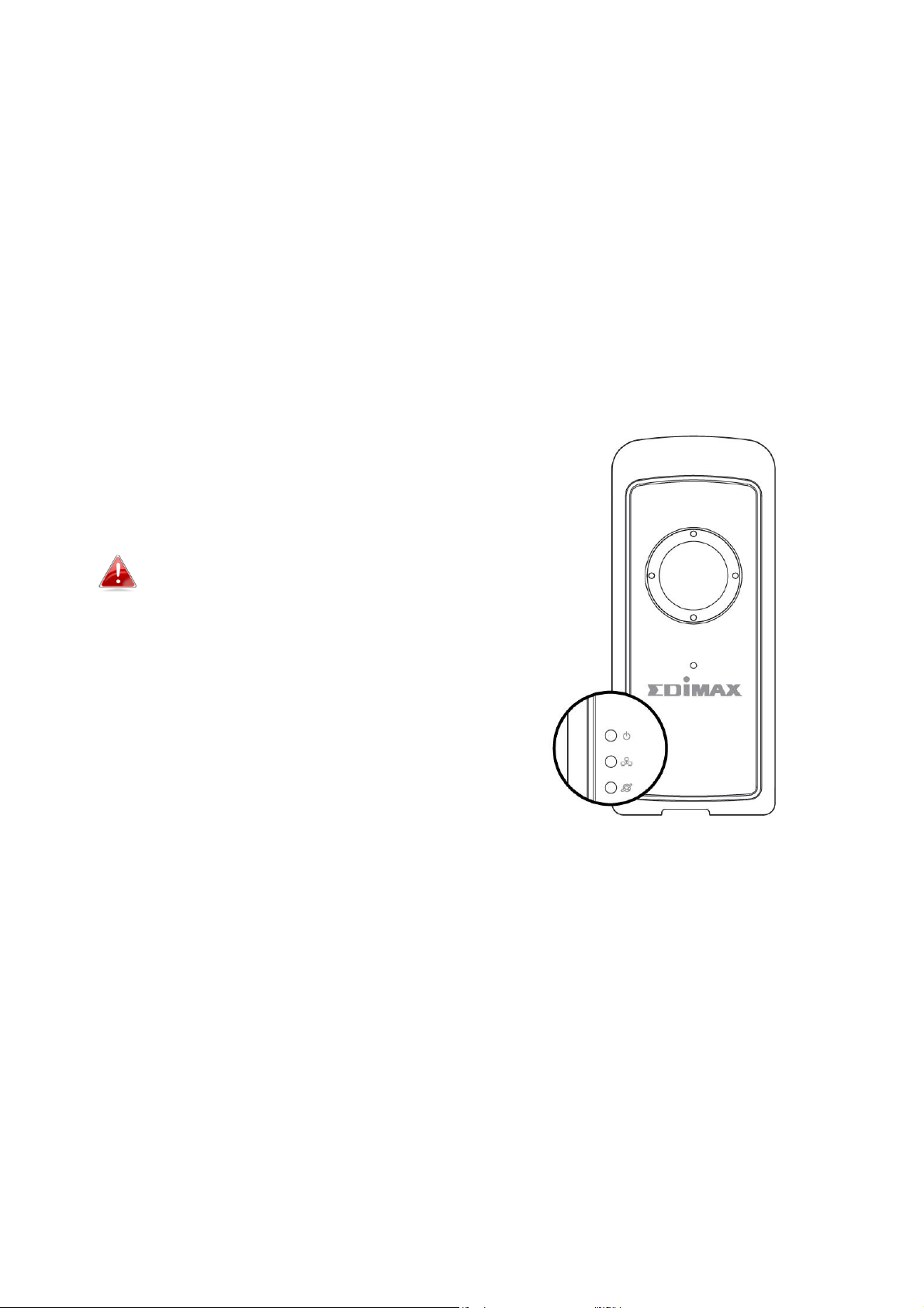
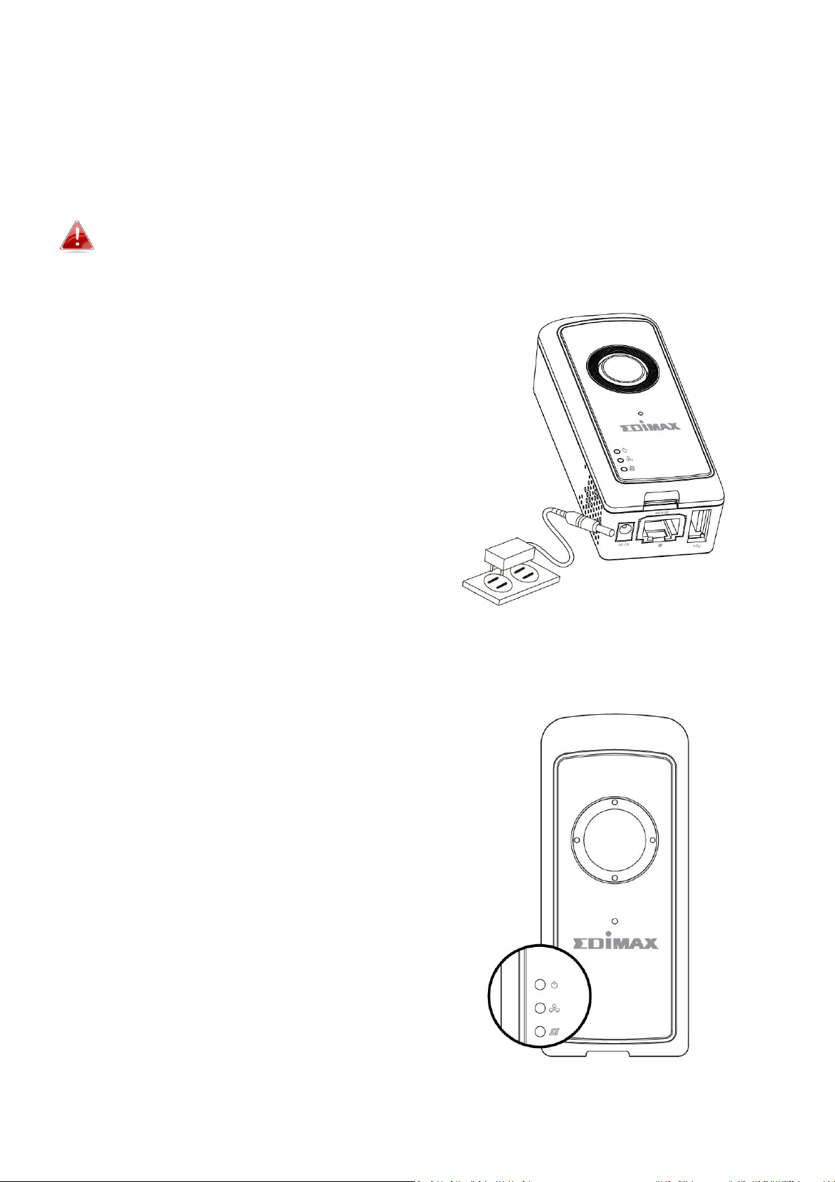
I-3. LED Status
LED
LED Color
LED Status
Description
Power
Green
On
Network camera is on and
connected to cloud server.
Quick Flashing
Network camera is restarting.
Slow Flashing (1 x
per second)
Network camera is starting up or
network camera is not connected
to cloud server.
LAN
Green
On
Network camera is connected to
the local network.
Quick Flashing
LAN activity (transferring data).
Slow Flashing (1 x
per second)
WPS is active.
Internet
Orange
On
Connected to Internet.
Slow Flashing (1 x
per second)
Not connected to Internet.
7
Page 8

I-4. Product Label
The product label located on the underside of the network camera displays
the serial number, MAC address, cloud ID and setup SSID of your network
camera.
The MAC address and cloud ID are the same for easy reference.
The cloud ID allows you to view a live stream from your network camera
remotely (from any Internet connection) as described later in V.
Myedimax.com.
8
Page 9
I-5. Reset
If you experience problems with your network camera, you can reset the
camera back to its factory default settings. This resets all settings back to
default.
1. Press and hold the WPS/Reset button found on the side panel for at least
10 seconds.
2. Release the button when the green power LED is flashing quickly.
3. Wait for the network camera to
restart. The camera is ready when the
green power LED is flashing slowly.
After setup, the green power LED
will display on to indicate a
successful connection to the cloud
server.
9
Page 10
II. Camera Setup
II-1. EdiLife App
Follow the instructions below to connect your network camera to your Wi-Fi
using the EdiLife smartphone app.
Your network camera’s unique SSID is displayed on the product label on
the network camera and consists of “EdiView.Setup **” where ** are the
last two characters of your camera’s unique MAC address.
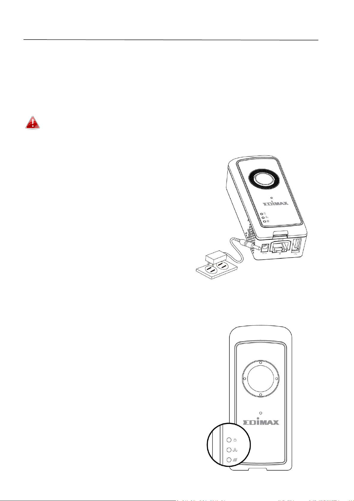
1. Connect the network camera to a
power supply using the included
power adapter.
2. Wait a moment for the camera to
power on. The green power LED will flash slowly when it’s ready.
10
Page 11
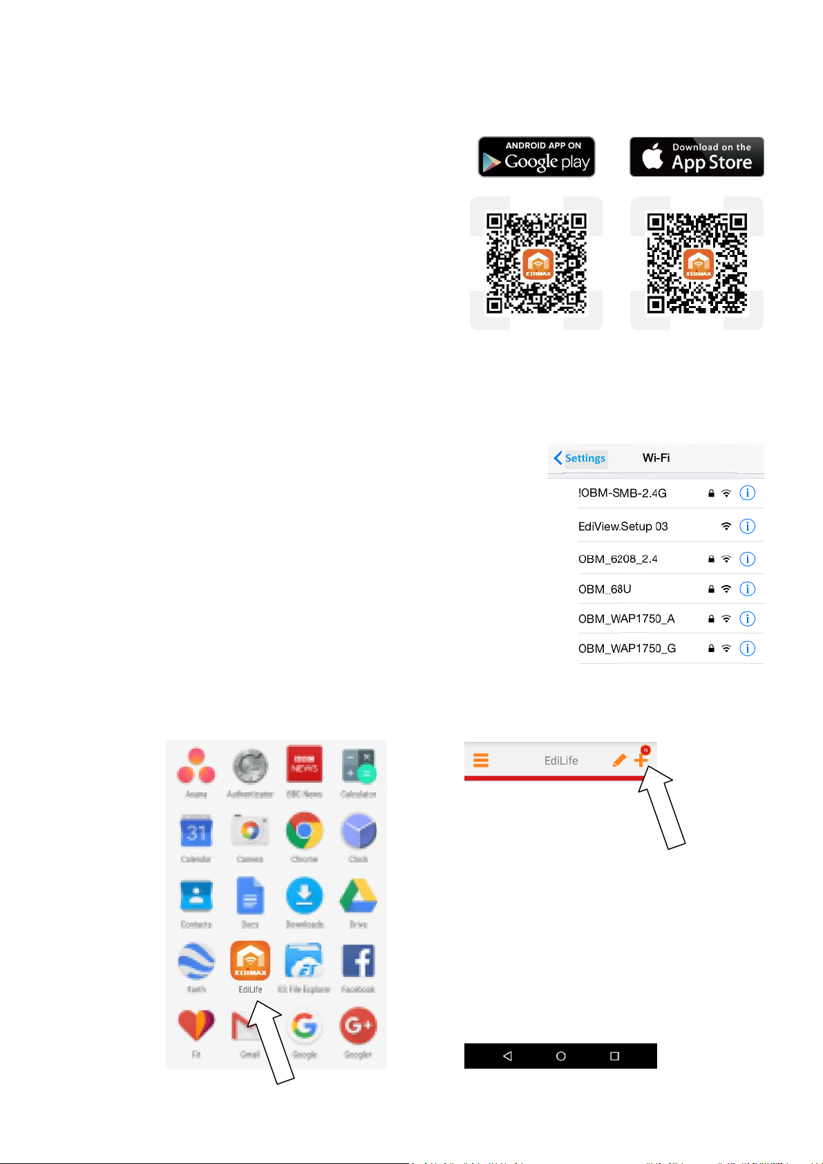
3. Use a smartphone or tablet to search, download and install the EdiLife app
from Google Play or the Apple App Store.
4. For iOS users, go to your iPhone’s Wi-Fi settings and connect to your
network camera’s SSID (EdiView.Setup **), before opening the EdiLife app.
Continue to Step 7.
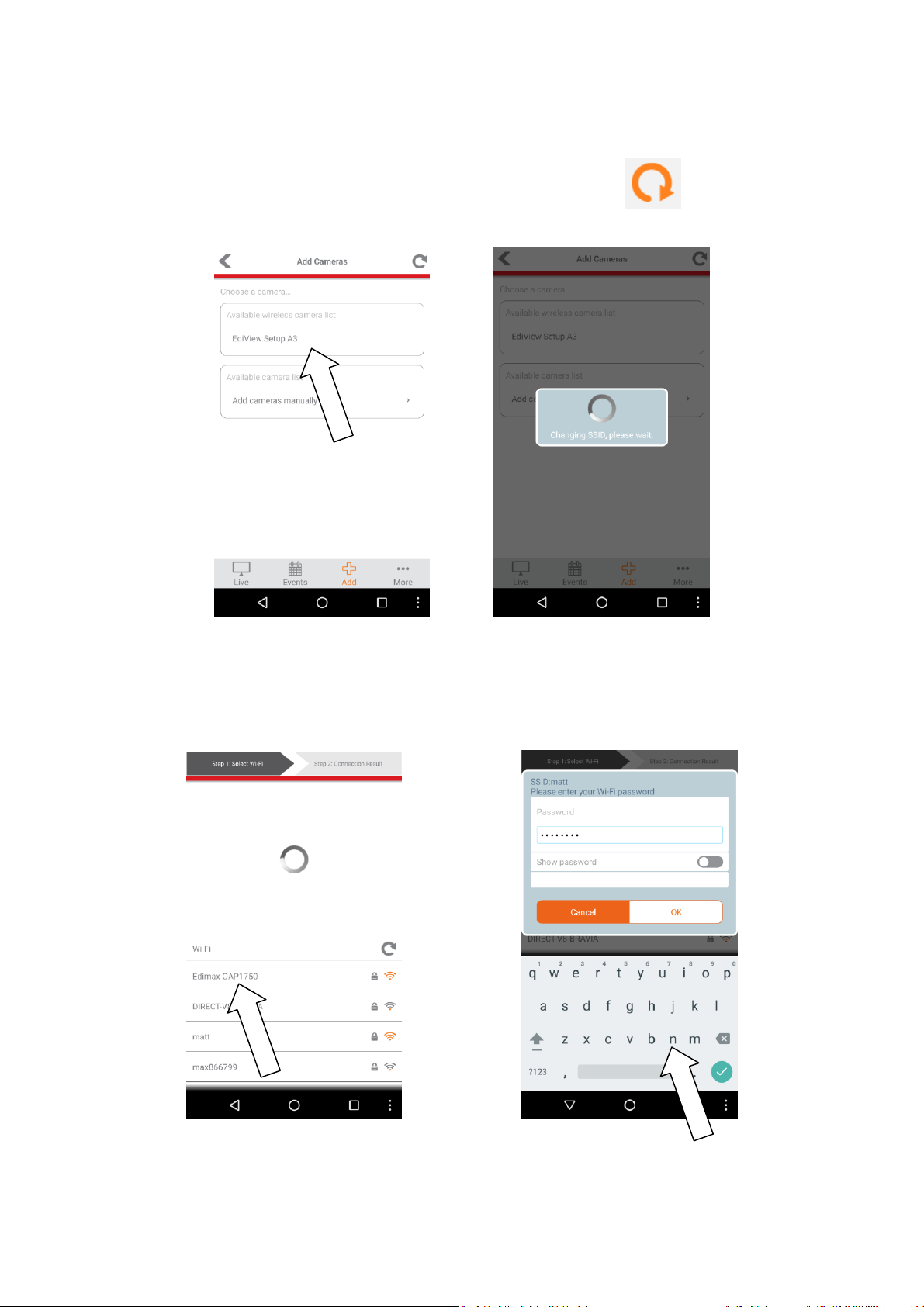
5. Android users open the EdiLife app and tap the + icon in the top-right
corner of the screen.
11
Page 12
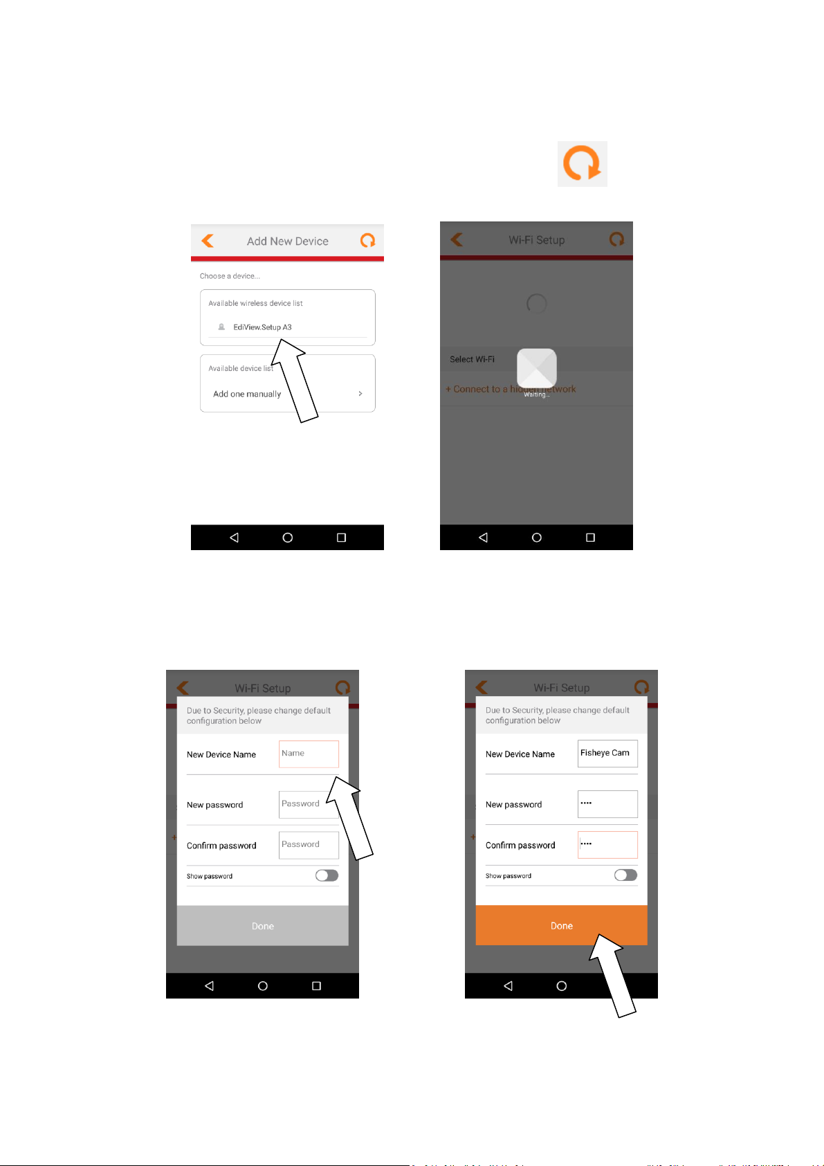
6. Android users select your camera from the available wireless device list
and wait a moment for the app to make a connection.
Tap refresh in the top right corner if your
camera isn’t listed.
7. For better security, enter a new device name and password when
prompted. Tap Done to continue.
12
Page 13
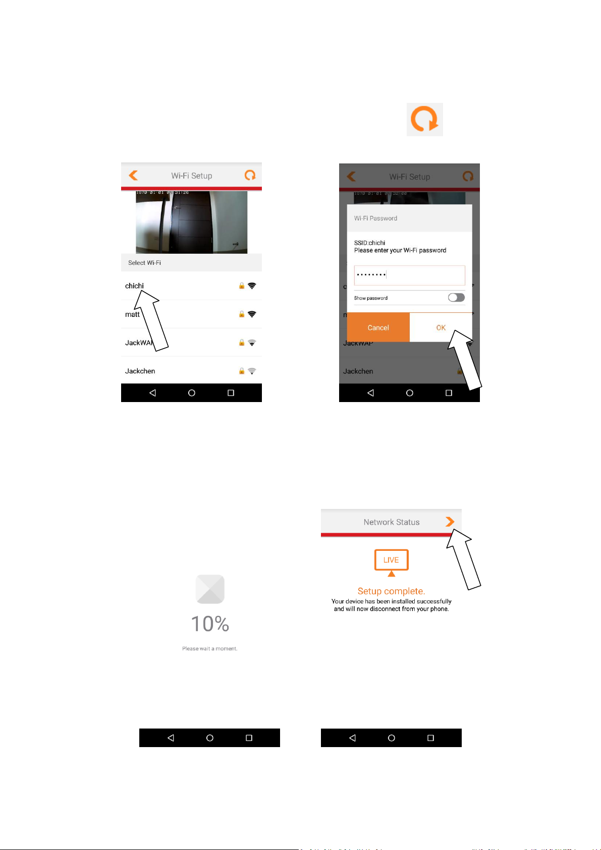
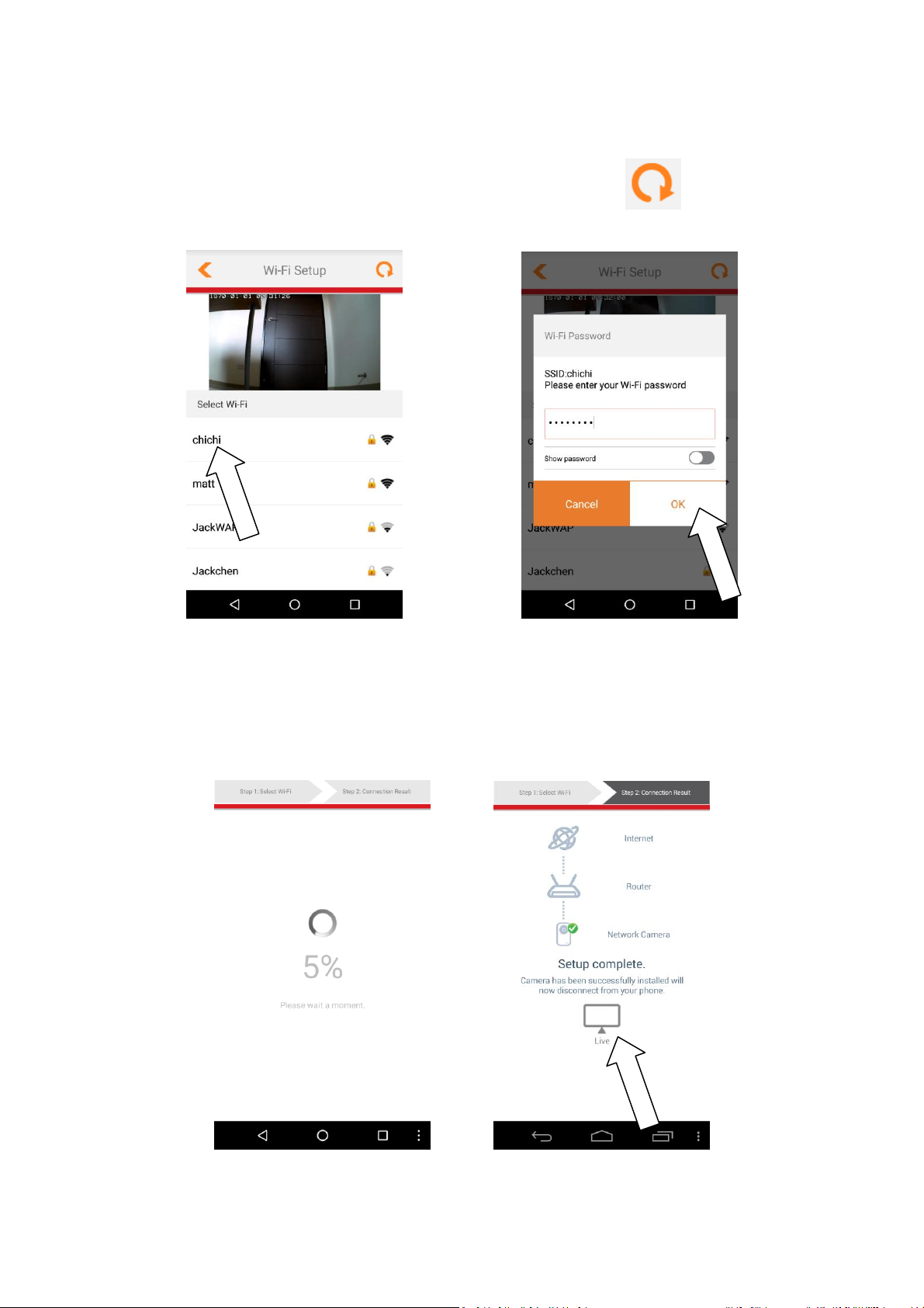
8. Select your Wi-Fi from the list and enter your Wi-Fi password. Tap OK to
continue.
Tap refresh in the top right corner if your Wi-Fi
isn’t listed.
9. Please wait a moment while your camera connects to your Wi-Fi. When
you see the Setup complete screen, click the LIVE icon or tap the arrow to
continue.
13
Page 14
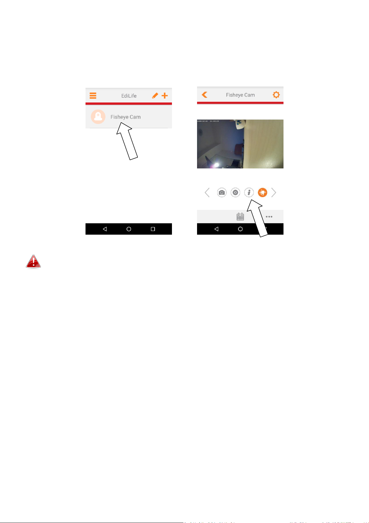
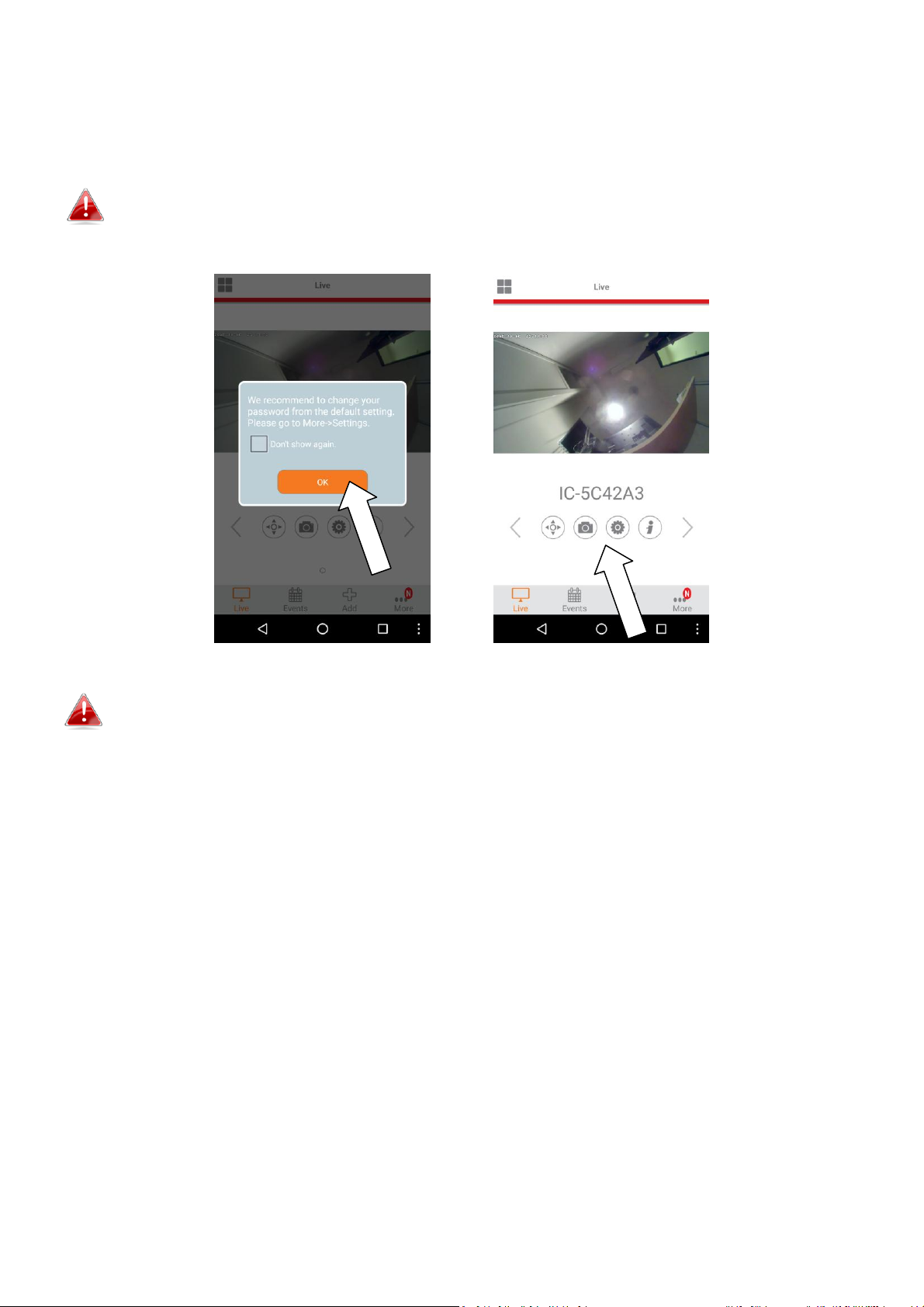
10. Setup is complete. The camera’s green power LED & orange Internet
LED should display on. Your camera should be listed on the EdiLife home
screen. Tap your camera to see a live stream which you can view anytime
you are connected to the Internet.
You can configure your camera’s settings and functions using the icons
below the live image.
11. If you have a microSD card, insert the card into the microSD slot on
the back on the network camera.
14
Page 15
II-2. EdiView II App
Follow the instructions below to connect your network camera to your Wi-Fi
using the EdiView II smartphone app.
Your network camera’s unique SSID is displayed on the product label on
the network camera and consists of “EdiView.Setup **” where ** are the
last two characters of your camera’s unique MAC address.
1. Connect the network camera to a
power supply using the included
power adapter.
2. Wait a moment for the camera to
power on. The green power LED will flash slowly when it’s ready.
15
Page 16
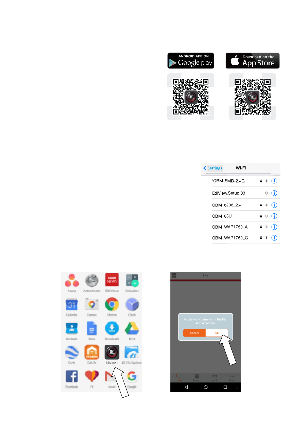
3. Use a smartphone or tablet to search, download and install the EdiView II
app from Google Play or the Apple App Store.
4. For iOS users, go to your iPhone’s Wi-Fi settings and connect to your
network camera’s SSID (EdiView.Setup **), before opening the EdiView II
app. Continue to Step 7.
5. Android users open the EdiView II app and tap OK to continue.
16
Page 17
6. Android users select your camera from the available wireless camera list
and wait a moment for the app to make a connection.
Tap refresh in the top right corner if your
camera isn’t listed.
7. Android & iOS users select your Wi-Fi network from the list and then enter
your Wi-Fi password, before clicking “OK”.
17
Page 18
8. Select your Wi-Fi from the list and enter your Wi-Fi password. Tap OK to
continue.
Tap refresh in the top right corner if your Wi-Fi
isn’t listed.
9. Please wait a moment while your camera connects to your Wi-Fi. When
you see the Setup complete screen, click the LIVE icon or wait for a
moment to continue automatically.
18
Page 19
10. Setup is complete. The camera’s green power LED & orange Internet
LED should display on. You will see a live stream which you can view
anytime you are connected to the Internet.
It is recommended that you change your camera’s password. Go to
“More” in the bottom right corner and select “Settings”.
You can configure your camera’s settings and functions using the icons
below the live image.
11. If you have a microSD card, insert the card into the microSD slot on
the back on the network camera.
19
Page 20
II-3. EdiView Finder
Ensure your computer is connected to the same router as the
network camera using an Ethernet cable.
II-3-1. Windows
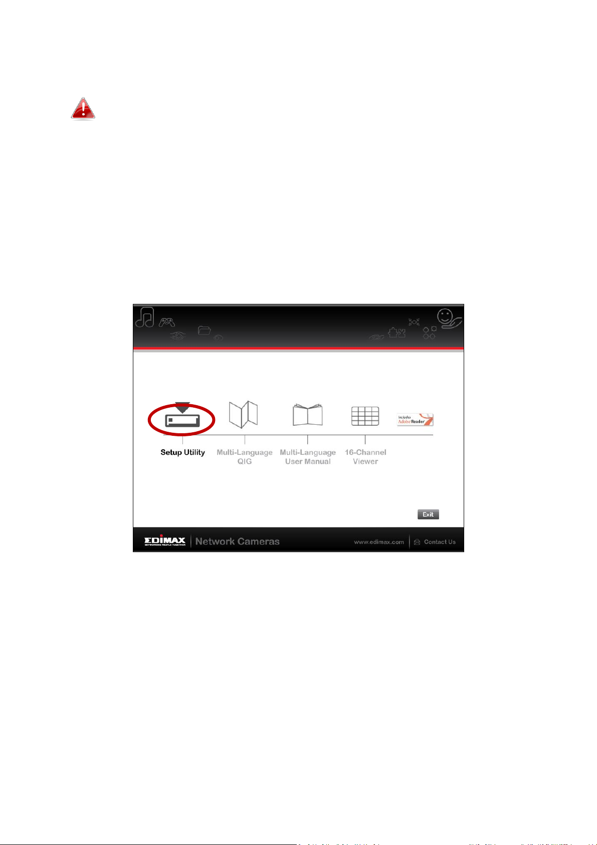
1. Insert the included CD into your CD-ROM drive and if the setup utility does
not automatically open, please locate and open the “Autorun.exe” file in
the “Autorun” folder.
2. Click “Setup Utility” to install the EdiView Finder software utility.
3. Click “Next” and follow the on-screen instructions to install the EdiView
Finder software utility.
20
Page 21
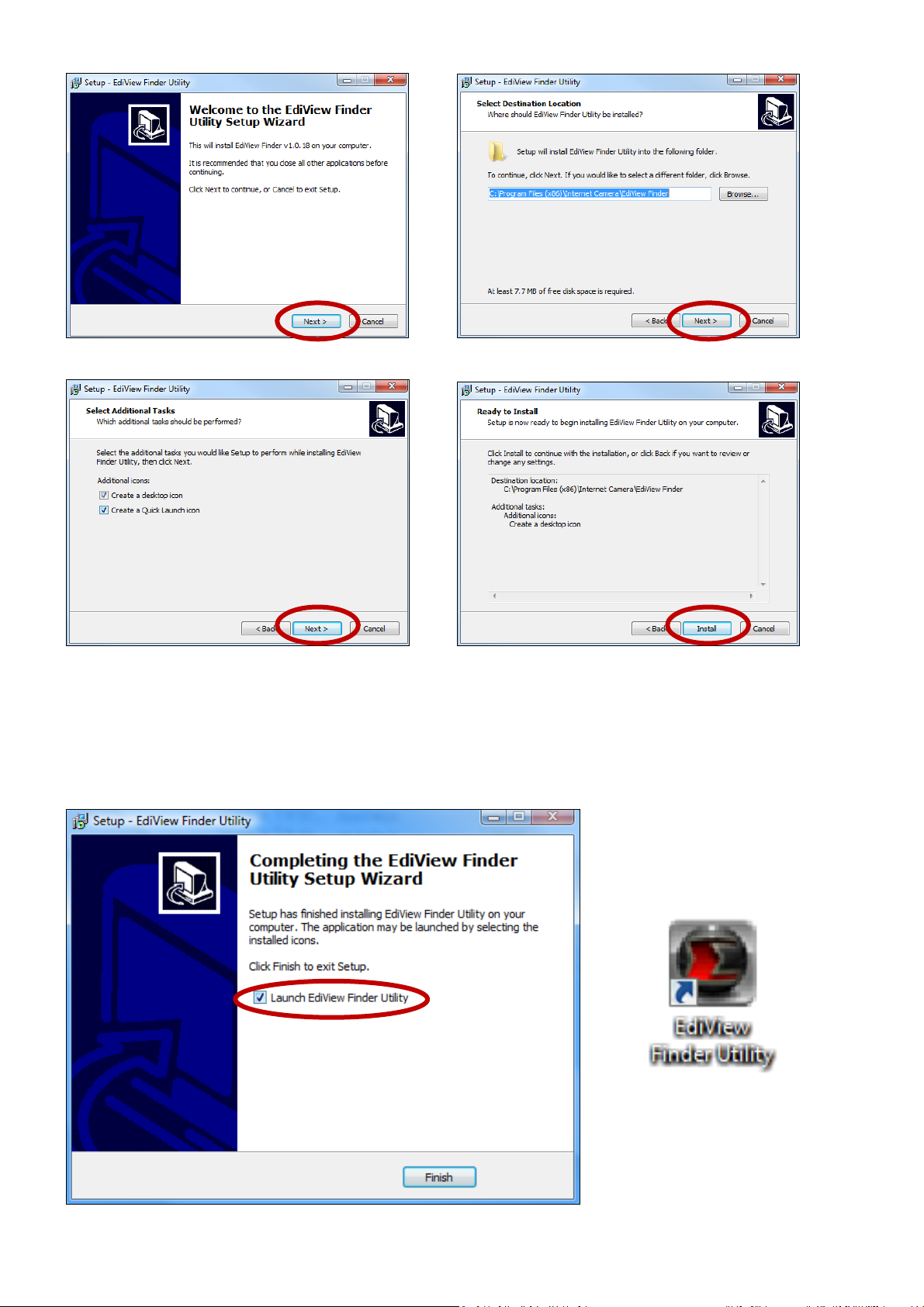
4. When installation is complete, select “Launch EdiView Finder Utility”
before clicking “Finish”. Or double click the ”EdiView Finder Utility” icon on
your desktop to launch EdiView Finder.
21
Page 22
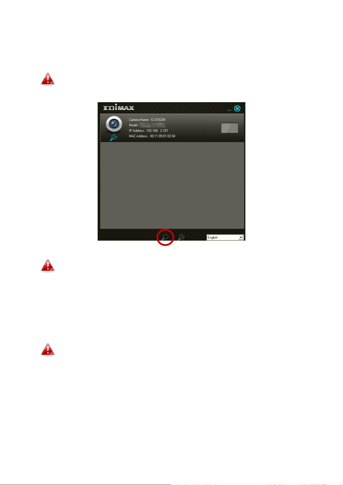
5. EdiView Finder will list all cameras on your local network, along with each
camera’s name, model, IP address and MAC address.
Click the search icon to refresh the list if your camera is not
displayed.
The network camera’s IP address is displayed on this screen. After
setup, you can enter this IP address into the URL bar of a web
browser on the same local network to access your network
camera’s web-based configuration interface.
6. Double click your camera and then choose “Yes” or “No” if you wish to set
up a wireless connection. If you choose “No” please go to step 10.
The IC-5150W is a wireless camera, you can choose “Yes” to set
up your wireless connection.
22
Page 23
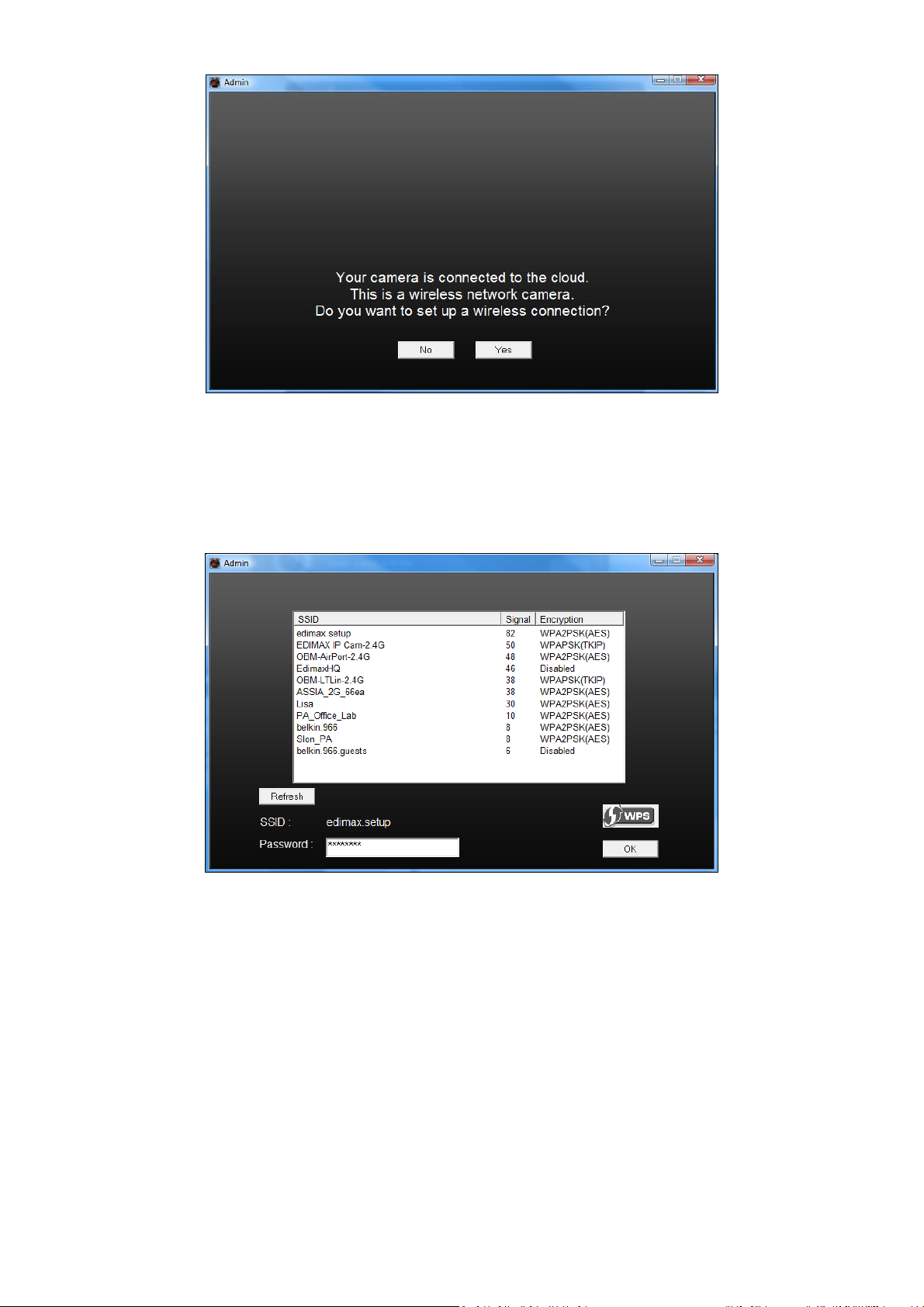
7. Select your wireless network from the list and enter the correct password
in the “Password” field, before clicking “OK”. This is the wireless network
which your camera will connect to.
8. Unplug the Ethernet cable from your network camera and click “Next”.
Please wait a moment for the camera to detect the connection.
23
Page 24
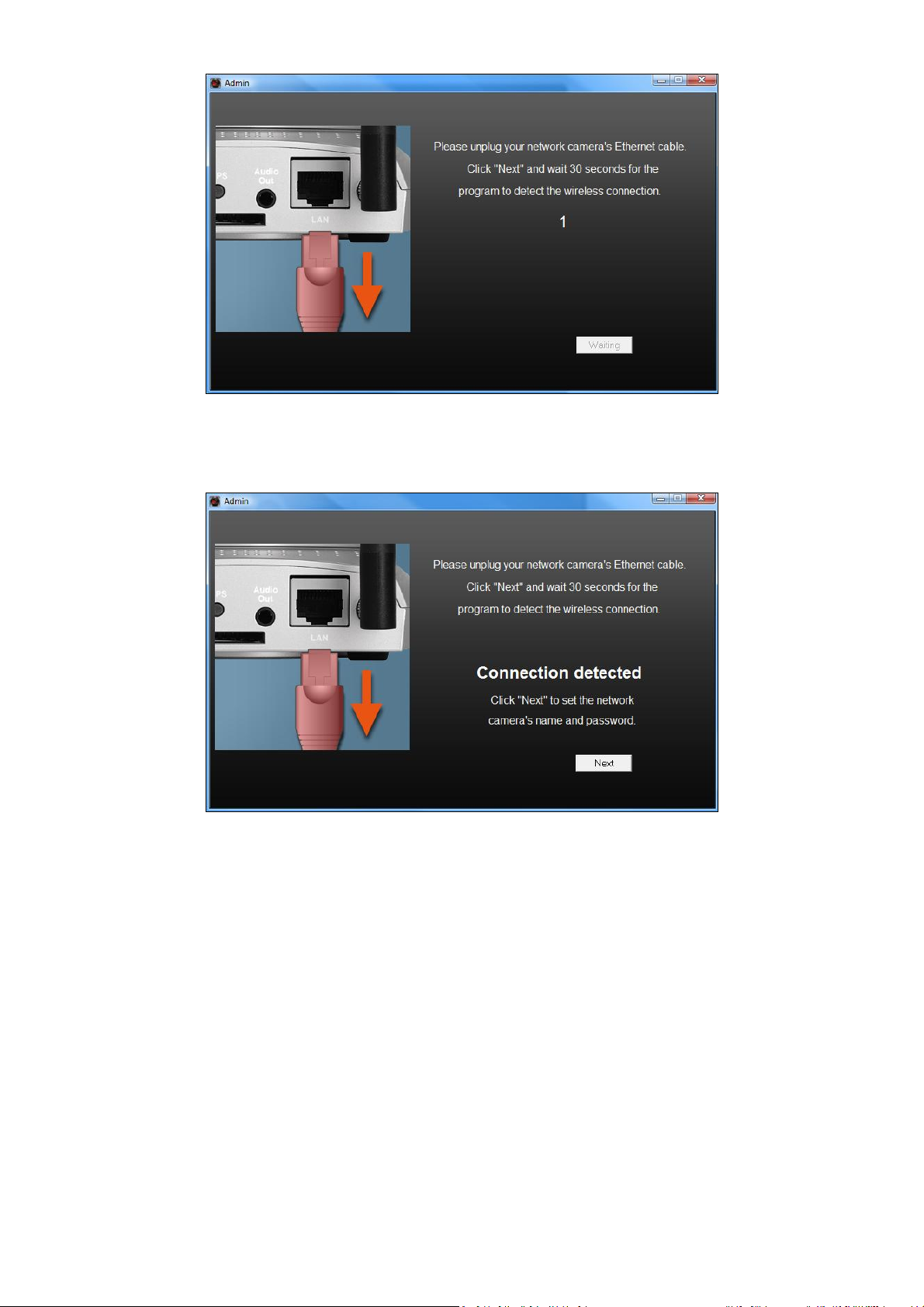
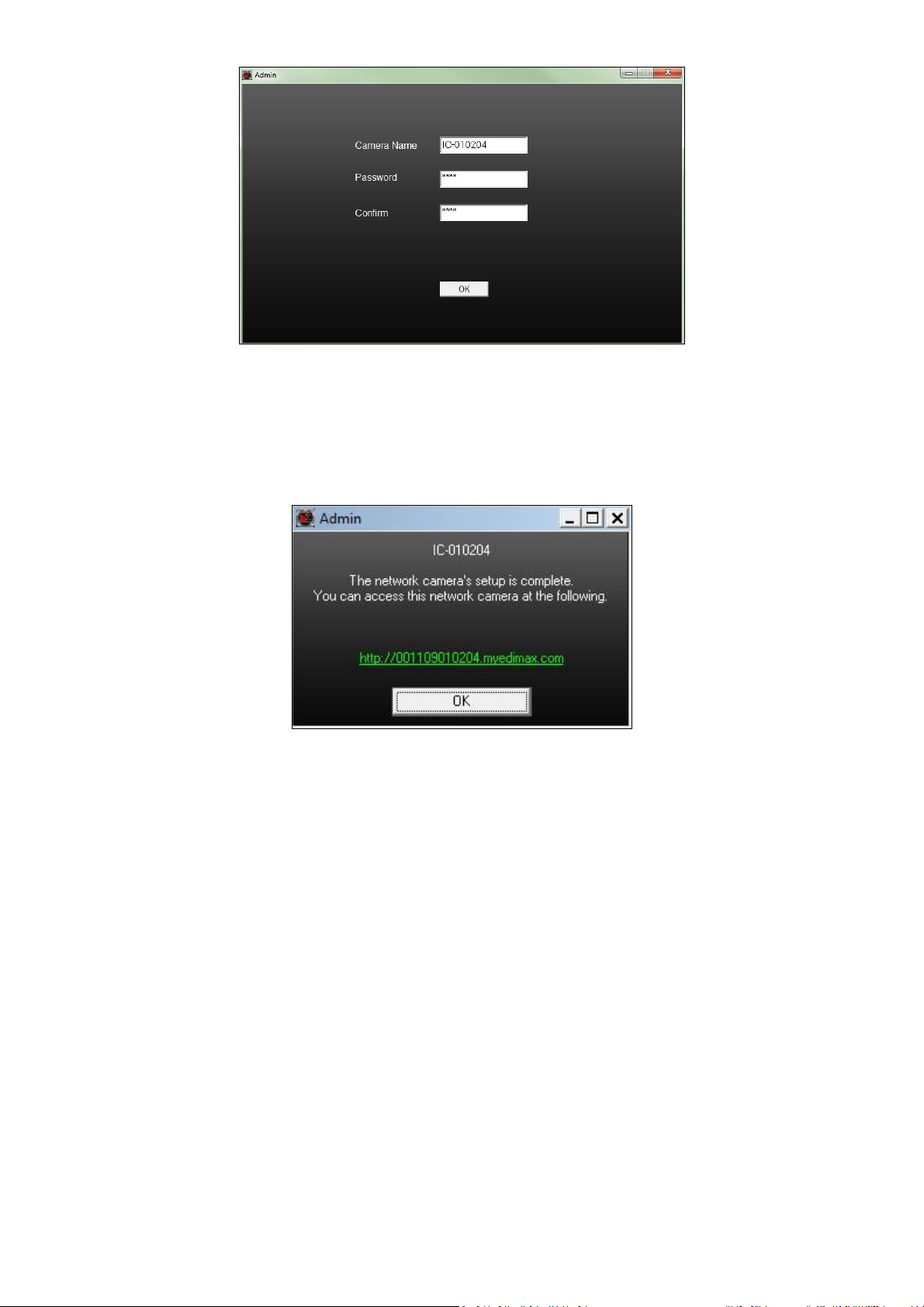
9. When the connection is detected as shown below, please click “Next”.
10. Enter a name and password for your camera. The password will be
used later to log in to your camera remotely via its cloud ID, web interface
or via the EdiView II smartphone app. Click “OK” to continue.
24
Page 25
11. The next screen will indicate that setup is complete. The camera is
operational and ready for use. Click “OK”or click the URL and a preview
window showing a live stream from your camera may open.
25
Page 26
II-3-2. Mac
EdiView Finder for Mac will not set up your network camera’s
wireless connection. After this chapter, please continue to IV-1-2.
Wireless to set up the camera’s wireless connection.
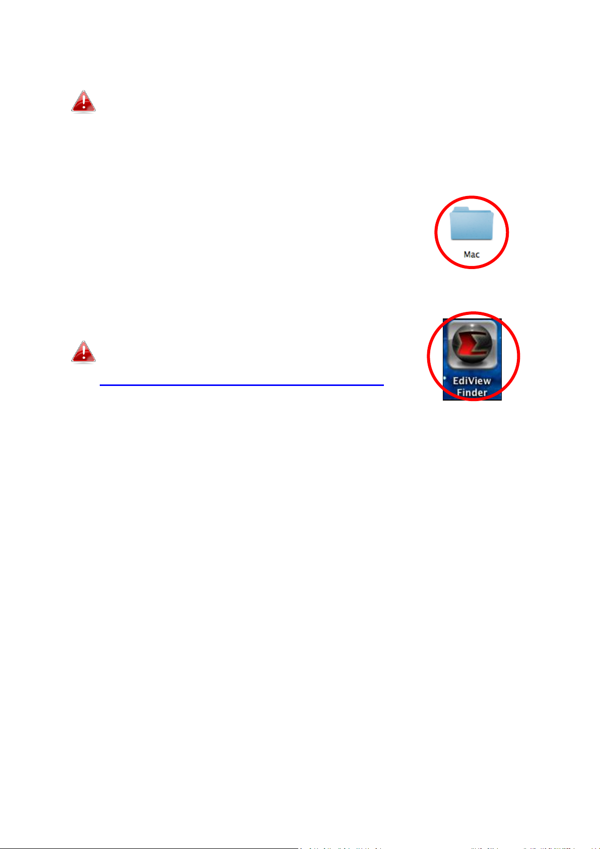
1. Insert the included CD into your CD-ROM drive and browse to the “Mac”
folder.
2. Copy the “EdiView Finder” file to your desktop and double click the icon to
open EdiView Finder.
EdiView Finder is also available for download from
the Edimax website:
http://www.edimax.com/EdiViewFinder.htm
26
Page 27
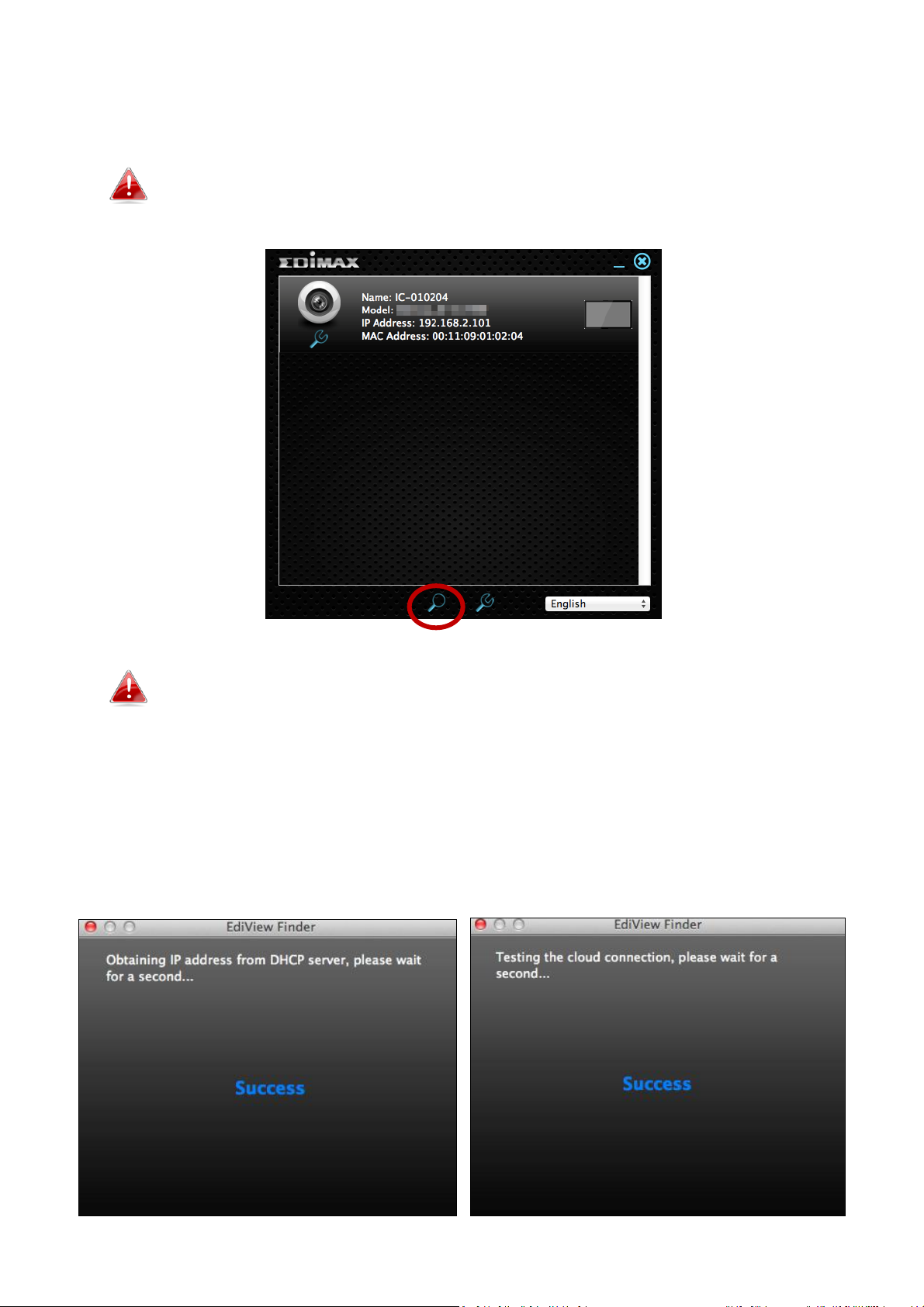
3. EdiView Finder will list all cameras on your local network, along with each
camera’s name, model, IP address and MAC address.
Click the search icon to refresh the list if your camera is not
displayed.
The network camera’s IP address is displayed on this screen. After
setup, you can enter this IP address into the URL bar of a web
browser on the same local network to access your network
camera’s web-based configuration interface.
4. Double click your network camera and wait a moment for the network
camera to obtain an IP address and test the cloud connection. EdiView
should display “Success” as shown below.
27
Page 28
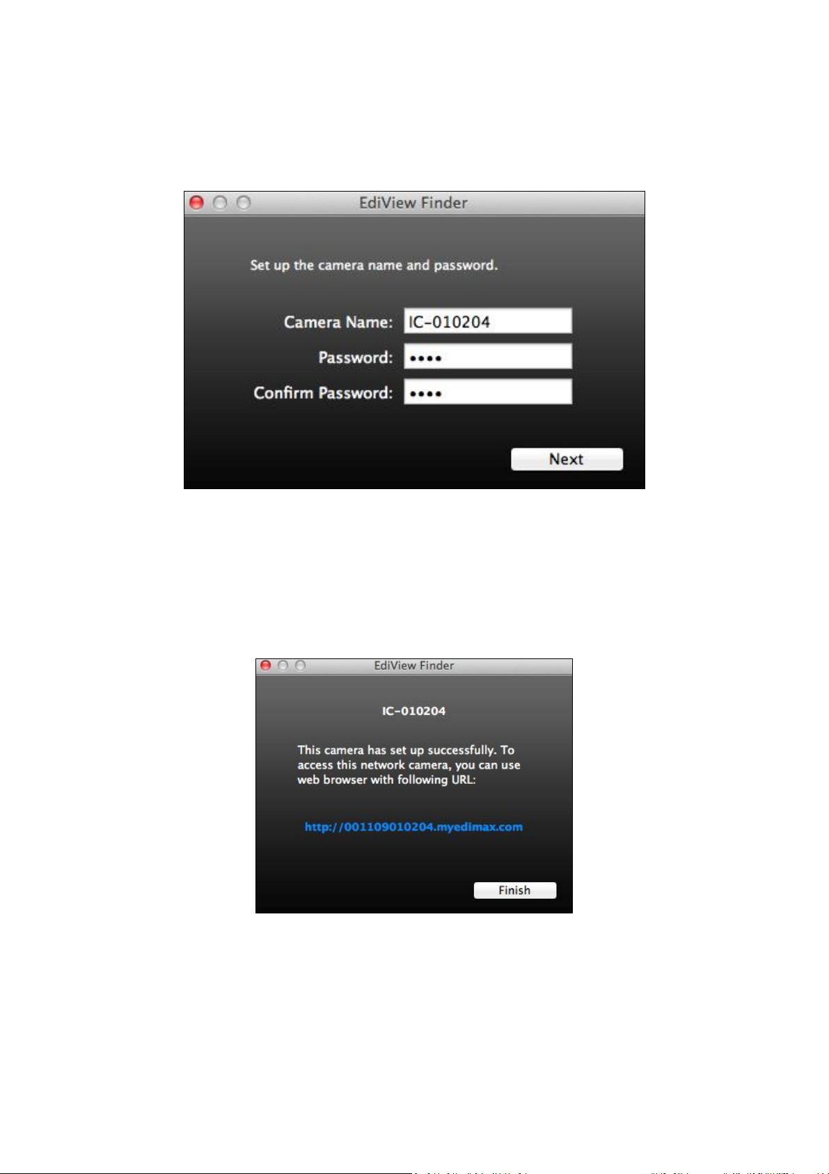
5. Enter a name and password for your camera. The password will be used
later to log in to your camera remotely via its cloud ID, web interface or via
the EdiView II smartphone app. Click “Next” to continue.
6. The next screen will indicate that setup is complete. The camera is
operational and ready to be configured for a wireless connection. Click
“Finish” and a preview window showing a live stream from your camera
may open.
7. To setup your network camera’s wireless connection, please follow IV-1-2.
Wireless.
28
Page 29
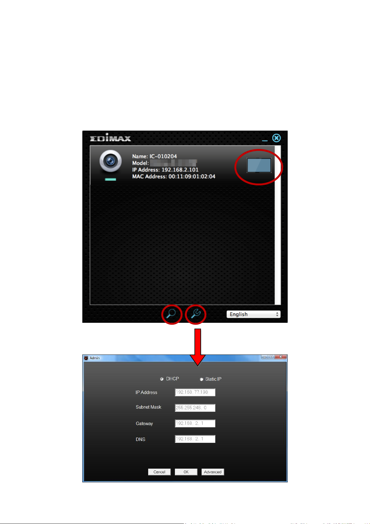
II-3-3. Using EdiView Finder
You can also use EdiView Finder to find your network camera’s IP address,
view a live stream, or modify the network camera’s IP address. Double click
the TV icon on the right side to view a live stream in a pop-up window, or click
the wrench icon to open a new window with the network camera’s IP address
settings:
29
Page 30

EdiView Finder will locate your network camera as long as you
are on the same local network. Static IP users who may be using a
different IP address subnet to the network camera should still be
able to locate the network camera with EdiView Finder. If you
encounter difficulties, it is recommended that you use a DHCP
server – though you can manually set the network camera’s IP
address using EdiView Finder (above) or using the web-based
configuration interface (see IV-1-1. Network) if you need.
30
Page 31

II-4. WPS (Wi-Fi Protected Setup)
The WPS (Wi-Fi Protected Setup) button is a quick and easy alternative to
establish a secure wireless connection between your network camera and
your wireless router/access point.
1. Press and hold the WPS button on your wireless router/access point for
the correct length of time to activate its WPS.
Please check the instructions for your
wireless router/access point for how long
you need to hold down its WPS button to
activate WPS.
2. Within two minutes, press the WPS/Reset button on the network camera
for 2 – 5 seconds to activate WPS. The green LAN LED will flash slowly to
indicate that WPS is active.
Take care not to hold the WPS/Reset button too long and reset
your network camera.
3. The devices will establish a secure
wireless connection. The green LAN
LED will flash quickly for two minutes
to indicate a successful WPS
connection.
31
Page 32

III. Wall Mount
A wall mount is included in the package contents to fix your camera to the
wall. The stand requires some assembly.
1. Attach the wall-mount to a wall using the included screws as shown below:
2. Attach the rear of the network camera to the mounting stand and tighten
into place, as shown below:
32
Page 33

IV. Web-Based Management Interface
When you are using the same local network as your camera, you can use the
web-based management interface to view or configure the camera and to use
the camera’s functions.
You can access the web-based management interface with a web browser on
a smartphone or computer. For smartphone users, the appearance of the
interface will vary slightly to that which is displayed here, though the menu
functions which are described later from IV-1. Basic onwards are the same.
1. Enter the network camera’s IP address into the URL bar of a web browser.
The camera’s IP address can be found by opening EdiView Finder, as
displayed below:
Internet Explorer is recommended.
33
Page 34

2. You may be prompted to allow a Java add-on to run. Please click the
message where it says “click here” and then click “Run Add-on”.
If any other security warnings/prompts appear, please select
“Run” or “Allow” or similar, depending on your browser.
3. Enter the username and password for your network camera (default
username: admin default password: 1234). The network camera’s web-
based management interface will then be displayed in your browser.
34
Page 35

4. For computer users, the “Live View” screen will be displayed, as shown
Snapshot
Save a snapshot (image) of the network
camera’s current view. You will be prompted
to select a location to save the image.
Record
Record video. You will be prompted to select
a location to save the recording. The icon will
display blue while recording, click the icon
again to stop recording.
Image (Full Screen)
Click the icon to display the live view in full
screen mode.
Volume
Use the drop down menu to adjust the
volume level of the camera’s sound. Click the
microphone icon to mute the sound.
below. On the live view screen you can see a live stream from your camera
and use the icons on the left side to pan, tilt and take snapshots or
recordings.
35
Page 36

When ePTZ is selected (see below), use the
icons to zoom in and out and rotate left and
right.
Remote Control
When ePTZ is selected (see below), use the
remote control to pan/tilt the camera and
adjust the viewing position.
Preset
Adjust the camera’s viewing position to any of
four preset viewing points. Presets can be
configured in Pan & Tilt Preset (refer to IV-
5-2. Preset)
Stretch
Stretch the fish eye view to a flat image.
ePTZ
Enable the electronic pan, tilt and zoom
functions and use the buttons on the left side
for control.
Fish Eye
Click the icon to display the standard fish eye
view.
Stretch Left
Display the left side of the view as the full
available image.
Stretch Right
Display the right side of the view as the full
available image.
ePTZ
Fish Eye
Stretch Right
Stretch Left
Stretch
5. Select “Setup” at the top center and use the menu down the left side to
navigate to the network camera’s various settings. Each menu item is
described in the following chapters.
36
Page 37

6. After making any changes, click “Save Settings” to save the settings and
bring the changes into effect.
37
Page 38

IV-1. Basic
The “Basic” menu opens a submenu with eight
categories of settings for your network camera’s basic
operation. Select a category and refer to the
appropriate chapter.
38
Page 39

IV-1-1. Network
Network Type
Select “DHCP” to automatically assign an IP
address to your network camera from your
router or “Static IP” to manually set a static IP
address using the fields below.
IP Address
Static IP users specify an IP address here,
which will be the IP address of your network
camera.
Subnet Mask
Enter the subnet mask of the IP address.
Gateway
Enter the gateway address of your network.
Primary DNS
Enter the IP address of your primary DNS
server.
Secondary DNS
Enter the IP address of your secondary DNS
server (optional).
HTTP Port
You can edit the HTTP port number to any
value between 1024 – 65535. The default
value is 80.
Network settings are displayed on this page, as shown below. You can
configure your network camera to dynamically receive a local IP address from
your router’s DHCP server or you can specify a local static IP address for your
network camera.
39
Page 40

IV-1-2. Wireless
The wireless page allows you to configure settings for your network camera’s
wireless connection. For Windows users, your wireless connection should
have been set up already using EdiView Finder, though you can still use this
page to revise the settings if you need.
Mac users need to configure these settings manually since EdiView Finder on
Mac will not set up your camera’s wireless connection. A quick guide to set up
your network camera’s wireless connection using a smartphone or a
computer is included below.
Mac users setting their network camera’s wireless connection for
the first time please ensure your network camera is connected to
your router/access point/switch via Ethernet cable.
You can also use the “wireless” page for Wi-Fi Protected Setup (WPS): to
either activate push-button WPS (the same effect as physically pushing the
hardware WPS button built into the camera), or PIN code WPS (using a PIN
code for verification between the two wireless devices for additional security.)
40
Page 41

IV-1-2-1. Computer
A
Wireless Connection
Select “Enable” to enable the wireless connection.
B
Available Network
Click “Refresh” to display all available Wi-Fi
networks.
C
Connected
Select your Wi-Fi network from the list. This is the
wireless network which your camera will connect to.
D
WPA Pre Shared Key
Enter your Wi-Fi password.
E
Save Settings
Click “Save Settings” to save your settings.
A
C D E
B
1. Configure the wireless settings A – E shown in the table below:
2. After the settings are saved, remove the Ethernet cable from your
network camera. Your camera should now be connected to your Wi-Fi.
41
Page 42

IV-1-2-3. WPS
Self PinCode
Your network camera’s WPS PIN code is listed
here.
Access PBC Mode
Click “Start PBC” to activate push-button WPS
on your network camera. This has the same
effect as physically pushing the built-in
hardware WPS button.
Configure via
PinCode
Enter the SSID you wish to connect to and
click “Start PIN” to activate PIN code WPS.
You will then need to enter the network
camera’s “Self PinCode” into your wireless
router’s web U.I. and activate your router’s
PIN code WPS.
WPS (Wi-Fi Protected Setup) is a quick and easy way to set up wireless
connections between compatible devices. Use the “Start PBC” or “Start PIN”
button to activate WPS on your network camera. Your network camera’s WPS
PIN code is also listed next to “Self PinCode”.
Please refer to your wireless router’s instructions for help
accessing its web-based interface and activating WPS.
42
Page 43

IV-1-3. Dynamic DNS
Enable DDNS
Select “Enable” to enable DDNS functionality,
or select “Disable” to disable DDNS
functionality.
Provider
Select your dynamic DNS service provider
from the dropdown menu.
Host Name
Enter the hostname you registered with the
DDNS service provider.
User Name
Enter the user name you registered with the
DDNS service provider.
Password
Enter the password you registered with the
DDNS service provider.
Dynamic DNS (DDNS) is a service which provides a hostname-to-IP service for
dynamic IP users. If your Internet service provider didn’t issue a fixed IP
address, you can use a third-party dynamic DNS provider to map your current
IP address to a fixed IP address. Several free or paid DDNS services are
available online, please use the information provided by your DDNS provider
to configure the settings on this page.
43
Page 44

IV-1-4. RTSP
RTSP Port
Enter the RTSP port.
H.264 RTSP Path
(HD)
Enter the H.264 RTSP path.
H.264 RTSP Path
(Mobile)
Enter the H.264 Mobile RTSP path.
RTP Port Range
Enter the RTP port range.
Verification
Select a verification type from the drop down
menu.
Real Time Streaming Protocol (RTSP) enables the network camera to be used
with a streaming media server. Enter the required RTSP settings.
44
Page 45

IV-1-5. Date & Time
Mode
Select ”NTP” or “Manual Setting”. NTP
(Network Time Protocol) can set and maintain
the time and date automatically via an NTP
server on the local network, if available.
Set Time & Date
Manually
For manual setting mode, enter the correct
time and date in the following format:
YYYY/MM/DD HH:MM:SS
Synchronize to PC
time
Click here to automatically enter the same
time and date as your computer.
NTP Server
For NTP mode, enter the NTP server’s
hostname or IP address.
Time Zone
Select the correct time zone.
Daylight Saving
Enable or disable daylight saving according
your local time zone.
You can set and adjust the network camera’s system time and date on this
page. Maintaining a correct system time is particularly important for recorded
video organization/playback.
45
Page 46

IV-1-6. Users
User List
Existing users are listed here. Select a user
here to modify the settings.
User Name
Input user’s name here.
Password
Input user’s password here.
Confirm password
Input user’s password here again for
confirmation.
In addition to the default administrator account, you can configure several
different login accounts for the network camera, with two different levels of
access – operator and guest.
Operator accounts can configure partial functions of the network camera
similar to the administrator account, while guest accounts can only view the
camera’s image.
46
Page 47

Authority
Select the user’s authority:
Operators can view video and configure some
settings, while guests can only view video.
Add
Add a new user.
Modify
Save the changes to an existing, selected user.
Remove
Remove selected user.
Anonymous Login
Enable or disable anonymous login.
Anonymous login allows anyone to login to
the network camera and view images. This
function is useful if you want to setup a
remote video server.
47
Page 48

IV-1-7. UPnP
Enable/Disable
Enable or disable UPnP.
IGD Enable (UPnP
Port Forward)
Enable or disable Internet Gateway Device
(IGD).
IGD Configuration
(External Port)
Select fully-automated or semi-automated
IGD.
External HTTP Port
Enter an external HTTP port.
External RTSP Port
Enter an external RTSP port.
Universal plug-and-play (UPnP) is a set of networking protocols which enables
network devices to communicate and automatically establish working
configurations with each other. When enabled, Windows computers can
automatically discover the network camera on the local area network. The
network camera also supports IGD.
48
Page 49

IV-1-8. Bonjour
Bonjour is a feature of Mac computers which allows Safari web browser to
discover devices and services on the local network and provide a quick
shortcut for access. When enabled, Safari users on the local network can find
a shortcut to the network camera under Safari’s “Bonjour” menu. Select
“Enable” or “Disable”.
49
Page 50

IV-2. Video
The “Video” menu consists of three categories for
configuring the network camera’s video settings.
Select an item from the submenu and refer to the
appropriate following chapter.
50
Page 51

IV-2-1. Video Settings
H264
H264 Resolution
Select a H264 video resolution from the
dropdown menu. A higher resolution provides
more detailed video but requires more
bandwidth.
Maximum Frame
rate
Select the maximum video frame rate. A
higher frame rate provides smoother video,
but also requires more bandwidth.
H264 Maximum Bit
Rate
Select a maximum bit rate for H264 videos
from the dropdown menu. A higher bit rate
provides more detailed video but requires
more bandwidth. The bit rate is accurate
±20%.
MJPEG
MJPEG Resolution
Select a MJPEG video resolution from the
dropdown menu. A higher resolution provides
The “Video Settings” page enables you to modify the network camera’s
resolution and frame rate settings for different formats: H264 & MJPEG, as
well as configure specific settings for smartphone viewing.
51
Page 52

more detailed video but requires more
bandwidth.
Maximum Frame
rate
Select the maximum video frame rate. A
higher frame rate provides smoother video,
but also requires more bandwidth.
MJPEG Quality
Select a quality level for MJPEG videos from
the drop down menu. Higher quality requires
more bandwidth.
For Smartphone
H264 Resolution
Select a H264 video resolution from the
dropdown menu. A higher resolution provides
more detailed video but requires more
bandwidth.
Maximum Frame
rate
Select the maximum video frame rate. A
higher frame rate provides smoother video,
but also requires more bandwidth.
H264 Maximum Bit
Rate
Select a maximum bit rate for H264 videos
from the dropdown menu. A higher bit rate
provides more detailed video but requires
more bandwidth. The bit rate is accurate
±20%.
Power frequency
Adjust the power frequency to 50 Hz or 60 Hz
frequency depending on your local region, in
order to reduce flicker/improve playback in
your videos.
Rotate Image
Rotate the camera’s image by the specified
angle.
OSD
Set the network camera’s on-screen display
(OSD) consisting of time & date to on or off
for all live video and video recordings.
52
Page 53

IV-2-2. Image Appearance
Brightness/
Contrast/
Saturation/
Sharpness/
Click and drag the blue lever to change the
value according to your preference for each
category.
Reset to default
Click to reset all settings back to the default
value of 50.
Save value
Save changes.
The “Image Appearance” page allows you to adjust various parameters
relating to the network camera’s image appearance using the sliders shown
below.
53
Page 54

IV-2-3. Privacy Protector
Privacy Protector is a function which will display the camera’s live view as a
black screen. This can be a useful tool when occupants are at home to address
privacy concerns about network intruders.
54
Page 55

IV-3. Events
Select an item from the “Events” menu and refer to
the appropriate following chapter. You can configure
settings for motion detection, scheduling, SMTP and
FTP.
IV-3-1. Motion Detection
IV-3-1-1. Motion Detection
The network camera features a motion detection function and various options
for (motion detection) events notification. When motion is detected, it is
defined as an “event” and the camera will record for a specified length of time.
You can set the camera to send this recording as a notification via email or
FTP, and/or to local storage such as a NAS or microSD card inside the camera.
You can also set the camera to send a push notification for each event to a
smartphone with EdiView II or EdiLife installed. You can view a 10 second
recording of the event, which is automatically stored in the network camera’s
memory, from the app’s “Events” menu.
Recordings stored automatically in the network camera are
limited to 10 seconds and only a limited quantity can be stored.
These recordings are separate from any recordings saved to local
storage or sent via email/FTP, and will be overwritten as new
recordings are created.
55
Page 56

Motion Detection
Enable or disable the motion detection
function of your network camera.
Interval Time To
Detect
After motion is detected, the network camera
will not detect motion again for this length of
time. For example, using an “Interval Time To
Detect” of 20 seconds means that after
motion is detected, the camera will not
detect any further motion for 20 seconds.
Then after 20 seconds, the camera will detect
motion again.
Upload Event File to
FTP
A video recording of a detected event can be
sent to a designated FTP server. Select
“Enable” or “Disable” for this function. When
enabled, you need to configure the FTP server
information on the “FTP” page of the “Events
Notification” menu.
Send Event File to
Email
A video recording of a detected event can be
sent to a designated email recipient. Select
56
Page 57

“Enable” or “Disable” for this function. When
enabled, you need to configure email settings
in the “Events Notifications Mail
Settings” menu.
Video Recording
Time
Specify the length of time for the email or FTP
video recording here.
Save Event Files to
NAS or SD
Enable or disable the camera’s function to
save video files to NAS or MicroSD card.
When enabled, you need to configure the
settings in the “Storage Settings” menu.
Video Recording
Time
Specify the length of time for the NAS or
microSD video recording here.
57
Page 58

IV-3-1-2. Detection Region
Region 1 /
Region 2 /
Region 3
Check the box to enable up to three motion
detection regions. A color-coded rectangle
will appear on the video view for each
enabled region. Adjust the size and position
of each box according to your preference by
clicking and dragging inside the box (move) or
on the edges (resize).
When using the network camera’s motion detection function, you can specify
the areas in the video where the network camera should be sensitive to
motion. Motion outside of the detection regions will be ignored by the
network camera. This is useful to avoid false alarms.
58
Page 59

Sensitivity
Adjust the sensitivity level of motion
detection for each region. A higher value will
trigger the alarm for minor motion in the
video and vice-versa. You can reduce the
sensitivity level if you receive unnecessary
event notifications.
Threshold
Adjust the motion detection threshold level
for each region. A higher value will trigger the
alarm for large objects in the video, a lower
value will trigger the alarm for smaller
objects.
Save
Save your settings.
59
Page 60

IV-3-1-3. Schedule Settings
The network camera’s motion detection function can be scheduled to be
active on/at specified times and days. Select “Enable” to enable this feature
and then define which times the network camera’s motion detection will be
active using the table below.
For each day, click and drag across the timeline on the times which you want
motion detection to be active. A blue box indicates a scheduled recording. In
the example below, motion detection is scheduled for 8am – 6pm Monday to
Saturday.
By default, the schedule may be full. Delete existing entries if
necessary. For scheduled recording, see Storage Settings
Schedule Settings.
60
Page 61

Delete
Delete the selected blue recording block on
the timeline.
Delete All
Delete all blue recording blocks on the
timeline.
Select All
Select all blue recording blocks.
Store
Store the recording settings on the timeline.
61
Page 62

IV-3-2. Sound Detection
IV-3-2-1. Sound Detection
The network camera features a sound detection function and various options
for (sound detection) events notification. When sound is detected, it is
defined as an “event” and the camera will record for a specified length of time.
You can set the camera to send this recording as a notification via email or
FTP, and/or to local storage such as a NAS or microSD card inside the camera.
You can also set the camera to send a push notification for each event to a
smartphone with EdiView II or EdiLife installed. You can view a 10 second
recording of the event, which is automatically stored in the network camera’s
memory, from the app’s “Events” menu.
Recordings stored automatically in the network camera are
limited to 10 seconds and only a limited quantity can be stored.
These recordings are separate from any recordings saved to local
storage or sent via email/FTP, and will be overwritten as new
recordings are created.
62
Page 63

63
Page 64

Sound Detection
Enable or disable the sound detection
function of your network camera.
Interval Time To
Detect
After sound is detected, the network camera
will not detect sound again for this length of
time. For example, using an “Interval Time To
Detect” of 20 seconds means that after sound
is detected, the camera will not detect any
further sound for 20 seconds. Then after 20
seconds, the camera will detect sound again.
Upload Event File to
FTP
A video recording of a detected event can be
sent to a designated FTP server. Select
“Enable” or “Disable” for this function. When
enabled, you need to configure the FTP server
information on the “FTP” page of the “Events
Notification” menu.
Send Event File to
Email
A video recording of a detected event can be
sent to a designated email recipient. Select
“Enable” or “Disable” for this function. When
enabled, you need to configure the SMTP
server information on the “SMTP” page of the
“Events Notification” menu.
Video Recording
Time
Specify the length of time for the email or FTP
video recording here.
Save Event Files to
NAS or SD
Enable or disable the camera’s function to
save video files to NAS or MicroSD card.
When enabled, you need to configure the
settings in the “Storage Settings” menu.
Video Recording
Time
Specify the length of time for the NAS or
microSD video recording here.
Sound Level
Set the level of sound which will trigger a
detection event. Adjust the slider up/down to
your preferred sound level. The vertical
display to the left of the slider indicates the
current sound level picked up by the camera’s
built-in microphone.
64
Page 65

IV-3-2-2. Schedule Settings
The network camera’s sound detection function can be scheduled to be active
on/at specified times and days. Select “Enable” to enable this feature and
then define which times the network camera’s motion detection will be active
using the table below.
For each day, click and drag across the timeline on the times which you want
motion detection to be active. A blue box indicates a scheduled recording. In
the example below, motion detection is scheduled for 8am – 6pm Monday to
Saturday.
By default, the schedule may be full. Delete existing entries if
necessary. For scheduled recording, see Storage Settings
Schedule Settings.
65
Page 66

Delete
Delete the selected blue recording block on
the timeline.
Delete All
Delete all blue recording blocks on the
timeline.
Select All
Select all blue recording blocks.
Store
Store the recording settings on the timeline.
66
Page 67

IV-3-3. Notification
Email Service
Provider
Select “Manual Settings” to enter the
information manually or select a common
email provider to enter some of the
information automatically.
SMTP Server
Input the host name or IP address of the
SMTP server for the email sender. This
information can be provided by your email
service provider.
SMTP Port
Input the SMTP port number for the email
sender. Most SMTP servers use port number
25, while some SMTP servers use encrypted
connections with a port number of 465. This
information can be provided by your email
IV-3-3-1. Mail Settings
Recordings of events (motion or sound detected) can be sent to a designated
email recipient. This function must be enabled in “Motion Detection” or
“Sound Detection” settings in the “Events” menu. Enter the required
information about your sender and recipient email accounts as shown below.
67
Page 68

service provider.
Recipient E-Mail
Address
Enter the email recipient’s email address
here.
Sender E-Mail
Address
Enter the sender’s email address here to
avoid spam filter issues.
SSL/TLS
Select ‘SSL or TLS’ when your SMTP server
requires encryption.
Consult your mail server administrator when
in doubt.
SMTP
Authentication
Select ‘Enable’ when your SMTP server
requires authentication. This information can
be provided by your email service provider.
Account
Input the SMTP account name when your
SMTP server requires authentication. This
information can be provided by your email
service provider.
Password
Input the password used for SMTP server
authentication.
Send Test Email
Click here to send a test email with the
current settings.
Gmail users please ensure that “Less Secure Apps” is enabled in
your Google account “Security” settings, otherwise your email
password may be rejected.
68
Page 69

IV-3-3-2. FTP
FTP Server
Enter the IP address or host name of the FTP
server.
User Name
Enter the user name required by the FTP
server.
Password
Enter the password of the FTP server.
Port
Enter the port number of the FTP server. This
value should be an integer between 1 and
65535. Please don’t change this value unless
advised by the FTP server’s administrator.
Path
Enter a path (folder) to save files on the FTP
server. If blank, files will be saved in the FTP
server’s default root folder.
Passive mode
Enable or disable passive mode according to
your FTP server.
Recordings of events (motion or sound detected) can be sent to a designated
FTP server. This function must be enabled in “Motion Detection” or “Sound
Detection” settings in the “Events” menu. Enter the required information
about your FTP server as shown below.
69
Page 70

IV-4-3-3. Push
Push notification
Enable or disable all push notifications.
Sound alert
Switch push notifications for sound alerts on
or off.
Video/Human
motion alert
Switch push notifications for motion
detection events on or off.
Reconnected to
Internet alert
Switch push notifications for Internet
reconnection on or off.
The network camera can send push notifications to your smartphone if you
have the EdiView II or EdiLife app installed. Push notifications can be sent
based on motion detection and sound detection events, and also when your
camera reconnects to the Internet after a disconnection.
Reconnection alerts are sent when the camera actually
reconnects to the Internet, not when a disconnection occurs.
70
Page 71

IV-4. Storage Settings
The “Storage Settings” menu enables you to
configure the settings for local storage of motion or
sound detection events/recordings. You can also
configure scheduled recording.
IV-4-1. Storage Directory
The network camera can store recordings of motion detection events to local
storage: NAS or MicroSD. Select your storage location and click “Save settings”.
A MicroSD card must be installed in the network camera to use
this function.
Configure the settings for your NAS or MicroSD card in the “NAS
Settings” or “SD Card Settings” menu respectively.
71
Page 72

IV-4-2. Schedule Settings
The network camera can be scheduled to record automatically at/on specified
times and days. Select “Enable” to enable this feature and then define at
which times the network camera will record using the table below.
For each day, click and drag across the timeline on the times which you want
to record. A blue box indicates a scheduled recording. In the example below,
recording is scheduled for 8am – 6pm Monday to Saturday.
By default, the schedule may be full. Delete existing entries if
necessary.
To set the limit for individual file sizes for scheduled recording, go
to Storage Settings NAS Settings or SD Card Settings depending
on your storage location.
72
Page 73

IV-4-3. NAS Settings
Status
Displays the status (connected or
disconnected) of your network camera and
NAS server.
NAS IP & Sharing
Resource
Enter the local IP address of your NAS and the
path of a shared folder to store your network
camera’s recordings.
Notification for
space full
Enable or disable email notifications when
your storage space is full.
Cycle Recording
(Schedule &
Manual) (Event)
Enable or disable cycle recording for either
scheduled or manual recording, or event
recording. When enabled, cycle recording will
overwrite the earliest recordings when the
storage space becomes full. When disabled,
recording will stop when storage is full.
Max Recording File
Time
Set the maximum recording time for each file.
This applies to scheduled recordings only. For
motion or sound detection recording file
times, refer to “Events Motion/Sound
Detection”.
Authentication
Select “Account” and enter the username and
If using a NAS server for local storage, configure the settings on this page
according to your NAS.
73
Page 74

password in the fields below if your NAS
server requires authentication. Select
“Anonymous” if no authentication is required.
Username
Enter the username if “Account” is selected
above.
Password
Enter the password if “Account” is selected
above.
Status
Displays the MicroSD card status of your
network camera: available or unavailable.
Available Space
Displays the available space on the MicroSD
card in your network camera.
Notify when space is
not enough
Enable or disable email notifications when
your storage space is full.
Cycle Recording
(Schedule &
Manual) (Event)
Enable or disable cycle recording for
scheduled & manual or event recording.
When enabled, cycle recording will overwrite
the earliest recordings when the storage
space becomes full. When disabled, recording
IV-4-4. SD Card Settings
Unmount your MicroSD card using the “Unmount” button before
removing the card from your network camera.
74
Page 75

will stop when storage is full.
Max Recording File
Time
Set the maximum recording time for each file.
This applies to scheduled recordings only. For
motion or sound detection recording file
times, refer to “Events Motion/Sound
Detection”.
Format SD Card
Click to format your MicroSD card. This will
erase all data on your MicroSD card.
Unmount
Click to unmount your MicroSD card from the
network camera. This is recommended before
removing the MicroSD card from the camera.
IV-4-5. File Management
The file management tool enables you to browse,
download and delete recording files on your MicroSD
card. Files are grouped according to the following
categories:
Event: Recordings or images from motion detection events are
displayed here.
Schedule: Recordings from scheduled recording are displayed here.
Manual: Manual recordings are displayed here.
Select Event, Schedule or Manual and use the file browser to navigate. Folders
are organized by date, and then grouped chronologically beginning with 001.
Individual file names consist of the date and time of the recording.
75
Page 76

Back
Go back to the previous page in the file
browser.
First Page
Go back to the first page in the file browser.
Previous Page
Go back to the previous page in the file
browser.
Next Page
Go to the next page in the file browser.
Last Page
Go to the last page in the file browser.
Select All
Select all files or folders visible in the file
browser.
Select None
Deselect all selected files or folders.
Delete
Delete selected files or folders.
76
Page 77

IV-4-6. Cloud Setting
Status
Displays the status of the cloud storage
function.
Cloud Setting
Enable or disable the cloud storage function.
Service Provider
Select a provider from the dropdown list if
you want to unlink your cloud storage
account from the camera.
Folder Location
Displays the folder location where recordings
will be saved in your account.
Cycle Recording
Enable or disable cycle recording. When
enabled, cycle recording will overwrite the
earliest recordings when the storage space
becomes full or at the specified number of
days (below). When disabled, recording will
stop when storage is full.
Cycle Recording
Notification
Enable or disable notifications when a new
recording cycle occurs and begins to
overwrite previous recordings.
Cycle Recording
Time
Specify how many days a recording cycle can
occur before beginning to overwrite earlier
The network camera can store recordings of motion and sound detection
events to online cloud storage services such as Dropbox.
Setup your Dropbox account using the EdiLife/ EdiView II app in
Settings Advanced Cloud Storage.
77
Page 78

recordings.
78
Page 79

IV-5. Pan & Tilt
Preset Position
Number
Select a preset 1 – 4 from the drop down
menu.
Store Position
Information
Click to save the current position shown in the
“Preview” window as the selected preset
point.
Delete Settings
Delete the settings for the selected preset.
The network camera features an electronic pan, tilt
& zoom capability which can be configured here.
Select a category from the submenu and refer to the
appropriate following chapter.
IV-5-1. Preset
The network camera can save up to four preset points within its range of
motion, which can then be viewed using the 1 – 4 shortcut icons in “Live
View”. This function allows you to avoid manually adjusting the camera’s
viewing position each time and instead provides a convenient shortcut to the
viewing positions which you use the most.
79
Page 80

Preview
Displays a preview of the network camera’s
viewing position. Adjust the position using the
arrows below the preview window according
to your preference, and then click “Store
Position Information” (above) to save the
position as a selected preset.
Set Initial Position
Reset the preview window/viewing position
back to the network camera’s default
position.
IV-5-2. Home Position
Set the network camera’s default “home” position – select a preset from 1 – 4.
You can adjust preset positions in Pan & Tilt > Preset.
80
Page 81

IV-6. System
Network Camera
Name
Set the name of the network camera for
reference/identification purposes. This is
especially useful when managing multiple
network cameras.
Administrator
Password
Enter your desired administrator password
here. This is the password used to log into the
camera with the “admin” account. The
default password is 1234.
Confirm Password
Confirm your desired administrator password
here.
LED Indication
Select “On” or “Off” to switch the network
camera’s LED(s) on or off. Switching off the
LEDs can be a power saving measure or can
be for security purposes, so that anybody
who can see the network camera is unaware
if the camera is active.
The “System” menu consists of three categories,
“Basic”, “Advanced” and “Cloud Service”. Select a
category and follow the appropriate chapter for more
information.
IV-6-1. Basic
The “Basic” menu enables you to set the camera’s name and administrator
password, as well as switch the LED(s) on/off according to your preference.
81
Page 82

IV-6-2. Advanced
Firmware Filename
Click “Browse” to locate the firmware file on
your computer.
Upgrade Firmware
Click to upgrade the firmware to your
selected file.
Backup Settings
Click “Apply” to save the current settings on
your computer as config.bin file.
Restore Settings
Click “Browse” to find a previously saved
config.bin file and then click “Upload” to
replace your current settings.
Restart
Click “Restart Network Camera” to restart the
network camera. Please wait a couple of
minutes for network camera to boot up after
a restart. Restarting will not affect the
camera’s current configuration.
Reset to default
Select “Keep Network Settings” or “Default
The “Advanced” page allows you to upgrade the network camera’s firmware,
backup or restore the network camera’s settings, and reset or restart the
network camera. Please check the Edimax website for the latest firmware for
your network camera.
Do not switch off or disconnect the device during a firmware
upgrade, as this could damage the device.
82
Page 83

Settings” and then click “Reset to Default”.
When the camera resets, “Keep Network
Settings” will reset all settings but keep the
current network settings. The network
camera’s IP address will remain the same.
“Default Settings” will reset all of the
camera’s settings, including network settings,
back to the factory default status.
83
Page 84

IV-6-3. Cloud Service
Edimax Plug & View is a function to allow you to view your network camera
remotely via a cloud server (see V. Myedimax.com). You can enable or disable
this feature here.
84
Page 85

IV-7. Status
The “Status” menu provides important information
about the status of the network camera. This
information is useful for troubleshooting purposes or
for network configuration.
85
Page 86

IV-7-1. System Information
A summary of system-wide information about the network camera is
displayed on this page, displayed under four categories: System, LAN, Wireless
LAN and IGD (UPnP Port Forward).
86
Page 87

IV-7-2. System Log
Log Level
Select a level of detail for the log from the
dropdown list, from 0 - 4. 0 (minimum) will
only log critical information, while 4
(maximum) will log everything.
Remote Log
Enable or disable the network camera’s
remote log function, to send the log to a
remote server for archiving. The network
camera supports syslog log servers.
Remote Log Server
Enter the IP address or host name of the log
server you wish to use.
A system log provides information about the network camera’s usage and
actions. The system log can also be sent to a remote server for archiving.
87
Page 88

V. Myedimax.com
You can use your network camera’s Myedimax.com cloud ID to monitor your
camera remotely using a web browser from any Internet connection. The
network camera’s green power LED must display on to indicate a successful
cloud connection, in order for this function to work.
1. Identify your network camera’s cloud ID. The cloud ID is displayed in
EdiView Finder (see II-2. EdiView Finder) and on the product label on the
back of the network camera (see I-4. Product Label).
The cloud ID is a string of 12 characters consisting of numbers 0 –
9 and letters A – F which is unique to your network camera.
2. Enter cloudID.myedimax.com into the URL bar of a web browser.
For example, if your cloud ID is 001109010204 then enter
001109010204.myedimax.com into your web browser.
Internet Explorer is recommended.
3. You may be prompted to allow a Java add-on to run. Please click the
message where it says “click here” and then click “Run Add-on”.
88
Page 89

If any other security warnings/prompts appear, please select
“Run” or “Allow” or similar, depending on your browser.
4. Enter your camera’s password (default password: 1234) and click “OK” to
see a live stream from your network camera.
89
Page 90

5. The network camera can be operated and configured using the icons in the
toolbar located below the image.
To configure the network camera, click to show the configuration menu
window:
6. Use the slider controls to change the image brightness, saturation,
sharpness, video quality and pan & tilt speed. Use the dropdown lists to
change the video resolution and operating language, and click “Apply”
when finished.
Functionality of myedimax.com may vary according to version.
90
Page 91

VI. 16 Channel Viewer for Windows
The included 16 channel viewing software provides powerful access to your
network camera’s functions, along with the capability to view and manage up
to 16 network camera simultaneously.
VI-1. Installation
1. Insert the included CD into your CD-ROM drive and if the setup utility does
not automatically open, please locate and open the “Autorun.exe” file in
the “Autorun” folder.
2. Click “16 Channel Viewer” to install the EdiView Finder software utility.
3. Click “Next” and follow the on-screen instructions to install the 16 channel
viewer software.
91
Page 92

4. Check the installation location and click ‘Next’ to continue.
5. Click “Next” to continue.
6. A summary of your installation will be displayed. Please check everything is
correct and click “Install” to begin the installation.
92
Page 93

7. Please wait a moment for the installation to complete.
8. Click “Finish” and then double click the “IPCam Surveillance Software” icon
on your desktop to open the software.
93
Page 94

94
Page 95

VI-2. Using the 16 Channel Viewer
Language
Display Layout
Full screen &
Scan
PTZ Control &
Home
Recording & System Configuration
Playback & Snapshot
Close Program & Minimize Window
Video display area
Message Display
Box
Your monitor’s resolution must be “1024 x 768” for the 16 channel
viewer to work properly. Please set your monitor’s resolution to
“1024 x 768”.
The main screen of the 16 channel viewer is described below:
95
Page 96

Video display area
A live image of up to 16 connected cameras
will be displayed in this area.
Language
Select a language from this dropdown menu
to change the display language.
Display layout
Change camera image display layout (click a
layout icon to change camera display layout).
There are 8 kinds of display layouts available.
Full screen
Click this button to switch to full screen mode
(only display all camera’s image), press “ESC”
key to quit full screen mode.
Scan
Click this button and the network camera
surveillance software will switch through the
images of all connected camera
automatically. Click this button once to
activate the scan function (scan icon will
become blue ), click again to stop scanning
(scan icon will become white ).
PTZ control
There are 8 directions in the Pan Tilt Zoom
(PTZ) control ring. If the camera you connect
to supports PTZ, you can use the PTZ control
ring to change the direction that the camera
faces.
This function is only available for supported
cameras.
Home
Click this button to return the camera to
“Home” (default) position.
This function is only available for supported
cameras.
Recording
Start video recording.
System
Configuration
Camera configuration and general options.
Playback
Play back a recorded video file. A new
window will open to locate recorded files.
Snapshot
Take a snapshot of current the camera image.
96
Page 97

Message display
Displays all system messages.
Close window (stop
surveillance)
Terminates network camera surveillance
software.
Minimize window
Minimizes network camera surveillance
software window.
97
Page 98

VI-3. Configuring the 16 Channel Viewer
VI-3-1. Add Camera/Camera Configuration
In order to use the 16 channel viewer software, you must configure/add each
camera(s) that you wish to connect. Please click the wrench icon ( ) and a
popup menu will appear:
Please select “Camera Configuration” to configure/add cameras:
Please select “Unblock” if you are prompted by Windows Security
Alert that “IPCamViewer” has been blocked, or similar.
98
Page 99

VI-3-1-1. Camera
Channel
Select the channel number you wish to use.
Camera Search
All cameras found on your local network will
be displayed in the “Camera Search” box.
Select
Select a camera listed in the “Camera Search”
box, and click the “Select” button to
automatically enter the required information
In the “Camera Configuration” tab you can add and configure all the cameras
you wish to connect to the viewer software. To connect a camera to the
viewer software, you need to enter the required information in the “Camera
Configuration” box. You can do this automatically by selecting your camera
listed in the “Camera Search” box and clicking “Select” (recommended) or you
can enter the information manually.
All of the information required to add your network camera can
be completed automatically by selecting your camera listed in the
“Camera Search” box and clicking “Select”.
99
Page 100

to connect the selected camera in the
“Camera Configuration” box.
Refresh
Refresh the list of cameras on your local
network.
Name
Enter a reference name for the camera here.
The default name is the first 6 characters of
the camera’s MAC address. The camera name
can be used to easily identify its location for
example.
Model
Displays the model of the selected camera.
IP Address
Input the IP address of the camera.
Username
Input the user name of the camera.
Web Port
Input the web port of the camera. The default
value is“80”.
Password
Input the password of the camera. The
default password is “1234”. If you changed
the password of the selected camera, enter
the new password.
Video Format**
Select the video encoding format of this
camera (MJPEG or H.264).
Reset
Clear all fields in the ‘Camera Configuration’
section.
** Only available for cameras which support this function.
Click “OK” to save the settings and your network camera’s image will be
displayed in your selected channel on the 16 channel viewer’s main screen:
100
 Loading...