

Page 1
Page 2

Copyright© by Edimax Technology Co, LTD. all rights reserved. No
part of this publication may be reproduced, transmitted, transcribed,
stored in a retrieval system, or translated into any language or
computer language, in any form or by any means, electronic,
mechanical, magnetic, optical, chemical, manual or otherwise,
without the prior written permission of this company.
This company makes no representations or warranties, either
expressed or implied, with respect to the contents hereof and
specifically disclaims any warranties, merchantability or fitness for
any particular purpose. Any software described in this manual is
sold or licensed "as is". Should the programs prove defective
following their purchase, the buyer (and not this company, its
distributor, or its dealer) assumes the entire cost of all necessary
servicing, repair, and any incidental or consequential damages
resulting from any defect in the software. Further, this company
reserves the right to revise this publication and to make changes
from time to time in the contents hereof without obligation to notify
any person of such revision or changes.
The product you have purchased and the setup screen may appear
slightly different from those shown in this QIG. For more detailed
information about this product, please refer to the User's Manual on
the CD-ROM. The software and specifications are subject to
change without notice. Please visit our web site www.edimax.com
for the update. All right reserved including all brand and product
names mentioned in this manual are trademarks and/or registered
trademarks of their respective holders.
Page 3

Federal Communication Commission
Interference Statement
This equipment has been tested and found to comply with the limits for a Class
B digital device, pursuant to Part 15 of FCC Rules. These limits are designed
to provide reasonable protection against harmful interference in a residential
installation. This equipment generates, uses, and can radiate radio frequency
energy and, if not installed and used in accordance with the instructions, may
cause harmful interference to radio communications. However, there is no
guarantee that interference will not occur in a particular installation. If this
equipment does cause harmful interference to radio or television reception,
which can be determined by turning the equipment off and on, the user is
encouraged to try to correct the interference by one or more of the following
measures:
1. Reorient or relocate the receiving antenna.
2. Increase the separation between the equipment and receiver.
3. Connect the equipment into an outlet on a circuit different from that
to which the receiver is connected.
4. Consult the dealer or an experienced radio technician for help.
This device complies with Part 15 of the FCC Rules. Operation is subject to the
following two conditions: (1) this device may not cause harmful interference,
and (2) this device must accept any interference received, including
interference that may cause undesired operation.
FCC Warning
Any changes or modifications not expressly approved by the party responsible
for compliance could void the authority to operate equipment.
Page 4

Federal Communication Commission (FCC) Radiation Exposure
Statement
This equipment complies with FCC radiation exposure set forth for an
uncontrolled environment. In order to avoid the possibility of exceeding the
FCC radio frequency exposure limits, human proximity to the antenna shall not
be less than 20cm (8 inches) during normal operation.
The antenna(s) used for this transmitter must not be co-located or operating in
conjunction with any other antenna or transmitter.
Radio Frequency Interference Requirements
This device is restricted to indoor use due to its operation in the 2.4 GHz
frequency range. FCC requires this product to be used indoors in 2.4 GHz the
frequency range to reduce the potential for harmful interference to co-channel
Mobile Satellite systems.
Page 5

RSS-210 Compliance Statement
The term “IC:” before the certification/registration number only signifies that
Industry Canada technical specifications were met. Operation is subject to the
following two conditions: (1) this device may not cause interference, and (2)
this device must accept any interference, including interference that may
cause undesired operation of the device.
Transmitter Antenna
To reduce potential radio interference to other users, the antenna type and its
gain should be so chosen that the equivalent isotropically radiated power
(EIRP) is not more than that required for successful communication
This device has been designed to operate with an antenna having a maximum
gain of 5dBi. Antenna having a higher gain is strictly prohibited per regulations
of Industry Canada. The required antenna impedance is 50 ohms.
IC Radiation Exposure Statement:
This equipment complies with IC RSS-102 radiation exposure limits set forth
for an uncontrolled environment. This equipment should be installed and
operated with minimum distance 20cm between the radiator & your body.
This device and its antenna(s) must not be co-located or operating in
conjunction with any other antenna or transmitter.
Country Code Setting Disable
Country Code selection feature to be disabled for products marketed to the
US/CANADA.
Page 6

R&TTE Compliance Statement
This equipment complies with all the requirements of DIRECTIVE 1999/5/EC
OF THE EUROPEAN PARLIAMENT AND THE COUNCIL of March 9, 1999 on
radio equipment and telecommunication terminal Equipment and the mutual
recognition of their conformity (R&TTE).
The R&TTE Directive repeals and replaces in the directive 98/13/EEC
(Telecommunications T erminal Equipment and Satellite Earth Station
Equipment) As of April 8, 2000.
Safety
This equipment is designed with the utmost care for the safety of those who
install and use it. However, special attention must be paid to the dangers of
electric shock and static electricity when working with electrical equipment. All
guidelines of this and of the computer manufacture must therefore be allowed
at all times to ensure the safe use of the equipment.
EU Countries Intended for Use
The ETSI version of this device is intended for home and office use in UK,
Ireland, Germany, France, Sp ain, Portugal, Italy , Austria, Switzerland, Belgium,
Netherlands, Luxemburg, Denmark, Finland, Norway, Sweden, Poland,
Hungary, Czech, Slovakia, Latvia, Lithuania, Estonia, Slovenia, Greece,
Romania, Bulgaria
EU Countries Not intended for use
None.
CE Mark Warning
This is a class B product. In a domestic environment, this product may cause
radio interface, in which case the user may be required to make adequate
measures.
A CE declaration of conformity is available on www.edimax.com
Page 7

Regulatory Approvals for AC Adapter
Input:
Output:
Power Consumption:
Safety Standards: UL/CUL 60950-1
EMC:
AC 100-240 V, 50-60 Hz
DC 5V, 1.0A
300mW
FCC part 15 subpart B Class B
Page 8

Safety Information
For your safety, be sure to read and follow all warning notices and instructions.
• Do not continue operating if you notice smoke or unusual odors or sounds.
Continued operation may result in electric shock or fire. Immediately turn
off power and remove the power adapter from the outlet, then contact
EPSON.
• Do not disassemble or modify the product in any way (unless described in
instructions). Doing so may cause injury or electric shock.
• Make sure you use the power adapter supplied with the MFP Server. Use
of a different power adapter could damage the MFP Server.
• Do not handle plugs with wet hands. Doing so may result in electric shock.
• Do not use damaged power cords. Doing so may result in electric shock
and fire. Observe the following when handling power cords:
• Do not modify power cords.
• Do not place heavy objects on power cords.
• Do not sharply bend, twist, or pull on power cords.
• Do not route power cords near heating equipment.
• Do not attempt to repair the power adapter or cord. Contact EPSON to
order a new one.
• Handle power plugs with care. Improper handling may result in fire.
Observe the following when handling power plugs:
• Do not plug in power plugs that are dusty or dirty.
• Firmly plug in power plugs all the way.
• Periodically remove power plugs from the outlet and clean the base of the
plug. If power plugs are left plugged into an outlet for long periods, dust
may accumulate near the base, posing a risk of short-circuiting and fire.
• To ensure safety, always unplug power adapter from the outlet when the
product will not be used for an extended period.
Page 9

• Make sure to connect the cables to the correct ports.
• Place connecting cables carefully so that no one will step on them or
stumble over them.
• Avoid locations that are subject to rapid changes in heat or humidity,
shocks or vibrations, or dust.
• Do not expose the device to dampness, dust or corrosive liquids.
• Discontinue use if a foreign object or water or other liquid enters the
product. Continued use may result in electric shock and fire. Immediately
remove the power adapter from the outlet and then contact EPSON.
Page 10

Content s
1. Introduction......................................................................1
2. MFP Server Modes..........................................................2
3. Using Your All-in-one in MAC...........................................4
3.1 Printing.............................................................................6
3.2 Scanning..........................................................................7
3.3 Reading Memory Cards................................................... 9
4. MFP Manager in MAC...................................................10
4.1 MFP Server List.............................................................10
4.2 Option Settings ..............................................................13
4.2.1 General Setting .................................................................13
4.2.2 Search for MFP Server......................................................14
5. Server Configuration in MAC.........................................15
5.1 Introduction....................................................................15
5.2 Search for All Available MFP Server..............................16
5.3 Status of MFP Server..................................................... 17
5.4 General Setting..............................................................19
5.5 TCP/IP Configuration.....................................................21
5.6 System Configuration ..................................................... 22
5.7 Wireless Configuration...................................................23
6. Web Management .........................................................29
6.1 Introduction....................................................................29
6.2 Login..............................................................................30
6.3 Device Status.................................................................31
6.3.1 System Status ...................................................................31
6.3.2 Printer Status.....................................................................32
6.3.3 TCP/IP Status....................................................................33
6.4 Setup Wizard .................................................................34
6.4.1 System ..............................................................................34
6.4.2 Wireless ............................................................................37
6.4.3 TCP/IP...............................................................................44
6.4.4 Save Settings....................................................................45
6.5 System Tools..................................................................46
Page 11

6.5.1 Load Default......................................................................46
6.5.2 Upgrade Firmware.............................................................47
7. Troubleshooting.............................................................48
Page 12

1. Introduction
This MFP Server allows your all-in-one printer to become a shared device on
the network. Unlike many MFP Servers, it can communicate with your
all-in-one printer as if it was connected directly to your computer. This allows
all users to share print, scan, card reader and fax (if available) over the
network. You can also monitor important information such as ink levels.
The MFP Server provides IEEE 802.11g/b wireless LAN connectivity (up to
54Mbps data transfer rate), an Ethernet network port (10/100Mbps Ethernet),
and one USB 2.0/1.1 port. The MFP Server can be connected to your
802.11g/b wireless network or wired network.
1
Page 13

2. MFP Server Modes
This MFP Server supports two modes: All-in-one MFP Server Mode and MFP
Server Mode. Users can choose one of these modes to share all-in-one or
printer functions through the MFP Server.
All-in-one MFP Server Mode:
The MFP Server can communicate with an all-in-one printer as if it was
connected directly to your computer. This enables users to connect to the
all-in-one for sharing print, scan, card reader, and fax functions (if available).
The supported OS in this mode is Windows 2000 SP4 and above, Windows
XP SP1 and above, Windows Vista 32 and Vista 64 and MAC OS 10.4/10.5.
The all-in-one MFP Server mode doesn’t support Windows 98SE/ME/NT,
Linux/Unix. For the detailed instructions, please refer to the following chapters.
Chapter 3: Using the all-in-one printer
Chapter 4: MFP Manager
2
Page 14

MFP Server Mode:
The MFP Server also supports LPR, IPP and RAW printing protocols, which
enable users to share the print function from an all-in-one printer. The
supported Operating Systems are Windows 98SE/Me/NT/2000/XP/2003/Vista
and MAC. For detailed instructions, please refer to the following chapters.
Chapter 7: LPR Printing
Chapter 8: RAW Printing
Chapter 9: IPP Printing (Not in MAC)
3
Page 15
3. Using Your All-in-one in MAC
After you have followed the install wizard to finish the all-in-one printer and
MFP Server installation and manually add your all-in-one into printer list, you
are able to start sharing print, scan, card reader, or fax functions.
To print, scan or read the memory card through MFP Server, please follow the
steps below for using your all-in-one printer.
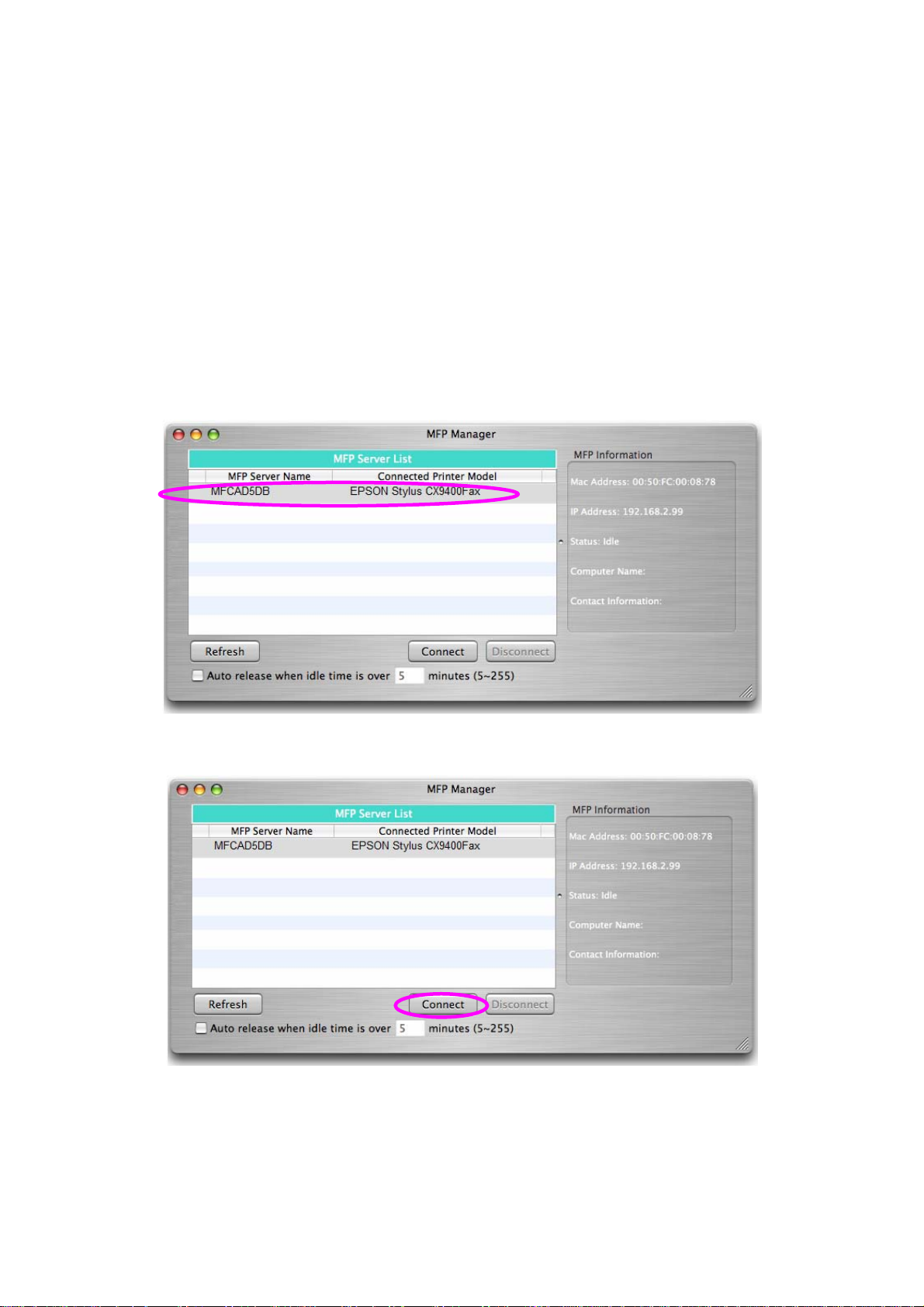
1. Go to ‘’Application/Utility” and click “MFP Manager”.
2. In the “MFP Manager”, select the all-in-one you would like to use.
3. Click the “Connect” button to connect to the all-in-one printer.
4. You are able to use the all-in-one printer for printing, scanning or reading
the memory card over the MFP Server.
4
Page 16

If you have finished using the all-in-one printer, please click “Disconnect”
Tip:
to release it. Other users can’t use the all-in-one printer until it is released.
5
Page 17
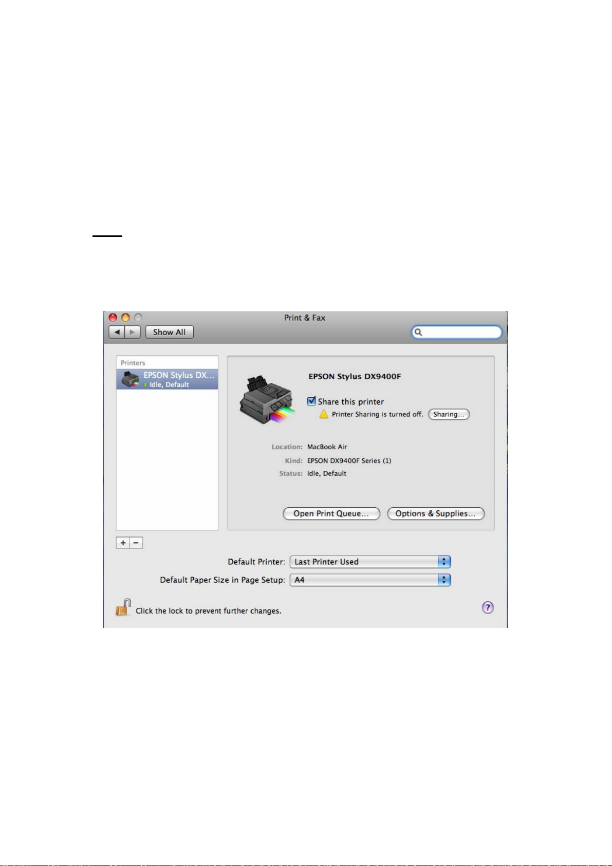
3.1 Printing
After you manually add the all-in-one printer to “Printers and Faxes” in MAC.
You can select the printer for printing a document through MFP Server by
following the steps below. Be sure to connect the all-in-one you want to use on
the list of MFP manager first.
Tip: If you have sent a print job to it while the all-in-one printer is connecting to
another user, you may be prompted that the device is not found or the
document failed to print. Please resend the print job after the all-in-one printer
is idle or not connected.
6
Page 18
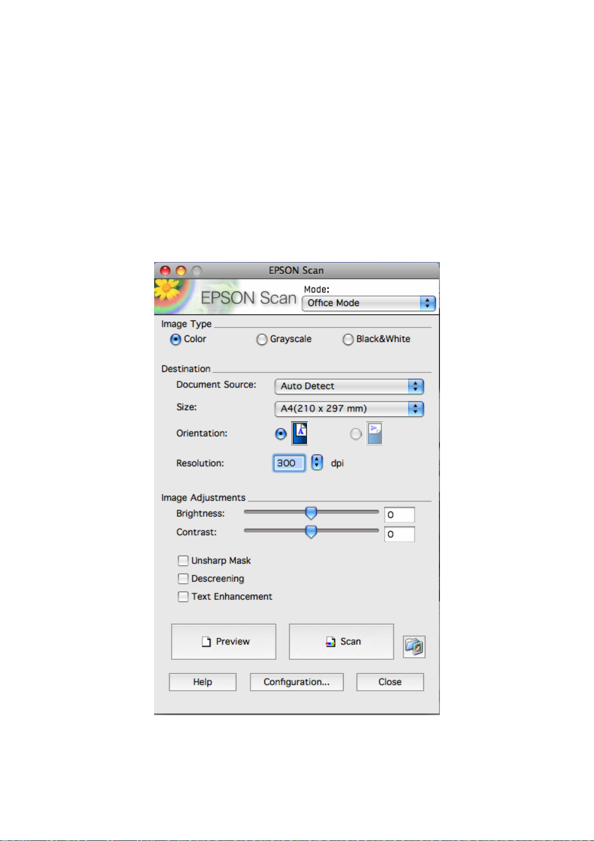
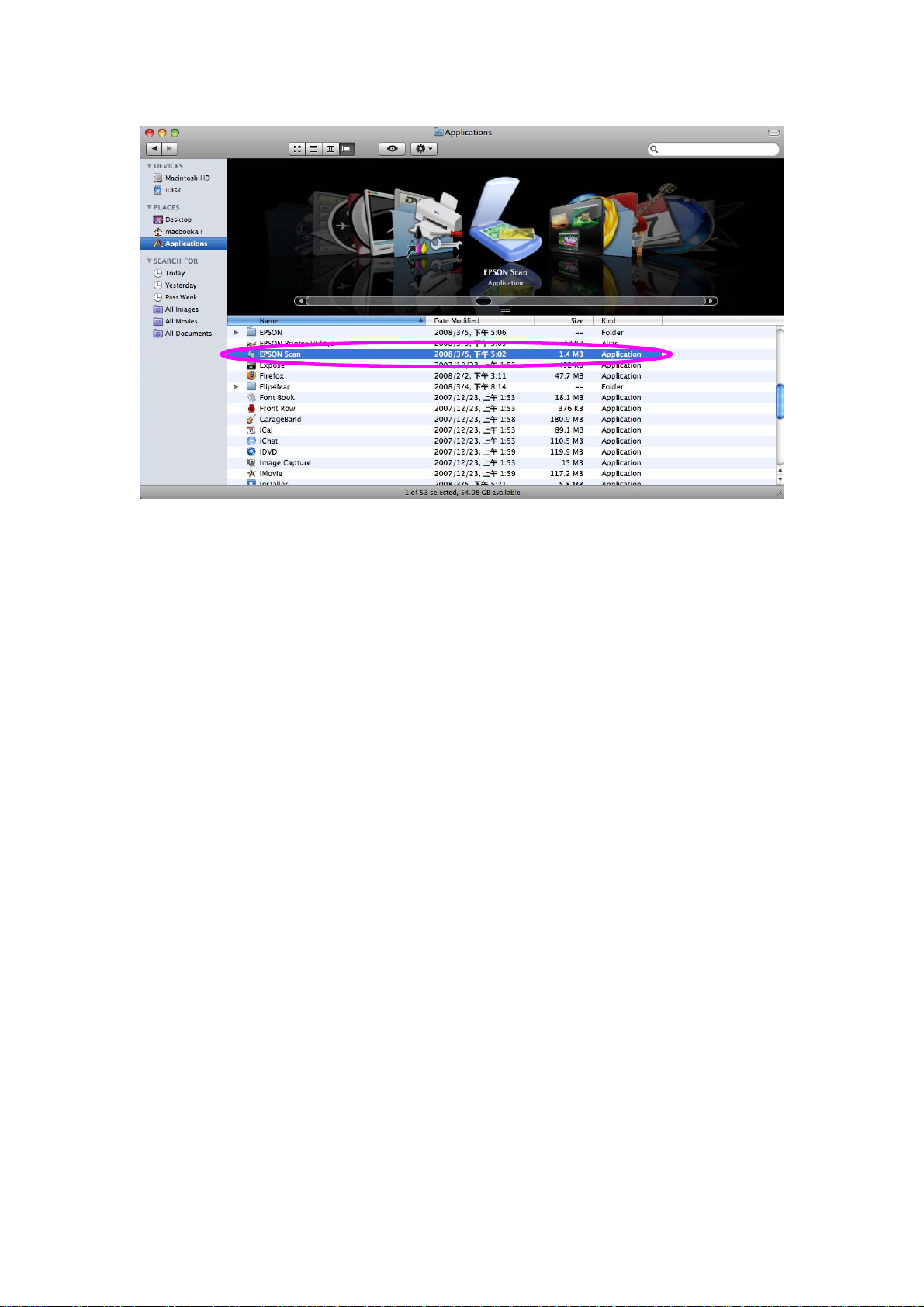
3.2 Scanning
The all-in-one printer provides a scan utility for users. You can scan pictures or
documents through the utility. In MAC, you can also scan from the MAC
scanning utility or use third party scanning utilities such as Photoshop,
Photoimpact, Paint Shop Pro, etc. Be sure to connect the all-in-one you want
to use on the list of MFP manager first.
An example: EPSON CX-8400/9400 Series Utilities
7
Page 19
MAC Scanning Utility
8
Page 20

3.3 Reading Memory Cards
You can read the files from a memory card through the MFP Server. Be sure to
connect the all-in-one you want to use on the list of MFP manager first.
9
Page 21

4. MFP Manager in MAC
4.1 MFP Server List
The “MFP Manager” can automatically find the MFP Server in the network and
show it in the MFP Server List. You can select an all-in-one printer and click
“Connect” to use the printer as if you had directly connected the printer to your
computer through a USB cable. The MFP manager also displays information
about the connection status.
When you don’t want to use the all-in-one printer, please click “Disconnect” so
that other users can use the device. If you forget to disconnect the all-in-one
printer, the MFP Server will be disconnected after five minutes automatically.
You can configure the time period; please refer to the description in the
following table.
If you unplug the USB cable or turn off the all-in-one printer, the device will not
display in the list. After you reconnect the USB cable or turn on the all-in-one
printer, you have to click the “Refresh” and “Connect” buttons in the “MFP
Manager” to recover the connection.
10
Page 22

MFP Server List
MFP Server List The “MFP Server List” will list all the MFP Servers within
the network. You can find information about the MFP
Server including “MFP Server Name”, “MAC ID”, “IP
Address” and the device that is connected to the MFP
Server.
MFP Server/MFP
Information
When you are clicking on the “MFP Server” in the “MFP
Server List”, you will see the “MFP Server Description”
and the “Idle Timeout” setting for the MFP Server.
MFP Server Description – It is a description that can
help users to identify where or what the MFP Server is.
Idle Timeout – From here, each user can know his/her
auto release setting. To avoid occupying the all-in-one
printer overtime, each user is recommended to enable
the “Auto Release” setting at the bottom of the “MFP
Manager” utility. It is used to automatically disconnect the
connection after the all-in-one printer is idle for a specified
period of time. By default, it is enabled to release the
all-in-one printer five minutes.
When you are clicking on the “all-in-one printer” in the
“MFP Server List”, you will see the information including
“Status”, “Computer Name” and “Contact Information”.
Status – It displays the status of the all-in-one printer
including Connected, Idle and Busy. When the status is
“Connected”, it indicates that you are connecting the
all-in-one printer. When the status is “Idle”, it indicates
that the all-in-one printer is not being used. When the
status is “Busy”, it indicates that another user is using the
all-in-one printer to scan, print, etc.
11
Page 23

MFP Server List
MFP Server/MFP
Information
Refresh Refresh the “MFP Server List” immediately.
Connect Let the all-in-one printer be connected to your computer.
Disconnect Disconnect the selected all-in-one printer.
Auto Release when
Computer Name – It display the computer name of the
user who is connecting to the all-in-one printer.
Contact Information – When the current user has set his
“Contact Information”, you can see it here. You can
contact the current user to disconnect the all-in-one
printer.
To avoid occupying the all-in-one printer overtime, you
idle time is over xx
minutes (5-255)
can set-up the auto release function. It is used to
automatically disconnect the current connection after the
all-in-one printer is idle for a specified period of time. By
default, it is enabled to auto release the all-in-one printer
after five minutes. You can set the time period longer; the
maximum setting is 255 minutes.
12
Page 24

4.2 Option Settings
4.2.1 General Setting
General Setting
Run MFP Manager when
MAC starts
Minimized when start
MFP Manager
Refresh status every xx
seconds. (5~300)
Your Contract
Information
Execute the “MFP Manager” when MAC starts every
time. By default, it is enabled.
Minimize the “MFP Manager” to an icon in the
system tray when you start the “MFP Manager”. By
default, it is enabled.
Set up the refresh interval for device status update.
By default, it is enabled.
Enter your contact information here. When you
connect to the all-in-one printer, your contact
information will be displayed on the right side of the
program for other users to contact you.
13
Page 25

4.2.2 Search for MFP Server
If MFP Server is not in the same network as your computer, you can enter the
IP Address of the MFP Server to do remote search. The MFP Server in the
“Remote MFP Server List” will be added to the “MFP Server List” for you to
configure.
Note:
If the remote MFP Server you have searched is behind a NAT Router, the MFP
Server may not operate normally.
14
Page 26

5. Server Configuration in MAC
5.1 Introduction
This chapter introduces the MFP Server’s system configuration utility in MAC
environment. This utility provides the most complete management and
configuration functions on the MFP Server side. This utility only provides
configuration functions for MFP Server itself; it does not include configuration
functions for client side or other file servers in the network environment.
The Configuration Utility provides the following configuration and management
functions:
Search MFP Server: Search All Available MFP Servers on the Network.
Status: Display MFP Server Network Status.
General Configuration: Configure general settings about the MFP Server
such as Server Name, Password, etc.
TCP/IP Configuration: IP Address and DHCP Server Configuration.
System Configuration: MFP Server Network Ability Setting and Firmware
Upgrade.
Wireless Configuration: Search for the available wireless networks and
configure the wireless settings of the MFP Server for the wireless
connection.
15
Page 27

5.2 Search for All Available MFP Server
To run the “Server Manager” configuration utility, click the “Search” button . Th e
configuration utility will delay for several seconds because the utility is using
the system’s available network protocols to search for all MFP Servers on the
network. All available MFP Servers will be listed under “MFP Server List” on
the left side of the window.
You must select the MFP Server you would like to configure from the list. The
system will, at the same time, display the selected MFP Server’s status on the
right side of the window.
16
Page 28

5.3 Status of MFP Server
17
Page 29

Click the “Status” button on the tool bar. The status of the currently selected
MFP Server will be shown on the right side of the window, go to ‘’System’’,
‘’Printer’’, ‘’TCP/IP’’ and ‘’Wireless’’ for detail status. The information about the
MFP Server includes Device Name, MFP Server Name, Model Type, Firmware
Version, MAC Address, status of each server port, IP address, subnet mask,
default gateway and supported printing protocols…etc.
You can refresh the MFP Server’s status by click the “Refresh” button .
18
Page 30

5.4 General Setting
Double click the “General” button on the tool bar. The setup items of the
current selected MFP Server will be shown on the right side of the window.
A screen will pop up to verify “User Name” and “Password” of the MFP Server.
The default values are: User Name: admin, Password: 1234.
19
Page 31

When you click save, a ‘’what to do’’ message will pop up, please click
Tip:
“Reboot” to restart the MFP Server to let the settings take effect, or click
‘’cancel’’ to save the setting and go to further settings.
You can configure the “Server Name”, “User Name” and “Password” here.
Server Name, the name of the MFP Server. You can use this name to identify
the MFP Server when you are searching for the MFP Server by the “Server
Manger” utility.
MFP Server Description, to enter a description of the MFP Server such as
location or other information, to help users find the MFP Server easily.
User Name / Password is used to authenticate the administrator to login the
MFP Server for configuring it from the “Server Manger” utility or the Web
Management tool.
20
Page 32

5.5 TCP/IP Configuration
Double click the “TCP/IP” button. The TCP/IP configuration window will pop up.
You can configure the MFP Server to automatically get an IP address from a
DHCP server or manually specify a static IP.
IP Address Assignment:
If you need the MFP Server to automatically get an IP from a DHCP server,
select “Auto IP”. You also can select “S tatic IP” to manually assign “IP Address”,
“Subnet Mask” and “Gateway” for the MFP Server. The default IP Address
settings of the MFP Server are as follows.
IP Address: 192.168.2.2
Subnet Mask: 255.255.255.0
Auto IP – The IP Address information of the MFP Server obtained from a
DHCP Server will be displayed in the address field. If no DHCP Server is
present, you have to assign the information manually.
Static IP – Manually assign the IP address information in the same network
with your computer to the MFP Server.
21
Page 33

5.6 System Configuration
Double click the “System” button. The System configuration window will pop up.
In the System configuration page, you can upgrade the firmware, reset to
factory default, reboot the system or set the force release port for this MFP
Server.
Firmware Upgrade: You can use this “Firmware Upgrade” tool to update to
the newest firmware of the MFP Server. Click “ ” button and select
the correct firmware in your PC. After selecting the firmware file click
“ ” button to activate the firmware update process.
Tip: Before you upgrade the firmware, please make sure that the IP Address
settings of the MFP Server are in the same network as your computer.
Reset to Default: If you want to reset the MFP Server to default factory
settings, please click “OK”.
System Reboot: If you want to reboot the MFP Server, please click ‘’System
Reboot’’.
Force Release: Click “Force Release” to help you disconnect the current
connection between the user and the connected device. This is very useful
when a user forgets to disconnect the all-in-one printer. The administrator can
release the connection and let the all-in-one printer be free to use.
22
Page 34

5.7 Wireless Configuration
Wireless Configuration Double-click the “Wireless” button. Enter user name
and password then the wireless configuration window will popup. The default
username and password are ‘’admin’’ and ‘’1234’ ’, and you are into the steps of
‘’Infrastructure Mode”.
Function: You can select “Auto”, Enable” or “Disable” to manually configure
the wireless function.
Auto – “Auto” is the default setting of the MFP Server. At this mode, the MFP
Server will automatically decide to enable or disable the wireless function.
When the MFP Server starts up, it will auto-detect if the LAN port is connected
to an active network by an Ethernet cable. If this is the case, the MFP Server
will run in Ethernet mode. If the MFP Server is not connected to an active
network by Ethernet cable, the MFP Server will run in wireless LAN mode.
Users can plug the Ethernet cable into the MFP Server, after configuring the
MFP Server features and wireless settings; they can unplug the Ethernet cable
to enable the wireless connection. This makes the configuration much easier
without creating the wireless connection in advance.
Note: After you have set the wireless function, please remove the Ethernet
cable and then re-plug the power jack of the MFP Server to activate the
23
Page 35

wireless connection.
Enable – Enable wireless function only; the MFP Server’s wireless LAN will be
enabled and Ethernet will be disabled.
Disable – Disable the wireless function, the MFP Server’s wireless LAN will be
disabled and Ethernet will be enabled.
Infrastructure: You have to let the MFP server associate with an access point.
You can let the MFP server scan for an available access point automatically or
manually assign the SSID of the access point you want to use.
If you select to let the MFP server scan for an available access point, click
‘’Site Survey’’ the following window will pop up.
The table will list the available access points near the MFP server. Select an
access point in the list and click “OK”. If you cannot find the access point that
you want to use, click “Scan” to let the MFP server scan again.
You have to go through the following security setting procedure:
24
Page 36

This MFP server supports WEP, WPA-PSK and WPA2-PSK security mode. If
you want to use WEP encryption to protect your wireless network, you have to
select “WEP’’. The wireless security setting should match other wireless
devices in the same network.
WEP Security Mode:
When you choose the encryption to ‘’WEP’’ a key format message will pop out.
25
Page 37

(p.s. this picture is temporary we will post the formal one later)
You can select to enter “10 or 26 characters” for “Hexadecimal” or “5 or 13
characters’’ for ‘’ASCII” format encryption key. Longer key length can provide
stronger security but worse communication performance.
Network Key –Simplifies the WEP encryption process by automatically
generating the WEP encryption keys for the MFP server. All you have to do is
to enter 5, 10, 13 or 26 characters key then the system will automatically
transfer to 64-bit HEX, ASCII or 128-bit HEX, ASCII keys, the rules are as
below.
If the key length is 64-bit, enter 10-digit Hex values or 5-digit ASCII values as
the encryption keys. For example: “0123456aef“ or “Guest“.
If the key length is 128-bit, enter 26-digit Hex values or 13-digit ASCII values
as the encryption keys. For example: “01234567890123456789abcdef“ or
“administrator“.
26
Page 38

WPA-PSK/WPA2-PSK Security Mode:
“WPA-PSK’’ and ‘’WPA2-PSK” can automatically transfer keys to TKIP or AES
by random.
Network Key – Enter 8 to 63 digits to be the key for authentication within the
network.
TKIP(WPA-PSK & WPA2-PSK) – TKIP (Temporal Key Integrity Protocol)
changes the temporal key every 10,000 packets. This insures much greater
security than the standard WEP security.
27
Page 39

AES(WPA2-PSK) – AES has been developed to ensure the highest degree of
security and authenticity for digital information and it is the most advanced
solution defined by IEEE 802.11i for security in a wireless network.
When you finish configuring wireless security, click “Save” and a ‘’What to do’’
message pop out. Please click ‘’Reboot’’ to let the Wireless setting take effect.
28
Page 40

6. Web Management
6.1 Introduction
The MFP Server can be configured and managed on the Web. Through the
Local Area Network, or even the Internet, the administrator can easily
configure and manage MFP Server’s various main functions in a browser.
Simply enter the MFP Server’s IP address into your browser’s address field to
manage a MFP Server by through its built-in Web Server.
The default IP Address, User Name and Password settings of the MFP Server
are as follows.
IP Address: 192.168.2.2
User Name: Admin
Password: 1234
29
Page 41

6.2 Login
You may use any Web Browser to review the status or configure the settings of
the MFP Server. After entering the IP address of the MFP Server, a login page
displays. You have to enter the correct “User Name” and “Password” before
going to the Web Management pages.
Note: Default User Name is “admin”, default password is “1234”.
30
Page 42

6.3 Device Status
6.3.1 System Status
System Information includes “Device Name”, “MFP Server Name”, “Model
Type”, “Firmware Version”, “MAC Address”, “Wireless Configuration”, and the
protocols enabled status, etc.
31
Page 43

6.3.2 Printer Status
This page lists information and status of the all-in-one printer or printer
connected to the MFP Server port. The status of the all-in-one printer or printer
includes “Connected”, ”Ready”, “Off Line” or “Paper Out”.
Connected: a user has clicked the “Connect” button in the “MFP Manager”
utility. The user’s computer and the all-in-one printer are connected.
Ready: the all-in-one printer or printer is not connected by a user and is ready
to use.
Off Line: the all-in-one printer or printer is not connected to MFP Server
through a USB cable, or it is turned off.
Paper Out: the all-in-one printer or printer is not connected by a user and is
out of paper.
32
Page 44

6.3.3 TCP/IP Status
This page lists all TCP/IP settings of the MFP Server including “IP Address”,
“Subnet Mask” and “Gateway”. It also can tell whether the DHCP server is “On”
or “Off”.
33
Page 45

6.4 Setup Wizard
Note: You can configure the MFP Server from the Setup Wizard. To let the
changes take effect, you have to click “Save Settings” in the menu on the left
side to reboot the MFP Server.
6.4.1 System
6.4.1.1 Admin Password
You can change the MFP Server name and port name from here.
MFP Server Name: the name of the MFP Server. You can use this name to
identify the MFP server when you are searching for if using by the “Server
Manager” utilities.
PORT Name: The name of the port which MFP server plugs on. The default
port name is ‘’p1’’.
34
Page 46

You can change the MFP Server name and password from here.
MFP Server Name: the name of the MFP Server. You can use this name to
identify the MFP Server when you are searching for if using by the “Server
Manager” utilities.
Password: enter the password you want to change for the MFP Server. The
password can be up to 7-6 digits in alphanumeric format. The default password
is “1234”.
Re-type Password: enter the same password for the MFP Server again.
35
Page 47

6.4.1.2 Advanced Settings
Some advanced feature of the MFP Server can be set here.
TCP/IP Printing (LPR/IPP/RAW): The MFP Server supports TCP/IP network
protocol and LPR/IPP/RAW printing protocols. By default these protocols are
enabled.
36
Page 48

6.4.2 Wireless
If you want to use the MFP Server through a wireless LAN, please set up the
MFP Server through Ethernet first and make sure your wireless LAN setting is
correct. After setting the wireless LAN, unplug the Ethernet cable and restart
the MFP Server. Then you can start to use the MFP Server through the
wireless LAN. If the wireless configuration does not work, please plug in the
Ethernet cable again, restart the MFP Server and configure the MFP Server
through Ethernet until the wireless LAN settings are correct.
You can enable/disable the wireless function and set up the wireless
parameters for the MFP Server from here. The parameters include “Function”
and “ESSID”. You can manually set the wir eless network that you want to
connect in this page or use the “Site Survey” function to automatically search
for an available wireless network and associate with it.
Function allows you to disable, enable or let the MFP Server auto select to
connect to a wired or wireless network. If “Disable” is selected, the MFP Server
can only connect to the network through wired Ethernet. If “Enable” is selected,
the MFP Server can only connect to the network through a Wireless LAN. If
“Auto” is selected, the MFP Server can automatically decide to enable or
disable the wireless function. The MFP Server only can work in either Ethernet
or wireless LAN mode. It cannot work in both Ethernet and wireless LAN mode
at the same time. When the MFP Server starts up, it will auto-detect if the LAN
port is connected to an active network by an Ethernet cable. If the MFP Server
is connected to an active network by Ethernet cable when starting up, the MFP
Server will run in Ethernet mode. If the MFP Server is not connected to an
active network by Ethernet cable when starting up, the MFP Server will run in
37
Page 49

wireless LAN mode. The MFP Server default is in “Auto” mode.
ESSID is the unique name identified by in a wireless LAN. The ID prevents the
unintentional merging of two co-located WLANs. Please make sure that the
ESSID of all stations and access points in the same WLAN network are the
same.
Channel Number is the channel number of your wireless LAN. It is fixed on
channel 11th.
38
Page 50

6.4.2.1 Site Survey
You can use this “Site Survey” function to search for available access points in
your location. In the list is the information for all available access points or
wireless stations, including SSID, BSSID, Channel, Type, Encryption and
Signal Strength. You can select one wireless device in the list for this MFP
Server to associate with or go back to Wireless page to manually set up the
wireless parameters.
There is “WLAN Function” setting lets you to set up Auto/Disable/Enable
wireless function of the MFP Server . Please refer to section 6.4.2 to know more
about the setting.
39
Page 51

6.4.2.2 Encryption
This MFP Server supports WEP and WPA-PSK security mode. If you want to
use WEP encryption to protect your wireless network, you have to select
“WEP”. If you want to use WPA-PSK, you have to select “WPA-PSK” (for an
infrastructure network or “WPA-None” (enables WPA security for an ad hoc
network). The wireless security setting should match other wireless devices in
the same network.
WEP Security Mode:
Key Length – You can choose “64-bit” to use WEP with 64-bit key length
encryption or choose “128-bit” to use WEP with 128-bit key length encryption.
The longer key length can provide better security but worse transmission
throughput.
Key Format – You may select to use ASCII Characters (alphanumeric format)
or Hexadecimal digits (in the "A-F", "a-f" and "0-9" range) to be the WEP Key.
PassPhrase – A “PassPhrase” simplifies the WEP encryption process by
automatically generating the WEP encryption keys for the MFP Server.
40
Page 52

Default Key – Select one of the four keys to encrypt your data. Only the key
you select in the “Default key” will take effect.
Key 1 – Key 4 – The WEP keys are used to encrypt data transmitted within the
wireless network. Fill the text box by following the rules below.
64-bit WEP: input 10-digit Hex values (in the "A-F", "a-f" and "0-9" range) or
5-digit ASCII characters as the encryption keys. For example: “0123456aef“ or
“Guest“.
128-bit WEP: input 26-digit Hex values (in the "A-F", "a-f" and "0-9" range) or
10-digit ASCII characters as the encryption keys. For example:
“01234567890123456789abcdef“ or “administrator“.
41
Page 53

WPA-PSK Mode:
“WPA-PSK” requires users to select the advanced encryption methods, (i.e.
TKIP or AES) and enter a set of keys.
TKIP – TKIP (Temporal Key Integrity Protocol) changes the temporal key every
10,000 packets. This insures much greater security than the standard WEP
security.
AES – AES has been developed to ensure the highest degree of security and
authenticity for digital information and it is the most advanced solution defined
by IEEE 802.11i for security in the wireless network.
WPA Pre-Shared key – Enter 8 to 63 digits of ASCII format to be the key for
authentication within the network.
When you finish configuring the wireless security, click “Save & Next” to
confirm the configuration.
42
Page 54

WPA2-PSK Mode Security Mode:
TKIP – TKIP (Temporal Key Integrity Protocol) changes the temporal key every
10,000 packets. This insures much greater security than the standard WEP
security.
Pre-shared Key Format – Select the type of pre-shared key, you can select
Passphrase (8 or more alphanumerical characters, up to 63), or Hex (64
characters of 0-9, and a-f).
WPA Pre-Shared Key –Enter 8 to 63 digits of ASCII format to be the key for
authentication within the network.
When you finish configuring the wireless security, click “Save & Next” to
confirm the configuration.
43
Page 55

6.4.3 TCP/IP
You can configure the MFP Server to automatically get an IP address from
DHCP server or manually specify a static IP.
If you need the MFP Server to automatically get an IP address from a DHCP
server, select “Enable Obtain TCP/IP Settings Automatically (Use DHCP/
BOOTP)”. You also can select “Disable Use the following TCP/IP Settings” to
manually assign an “IP Address”, “Subnet Mask” and “Gateway” for the MFP
Server.
44
Page 56

6.4.4 Save Settings
After configuring the MFP Server, you have to click “Save Settings” to save the
settings and restart the system.
45
Page 57

6.5 System Tools
6.5.1 Load Default
You can use this page to restore the factory default settings. All of your
previous setting will be cleared.
46
Page 58

6.5.2 Upgrade Firmware
You can upgrade new firmware for this MFP Server in this page. Click
“Browse” to select the new firmware, and then click “OK”. The firmware will be
updated in several minutes.
Be aware that if you have started upgrading firmware, you have to follow all the
upgrading steps or the MFP Server can’t return to normal configuration.
47
Page 59

7. Troubleshooting
1. The MFP Server is not found even after searching with the “MFP Manager”.
Check if the power adapter and the network cable are connected to the
MFP Server properly.
Check if the LAN and Ready LEDs are turned on.
Check if the IP Address of the MFP Server is in the some network
segment as your computer.
- If you are not sure of the IP Address setting of the MFP Server, please
check the TCP/IP setting of the MFP Server from the “Server
Manager”.
2. How do to change the IP Address of the MFP Server?
A DHCP Server is installed in the network
If a DHCP Server is installed, you can let the MFP Server get an IP
Address from the DHCP Server automatically.
1. Open “Server Manager” and then select “TCP/IP” setting.
2. Select “Auto IP” and click “Save”.
3. Reboot the MFP Server.
Set up the IP Address Manually
1. Open “Server Manager” and then select “TCP/IP” setting.
2. Select “Static IP” and enter the IP Address and Subnet Mask that
match your computer. Click “Save”.
3. Reboot the MFP Server.
Note: Setting a static IP Address for MFP Server is recommended since
DHCP assignment may dramatically change the IP Address of the MFP
Server.
3. A user stays connected to the MFP Server.
Contact the current user and ask to disconnect the device.
If the user forgets to disconnect the device, you can ask the
administrator to release the device.
48
Page 60

4. I can’t use the all-in-one printer to scan, print, use the card reader, or fax a
file even I have followed the instructions in the manual.
Attach the all-in-one printer to a PC directly and make sure it is
operating correctly.
5. My computer has installed a firewall, and the MFP Server can’t work
normally.
Some firewalls, for example, the “Network Access Manager” firewall
program installed with the nVidia network card may block the
communication between the MFP Server and your computer; you have
to add the MFP Server programs to the exception list of your firewall.
The programs are as follows.
1. Add the “servoap.exe” program to the exception list.
2. Add “mfpagent.exe” program to the exception list.
49
Page 61

50
 Loading...