

Page 1
Wireless LAN Access Point
with 5-Port Switch
EW-7205APS
User’s Manual
Page 2

Table of Contents
Chapter 1 Introduction............................................................................. 1
1.1 Package Contents .......................................................................................... 1
1.2 Features ......................................................................................................... 2
1.3 Specifications................................................................................................ 2
1.4 Physical Description ..................................................................................... 3
Chapter 2 Wireless LAN Access Point Connection................................ 5
Chapter 3 Wireless LAN Access Point Configuration ........................... 6
3.1 Getting Started .............................................................................................. 6
3.2 Configuring the Access Point ....................................................................... 9
3.2.1 System Information.............................................................................................. 9
3.2.2 Channel and ESSID ...........................................................................................10
3.2.3 Encryption..........................................................................................................11
3.2.4 MAC Address Filtering......................................................................................14
3.2.5 IEEE 802.1X ...................................................................................................... 15
3.2.6 System Utility .................................................................................................... 20
3.2.7 DHCP Client Log...............................................................................................23
3.2.8 Configuration Tools ........................................................................................... 24
3.2.9 Firmware Upgrade ............................................................................................. 25
3.2.10 Reset................................................................................................................... 26
Chapter 4 Troubleshooting .................................................................... 28
Page 3

Introduction
Chapter 1 Introduction
This product is a Wireless LAN Access Point with 5-port 10/100Mbps Fast Ethernet
Switch, which allows you to build your wireless network without buying an
additional hub or switch. It is the ideal product that provides you the best solution for
building both wireless network and 10/100Mbps Fast Ethernet backbone.
The product supports advanced user authentication including 64/128-bit WEP
Encryption and IEEE 802.1X ensures a high level of security for wireless networking.
In additional to corporate use, this Access Point can also be implemented in the
public arena such as airports, hotels based on the advanced 802.1X authentication
mechanism.
The product’s dipole antenna is detachable by connecting to a RP-SMA connector.
Users can install a high gain antenna to the connector for better network link quality
so that you can build wireless network with more flexibility.
This product provides easy to use user interface and allows users to configuring from
web browser. Also it integrates DHCP server to provide multiple wireless and wired
users to get their IP address automatically. With the versatile of features, this product
is the best choice for you to integrate your wireless and wired network seamlessly.
1.1 Package Contents
The Access Point includes the following items:
One Access Point
One Power Adapter
One User’s Manual
1
Page 4

1.2 Features
Complies with the IEEE 802.11b (DSSS) 2.4GHz specification.
High data rate 11, 5.5, 2 and 1Mbps network speed.
Seamlessly integrate wireless and wired Ethernet LAN networks.
Provides an internal 5-port switch for wired Ethernet connection.
Detachable external antenna provides users flexibility to install the wireless
network with high gain antenna.
Auto rate fallback in case of obstacles or interferences.
Provides 64/128-bit WEP Data Encryption function to protect the wireless
data transmissions.
Supports IEEE 802.1X, enabling enhanced WLAN security.
Introduction
Built-in proprietary authentication server based on the IEEE 802.1X standard.
Built-in DHCP Server supports auto IP address assignment.
Supports Web-based configuration.
1.3 Specifications
Standards: IEEE 802.11b (Wireless), IEEE 802.3 and IEEE 802.3u (Wired),
IEEE 802.11X
Data Rate: 11/5.5/2/1Mbps auto fallback
Security: 64/128-bit WEP Data Encryption, IEEE 802.1X
Frequency Band: 2.400~2.4835GHz (Industrial Scientific Medical Band)
Modulation: CCK@11/5.5Mbps, DQPSK@2Mbps and DBPSK@1Mbps
Radio Technology: Direct Sequence Spread Spectrum (DSSS)
Antenna: External detachable dipole antenna (with RP-SMA connector)
Connectors: 10/100Mbps RJ-45 x 5 (Normal x 4, Uplink x 1)
Power: 12VDC, 1A
Transmit Power: 15dBm (Typical)
LEDs: Power, LAN Link/Activity and 10/100M Speed, Wireless
Link/Activity
Dimension: 33(H) x 188(W) x 135(D) mm
2
Page 5
Introduction
Temperature:
Operating: 32~131°F (0~55°C)
Storage: -4~158°F(-20~70°C)
Humidity: 0-90% (Noncondensing)
Certification: FCC, CE
1.4 Physical Description
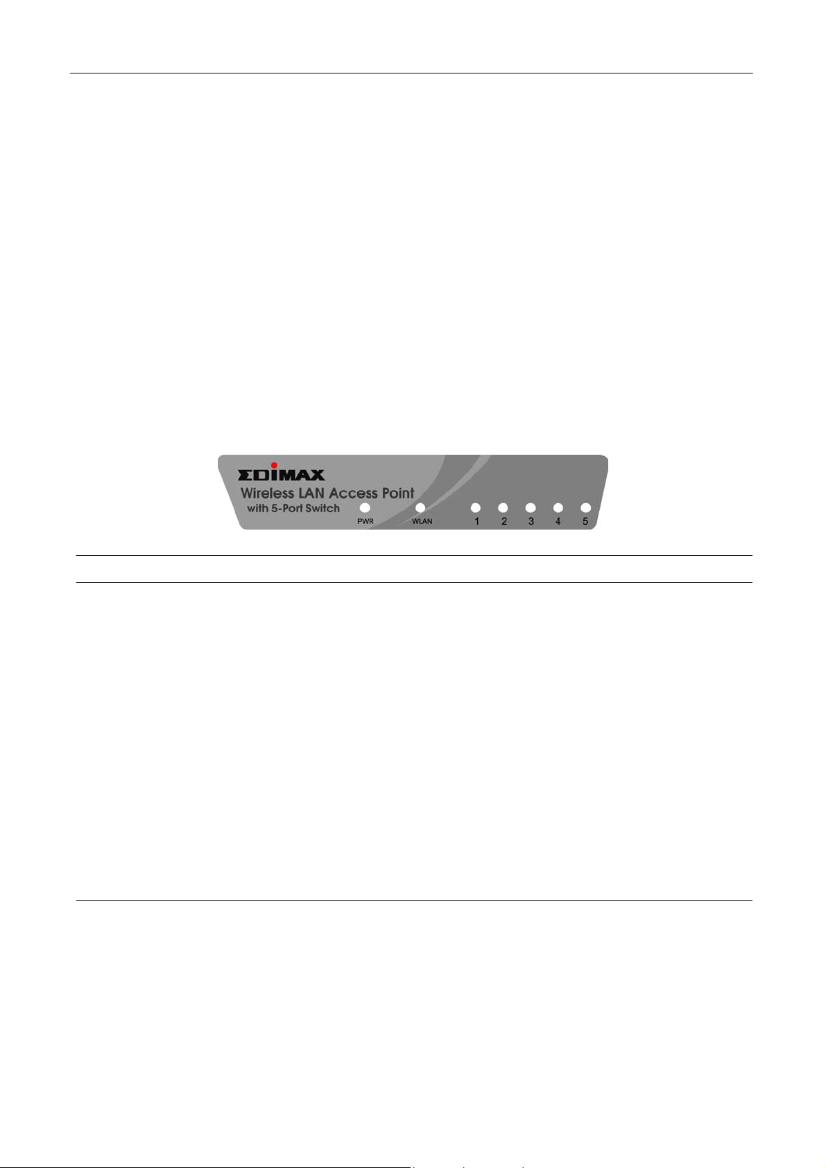
Front Panel
On the Access Point’s front panel there are LED lights that inform you of the Access
Point’s current status. Below is an explanation of each LED.
LED Color Status Description
Lit Power is supplied.
Power Green
Off No Power.
Flash Antenna is transmitting or receiving data. Wireless
Green
TX/RX
Off Antenna is not transmitting or receiving data.
Lit A valid link is established.
Amber
Flash Data packets are received.
(100Mbps)
LAN
Link/Activity
Off No link is established.
Lit A valid link is established.
Green
Flash Data packets are received.
(10Mbps)
Off No link is established.
Back Panel
Access Point’s connection ports are located on the back panel. Below is the
description of each connection port.
3
Page 6

Antenna Connector
This round connection is standard Reverse SMA connector where any antennas
with Reverse SMA connector can connect to the Access Point.
DC Adapter Port
Insert the power jack of the power adapter into this port.
10/100Mbps
Introduction
The Access Point’s LAN ports are where you connect your LAN’s PCs.
Uplink Port
Using this port connects to Ethernet network devices, such as a hub, switch, or
router directly.
Reset
The Reset button allows you to do one of two things.
1) If problems occur with your Access Point, press the reset button with a
pencil tip (for less than 4 seconds) and the Access Point will re-boot itself,
keeping your original configurations.
2) If problems persist or you experience extreme problems or you forgot your
password, press the reset button for longer than 4 seconds and the Access
Point will reset itself to the factory default settings (warning: your original
configurations will be replaced with the factory default settings).
4
Page 7

Wireless LAN Access Point Connection
Chapter 2 Wireless LAN Access Point
Connection
1. Locate an optimum location for the Wireless LAN Access Point.
The best location for your Access Point is usually at the center of your wireless
network, with line of sight to all of your mobile stations.
2. Connect the Wireless LAN Access Point to your 10/100Mbps network.
Connect one end of standard UTP cable to the Access Point’s Uplink Port and
connect the other end of the cable to a switch or a hub’s regular port. The Access
Point will then be connected to your existed 10/100Mbps Network.
3. Connect your PCs to the Wireless LAN Access Point directly.
This Access Point has a built-in 5-Port Fast Ethernet Switch, allowing you to
build a wired LAN network directly by connecting your PCs to the Access Point.
Connect one end of standard UTP cable to the Access Point and connect the other
end of the cable to your PCs. A small LAN network will be built.
4. Connect the AC Power Adapter to the Wireless LAN Access Point’s Power
Socket.
Only use the power adapter supplied with the Access Point. Using a different
adapter may damage the product.
The Hardware Installation is complete.
5
Page 8

Wireless LAN Access Point Configuration
Chapter 3 Wireless LAN Access Point
Configuration
3.1 Getting Started
This Access Point provides web-based configuration tool allowing you to configure
from wired or wireless stations. Follow the instructions below to get started
configuration.
From Wired Station
1. Make sure your wired station is in the same subnet with the Access Point.
The default IP Address and Sub Mask of the Access Point is:
Default IP Address: 192.168.2.1
Default Subnet: 255.255.255.0
Configure your PC to be in the same subnet with the Access Point.
1a) Windows 95/98/Me
1. Click the Start button and select Settings, then click Control Panel. The Control Panel
window will appear.
2. Double-click Network icon. The Network window will appear.
3. Check your list of Network Components. If TCP/IP is not installed, click the Add button to
install it now. If TCP/IP is installed, go to step 6.
4. In the Network Component Type dialog box, select Protocol and click Add button.
5. In the Select Network Protocol dialog box, select Microsoft and TCP/IP and then click the
OK button to start installing the TCP/IP protocol. You may need your Windows CD to
complete the installation.
6. After installing TCP/IP, go back to the Network dialog box. Select TCP/IP from the list of
Network Components and then click the Properties button.
7. Check each of the tabs and verify the following settings:
• Bindings: Check Client for Microsoft Networks and File and printer sharing for
Microsoft Networks.
• Gateway: All fields are blank.
• DNS Configuration: Select Disable DNS.
• WINS Configuration: Select Disable WINS Resolution.
6
Page 9

Wireless LAN Access Point Configuration
• IP Address: Select Specify an IP Address. Specify the IP Address and Subnet Mask
as following example.
IP Address: 192.168.2.3 (any IP address within 192.168.2.2~192.168.2.254 is
available, do not setup 192.168.2.1)
Subnet Mask: 255.255.255.0
8. Reboot the PC. Your PC will now have the IP Address you specified.
1b) Windows 2000
1. Click the Start button and select Settings, then click Control Panel. The Control Panel
window will appear.
2. Double-click Network and Dial-up Connections icon. In the Network and Dial-up
Connection window, double-click Local Area Connection icon. The Local Area Connection
window will appear.
3. In the Local Area Connection window, click the Properties button.
4. Check your list of Network Components. You should see Internet Protocol [TCP/IP] on
your list. Select it and click the Properties button.
5. In the Internet Protocol (TCP/IP) Properties window, select Use the following IP address
and specify the IP Address and Subnet mask as following.
IP Address: 192.168.2.3 (any IP address within 192.168.2.2~192.168.2.254 is
available, do not setup 192.168.2.1)
Subnet Mask: 255.255.255.0
6. Click OK to confirm the setting. Your PC will now have the IP Address you specified.
1c) Windows NT
1. Click the Start button and select Settings, then click Control Panel. The Control Panel
window will appear.
2. Double-click Network icon. The Network window will appear. Select the Protocol tab from
the Network window.
3. Check if the TCP/IP Protocol is on your list of Network Protocols. If TCP/IP is not installed,
click the Add button to install it now. If TCP/IP is installed, go to step 5.
4. In the Select Network Protocol window, select the TCP/IP Protocol and click the Ok
button to start installing the TCP/IP protocol. You may need your Windows CD to
complete the installation.
5. After you install TCP/IP, go back to the Network window. Select TCP/IP from the list of
Network Protocols and then click the Properties button.
6. Check each of the tabs and verify the following settings:
7
Page 10
Wireless LAN Access Point Configuration
• IP Address: Select Specify an IP address. Specify the IP Address and Subnet Mask
as following example.
IP Address: 192.168.2.3 (any IP address within 192.168.2.2~192.168.2.254 is
available, do not setup 192.168.2.1)
Subnet Mask: 255.255.255.0
• DNS: Let all fields are blank.
• WINS: Let all fields are blank.
• Routing: Let all fields are blank.
7. Click OK to confirm the setting. Your PC will now have the IP Address you specified.
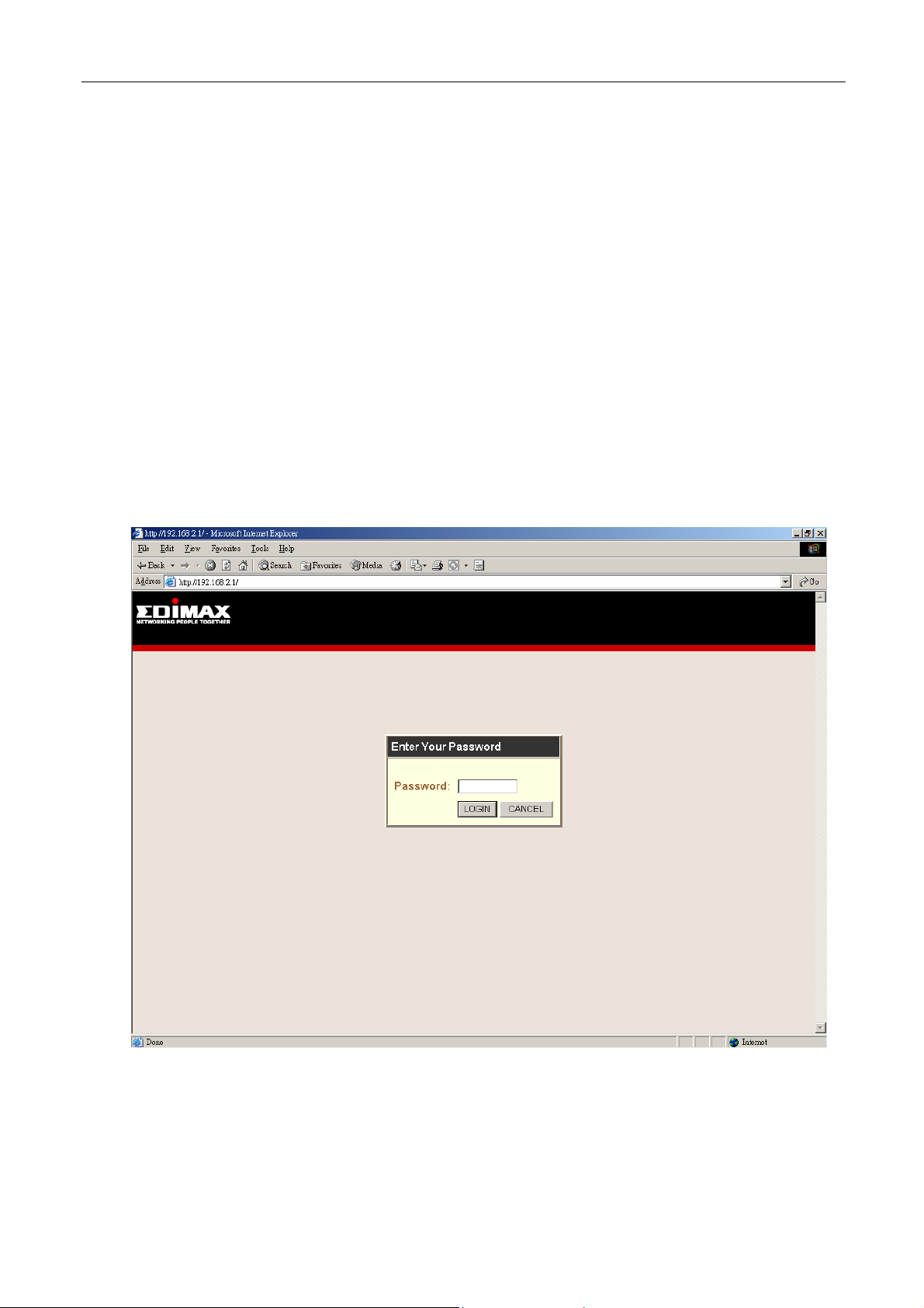
2. Enter 192.168.2.1 from Web Browser to get into the Access Point’s
configuration tool.
3. The default Password for the Access Point is blank. Press Login button directly.
4. You can start configuring the Access Point.
8
Page 11

Wireless LAN Access Point Configuration
From Wireless Station
1. Make sure your wireless station is in the same subnet with the Access Point.
Please refer to the step 1 above for configuring the IP Address and Sub Mask of
the wireless station.
2. Connect to the Access Point.
The Access Point’s ESSID is “default” and the WEP Encryption function is
disabled. Make sure your wireless station is using the same ESSID as the
Access Point and associate your wireless station to the Access Point.
3. Enter 192.168.2.1 from Web Browser to get into the Access Point’s
configuration tool.
4. Press Login button and you are available to configure the Access Point now.
3.2 Configuring the Access Point
3.2.1 System Information
On this screen, you can see the general information of the Access Point including
MAC Address, WLAN MAC Address and Hardware Version, etc.
9
Page 12

Wireless LAN Access Point Configuration
3.2.2 Channel and ESSID
You can set parameters that are used for the wireless stations to connect to this
Access Point. The parameters include ESSID, Transmission Rate, Basic Rate and
Channel.
Parameter Description
ESSID
Transmission Rate
The ESSID (up to 32 printable ASCII characters) is the unique name
identified in a WLAN. The ID prevents the unintentional merging of two
co-located WLANs. Please make sure that the ESSID of all stations in
the network are the same. The default ESSID is “default”.
The highest data transmission speed supports by the Access Point. If
Fully Automatic is selected, the Access Point will automatically select
the optimum rate allowed in the environment.
10
Page 13

Parameter Description
Basic Rate
The lowest data transmission speed supports by the Access Point. If All
is selected, the Access Point will automatically select the optimum rate
allowed in the environment. The default value is “1~2Mbps”.
Wireless LAN Access Point Configuration
Channel
Hidden
Click Apply button at the bottom of the screen to save the above configurations. You can now configure
Select the appropriate channel from the list provided to correspond with
your network settings. Channels differ from country to country.
Channel 1-11 (North America)
Channel 1-14 (Japan)
Channel 1-13 (Europe)
Channel 10-11 (Spain)
Channel 10-13 (France)
There are 14 channels available.
If Auto is selected, the Access Point will automatically select a channel
which is unused by another Access Points within the wireless network.
If you concern the security issue, you can check Hidden. Then only
devices with the same ESSID as this Access Point can access the
wireless LAN.
other advance sections or start using the Access Point.
3.2.3 Encryption
WEP is an authentication algorithm, which protects authorized Wireless LAN users
against eavesdropping. The Authentication type and WEP key must be the same on
the wireless station and on the Access Point. This Access Point supports 64/128-bit
WEP Encryption function. With this function, your data will be transmitted over the
Wireless network securely.
11
Page 14

Wireless LAN Access Point Configuration
Parameter Description
WEP Mode
You can select the 64-bit or 128-bit to encrypt transmitted data. Larger
WEP key length will provide higher level of security, but the throughput
will be lower. You also can select Disable to transmit data without
encryption.
12
Page 15

Wireless LAN Access Point Configuration
13
Page 16

Parameter Description
Wireless LAN Access Point Configuration
Passphrase
Key 1 - Key 4
Default Key
Enter a maximum of 32 alphanumeric characters in the text box and
press Generate button, the Access Point will generate a WEP key
automatically (refer to the 128-bit screen, the key is displayed after the
Access Point generate the key for the wording “test”). It is easy for user
to setup the WEP key. Note that this passphrase may not work with some
wireless products due to possible incompatibility with other vendor’s
passphrase generators.
The WEP keys are used to encrypt data transmitted in the wireless
network. Fill the text box by following the rules below.
64(40)-bit WEP: input 10 digit Hex values (in the “A-F”, “a-f” and “0-9”
range) as the encryption keys.
128-bit WEP: input 26 digit Hex values (in the “A-F”, “a-f” and “0-9”
range) as the encryption keys.
Select one of the four keys to encrypt your data (only in 64-bit mode).
Only the key you select it in the “Default key” will take effect.
Clear All Keys
Click Apply button at the bottom of the screen to save the above configurations. You can now configure
other advance sections or start using the Access Point.
Press Clear All Keys button to clear all the WEP keys.
3.2.4 MAC Address Filtering
This Access Point provides MAC Address Filtering, which prevents the unauthorized
MAC Addresses from accessing your Wireless LAN.
14
Page 17

Wireless LAN Access Point Configuration
Parameter Description
Filtering
Setting
MAC Address Filtering Table
Click Apply button at the bottom of the screen to save the above configurations. You can now configure
other advance sections or start using the Access Point.
Enable or disable the MAC Address Filtering function.
You can select to permit or prohibit the MAC addressed listed in the MAC
Address Filtering Table to access your wireless LAN.
There are 32 sets MAC Address you can set here. Fill the MAC
Addresses of wireless stations you want to permit or prohibit to access
your network in this table.
3.2.5 IEEE 802.1X
802.1X, an IEEE standard that provides an authentication framework for 802-based
LANs. 802.1X will let wireless LANs scale by allowing centralized authentication of
wireless users or stations. Based on the 802.1X framework, any wireless stations try
15
Page 18

Wireless LAN Access Point Configuration
to connect to the Access Point should be authenticated by an Authentication Server.
The Authentication Server identifies the wireless station by a set of user name and
password, only wireless stations provide correct user name and password can connect
to the Access Point and access to the network.
This Access Point can not only use Remote RADIUS Server to authenticate the
wireless stations, but also utilize a built-in propriety authentication server (TINY
Server) that allows 30 users being authenticated through the Access Point itself.
IEEE 802.1x
Access Client
(1) Client requests to login the
network.
(2) Login with username,
password.
RADIUS
Client
1
2
Access Point
3
4
RADIUS
Server
Windows 2000 IAS
(Internet Authentication
Service)
(3) Send username, password to
RADIUS server.
(4) Approve or deny user
login to the LAN.
16
Page 19

Wireless LAN Access Point Configuration
Parameter Description
Enable IEEE 802.1X
Session Idle Timeout
Re-Authentication Period
Quiet Period
Enable or disable the IEEE 802.1X function.
If the wireless station doesn’t transmit or receive data for a period after
authentication, the Access Point will force the wireless station to the
unauthenticated status and the wireless station has to authenticate again.
The default session idle timeout is 300 seconds.
Re-Authentication Period defines the time period that the wireless station
will be forced to authenticate again. The default value is 3600 seconds.
Quiet Period defines the time period the wireless station has to wait once
the authentication was failed last time. The default value is 60 seconds.
17
Page 20

Parameter Description
Wireless LAN Access Point Configuration
Server Type
Click Apply button at the bottom of the screen to save the above configurations. You can now configure
other advance sections or start using the Access Point.
There are two kinds of servers supported by the Access Point including
Remote RADIUS Server and TINY Server. You have to build a Remote
RADIUS Server if RADIUS Server is selected. You can build a RADIUS
Server by installing Windows 2000 with Internet Authentication Server.
If TINY Server is selected, the Access Point can be the authentication
server itself and you don’t need to build another authentication server.
3.2.5.1 TINY Server Setting
TINY Server is a proprietary authentication server provided by the Access Point. This
server can support up to 30 sets of user accounts. Any wireless clients want to access
the Access Point have to enter his/her user name and password and the TINY Server
will verify if the user is qualified to access the Access Point.
18
Page 21

Parameter Description
Wireless LAN Access Point Configuration
New/Edit
Edit/Delete
Click Apply button at the bottom of the screen to save the above configurations. You can now configure
other advance sections or start using the Access Point.
From TINY Server Users Profile table, you can enter Username,
Password, Re-Type Password and press New button to create a new
user. The format of user name is up to 23-digit alphanumeric string;
password is up to 7-digit alphanumeric string, both are case-sensitive.
To edit or delete the specific users, press Edit or Delete button from the
corresponding column directly.
3.2.5.2 RADIUS Server Setting
If the authentication server is RADIUS Server, you have to setup the RADIUS
Server’s relative information including IP Address, Server Port, etc. so that the
Access Point can connect and communicate to the RADIUS successfully.
19
Page 22

Parameter Description
Wireless LAN Access Point Configuration
Server IP
Server Port
Secret Key
NAS-ID
Enter the RADIUS Server’s IP Address.
Designate the Server Port used by the RADIUS Server and Access Point
to exchange the authentication packets mutually. The default port is
1812. Note that the Server Port you designate in the RADIUS Server
should be the same as the Access Point.
The Secret Key (up to 23-digit alphanumeric string) is used to protect the
RADIUS Server from accessing by any authentication client. The Secret
Key you setup here should be the same as the RADIUS Server. Note that
the Secret Key is case-sensitive.
Enter the NAS-ID of the Access Point defined by the RADIUS Server.
Usually, you don’t need to setup the parameter if RADIUS Server doesn’t
restrict the connection. The format of NAS-ID is 31-digit alphanumeric
string and it is case-sensitive.
Click Apply button at the bottom of the screen to save the above configurations. You can now configure
other advance sections or start using the Access Point.
3.2.6 System Utility
From here, you can define the Access Point’s IP Address and Login Password and
enable the Access Point to be a DHCP Server.
20
Page 23

Wireless LAN Access Point Configuration
Parameter Description
Current Password
New Password
Re-Enter Password
Idle Time Out
Enter the current password (up to 39-digit alphanumeric string) of the
Access Point. The default password for the Access Point is blank. Note
that the password is case-sensitive.
Enter the password (up to 39-digit alphanumeric string) you want to login
to the Access Point. Note that the password is case-sensitive.
Reconfirm the password (up to 39-digit alphanumeric string) you want to
login to the Access Point. Note that the password is case-sensitive.
The Idle Time Out defines the period when the Access Point will be
logout and go back to Login screen automatically. The unit is minute. If
you set up “0” minute, the Access Point will never be logout. Note that the
Access Point only allows one user to configure at a time.
21
Page 24

Parameter Description
Wireless LAN Access Point Configuration
IP Address
Subnet Mask
Click Apply button at the bottom of the screen to save the above configurations. You can now configure
other advance sections or start using the Access Point.
Designate the Access Point’s IP Address. This IP Address should be
unique in your network. The default IP Address is 192.168.2.1.
Specify a Subnet Mask for your LAN segment. The Subnet Mask of the
Access Point is fixed and the value is 255.255.255.0.
3.2.6.1 DHCP Server Setting
DHCP Server will automatically give your LAN client an IP address. If the DHCP is
not enabled then you’ll have to manually set your LAN client’s IP address.
Parameter Description
DHCP Server
You can enable or disable the DHCP server.
22
Page 25

Parameter Description
Wireless LAN Access Point Configuration
Default Gateway IP
Domain Name Server IP
Start IP/End IP
Domain Name
Lease Time
Specify the gateway IP in your network. This IP address should be
different from the Management IP.
This is the ISP’s DNS server IP address that they gave you; or you can
specify your own preferred DNS server IP address.
You can designate a particular IP address range for your DHCP server to
issue IP addresses to your LAN Clients. By default the IP range is from: Start
IP 192.168.2.100 to End IP 192.168.2.199.
You can specify the Domain Name for your Access Point.
The DHCP Server when enabled will temporarily give your LAN client an IP
address. In the Lease Time setting you can specify the time period that the
DHCP Server lends an IP address to your LAN clients. The DHCP Server will
change your LAN client’s IP address when this time threshold period is
reached.
Click Apply button at the bottom of the screen to save the above configurations. You can now configure
other advance sections or start using the Access Point.
3.2.7 DHCP Client Log
View your LAN client's information that is currently linked to the Access Point's
DHCP server.
23
Page 26

Wireless LAN Access Point Configuration
Parameter Description
DHCP Client Log
This page shows all DHCP clients (LAN PCs) currently connected to your
network.
are currently linked to the Access Point’s DHCP Server. The DHCP Client
Log displays the
Use the
Number of DHCP Clients displays the number of LAN clients that
IP Address and the MAC Address of each LAN Client.
Refresh button to get the most updated situation.
3.2.8 Configuration Tools
The Configuration Tools screen allows you to save (Backup) the Access Point’s
current configuration setting. Saving the configuration settings provides an added
protection and convenience should problems occur with the Access Point and you
have to reset to factory default. When you save the configuration setting (Backup)
you can re-load the saved configuration into the Access Point through the Restore
selection. If extreme problems occur you can use the Restore to Factory Default
selection, this will set all configurations to its original default settings (e.g. when you
first purchased the Access Point).
24
Page 27

Wireless LAN Access Point Configuration
Parameter Description
Configuration Tools
Use the "Backup" tool to save the Access Point’s current configuration to
a file named "backup_config.exe" on your PC. You can then use the
"Restore" tool to restore the saved configuration to the Access Point.
Alternatively, you can use the "Restore to Factory Default" tool to force
the Access Point to perform a power reset and restore the original factory
settings.
Note: Click More Configuration button after making a selection and
follow the instructions.
3.2.9 Firmware Upgrade
This page allows you to upgrade the Access Point’s firmware.
25
Page 28

Wireless LAN Access Point Configuration
Parameter Description
Firmware Upgrade
Once you’ve selected the new firmware file, click Apply button at the bottom of the screen to start the upgrade
process. (You may have to wait a few minutes for the upgrade to complete). Once the upgrade is complete you
can start using the Access Point.
This tool allows you to upgrade the Access Point’s system firmware. To
upgrade the firmware of your Access Point, you need to download the
firmware file to your local hard disk, and enter that file name and path in
the appropriate field on this page. You can also use the Browse button to
find the firmware file on your PC.
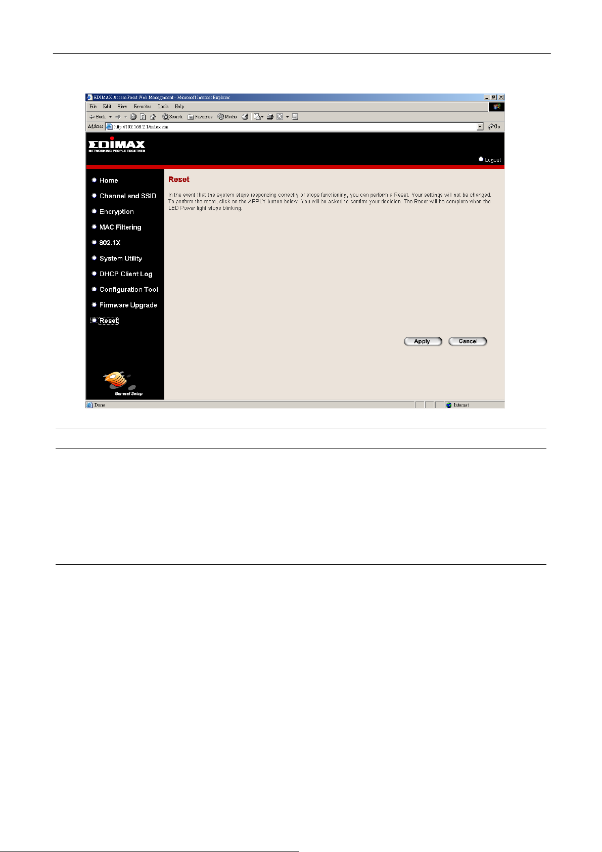
3.2.10 Reset
You can reset the Access Point’s system should any problem exist. The reset function
essentially Re-boots your Access Point’s system.
26
Page 29
Wireless LAN Access Point Configuration
Parameter Description
Reset
In the event that the system stops responding correctly or in some way stops
functioning, you can perform a reset. Your settings will not be changed. To
perform the reset, click on the Apply button. You will be asked to confirm
your decision. The reset will be complete when the power light stops blinking.
Once the reset process is complete you may start using the Access Point
again.
27
Page 30

Troubleshooting
Chapter 4 Troubleshooting
This chapter provides solutions to problems usually encountered during the
installation and operation of the Access Point.
1. How to manually find your PC’s IP and MAC Address?
1) In Windows, open the Command Prompt program
2) Type Ipconfig /all and Enter
Your PC’s IP address is the one entitled IP address
Your PC’s MAC Address is the one entitled Physical Address
2. What is Ad-hoc?
An Ad-hoc wireless LAN is a group of computers, each with a WLAN adapter,
connected as an independent wireless LAN.
3. What is Infrastructure?
An integrated wireless and wired LAN is called an Infrastructure configuration.
4. What is BSS ID?
A group of wireless stations and an Access Point compose a Basic Service Set
(BSS). Computers in a BSS must be configured with the same BSSID.
5. What is ESSID?
An Infrastructure configuration could also support roaming capability for mobile
workers. More than one BSS can be configured as an Extended Service Set (ESS).
Users within an ESS could roam freely between BSSs while maintaining a
continuous connection to the wireless network stations and the Wireless LAN
Access Points.
6. Can data be intercepted while transmitting through the air?
WLAN features two-fold protection in security. On the hardware side, as with
Direct Sequence Spread Spectrum technology, it has the inherent scrambling
security feature. On the software side, the WLAN series offers the encryption
function (WEP) to enhance security and access control.
28
Page 31

Troubleshooting
7. What is WEP?
WEP stands for Wired Equivalent Privacy, a data privacy mechanism based on a
64(40)-bit shared key algorithm.
8. What is a MAC Address?
The Media Access Control (MAC) address is a unique number assigned by the
manufacturer to any Ethernet networking device, such as a network adapter, that
allows the network to identify it at the hardware level. For all practical purposes,
this number is usually permanent. Unlike IP addresses, which can change every
time a computer logs on to the network, the MAC address of a device stays the
same, making it a valuable identifier for the network.
29
 Loading...