


CV-7438nDM
User Manual
06-2013 / v1.0

CONTENTS
I. Product Information .............................................................................. 4
I-1. Package Contents .................................................................................................................. 4
I-2. System Requirements ............................................................................................................ 4
I-3. LED Status .............................................................................................................................. 4
I-4. Rear Panel .............................................................................................................................. 5
I-5. Safety Information ................................................................................................................. 5
II. Installation ............................................................................................ 7
II-1. iQ Setup ................................................................................................................................. 7
II-2. WPS Setup ............................................................................................................................ 11
III. Using the CV-7438nDM ........................................................................ 14
III-1. Ethernet ............................................................................................................................... 14
III-2. Audio Speakers .................................................................................................................... 16
III-2-1. Connecting to your speakers ............................................................................................... 16
III-2-2. Music Streaming .................................................................................................................. 16
III-2-2-1. iTunes & iOS ................................................................................................................. 17
III-2-2-2. Other ............................................................................................................................ 18
III-3. Reset .................................................................................................................................... 21
IV. Browser Based Configuration Interface ................................................. 22
IV-1. Home.................................................................................................................................... 25
IV-2. iQ Setup ............................................................................................................................... 27
IV-3. WPS Settings ........................................................................................................................ 28
IV-4. Wireless Advanced .............................................................................................................. 29
IV-5. Administrator ....................................................................................................................... 32
IV-6. Configuration Tool ............................................................................................................... 35
IV-6-1. Upgrade Firmware ............................................................................................................. 36
IV-6-2. Reboot ............................................................................................................................... 37
V. Appendix ............................................................................................. 39
V-1. Configuring your IP address ............................................................................................... 39
V-1-1. How to configure your computer to use a dynamic IP address ........................................ 40
V-1-1-1. Windows XP ............................................................................................................... 40
V-1-1-2. Windows Vista ........................................................................................................... 41
V-1-1-3. Windows 7 ................................................................................................................. 43
V-1-1-4. Windows 8 ................................................................................................................. 46
V-1-1-5. Mac OS ....................................................................................................................... 49
2

V-1-2. How to modify the IP address of your computer .............................................................. 52
V-1-2-1. Windows XP ............................................................................................................... 52
V-1-2-2. Windows Vista ........................................................................................................... 53
V-1-2-3. Windows 7 ................................................................................................................. 55
V-1-2-4. Windows 8 ................................................................................................................. 59
V-1-2-5. Mac ............................................................................................................................ 63
V-1-3. How to Find Your Network Security Key ........................................................................... 66
V-1-3-1. Windows 7 & Vista ..................................................................................................... 66
V-1-3-2. Mac ............................................................................................................................ 68
V-1-4. How to Find Your Router’s IP Address ............................................................................... 71
V-1-4-1. Windows XP, Vista & 7 ............................................................................................... 71
V-1-4-2. Windows 8 ................................................................................................................. 73
V-1-4-3. Mac ............................................................................................................................ 75
V-1-4. Troubleshooting ................................................................................................................. 78
V-1-5. Glossary.............................................................................................................................. 81
3
I. Product Information
LED Color
LED Status
Description
Red
On
Bridge is powering up or resetting.
Flashing
Bridge is ready to connect to a Wi-Fi
network.
White
On
Bridge is connected to a Wi-Fi network.
Flashing
WPS is active.
Off
-
Bridge is switched off or LED has been
manually disabled.
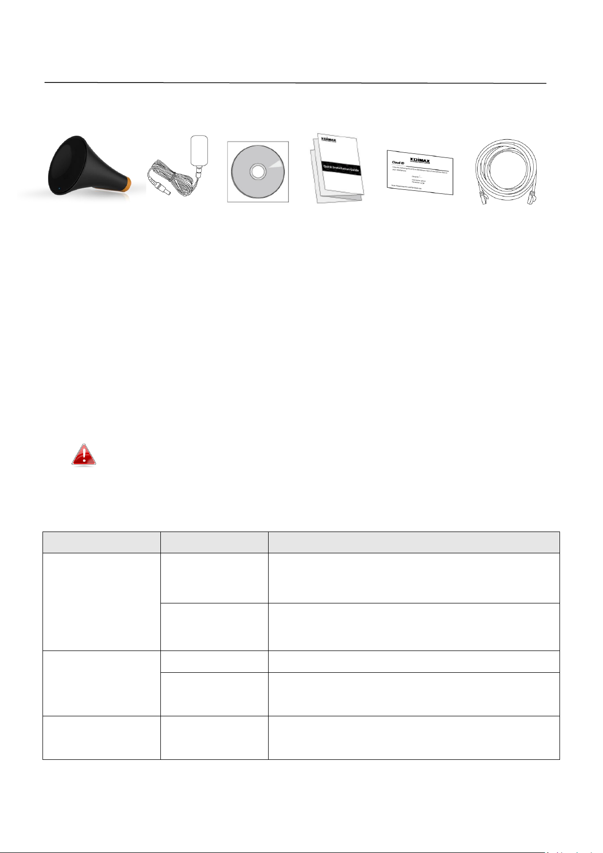
I-1. Package Contents
I-2. System Requirements
- Ethernet-enabled device
- Existing wireless network (2.4GHz or 5GHz)
- Speaker with 3.5mm audio jack for music streaming
- Web browser for software configuration: Microsoft
®
Internet Explorer® 8.0,
Google Chrome®, Firefox® or Safari®, iOS, Android latest version
- iTunes 10.2 or above, iOS 4.3 or above, or 3
rd
party AirPlay streaming app
(recommended: Twonky Beam [requires Android 4.0 or above]).
Please ensure your computer, smartphone, tablet or other device
can support AirPlay streaming.
I-3. LED Status
4
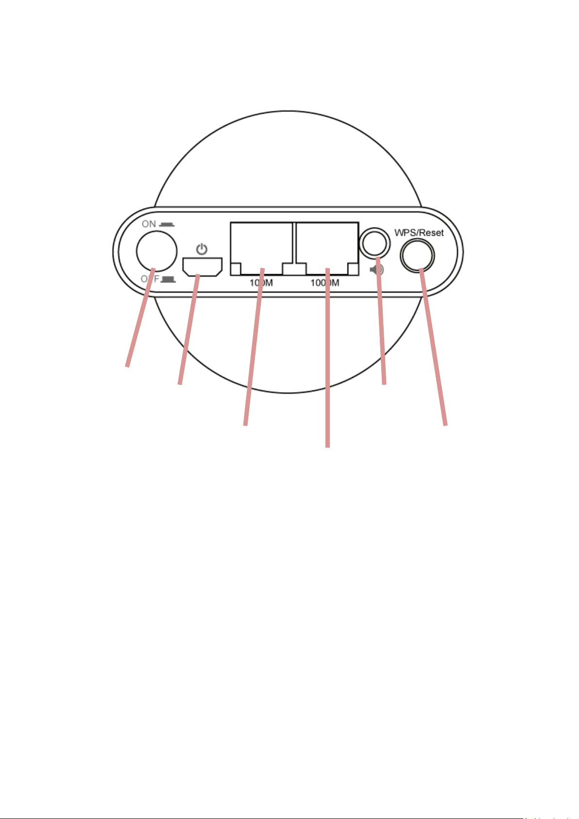
I-3. Rear Panel
Power On/Off
Power Port
100Mbps Port
1000Mbps Port
3.5mm
Audio Jack
WPS/Reset Button
I-5. Safety Information
In order to ensure the safe operation of the device and its users, please read
and act in accordance with the following safety instructions.
1. The wireless bridge is designed for indoor use only; do not place the
wireless bridge outdoors.
2. Do not place the wireless bridge in or near hot/humid places, such as a
kitchen or bathroom.
3. Do not pull any connected cable with force; carefully disconnect it from the
wireless bridge.
4. Handle the wireless bridge with care. Accidental damage will void the
warranty of the wireless bridge.
5

5. The device contains small parts which are a danger to small children under
3 years old. Please keep the wireless bridge out of reach of children.
6. Do not place the wireless bridge on paper, cloth, or other flammable
materials. The wireless bridge may become hot during use.
7. There are no user-serviceable parts inside the wireless bridge. If you
experience problems with the wireless bridge, please contact your dealer of
purchase and ask for help.
8. The wireless bridge is an electrical device and as such, if it becomes wet for
any reason, do not attempt to touch it without switching the power supply
off. Contact an experienced electrical technician for further help.
9. If you smell burning or see smoke coming from the wireless bridge or
power adapter, then disconnect the wireless bridge and power adapter
immediately, as far as it is safely possible to do so. Call your dealer of
purchase for help.
6
II. Installation
There are two ways to setup the wireless bridge. Please follow the
appropriate instructions.
II-1. iQ Setup
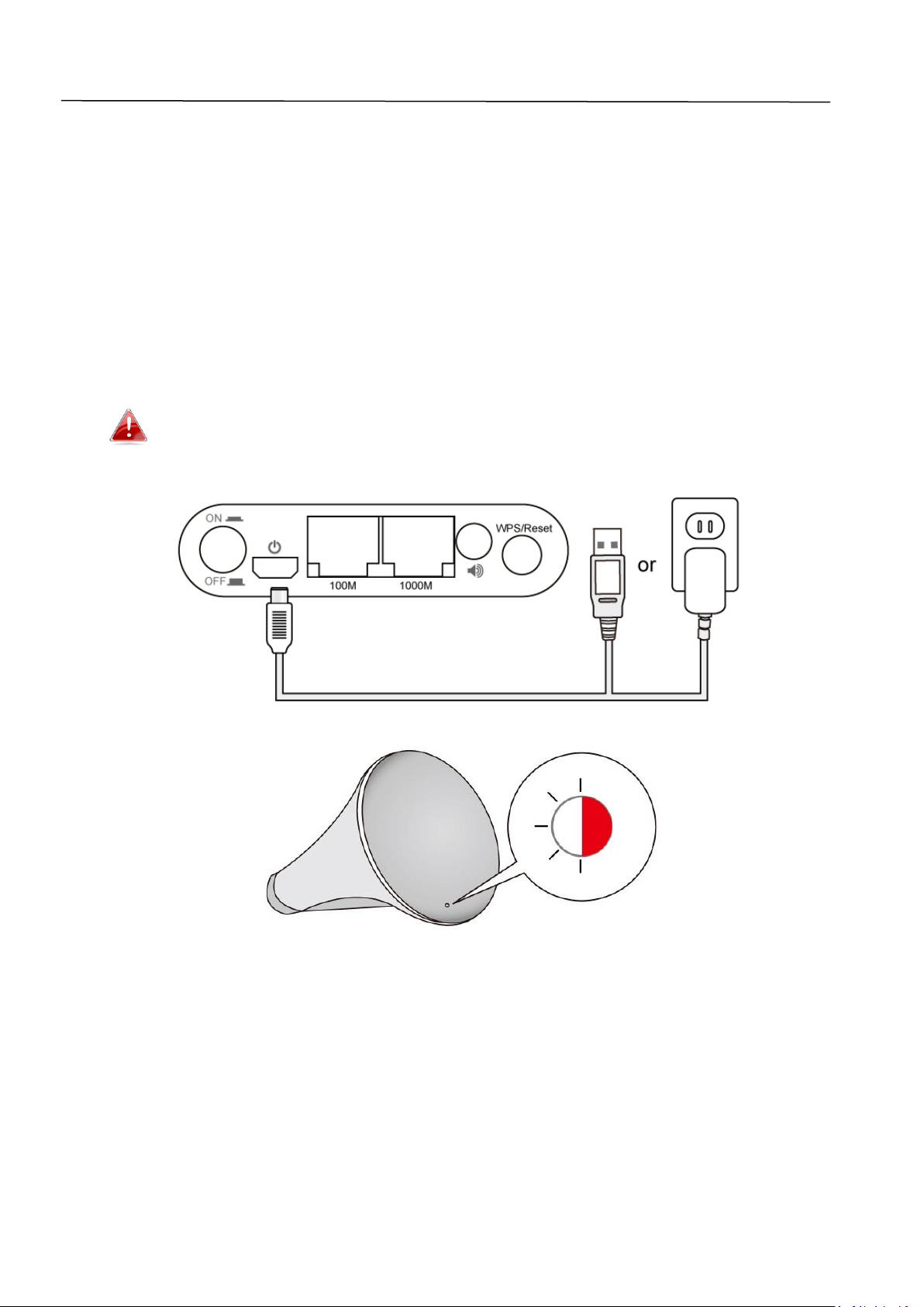
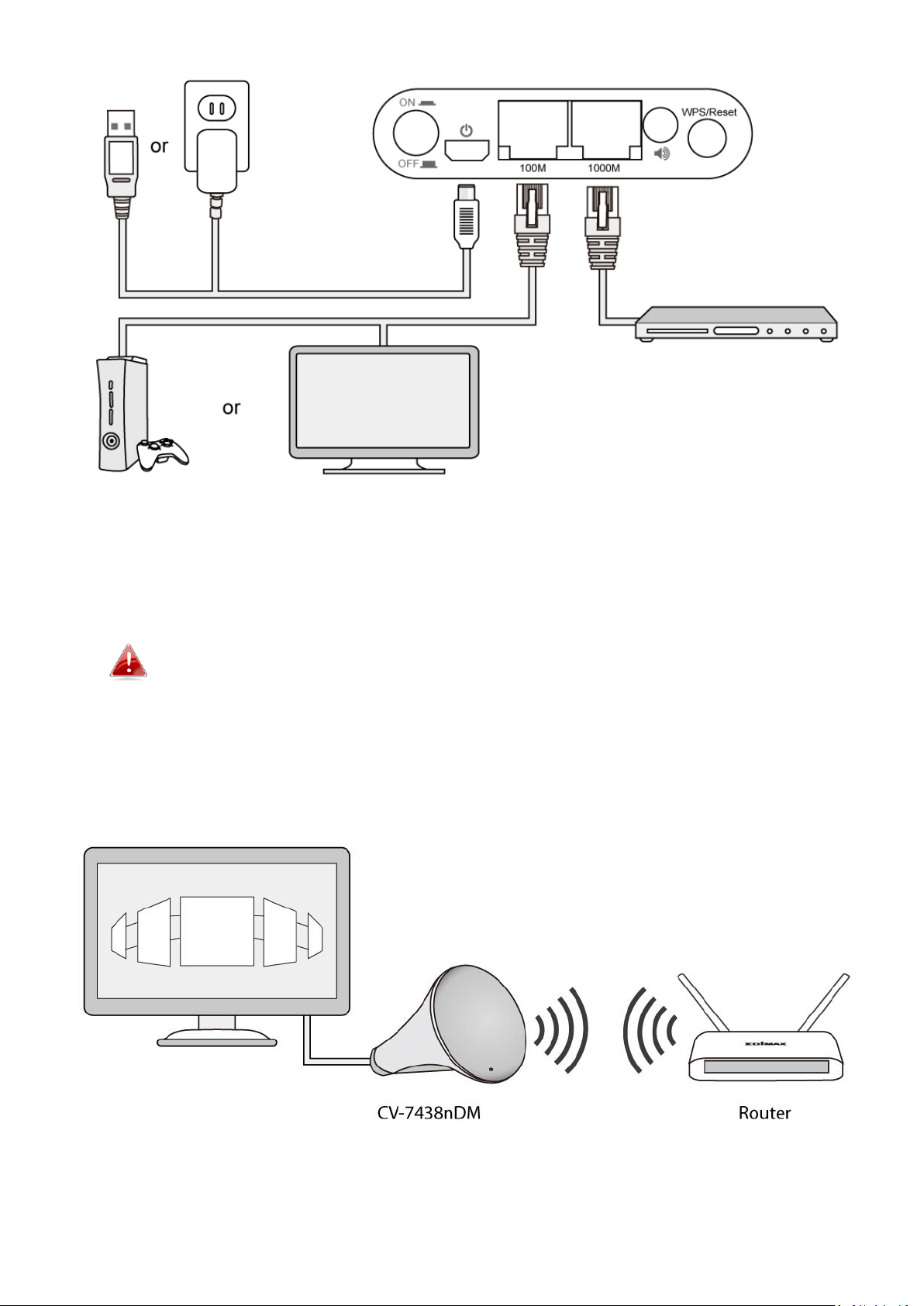
1. Plug the power adapter into the device’s 5V power port, plug the adapter
into a wall socket or available USB port, and press the power on/off button
to switch the device on. The CV-7438nDM may take several minutes to
boot up – the device is ready when the LED is flashing (red).
The CV-7438nDM requires 1 A of current – please ensure that your
USB port can provide sufficient power. If not, use the 5V DC
adapter.
7
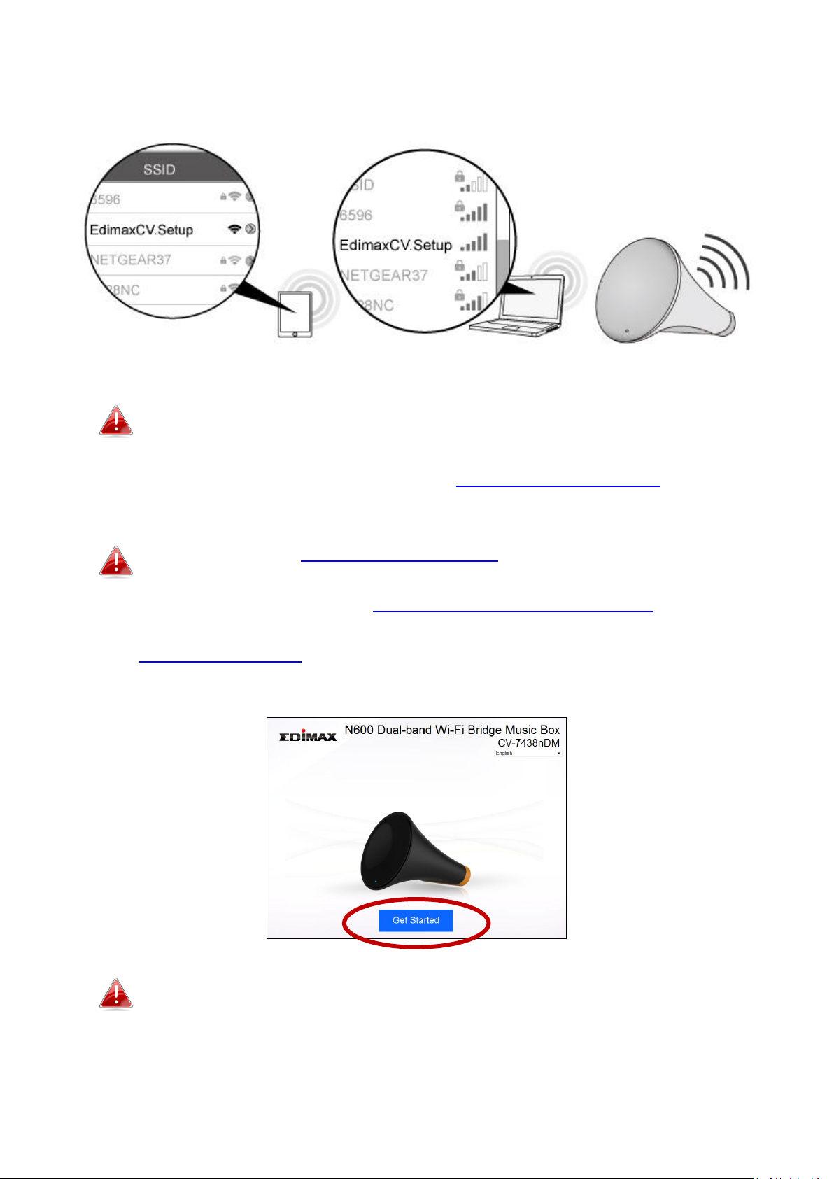
2. Use a Wi-Fi device (e.g. computer, tablet, smartphone) to search for a
Wi-Fi network with the SSID “Edimaxcv.Setup” and connect to it.
Please disconnect any wired Ethernet connections from your
computer before you continue.
3. Open a web browser and enter the URL http://edimaxcv.setup and you
will see the following screen. Please click “Get Started”.
If you can’t access http://edimaxcv.setup please make sure your
wireless device/computer is set to use a dynamic IP address. For
more information, refer to V-1. Configuring your IP address. You
can also use the wireless bridge’s default IP address
http://192.168.9.2 to access the browser based configuration
interface.
You can change the language using the drop down menu in the
top right corner.
8
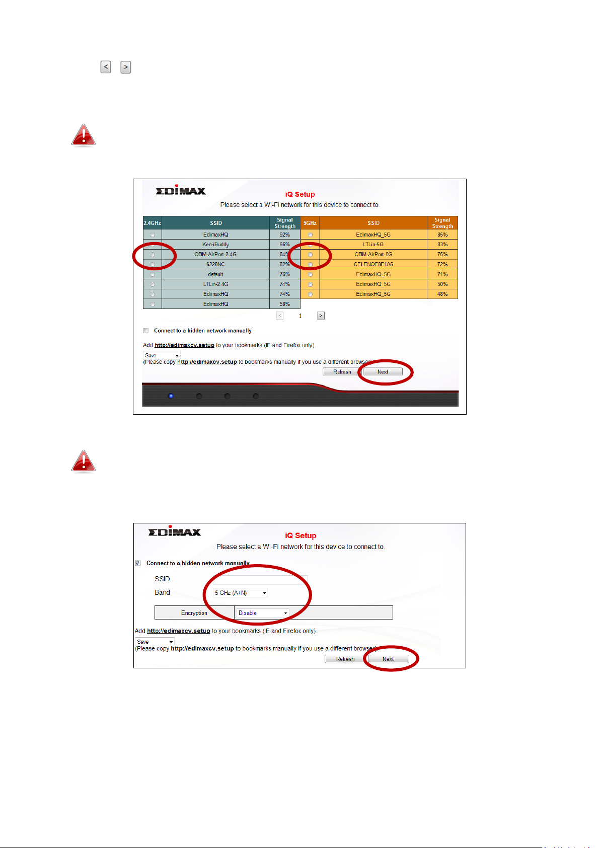
4. iQ Setup will display all available 2.4GHz and 5GHz wireless networks. Click
the icons to display the next or previous page as desired. Select a
network for the wireless bridge to connect to and click “Next”.
If the Wi-Fi network you wish to connect to does not appear, try
clicking “Refresh”.
If you use a hidden network, to connect to a hidden SSID, check
the “Connect to a hidden network manually” box and enter the
SSID and security key information.
9
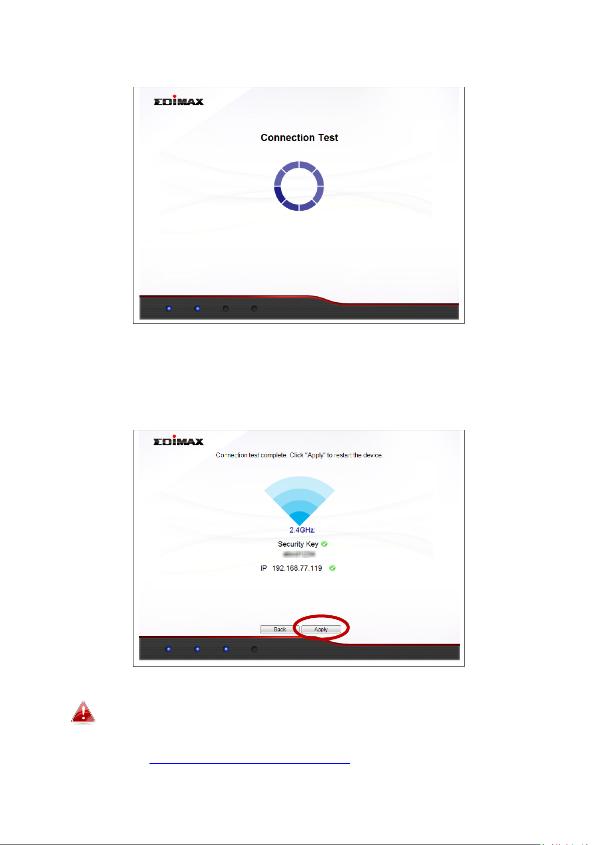
5. Please wait while the wireless bridge tests the connection.
6. When the connection test is complete, you will see the following screen.
Check the details of your connection and click “Apply” to restart the
CV-7438nDM and continue.
If the wireless bridge cannot obtain an IP address from the
router/access point then click the “Static IP” button to assign an
IP address to the wireless bridge and then click “APPLY”. Please
refer to V-1. Configuring your IP address for more guidance.
10

7. A congratulations screen will confirm your wireless bridge has established
a connection.
If you do not see the congratulations screen shown above, check
the LED: if the LED displays on (white) then the wireless bridge
has successfully established a connection. Continue to III. Using
the CV-7438nDM.
When the Wi-Fi bridge’s LED displays on (white), the wireless bridge is now ready
for use with audio speakers or Ethernet devices such as smart TVs, set-top boxes or
game consoles. Please see III. Using the CV-7438nDM.
II-2. WPS Setup
WPS setup is an alternative to II-1. iQ Setup. If you already
completed iQ Setup, please continue to III. Using the CV-7438nDM.
The WPS button is a quick and easy method to establish a secure connection
between your wireless bridge and wireless router/access point. The wireless
bridge can connect to either 2.4GHz or 5GHz Wi-Fi networks via WPS,
depending on which frequency’s WPS is active on your wireless router/access
point.
1. Plug the power adapter into the device’s 5V power port, plug the adapter
into a wall socket or available USB port, and press the power on/off button
to switch the device on. The CV-7438nDM may take several minutes to
boot up – the device is ready when the LED is flashing (red).
The CV-7438nDM requires 1 A of current – please ensure that your
USB port can provide sufficient power. If not, use the 5V DC
adapter.
11
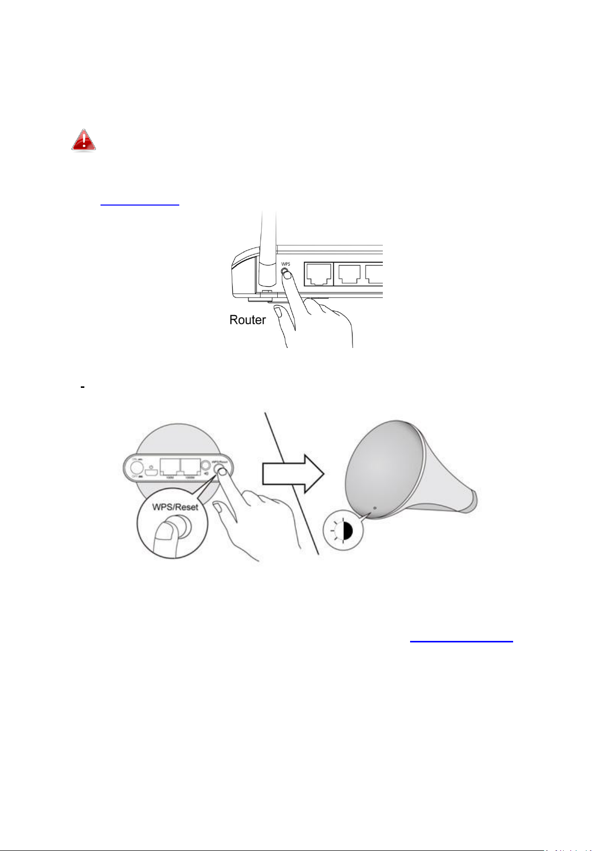
2. Press and hold the WPS button on your wireless router/access point for
the correct length of time to activate its WPS.
Please check the instructions for your wireless router/access point
to confirm how long you need to hold down its WPS button to
activate WPS for 2.4GHz or 5GHz. Some brands of router/access
point may not support WPS for 5GHz – in this case, please refer to
II-1. iQ Setup instead.
3. Within two minutes, press and hold the WPS button on the CV-7438nDM
for 2 seconds to activate the WPS function. The LED should flash (white) to
indicate that WPS is in progress.
4. The devices will establish a connection. When a connection is successful,
the bridge’s LED will display on (white). If a connection is not successful,
the LED will flash (red) – in this case please return to II-2. WPS Setup Step
1.
12

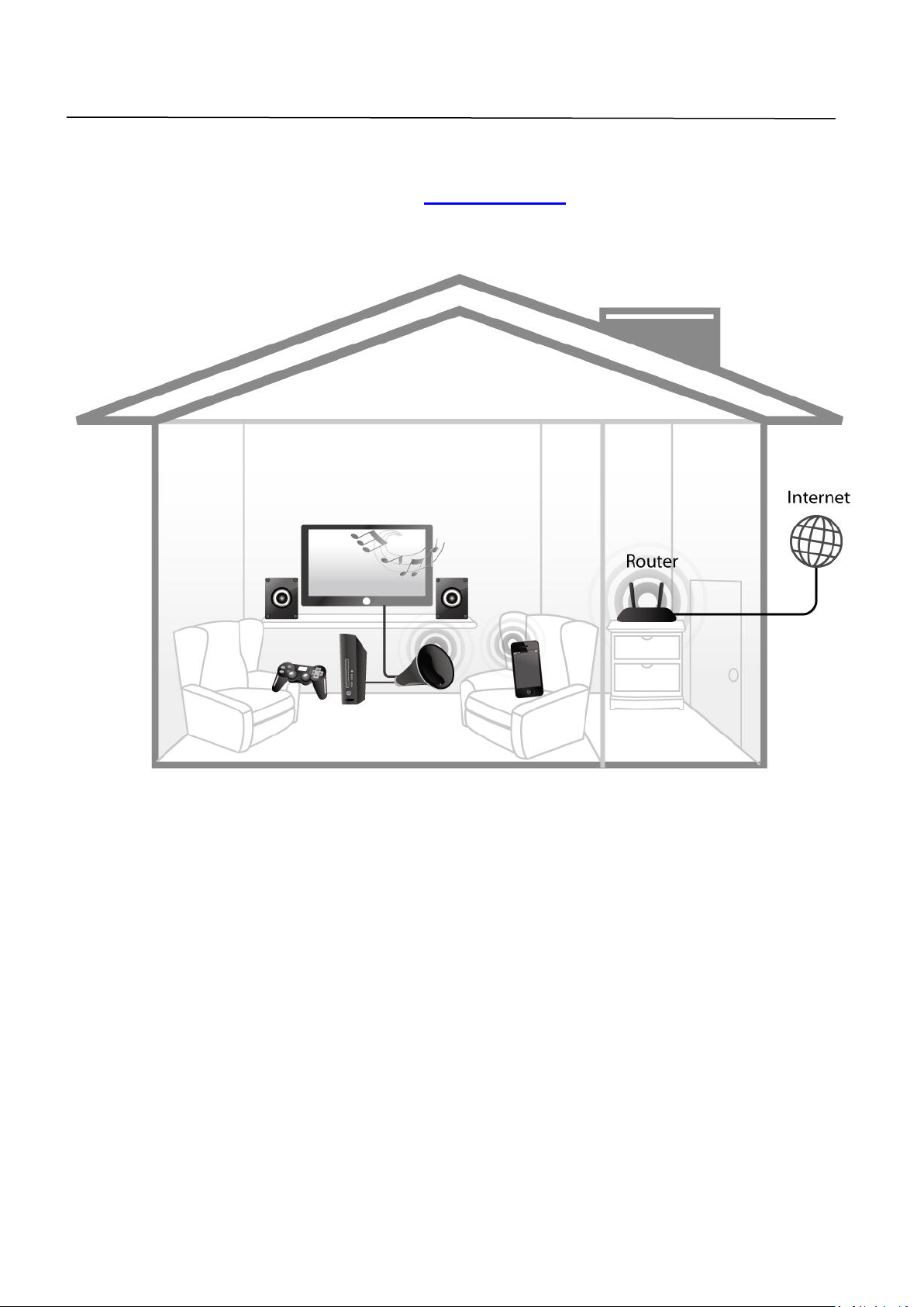
Your wireless bridge is now ready for use with audio speakers or Ethernet
devices such as smart TVs, set-top boxes or game consoles. Please see III.
Using the CV-7438nDM.
13
III. Using the CV-7438nDM
Once your CV-7438nDM has established a connection with your wireless
router/access point as described in II. Installation, you can connect the
wireless bridge to any Ethernet device or audio speakers for wireless
connectivity.
III-1. Ethernet
To “bridge” any Ethernet device to your Wi-Fi network, follow the instructions
below.
1. Use an Ethernet cable to connect the Wi-Fi bridge to the Ethernet port on
your network device. You can use either of the Wi-Fi bridge’s Ethernet
ports (10/100 or 10/100/1000) depending on your requirements.
14
2. Connect the CV-7438nDM’s power supply to a wall socket or an available
USB port, and press the power on/off button to switch the device on.
Ensure the LED is on (white).
The CV-7438nDM requires 1 A of current – please ensure that your
USB port can provide sufficient power. If not, use the 5V DC
adapter.
3. Switch on your network device and connect to your network as usual for a
wired Ethernet connection.
15
III-2. Audio Speakers
You can use the wireless bridge to “bridge” any audio speakers to your Wi-Fi
network via a 3.5mm audio jack.
III-2-1. Connecting to your speakers
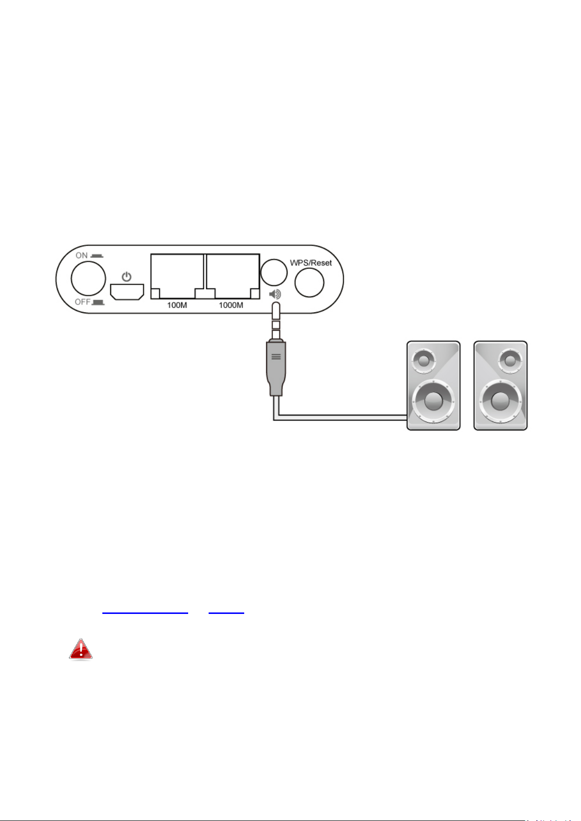
1. Use an audio cable (not included) to connect the Wi-Fi bridge’s 3.5mm
audio jack to the “audio in” port of your speakers.
2. Connect the CV-7438nDM’s power supply to a wall socket or an available
USB port, and press the power on/off button to switch the device on.
Ensure the LED is on (white).
III-2-2. Music Streaming
After the wireless bridge is correctly connected to your speakers, you can
stream music to your speakers wirelessly. Follow the appropriate instructions
below for iTunes & iOS or other users.
Ensure that your music player (e.g. PC, tablet or smartphone) is
connected to the same router as your CV-7438nDM.
16
III-2-2-1. iTunes & iOS
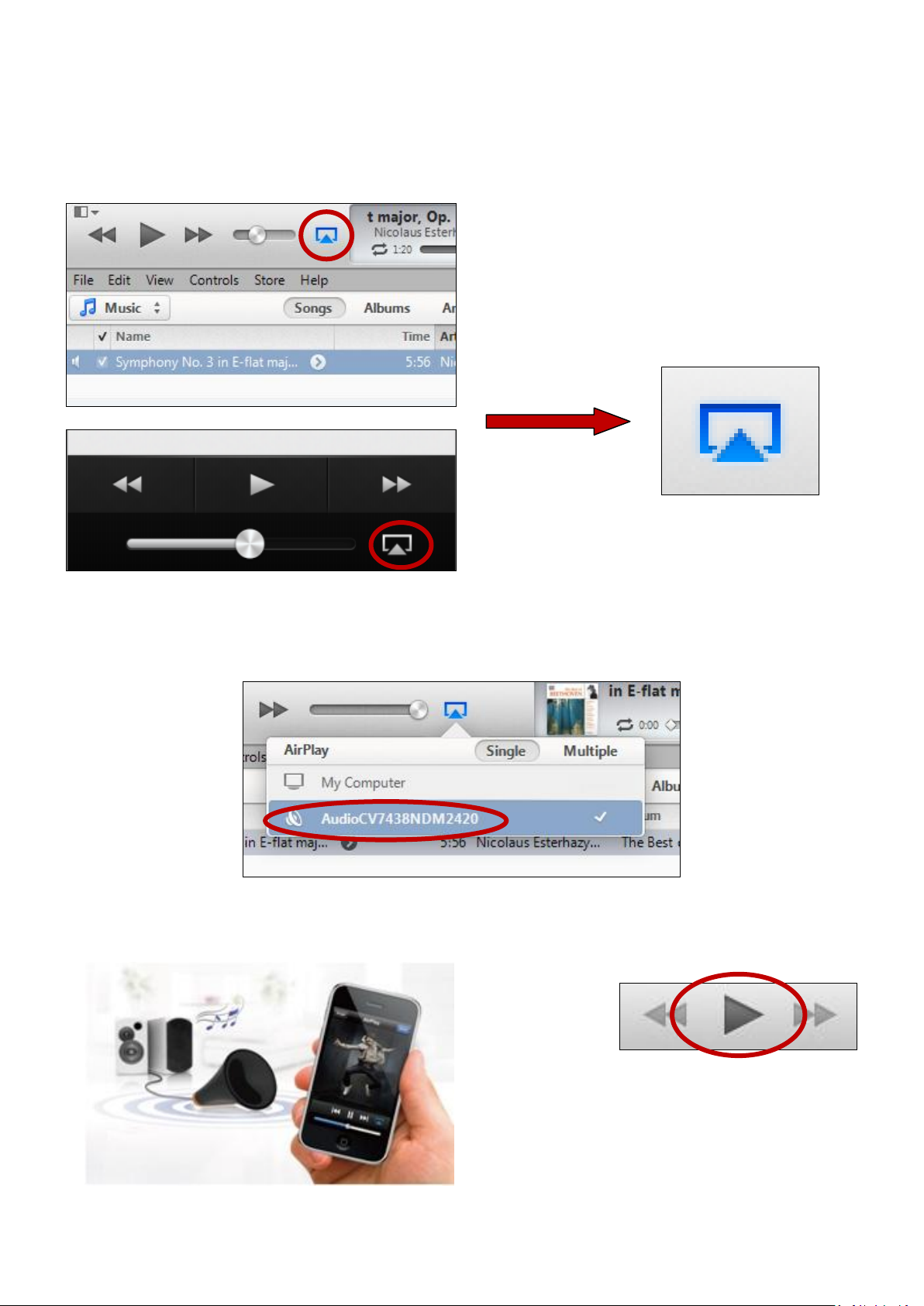
1. Click the AirPlay icon in iTunes.
2. Select the CV-7438nDM from the list of available AirPlay devices.
3. Play music as usual and it should stream to your speakers wirelessly.
17
III-2-2-2. Other
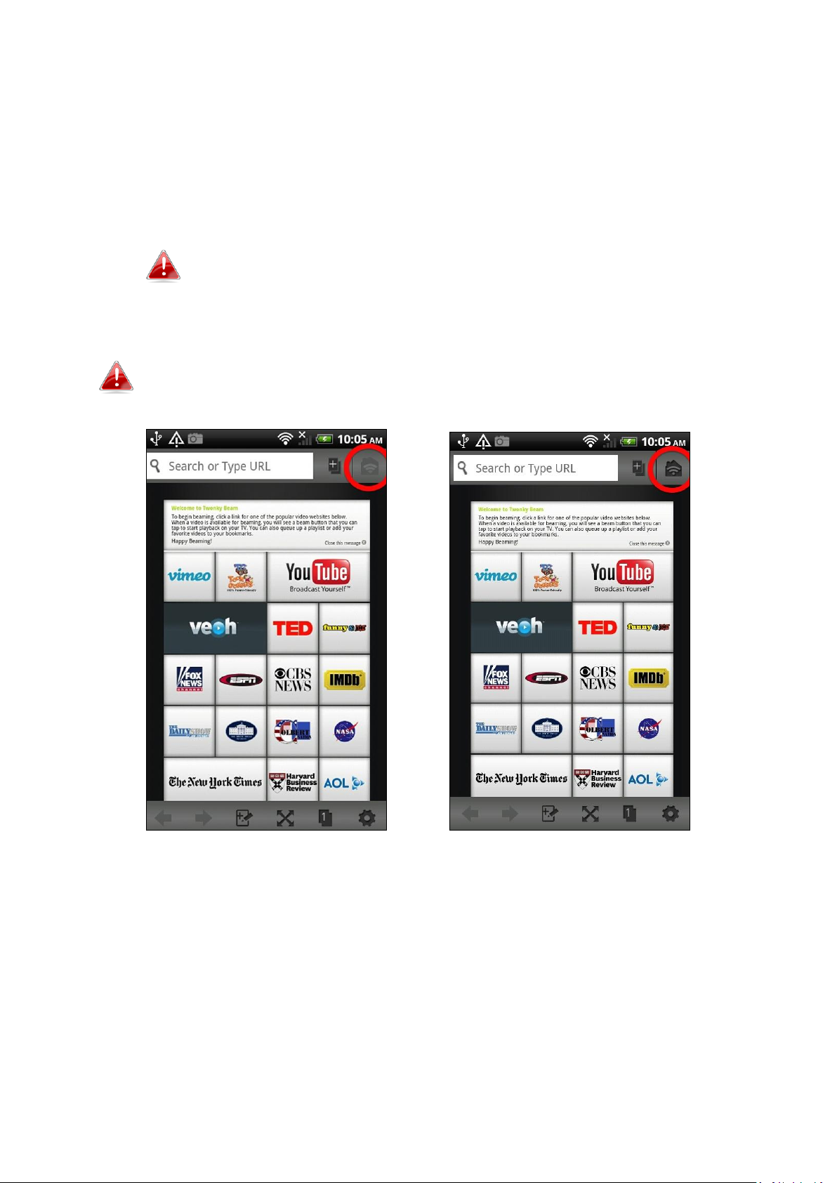
For other users (Android, PC) a 3rd party app is necessary to facilitate AirPlay
streaming. Apps such as Twonky Beam for Android offer AirPlay streaming
functionality and can be downloaded from Google Play. An example of AirPlay
streaming using Twonky Beam is shown below:
Twonky Beam requires Android OS 4.0 or above device.
1. Wait for the icon in the top right corner to light up and then tap it.
Depending on your Internet connection, the icon may take several
minutes to light up.
18
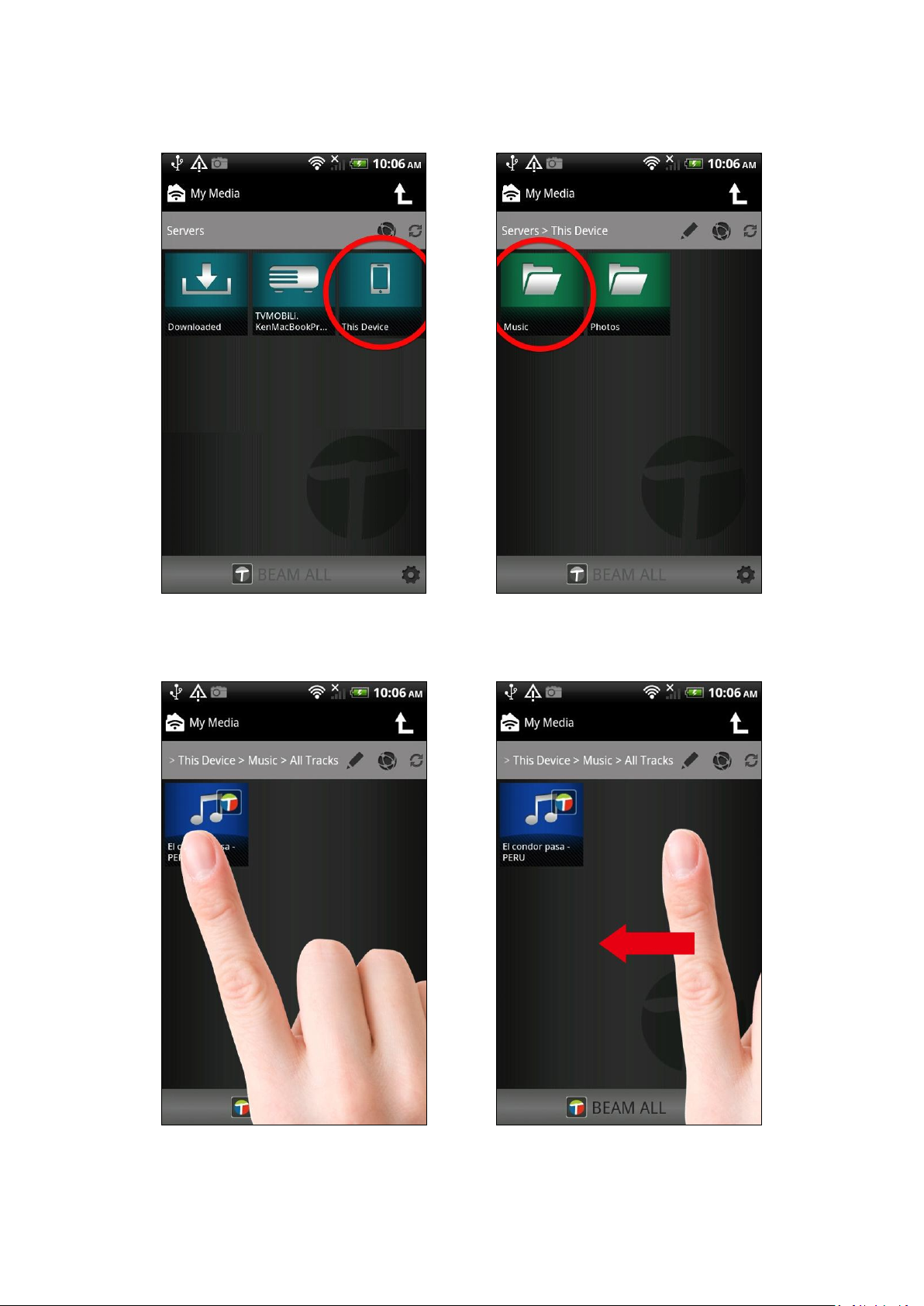
2. On the next screen, select “This Device” and then select “Music”.
3. Select a track and then swipe the screen right to left.
19
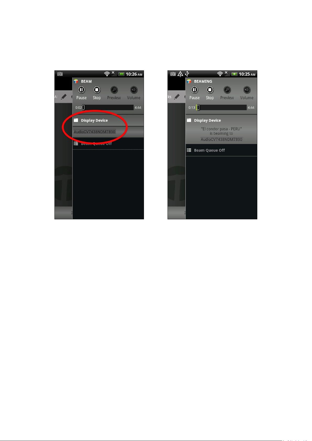
4. You should see the CV-7438nDM listed as a “Display Device” amongst any
other wireless displays or speakers connected to your network. Select the
CV-7438nDM as the “Display Device”.
5. Your music should stream wirelessly to the speakers connected to the
CV-7438nDM.
20
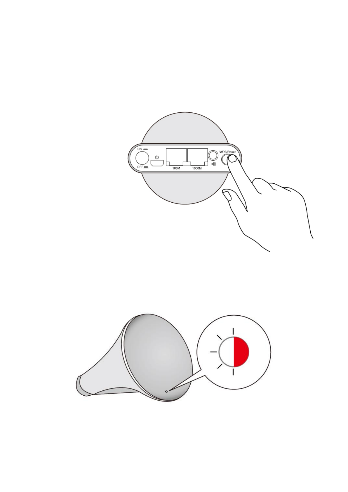
III-3. Reset
If you experience problems with your wireless bridge, you can reset the device
back to its factory settings. This resets all settings back to default.
1. Press and hold the WPS/Reset button found on the back panel for at least
10 seconds.
2. Release the button when the LED displays on (red).
3. Wait for the wireless bridge to restart. The wireless bridge is ready for
setup when the LED is flashing (red).
21
IV. Browser Based Configuration Interface
After you have setup the wireless bridge as detailed in II. Installation or the
included QIG, you can further configure the settings of the wireless bridge,
using the browser based configuration interface.
A computer is required to access the browser based configuration
interface after initial setup. Smartphones and tablets cannot
access the browser based configuration interface.
Please ensure that your computer is set to use a dyanmic IP
address. Refer to Appendix V-1. Configuring your IP Address for
more information.
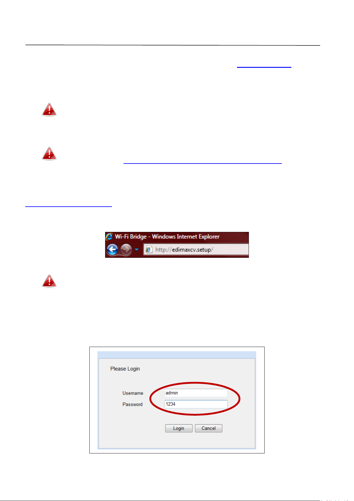
To access the browser based configuration interface enter
http://edimaxcv.setup into the URL bar of a browser on a network device
connected to the same Wi-Fi network as the wireless bridge.
If you can not access the browser based configuration following
the instructions below, connect the CV-7438nDM to a computer
using an Ethernet cable and try again.
You will be prompted for a username and password. The default username is
“admin” and the default password is “1234”.
22
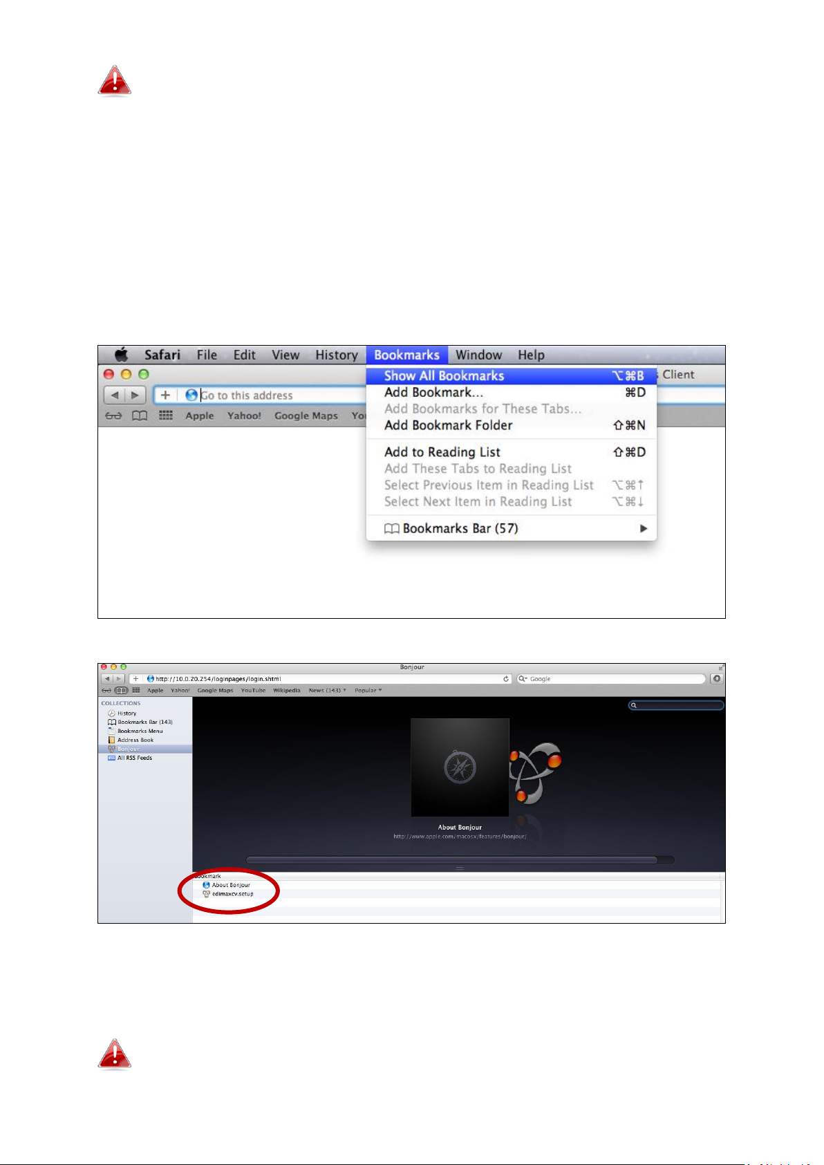
Mac users can also use the “Bonjour” function of Safari to access
the browser based configuration interface.
Mac: Bonjour
Open Safari web browser and open the “Bookmarks” menu across the top of
the screen, and select “Show All Bookmarks”. Or you can click on the
bookmarks icon under the URL bar.
Then, select “Bonjour” from the menu in the left panel. Finally, click on
“edimaxcv.setup” in the lower panel on the right side.
You will arrive at the “Home” screen shown below. Use the menu down the
left side to navigate.
You can change the language using the drop-down menu in the
top right corner.
23
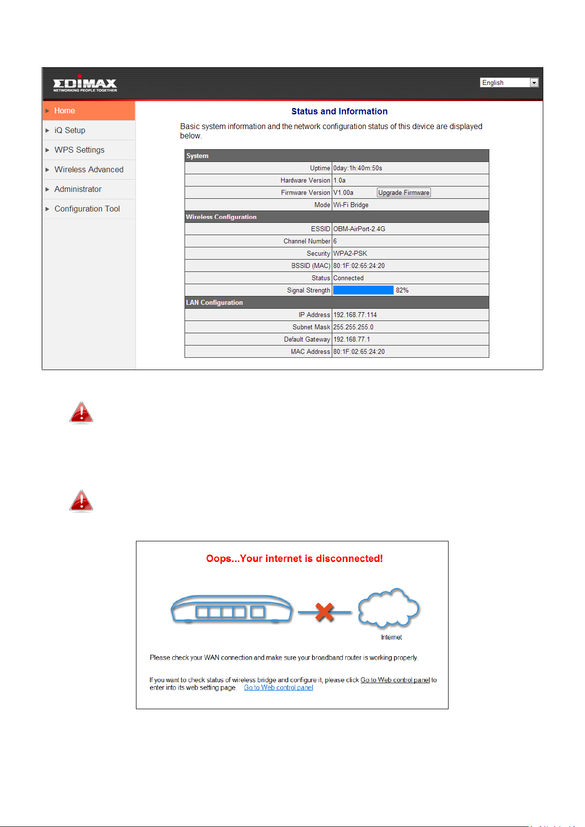
If you see the screen below, there is a problem with your wireless
bridge’s WAN connection. Please check your WAN connection.
Click “Go to Web control panel” to continue to the browser based
configuration interface.
The wireless bridge will not function properly without a WAN
connection.
24
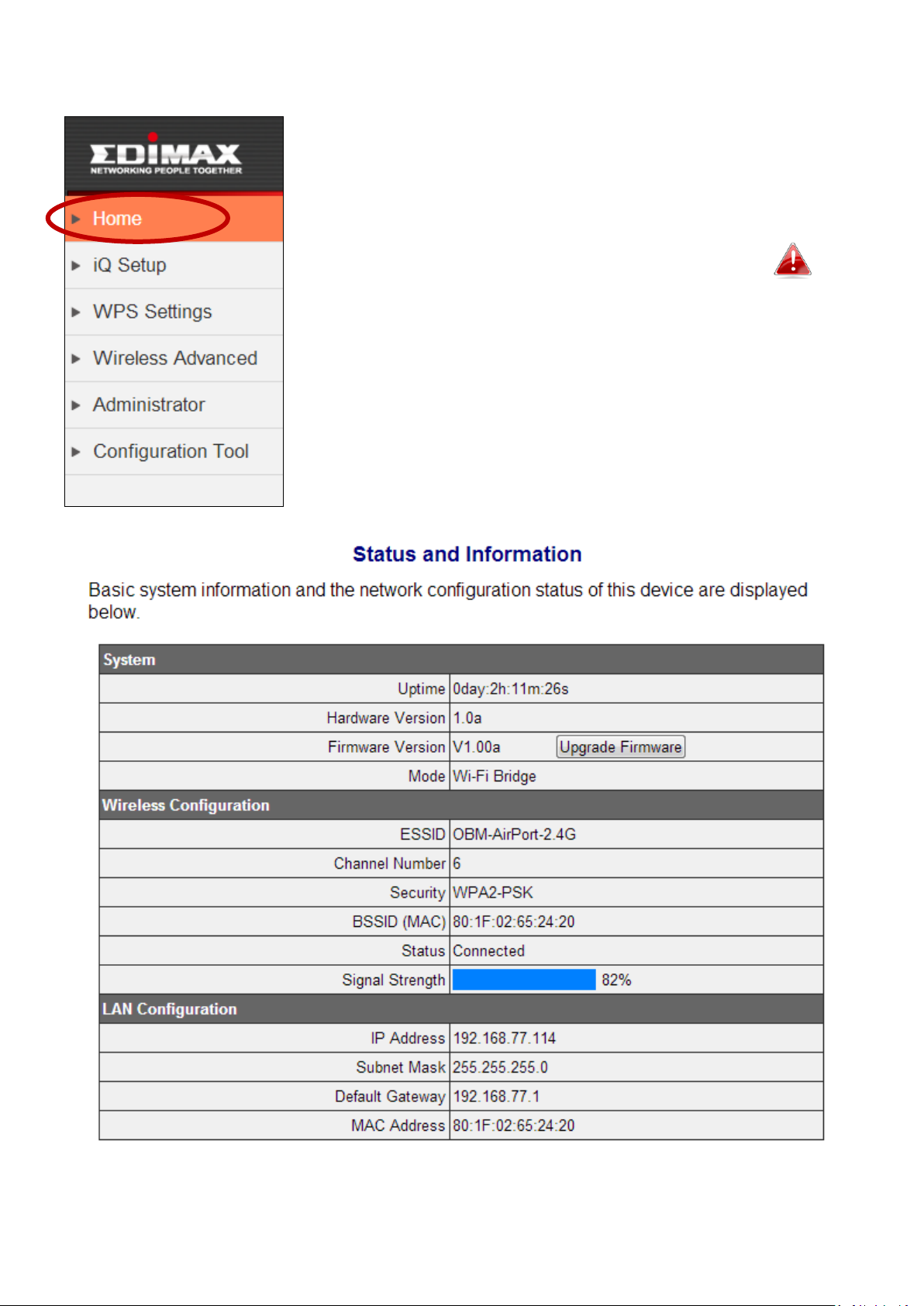
IV-1. Home
The “Home” page displays basic system information
about the wireless bridge.
Screenshots displayed are examples. The
information shown on your screen will vary
depending on your configuration.
25

Uptime
Displays the total time since the device was
turned on.
Hardware
Version
Displays the hardware version.
Firmware
Version
Displays the firmware version.
Mode
Displays the operating mode.
ESSID
Displays the ESSID the wireless bridge is
connected to. The ESSID is the name used
to identify a wireless network.
Channel
Number
Displays the current wireless channel
number.
Security
Displays the current wireless security
setting.
BSSID (MAC)
Displays the device’s BSSID. The BSSID
identifies this wireless bridge in the
network, and is the same as the device’s
MAC address.
Status
Displays the current status of the wireless
bridge.
Signal Strength
Displays the wireless signal strength.
IP Address
Displays the IP address of this device.
Subnet Mask
Displays the subnet mask of the IP address.
Default
Gateway
Displays the IP address of the default
gateway.
MAC address
Displays the device’s MAC address. The
MAC address is a unique, fixed ID for this
device, it cannot be modified.
26
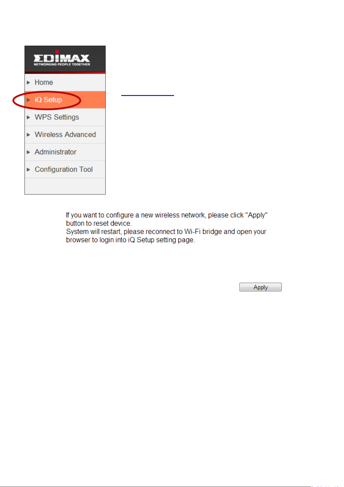
IV-2. iQ Setup
You can run iQ Setup again to reconfigure the wireless
bridge. Click “Apply” to reset the wireless bridge back
to its factory default, unconfigured state. Then connect
to the “EdimaxCV.setup” SSID to start iQ Setup. Refer
to II. Installation for guidance on iQ Setup.
27

Enable WPS
Check/uncheck this box to enable/disable
WPS
IV-3. WPS Settings
Wi-Fi Protected Setup is a simple way to establish
connections between WPS compatible devices. WPS
can be activated on compatible devices by pushing a
WPS button on the device or from within the device’s
firmware/configuration interface. When WPS is
activated in the correct manner and at the correct time
for two compatible devices, they will automatically
connect. PIN code WPS includes the use of a PIN code
between the two devices for verification.
The “WPS Settings” page displays information
regarding WPS.
It is recommended to configure data encryption/security settings
on your router/access point before using WPS.
28

WPS Status
Displays WPS status. If data
encryption/security settings for the wireless
bridge’s SSID have never been set,
“unConfigured” will be shown here. If data
encryption/security settings for the wireless
bridge’s SSID have been set, “Configured”
will be shown here.
Device PIN Code
Displays the WPS PIN code of the wireless
bridge.
(Client Device)
Configuration
Mode
“Enrollee” mode means the wireless
bridge will follow the wireless settings of
wireless router/access point for WPS
connections. “Enrollee” mode is fixed and
cannot be modified.
Configure via
Push Button
Click “Start PBC” (Push-Button
Configuration) to activate WPS on the
wireless bridge. WPS will be active for 2
minutes. The LED on the wireless bridge will
flash (white) while WPS is active.
Send PIN Code
to AP/Router
The wireless bridge’s WPS PIN code is
displayed here. Click “Send PIN” to
automatically send the PIN to the
router/access point.
IV-4. Wireless Advanced
In “Wireless Advanced” you can configure advanced
wireless settings. Please do not modify these settings
unless you are sure what effect the changes will have
on your wireless bridge; advanced settings are for
experienced users only.
Changing these settings can adversely affect the
performance of your wireless bridge.
29

Fragment
Threshold
Set the Fragment threshold of the wireless
radio. The default value is 2346.
RTS Threshold
Set the RTS threshold of the wireless radio.
The default value is 2347.
WMM
WMM (Wi-Fi Multimedia) technology can
improve the performance of certain
network applications, such as audio/video
streaming, network telephony (VoIP), and
others. When you enable WMM, the
wireless bridge will define the priority of
different kinds of data, to give higher
priority to applications which require
instant responses and improve
performance. WNM is enabled by default.
TX Power
Adjust the output power of the wireless
radio. You may not require 100% output
power.
Enable LED Off
Mode
Check/uncheck this box to enable/disable
“LED Off Mode”. Select “Turn off all LED
indicators” to disable the LED on the
wireless bridge.
Click “Apply” to save and apply the changes, or click “Cancel” to discard
changes.
30

31

IV-5. Administrator
In “Administrator” you can change the login
information for your wireless bridge, which you use to
access the browser based configuration interface.
Additionally, you can modify the IP address of the
wireless bridge.
If you change the administrator password, please
make a note of the new password. In the event
that you forget this password and are unable to
login to the browser based configuration interface,
see III-3. Reset for how to reset the wireless bridge.
32

Current
Password
Enter your current password. The default
password is 1234.
New Password
Enter your desired new password here. You
can use any combination of letters,
numbers and symbols up to 20 characters.
Re-Enter
Password
Confirm your new password.
IP Address
Specify an IP address here. This IP address
will be assigned to wireless bridge.
Subnet Mask
Input the subnet mask of the new IP
address.
Gateway
Address
Input the network’s gateway IP address.
You can modify the IP address of the wireless bridge, enabling it to become a
part of your local area network.
Please write down and remember the new IP address you
assigned to the wireless bridge. If you forget this IP address you
may not be able to connect to the browser based configuration
interface in the future.
For static IP users, the wireless bridge needs to have an IP address
in the same subnet as your network, in order that you can access
iQ Setup/browser based configuration interface. For example, if
your static IP is 192.168.9.2 then you need to assign the wireless
bridge an IP address in the range 192.168.9.x where x = 3-254.
Each network device has a unique IP address.
To ensure that you assign a correct IP address to the wireless
bridge, you can also check the IP address of your router. Please
refer to V-1-4. How to Find Your Router’s IP Address. Your ISP can
also provide you with such information as IP address, subnet
mask and gateway address.
33

If you are unable to connect to the browser based configuration
interface using http://edimaxcv.setup, it is possible that you
assigned an incorrect IP address to the wireless bridge. In this
case you can reset the wireless bridge back to its default IP
address. See III-3. Reset.
Click “Apply” to save and apply the changes, or click “Cancel” to discard
changes.
34

IV-6. Configuration Tool
Backup Settings
Click “Save” to save the current settings on
your computer as a config.bin file.
Restore Settings
Click the browse button to locate a
previously saved config.bin file and then
click “Upload” to upload the file and replace
your current settings.
Restore to
Factory Defaults
Click “Reset” to restore settings to the
factory default. A status bar will indicate the
On the “Configuration Tool” page you can back up the
wireless bridge’s current settings, restore the settings
to a previously saved version or restore the wireless
bridge back to its original factory default state.
restore all settings, configurations and passwords
back to the factory default It is recommended that
you backup your existing settings before restoring
Restoring settings to the factory default will
to factory defaults.
35

progress of the restore and you will see a
confirmation screen when the reset is
complete.
After restoring to the bridge to factory defaults, you will need to
connect to the “EdimaxCV.setup” SSID again and setup the
wireless bridge. See II. Installation.
You can also restore the wireless bridge to its factory default
state by pressing and holding the WPS/Reset button for at least
10 seconds. The LED will display on (red) while the device resets.
The wireless bridge is ready when the LED is flashing (red).
IV-6-1. Upgrade Firmware
Selecting “Firmware upgrade” from the “Configuration
Tool” menu allows you to update the system firmware
to a more recent version. You can download the latest
firmware from the Edimax website.
Do not switch off or disconnect the wireless bridge
during a firmware upgrade, as this could damage
the device.
It is recommended to use a wired Ethernet
connection to upload a firmware file.
36

Choose File
Click “Choose File” to open a new window,
locate a firmware file on your computer,
and confirm your selection.
Click “Apply” to save and apply the changes, or click “Cancel” to discard
changes.
IV-6-2. Reboot
If the wireless bridge malfunctions or is not responding,
then it is recommended that you reboot the device.
You can reboot the bridge from this page remotely
(below) if the location of the wireless bridge is not
convenient, or you can switch the device off and back
on again using the on/off switch located on the back of
the device.
Rebooting the wireless bridge will not affect the
current configuration and settings of the device.
37

Apply
Click “Apply” to reboot the device. A status
bar will indicate the progress of the reboot
and you will see a confirmation screen
when the reboot is complete.
38

V. Appendix
V-1. Configuring your IP address
Before you run iQ Setup, please make sure your computer is set to use a
dynamic IP address. This means your computer can obtain an IP address
automatically from a DHCP server. This is a simple procedure, which is
explained step by step in V-1-1. How to configure your computer to use a
dynamic IP address.
Static IP users can run iQ Setup by a) temporarily switching to a dynamic IP
address or b) modifying the static IP address of your computer.
For b) the wireless bridge uses the default IP address 192.168.9.2 so you need
to modify your computer’s IP address to be in the same IP address subnet e.g.
192.168.9.x (x = 10 – 254).
Static IP users please make a note of your static IP before you
change it or switch to a dynamic IP address.
The procedure for modifying your IP address varies across different operating
systems; please follow the guide appropriate for your operating system in
V-1-2. How to modify the IP address of your computer
You can assign a new IP address to the wireless bridge which is within the
subnet of your network during iQ Setup, or after iQ Setup using the browser
based configuration interface (refer to IV-5. Administrator). Please change
your IP address back to its original value after the wireless bridge is properly
configured.
39

V-1-1. How to configure your computer to use a dynamic IP address
Please follow the instructions appropriate for your operating system.
V-1-1-1. Windows XP
1. Click the “Start” button (it should be located in the lower-left corner of
your computer), then click “Control Panel”. Double-click the “Network and
Internet Connections” icon, click “Network Connections”, and then
double-click “Local Area Connection”. The “Local Area Connection Status”
window will then appear, click “Properties”.
2. Select “Obtain an IP address automatically” and “Obtain DNS server
address automatically”, then click “OK”.
40

V-1-1-2. Windows Vista
1. Click the “Start” button (it should be located in the lower-left corner of
your computer), then click “Control Panel”. Click “View Network Status and
Tasks”, then click “Manage Network Connections”. Right-click “Local Area
Network”, then select “Properties”. The “Local Area Connection Properties”
window will then appear, select “Internet Protocol Version 4 (TCP / IPv4)”,
and then click “Properties”.
41

2. Select “Obtain an IP address automatically” and “Obtain DNS server
address automatically”, then click “OK”.
42

V-1-1-3. Windows 7
1. Click the “Start” button (it should be located in the lower-left corner of
your computer), then click “Control Panel”.
2. Under “Network and Internet” click “View network status and tasks”.
3. Click “Local Area Connection”.
43

4. Click “Properties”.
5. Select “Internet Protocol Version 4 (TCP/IPv4) and then click “Properties”.
44

6. Select “Obtain an IP address automatically” and “Obtain DNS server
address automatically”, then click “OK”.
45

V-1-1-4. Windows 8
1. From the Windows 8 Start screen, you need to switch to desktop mode.
Move your curser to the bottom left of the screen and click.
2. In desktop mode, click the File Explorer icon in the bottom left of the
screen, as shown below.
46

3. Right click “Network” and then select “Properties”.
4. In the window that opens, select “Change adapter settings” from the left
side.
47

5. Choose your connection and right click, then select “Properties”.
6. Select “Internet Protocol Version 4 (TCP/IPv4) and then click “Properties”.
48

7. Select “Obtain an IP address automatically” and “Obtain DNS server
address automatically”, then click “OK”.
V-1-1-5. Mac OS
1. Have your Macintosh computer operate as usual, and click on “System
Preferences”.
2. In System Preferences, click on “Network”.
3. Click on “Wi-Fi” in the left panel and then click “Advanced” in the lower
right corner.
49

4. Select “TCP/IP” from the top menu and select “Using DHCP” from the
drop down menu labeled “Configure IPv4”, then click “OK”.
5. Click on “Apply” to save the changes.
50

51

V-1-2. How to modify the IP address of your computer
Please follow the instructions appropriate for your operating system. In the
following examples we use the IP address 192.168.9.20 though you can use
any IP address in the range 192.168.9.x (x = 3 – 254) in order to access iQ
Setup/browser based configuration interface.
Please make a note of your static IP before you change it.
V-1-2-1. Windows XP
1. Click the “Start” button (it should be located in the lower-left corner of
your computer), then click “Control Panel”. Double-click the “Network and
Internet Connections” icon, click “Network Connections”, and then
double-click “Local Area Connection”. The “Local Area Connection Status”
window will then appear, click “Properties”.
2. Select “Use the following IP address”, then input the following values:
Your existing static IP address will be displayed in the “IP
address” field before you replace it. Please make a note of this IP
52

address, subnet mask, default gateway and DNS server
addresses.
IP address: 192.168.9.20
Subnet Mask: 255.255.255.0
Click ‘OK’ when finished.
V-1-2-2. Windows Vista
1. Click the “Start” button (it should be located in the lower-left corner of
your computer), then click “Control Panel”. Click “View Network Status and
Tasks”, then click “Manage Network Connections”. Right-click “Local Area
Network”, then select “Properties”. The “Local Area Connection Properties”
window will then appear, select “Internet Protocol Version 4 (TCP / IPv4)”,
and then click “Properties”.
53

2. Select “Use the following IP address”, then input the following values:
Your existing static IP address will be displayed in the “IP
address” field before you replace it. Please make a note of this IP
address, subnet mask, default gateway and DNS server
addresses.
IP address: 192.168.9.20
Subnet Mask: 255.255.255.0
Click ‘OK’ when finished.
54

V-1-2-3. Windows 7
1. Click the “Start” button (it should be located in the lower-left corner of
your computer), then click “Control Panel”.
55

2. Under “Network and Internet” click “View network status and tasks”.
3. Click “Local Area Connection”.
56

4. Click “Properties”.
5. Select “Internet Protocol Version 4 (TCP/IPv4) and then click “Properties”.
57

6. Select “Use the following IP address”, then input the following values:
Your existing static IP address will be displayed in the “IP
address” field before you replace it. Please make a note of this IP
address, subnet mask, default gateway and DNS server
addresses.
IP address: 192.168.9.20
Subnet Mask: 255.255.255.0
Click ‘OK’ when finished.
58

V-1-2-4. Windows 8
1. From the Windows 8 Start screen, you need to switch to desktop mode.
Move your curser to the bottom left of the screen and click.
59

2. In desktop mode, click the File Explorer icon in the bottom left of the
screen, as shown below.
3. Right click “Network” and then select “Properties”.
60

4. In the window that opens, select “Change adapter settings” from the left
side.
61

5. Choose your connection and right click, then select “Properties”.
6. Select “Internet Protocol Version 4 (TCP/IPv4) and then click “Properties”.
62

7. Select “Use the following IP address”, then input the following values:
Your existing static IP address will be displayed in the “IP
address” field before you replace it. Please make a note of this IP
address, subnet mask, default gateway and DNS server
addresses.
IP address: 192.168.9.20
Subnet Mask: 255.255.255.0
Click ‘OK’ when finished.
V-1-2-5. Mac
1. Have your Macintosh computer operate as usual, and click on “System
Preferences”
2. In System Preferences, click on “Network”.
3. Click on “Wi-Fi” in the left panel and then click “Advanced” in the lower
right corner.
63

4. Select “TCP/IP” from the top menu and select “Manually” from the drop
down menu labeled “Configure IPv4”, then click “OK”.
Your existing static IP address will be displayed in the “IP
address” field before you replace it. Please make a note of this IP
address, subnet mask, default gateway and DNS server
addresses.
64

5. In the “IPv4 Address” and “Subnet Mask” field enter IP address
192.168.9.20 and subnet mask 255.255.255.0. Click on “OK”.
6. Click “Apply” to save the changes.
65

V-1-3. How to Find Your Network Security Key
To find your network security key, please follow the instructions appropriate
for your operating system.
If you are using Windows XP or earlier, please contact your ISP or
router manufacturer to find your network security key.
V-1-3-1. Windows 7 & Vista
1. Open “Control Panel” and click on “Network and Internet” in the top
menu.
2. Click on “View network status and tasks” which is under the heading
“Network and Sharing Center”.
3. Click on “Manage wireless networks” in the left menu.
66

4. You should see the profile of your Wi-Fi network in the list. Right click on
your Wi-Fi network and then click on “Properties”.
5. Click on the “Security” tab, and then check the box labeled “Show
characters”. This will show your network security key. Click the “Cancel”
button to close the window.
67

V-1-3-2. Mac
1. Open a new Finder window, and select “Applications” from the menu on
the left side. Open the folder labeled “Utilities” and then open the
application “Keychain Access”.
2. Select “Passwords” from the sub-menu labeled “Category” on the left side,
as shown below. Then search the list in the main panel for the SSID of your
network. In this example, the SSID is “EdimaxWireless” – though your SSID
will be unique to your network.
68

3. Double click the SSID of your network and you will see the following
window.
4. Check the box labeled “Show password” and you will be asked to enter
your administrative password, which you use to log into your Mac. Enter
your password and click “Allow”.
69

Your network security password will now be displayed in the field next to
the box labeled “Show password”. In the example below, the network
security password is “edimax1234”. Please make a note of your network
security password.
70

V-1-4. How to Find Your Router’s IP Address
To find your router’s IP address, please follow the instructions appropriate for
your operating system.
V-1-4-1. Windows XP, Vista & 7
1. Go to “Start”, select “Run” and type “cmd”, then press Enter or click “OK”.
2. A new window will open, type “ipconfig” and press Enter.
71

3. Your router’s IP address will be displayed next to “Default Gateway”.
72

V-1-4-2. Windows 8
1. From the Windows 8 Start screen, move your curser to the top right
corner of the screen to display the Charms bar.
2. Click “Search” and enter “cmd” into the search bar. Click the “Command
Prompt” app which be displayed on the left side.
73

3. A new window will open, type “ipconfig” and press Enter.
4. Your router’s IP address will be displayed next to “Default Gateway”.
74

V-1-4-3. Mac
1. Launch “System Preferences” and click on “Network”.
2. If you are using an Ethernet cable to connect to your network, your
router’s IP address will be displayed next to “Router”.
75

3. If you are using Wi-Fi, click “Wi-Fi” in the left panel, and then “Advanced”
in the bottom right corner.
76

4. Click the “TCP/IP” tab and your router’s IP address will be displayed next
to “Router”.
77

V-1-4. Troubleshooting
Scenario
Solution
I can’t log onto the
browser based
configuration
interface.
a. Please check the connection of the power cord and
network cable and the status of the LED, and ensure
all cords and cables are correctly and firmly inserted.
b. Make sure you are using the correct IP address/URL.
c. If you are using a MAC or IP address filter, try to
connect the wireless bridge to another computer.
d. Set your computer to obtain an IP address
automatically (DHCP), and see if your computer can
obtain an IP address.
e. If you are experiencing problems after a firmware
upgrade, please contact your dealer of purchase for
help.
Streaming is slow or
frequently
interrupted.
a. The CV-7438nDM is a dual-band device, if your
home network has two frequency bands (2.4Ghz and
5GHz) we recommend that you use 5GHz for
audio/video streaming for better performance. Refer
to II-1. iQ Setup for instructions how to connect the
CV-7438nDM to your 5GHz Wi-Fi.
b. Reset the wireless bridge.
c. Try again later. Your local network may be
experiencing technical difficulties or very high usage.
d. Change the channel number of your wireless
network.
I can’t log onto the
browser based
configuration
interface: incorrect
password.
a. Password is case-sensitive. Make sure the “Caps
Lock” light is not illuminated.
b. If you do not know your password, restore the
device to factory settings.
The wireless bridge
is extremely hot.
a. It is normal for the wireless bridge to heat up during
frequent use. If you can safely place your hand on
the wireless bridge, the temperature of the device is
at a normal level.
b. If you smell burning or see smoke coming from
If you are experiencing problems with your wireless bridge, please refer to
this troubleshooting below before contacting your dealer of purchase for
help.
78

wireless bridge or A/C power adapter, then
disconnect the wireless bridge and A/C power
adapter immediately, as far as it is safely possible to
do so. Call your dealer of purchase for help.
My network device
can’t access the
Internet.
a. Ensure that your broadband router is fully
functional.
b. Switch off both your network device and wireless
bridge, and switch back on again.
c. Ensure that the wireless bridge is powered on (check
the LED) and that the Ethernet cable is properly
connected to the network device.
d. Use a computer to access the CV-7438nDM’s
browser based configuration interface. If something
is wrong, you will see an error page before the home
page. On the home page, check “Status” under
“Wireless Settings”. It should be “Connected” – if it
is “Disconnected” then this means the wireless
bridge is not connected to your router/access point.
My network is using
a static IP address,
how do I assign an IP
address to my
wireless bridge?
You can modify the IP address of the wireless bridge
using the browser based configuration interface. Please
refer to IV-5. Administrator.
Netflix movies are
slow to start playing.
Typically, enough of the movie is pre-loaded before
playback begins to ensure there are no interruptions
during once playback is under way. This is known as
buffering. The speed of your Internet connection is the
most influential factor in determining the length of
time buffering – a slower connection means more time
buffering. For instant streaming of standard definition
content, generally an Internet download speed of at
least 2Mbps is necessary. For instant HD streaming,
download speeds of at least 5 Mbps are generally
required.
My Internet
connection is fast
enough, but
buffering times are
still too long and I
only see standard
It is possible the problem still lies with your Internet
connection.
a. Check and compare your connection speed at
different times. During peak usage times i.e.
weekends and evenings, Internet connection speeds
can fluctuate significantly depending on your ISP’s
79

definition video
when streaming
video from services
such as Netflix or
Youtube.
total available bandwidth. If you are experiencing
significant reductions in your download speeds
during peak times, contact your ISP to solve this
issue.
b. If you are experiencing problems all of the time as
opposed to only during peak times, then connect
your computer directly to your router and test the
speed, compared to when your computer is
connected to directly to the wireless bridge. If your
Internet connection speed is consistently fast when
connected directly to your router then the problem
may be related to the CV-7438nDM – the connection
between the wireless bridge and wireless router is
not optimal. Try to re-locate the wireless bridge to
improve the connection.
c. Ensure that you’re connection is secure. If you are
using an unsecured wireless connection, it is
possible that someone is sharing your connection
without your knowledge and this could be causing
low connection speeds.
My network device
(such as TV, games
console..) is set up
for wireless access,
but it does not work.
Set up your network device as you usually would for a
regular Ethernet wired connection – not a wireless
connection. Although the CV-7438nDM is a wireless
device, it is connected to your network device via a
standard Ethernet cable. Effectively, the wireless bridge
is “transparent” in your network, in that your network
device does not actually know it is there.
For example, if using a TV check Network Connection –
(Cable or wired) or similar. For a PS3, check Internet
Connection Settings for a wired connection
(Settings>Network Settings>Internet Connection
Settings). See:
http://manuals.playstation.net/document/en/ps3/current/settings/conne
ctwired.html
Can a CV-7438nDM
be powered from
the USB port of a
TV?
Yes – provided that the TV is capable of supplying 1 A
of current via USB. Some TV’s may only support a
maximum 500mA current via USB, in which case there
is a power adapter included in the package contents for
use with the CV-7438nDM instead.
After setup, I can’t
The wireless bridge did not successfully establish a
80

find the wireless
bridge listed as an
AirPlay device, and
the
“Edimaxcv.setup”
wireless
network(SSID) is still
available.
Connecting to the
“edimaxcv.setup”
SSID displays an
error page.
connection with your wireless network during setup, or
the connection has been broken. Please check the
wireless bridge’s LED: for a successful connection the
LED will display on (white). If no connection has been
established, the LED will flash (red). Run iQ Setup again
to establish a connection.
V-1-5. Glossary
Default Gateway (Wireless bridge): Every non-access point IP device needs to
configure a default gateway’s IP address. When the device sends out an IP
packet, if the destination is not on the same network, the device has to send
the packet to its default gateway, which will then send it out towards the
destination.
DHCP: Dynamic Host Configuration Protocol. This protocol automatically gives
every computer on your home network an IP address.
DNS Server IP Address: DNS stands for Domain Name System, which allows
Internet servers to have a domain name (such as www.Broadbandaccess
point.com) and one or more IP addresses (such as 192.34.45.8). A DNS server
keeps a database of Internet servers and their respective domain names and
IP addresses, so that when a domain name is requested (as in typing
"Broadbandaccess point.com" into your Internet browser), the user is sent to
the proper IP address. The DNS server IP address used by the computers on
your home network is the location of the DNS server your ISP has assigned to
you.
DSL Modem: DSL stands for Digital Subscriber Line. A DSL modem uses your
existing phone lines to transmit data at high speeds.
Ethernet: A standard for computer networks. Ethernet networks are
connected by special cables and hubs, and move data around at up to 10/100
million bits per second (Mbps).
81

IP Address and Network (Subnet) Mask: IP stands for Internet Protocol. An IP
address consists of a series of four numbers separated by periods, that
identifies a single, unique Internet computer host in an IP network. Example:
192.168.2.1. It consists of 2 portions: the IP network address, and the host
identifier.
The IP address is a 32-bit binary pattern, which can be represented as four
cascaded decimal numbers separated by “.”: aaa.aaa.aaa.aaa, where each
“aaa” can be anything from 000 to 255, or as four cascaded binary numbers
separated by “.”: bbbbbbbb.bbbbbbbb.bbbbbbbb.bbbbbbbb, where each “b”
can either be 0 or 1.
A network mask is also a 32-bit binary pattern, and consists of consecutive
leading 1’s followed by consecutive trailing 0’s, such as
11111111.11111111.11111111.00000000. Therefore sometimes a network
mask can also be described simply as “x” number of leading 1’s.
When both are represented side by side in their binary forms, all bits in the IP
address that correspond to 1’s in the network mask become part of the IP
network address, and the remaining bits correspond to the host ID.
For example, if the IP address for a device is, in its binary form,
11011001.10110000.10010000.00000111, and if its network mask is,
11111111.11111111.11110000.00000000
It means the device’s network address is
11011001.10110000.10010000.00000000, and its host ID is,
00000000.00000000.00000000.00000111. This is a convenient and efficient
method for access points to route IP packets to their destination.
ISP Gateway Address: (see ISP for definition). The ISP Gateway Address is an
IP address for the Internet access point located at the ISP's office.
ISP: Internet Service Provider. An ISP is a business that provides connectivity
to the Internet for individuals and other businesses or organizations.
LAN: Local Area Network. A LAN is a group of computers and devices
connected together in a relatively small area (such as a house or an office).
Your home network is considered a LAN.
MAC Address: MAC stands for Media Access Control. A MAC address is the
hardware address of a device connected to a network. The MAC address is a
unique identifier for a device with an Ethernet interface. It is comprised of
82

two parts: 3 bytes of data that corresponds to the Manufacturer ID (unique
Application
Protocol
Port Number
Telnet
TCP
23
FTP
TCP
21
SMTP
TCP
25
POP3
TCP
110
H.323
TCP
1720
SNMP
UCP
161
SNMP Trap
UDP
162
HTTP
TCP
80
PPTP
TCP
1723
PC Anywhere
TCP
5631
PC Anywhere
UDP
5632
for each manufacturer), plus 3 bytes that are often used as the product’s
serial number.
NAT: Network Address Translation. This process allows all of the computers
on your home network to use one IP address. Using the broadband access
point’s NAT capability, you can access the Internet from any computer on
your home network without having to purchase more IP addresses from your
ISP.
Port: Network Clients (LAN PC) uses port numbers to distinguish one network
application/protocol over another. Below is a list of common applications and
protocol/port numbers:
Access point: A access point is an intelligent network device that forwards
packets between different networks based on network layer address
information such as IP addresses.
Subnet Mask: A subnet mask, which may be a part of the TCP/IP information
provided by your ISP, is a set of four numbers (e.g. 255.255.255.0) configured
like an IP address. It is used to create IP address numbers used only within a
particular network (as opposed to valid IP address numbers recognized by the
Internet, which must be assigned by InterNIC).
TCP/IP, UDP: Transmission Control Protocol/Internet Protocol (TCP/IP) and
Unreliable Datagram Protocol (UDP). TCP/IP is the standard protocol for data
transmission over the Internet. Both TCP and UDP are transport layer protocol.
83

TCP performs proper error detection and error recovery, and thus is reliable.
UDP on the other hand is not reliable. They both run on top of the IP (Internet
Protocol), a network layer protocol.
WAN: Wide Area Network. A network that connects computers located in
geographically separate areas (e.g. different buildings, cities, countries). The
Internet is a wide area network.
Web-based management Graphical User Interface (GUI): Many devices
support a graphical user interface that is based on the web browser. This
means the user can use the familiar Netscape or Microsoft Internet Explorer
to Control/configure or monitor the device being managed.
84

COPYRIGHT
Copyright Edimax Technology Co., Ltd. all rights reserved. No part of this publication
may be reproduced, transmitted, transcribed, stored in a retrieval system, or translated
into any language or computer language, in any form or by any means, electronic,
mechanical, magnetic, optical, chemical, manual or otherwise, without the prior written
permission from Edimax Technology Co., Ltd.
Edimax Technology Co., Ltd. makes no representations or warranties, either expressed or
implied, with respect to the contents hereof and specifically disclaims any warranties,
merchantability, or fitness for any particular purpose. Any software described in this
manual is sold or licensed as is. Should the programs prove defective following their
purchase, the buyer (and not this company, its distributor, or its dealer) assumes the
entire cost of all necessary servicing, repair, and any incidental or consequential damages
resulting from any defect in the software. Edimax Technology Co., Ltd. reserves the right
to revise this publication and to make changes from time to time in the contents hereof
without the obligation to notify any person of such revision or changes.
The product you have purchased and the setup screen may appear slightly different from
those shown in this QIG. The software and specifications are subject to change without
notice. Please visit our website www.edimax.com for updates. All brand and product
names mentioned in this manual are trademarks and/or registered trademarks of their
respective holders.
85

Federal Communication Commission Interference Statement
This equipment has been tested and found to comply with the limits for a Class B digital device, pursuant to Part
15 of FCC Rules. These limits are designed to provide reasonable protection against harmful interference in a
residential installation. This equipment generates, uses, and can radiate radio frequency energy and, if not
installed and used in accordance with the instructions, may cause harmful interference to radio communications.
However, there is no guarantee that interference will not occur in a particular installation. If this equipment does
cause harmful interference to radio or television reception, which can be determined by turning the equipment
off and on, the user is encouraged to try to correct the interference by one or more of the following measures:
1. Reorient or relocate the receiving antenna.
2. Increase the separation between the equipment and receiver.
3. Connect the equipment into an outlet on a circuit different from that to which the receiver is connected.
4. Consult the dealer or an experienced radio technician for help.
FCC Caution
This device and its antenna must not be co-located or operating in conjunction with any other antenna or
transmitter. This device complies with Part 15 of the FCC Rules. Operation is subject to the following two
conditions: (1) this device may not cause harmful interference, and (2) this device must accept any interference
received, including interference that may cause undesired operation. Any changes or modifications not expressly
approved by the party responsible for compliance could void the authority to operate equipment.
For product available in the USA/Canada market, only channel 1~11 can be operated. Selection of other channels
is not possible.
This device is restricted to indoor use when operated in the 5.15 to 5.25 GHz frequency range.
※ FCC requires this product to be used indoors for the frequency range 5.15 to 5.25 GHz to reduce the
potential for harmful interference to co-channel Mobile Satellite systems.
※ This device will not permit operations on channels 116-128 for 11na and 120-128 for 11a which overlap the
5600 -5650MHz band.
Federal Communications Commission (FCC) Radiation Exposure Statement
This equipment complies with FCC radiation exposure limits set forth for an uncontrolled environment. This
equipment should be installed and operated with minimum distance 20cm between the radiator & your body.
R&TTE Compliance Statement
This equipment complies with all the requirements of DIRECTIVE 1999/5/EC OF THE EUROPEAN PARLIAMENT AND
THE COUNCIL of March 9, 1999 on radio equipment and telecommunication terminal equipment and the mutual
recognition of their conformity (R&TTE). The R&TTE Directive repeals and replaces in the directive 98/13/EEC
(Telecommunications Terminal Equipment and Satellite Earth Station Equipment) As of April 8, 2000.
Safety
This equipment is designed with the utmost care for the safety of those who install and use it. However, special
attention must be paid to the dangers of electric shock and static electricity when working with electrical
equipment. All guidelines of this and of the computer manufacture must therefore be allowed at all times to
ensure the safe use of the equipment.
EU Countries Intended for Use
The ETSI version of this device is intended for home and office use in Austria, Belgium, Bulgaria, Cyprus, Czech,
Denmark, Estonia, Finland, France, Germany, Greece, Hungary, Ireland, Italy, Latvia, Lithuania, Luxembourg, Malta,
Netherlands, Poland, Portugal, Romania, Slovakia, Slovenia, Spain, Sweden, Turkey, and United Kingdom. The ETSI
version of this device is also authorized for use in EFTA member states: Iceland, Liechtenstein, Norway, and
Switzerland.
EU Countries Not Intended for Use
None
86

EU Declaration of Conformity
English: This equipment is in compliance with the essential requirements and other relevant
provisions of Directive 1999/5/EC, 2009/125/EC, 2006/95/EC, 2011/65/EC.
French: Cet équipement est conforme aux exigences essentielles et autres dispositions de la
directive 1999/5/CE, 2009/125/CE, 2006/95/CE, 2011/65/CE.
Czechian: Toto zařízení je v souladu se základními požadavky a ostatními příslušnými ustanoveními
směrnic 1999/5/ES, 2009/125/ES, 2006/95/ES, 2011/65/ES.
Polish: Urządzenie jest zgodne z ogólnymi wymaganiami oraz szczególnymi warunkami
określonymi Dyrektywą UE 1999/5/EC, 2009/125/EC, 2006/95/EC, 2011/65/EC..
Romanian: Acest echipament este în conformitate cu cerinţele esenţiale şi alte prevederi relevante ale
Directivei 1999/5/CE, 2009/125/CE, 2006/95/CE, 2011/65/CE.
Russian: Это оборудование соответствует основным требованиям и положениям Директивы
1999/5/EC, 2009/125/EC, 2006/95/EC, 2011/65/EC.
Magyar: Ez a berendezés megfelel az alapvető követelményeknek és más vonatkozó irányelveknek
(1999/5/EK, 2009/125/EK, 2006/95/EK, 2011/65/EK).
Türkçe: Bu cihaz 1999/5/EC, 2009/125/EC, 2006/95/EC, 2011/65/EC direktifleri zorunlu istekler ve
diğer hükümlerle ile uyumludur.
Ukrainian: Обладнання відповідає вимогам і умовам директиви 1999/5/EC, 2009/125/EC,
2006/95/EC, 2011/65/EC..
Slovakian: Toto zariadenie spĺňa základné požiadavky a ďalšie príslušné ustanovenia smerníc
1999/5/ES, 2009/125/ES, 2006/95/ES, 2011/65/ES.
German: Dieses Gerät erfüllt die Voraussetzungen gemäß den Richtlinien 1999/5/EC, 2009/125/EC,
2006/95/EC, 2011/65/EC.
Spanish: El presente equipo cumple los requisitos esenciales de la Directiva 1999/5/EC,
2009/125/EC, 2006/95/EC, 2011/65/EC.
Italian: Questo apparecchio è conforme ai requisiti essenziali e alle altre disposizioni applicabili
della Direttiva 1999/5/CE, 2009/125/CE, 2006/95/CE, 2011/65/CE.
Dutch: Dit apparaat voldoet aan de essentiële eisen en andere van toepassing zijnde bepalingen
van richtlijn 1999/5/EC, 2009/125/EC, 2006/95/EC, 2011/65/EC..
Portugese: Este equipamento cumpre os requesitos essênciais da Directiva 1999/5/EC, 2009/125/EC,
2006/95/EC, 2011/65/EC.
Norwegian: Dette utstyret er i samsvar med de viktigste kravene og andre relevante regler i Direktiv
1999/5/EC, 2009/125/EC, 2006/95/EC, 2011/65/EC.
Swedish: Denna utrustning är i överensstämmelse med de väsentliga kraven och övriga relevanta
bestämmelser i direktiv 1999/5/EG, 2009/125/EG, 2006/95/EG, 2011/65/EG.
Danish: Dette udstyr er i overensstemmelse med de væ sentligste krav og andre relevante
forordninger i direktiv 1999/5/EC, 2009/125/EC, 2006/95/EC, 2011/65/EC.
Finnish: Tämä laite täyttää direktiivien 1999/5/EY, 2009/125/EY, 2006/95/EY, 2011/65/EY oleelliset
vaatimukset ja muut asiaankuuluvat määräykset.
-----------------------------------------------------------------------------------------------------------------------
WEEE Directive & Product Disposal
At the end of its serviceable life, this product should not be treated as household or general waste. It
should be handed over to the applicable collection point for the recycling of electrical and electronic
equipment, or returned to the supplier for disposal.
87

Declaration of Conformity
We, Edimax Technology Co., Ltd., declare under our sole responsibility, that the
equipment described below complies with the requirements of the European R&TTE
directive 1999/5/EC, and 2009/125/EC, 2006/95/EC, 2011/65/EC.
Equipment:
N600 Universal Dual-Band Wi-Fi Bridge
Model No.:
CV-7438nDM
The following European standards for essential requirements have been followed:
Spectrum:
ETSI EN 300 328 V1.7.1 (2006-10)
ETSI EN 301 893 V1.6.1 (2011-11)
EMC:
EN 301 489-1 V1.9.2 (2011-09);
EN 301 489-17 V2.2.1 (2012-09)
EMF:
EN 50385:2002
Safety (LVD):
IEC 60950-1:2005 (2nd Edition); Am 1:2009
EN-60950-1:2006+A11:2009+A1:2010+A12:2011
Edimax Technology Co., Ltd.
No. 3, Wu Chuan 3rd Road,
Wu-Ku Industrial Park,
New Taipei City, Taiwan
Date of Signature:
April 31st, 2013
Signature:
Printed Name:
Albert Chang
Title:
Director
Edimax Technology Co., Ltd.
88

89
 Loading...