

Page 1

AR-7211A V2 / AR-7211B V2
User Manual
10-2012 / v1.0
1
Page 2

COPYRIGHT
Copyright Edimax Technology Co., Ltd. all rights reserved. No
part of this publication may be reproduced, transmitted, transcribed,
stored in a retrieval system, or translated into any language or computer
language, in any form or by any means, electronic, mechanical,
magnetic, optical, chemical, manual or otherwise, without the prior
written permission from Edimax Technology Co., Ltd.
Edimax Technology Co., Ltd. makes no representations or
warranties, either expressed or implied, with respect to the contents
hereof and specifically disclaims any warranties, merchantability, or
fitness for any particular purpose. Any software described in this
manual is sold or licensed as is. Should the programs prove defective
following their purchase, the buyer (and not this company, its distributor,
or its dealer) assumes the entire cost of all necessary servicing, repair,
and any incidental or consequential damages resulting from any defect
in the software. Edimax Technology Co., Ltd. reserves the right to
revise this publication and to make changes from time to time in the
contents hereof without the obligation to notify any person of such
revision or changes.
The product you have purchased and the setup screen may appear
slightly different from those shown in this QIG. For more information
about this product, please refer to the user manual on the CD-ROM.
The software and specifications are subject to change without notice.
Please visit our website www.edimax.com for updates. All brand and
product names mentioned in this manual are trademarks and/or
registered trademarks of their respective holders.
Edimax Technology Co., Ltd.
Add: No. 3, Wu-Chuan 3rd Rd., Wu-Ku Industrial Park, New Taipei City,
Taiwan
Tel: +886-2-77396888
Email: sales@edimax.com.tw
2
Page 3

Contents
1. PRODUCT INTRODUCTION ..................................................................................................................... 5
1.1. PACKAGE CONTENTS ............................................................................................................................ 5
1.2. SYSTEM REQUIREMENTS ....................................................................................................................... 5
1.3. SAFETY PRECAUTIONS .......................................................................................................................... 5
1.4. LED & BUTTON DEFINITIONS ................................................................................................................ 6
1.5. FEATURES .......................................................................................................................................... 8
2. HARDWARE INSTALLATION .................................................................................................................... 9
3. IP ADDRESS SETTING ............................................................................................................................ 15
3.1. WINDOWS 7 .................................................................................................................................... 15
3.2. WINDOWS VISTA .............................................................................................................................. 16
3.3. WINDOWS XP .................................................................................................................................. 17
4. EZMAX SETUP WIZARD ........................................................................................................................ 19
4.1. SETUP WIZARD ................................................................................................................................. 19
4.2. INTERNET CONNECTION TYPE .............................................................................................................. 25
4.3. FIRMWARE UPGRADE ........................................................................................................................ 31
5. WEB CONFIGURATION ......................................................................................................................... 32
5.1. ACCESSING THE ROUTER ..................................................................................................................... 32
5.2. INTERNET CONNECTION ...................................................................................................................... 33
5.3. STATUS ........................................................................................................................................... 39
5.3.1. Device Info ........................................................................................................................... 39
5.3.2. LAN ....................................................................................................................................... 40
5.3.3. WAN ..................................................................................................................................... 40
5.3.4. Statistics ............................................................................................................................... 41
5.3.5. ARP ....................................................................................................................................... 42
5.4. NETWORK ....................................................................................................................................... 42
5.4.1. LAN ....................................................................................................................................... 42
5.4.2. WAN ..................................................................................................................................... 48
5.5. SERVICE .......................................................................................................................................... 56
5.5.1. DNS ...................................................................................................................................... 56
5.5.2. Firewall................................................................................................................................. 58
5.5.3. UPNP .................................................................................................................................... 61
5.5.4. IGMP Proxy .......................................................................................................................... 62
5.5.5. TR-069 .................................................................................................................................. 62
5.5.6. ACL ....................................................................................................................................... 64
3
Page 4

5.6. ADVANCED ...................................................................................................................................... 67
5.6.1. Routing ................................................................................................................................. 67
5.6.2. NAT ...................................................................................................................................... 69
5.6.3. IP QoS ................................................................................................................................... 75
5.6.4. SNMP ................................................................................................................................... 77
5.6.5. Others .................................................................................................................................. 78
5.7. ADMIN............................................................................................................................................ 80
5.7.1. Commit/Reboot ................................................................................................................... 80
5.7.2. Update ................................................................................................................................. 80
5.7.3. Log........................................................................................................................................ 82
5.7.4. Password .............................................................................................................................. 82
5.7.5. Time ..................................................................................................................................... 83
5.8. DIAGNOSTIC ..................................................................................................................................... 84
5.8.1. Ping ...................................................................................................................................... 84
5.8.2. Traceroute ............................................................................................................................ 84
5.8.3. OAM Loopback ..................................................................................................................... 85
5.8.4. ADSL Statistics ...................................................................................................................... 86
5.8.5. Diag-Test .............................................................................................................................. 86
5.9. TROUBLE SHOOTING .......................................................................................................................... 87
Note: The images/screenshots used in this manual are for reference only – actual
screens may vary according to firmware version. The contents of this manual are based
on the most recent firmware version at the time of writing.
4
Page 5

1. Product Introduction
1.1. Package Contents
Before you start using this product, please check if there is anything missing in
the package and contact your dealer to claim the missing item(s):
ADSL2+ router (AR-7211A V2 or AR-7211B V2)
Power adapter
1 meter RJ-45 Ethernet cable
1.8M RJ-11 telephone line x 2
Quick installation guide
CD containing setup wizard, user manual & multi-language QIG
1.2. System Requirements
Recommended system requirements are as follows.
A 10/100 base-T Ethernet card installed in your PC
A hub or Switch (connected to several PCs through one of the Ethernet
interfaces on the device)
Operating system: Windows 98 SE, Windows 2000, Windows ME,
Windows XP or higher
Internet Explorer V5.0 or higher, Netscape V4.0 or higher, or Firefox 1.5
or higher
1.3. Safety Precautions
Follow the following instructions to prevent the device from risks and damage
caused by fire or electric power:
Use volume labels to mark the type of power.
Use the power adapter included within the package contents.
Pay attention to the power load of the outlet or prolonged lines. An
overburdened power outlet or damaged lines and plugs may cause an
electric shock or fire. Check the power cords regularly. If you find any
damage, replace it at once.
Proper space left for heat dissipation is necessary to avoid damage
caused by overheating to the device. The long and thin holes on the
device are designed for heat dissipation to ensure that the device works
normally. Do not cover these heat dissipation holes.
5
Page 6
LEDs
Color
Status
Description
Green
ON
Powered on
OFF
Powered off
Red
ON
ADSL broadband initial self-test failed or upgrading
firmware
ADSL
Green
ON
ADSL line is synchronized and ready to use
SLOW
BLINK
ADSL synchronization failed ( Please refer to Note
1)
FAST BLINK
ADSL negotiation is in progress.
Do not put this device close to heat sources or high temperatures. Keep
the device out of direct sunshine.
Do not put this device close to a place where it is damp or wet. Do not
spill any fluid on this device.
Do not connect this device to any PCs or electronic products, other than
those which you are instructed or recommended to do so in the
product’s documentation, by our customer engineers or by your
broadband provider – connecting to incorrect devices may cause a fire
risk.
Place this device on a stable surface.
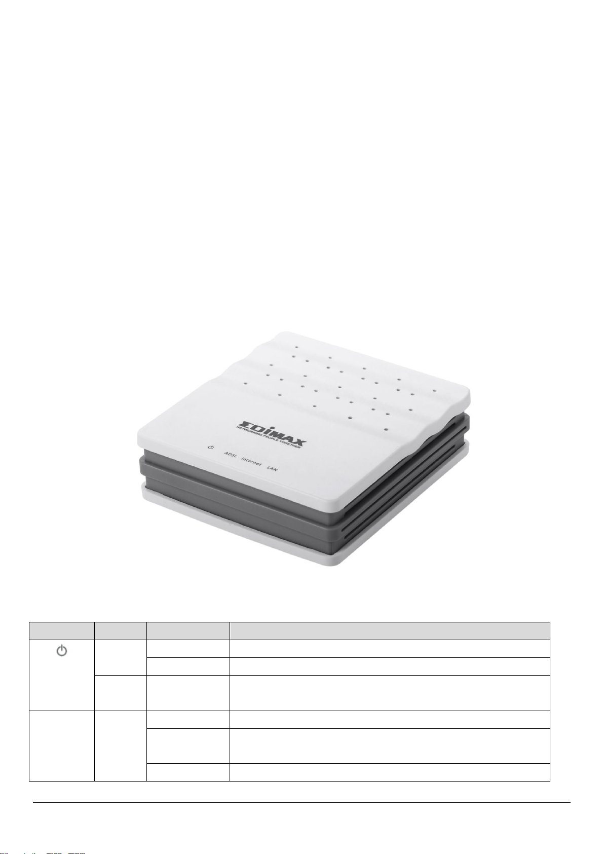
1.4. LED & Button Definitions
Front Panel
Figure 1
6
Page 7
Internet
Green
ON
Internet connected in router mode
BLINK
Internet activity (transferring/receiving data) in
router mode
OFF
Device in bridged mode
Red
ON
Internet not connected in router mode
(Please refer to Note 2)
LAN
Green
ON
LAN port connected
BLINK
LAN activity (transferring/receiving data)
OFF
LAN port not connected
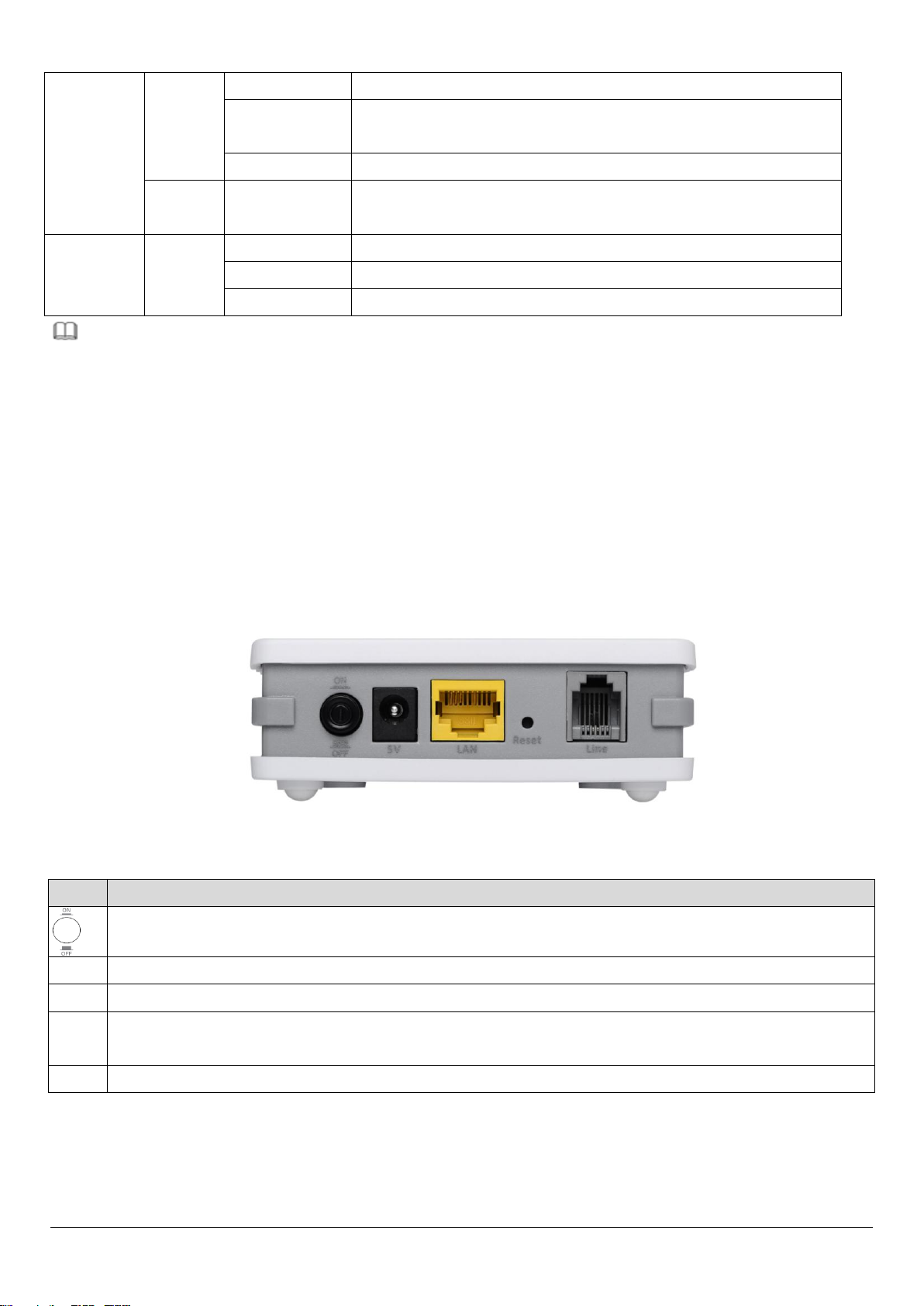
Items
Description
Power ON/OFF
5V
Power connector
LAN
Ethernet RJ-45 port
Reset
Resets device to factory defaults (to reset to factory defaults, push a paper clip into
the hole when the device is powered and hold for more than 10 seconds)
Line
Line RJ-11 port
Note:
1) If the ADSL LED is off, please check your Internet connection. Refer to A .
Hardware Installation for more information about how to connect the router
correctly. If all connections are correct, please contact your ISP to check if there
is a problem with your Internet service.
2) If the Internet LED is red, please check your ADSL LED first. If your ADSL LED
is off, refer to Note 1. If the green ADSL LED is ON, please check your Internet
configuration. You may need to check with your ISP that your Internet is
configured correctly.
Rear Panel
Figure 2
7
Page 8

1.5. Features
The device supports the following features:
Various line modes
External PPPoE dial-up access
Internal PPPoE/PPPoA dial-up access
1483Briged/1483Routed/MER/IPoA access
Multiple PVCs (up to eight) which can be isolated from each other
A single PVC with multiple sessions
Multiple PVCs with multiple sessions
802.1Q and 802.1P protocol
DHCP server
NAPT
Static route
Firmware upgrading through Web, TFTP, or FTP
Reset to factory defaults with reset button or web-based interface.
DNS
Virtual server
DMZ
Two-level passwords and usernames
Web interface
Telnet CLI
System status display
PPP session PAP/CHAP
IP filter
IP quality of service (QoS)
Remote access control
Line connection status test
Remote managing through Telnet or HTTP
Backup and restoration of configuration file
Ethernet interface supporting crossover detection, auto-correction, and
polarity correction
Universal plug and play (UPnP)
8
Page 9

2. Hardware Installation
Step 1. Connect the ADSL line
Connect the Line interface of the device to the Modem interface of a splitter
using a telephone cable. Connect a telephone to the Phone interface of the
splitter using a telephone cable. Connect the Line interface of the splitter to
your existing, incoming line.
The splitter has three interfaces:
Line: Connect to a wall phone jack (RJ-11 jack).
Modem: Connect to the ADSL jack of the device.
Phone: Connect to a telephone set.
Step 2. Connect the router to your LAN network
Connect the LAN interface of the router to your PC, Hub or Switch using an
Ethernet cable (MDI/MDIX).
Note:
Use twisted-pair Ethernet cables to connect the router to a hub or
switch.
Step 3. Connect the power adapter to the router
Plug one end of the power adapter into a wall outlet and connect the other
end to the 5V interface of the device.
The following diagrams show how to correctly connect the router, PC, splitter
and the telephone sets under two different configurations:
Configuration 1
0 shows the correct connection of the router, PC, splitter and the telephone
sets, with no telephone set placed before the splitter.
9
Page 10
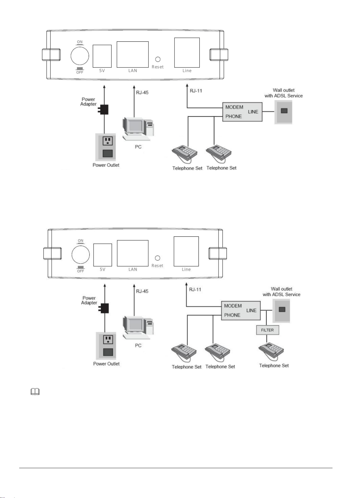
Figure 1 – No telephone before the splitter
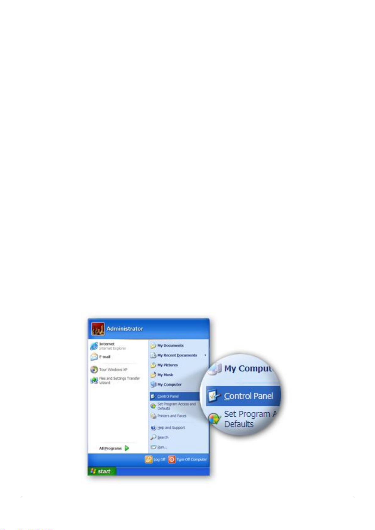
Configuration 2
0 shows the correct connection when a telephone set is installed before the
splitter.
Figure 2 - Telephone set connected before the splitter
Note:
When Configuration 2 is used, the filter must be installed close to the
telephone cable. Do not use the splitter to replace the filter.
Installing a telephone directly before the splitter may lead to failure of
connection between the device and the central office, or failure of Internet
10
Page 11
access, or slow connection speed. If you really need to add a telephone set
before the splitter, you must add a micro filter before a telephone set. Do not
connect several telephones before the splitter or connect several telephones
with the micro filter.
Step 4. Check the ADSL LED status
Please check the ADSL LED on the front panel. This light indicates the status of
your ADSL broadband through your telephone line. If the light is on, you can
continue setup. However if the light is flashing, there is no broadband line
detected. Please call your Internet Service Provider (ISP) and inform them
about the flashing ADSL light to resolve the issue.
Step 5. Firewall settings
Please turn off all personal firewalls before you continue the setup – firewalls
can block communication between your PC and router.
Note: You must use the power adapter included in the package with the
router, do NOT attempt to use a third-party power adapter.
Step 6: PC LAN IP configuration
Configure your PC’s LAN settings to automatically obtain an IP address from
the router by following the steps below:
1. Click “Start” and then select “Control Panel”.
11
Page 12
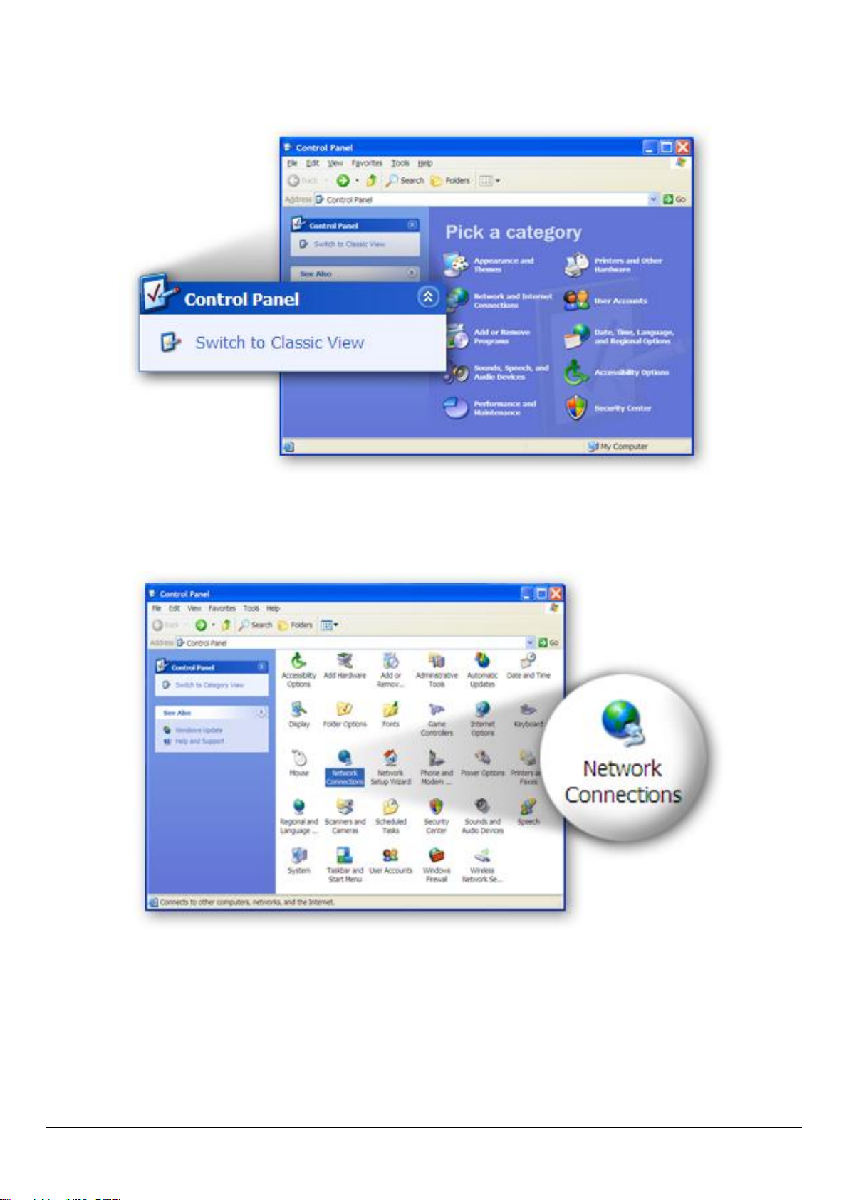
2. Click “Switch to Classic View” in the top left to show additional setting
icons.
3. Locate the “Network Connections” icon and double-click to open network
connection settings.
12
Page 13
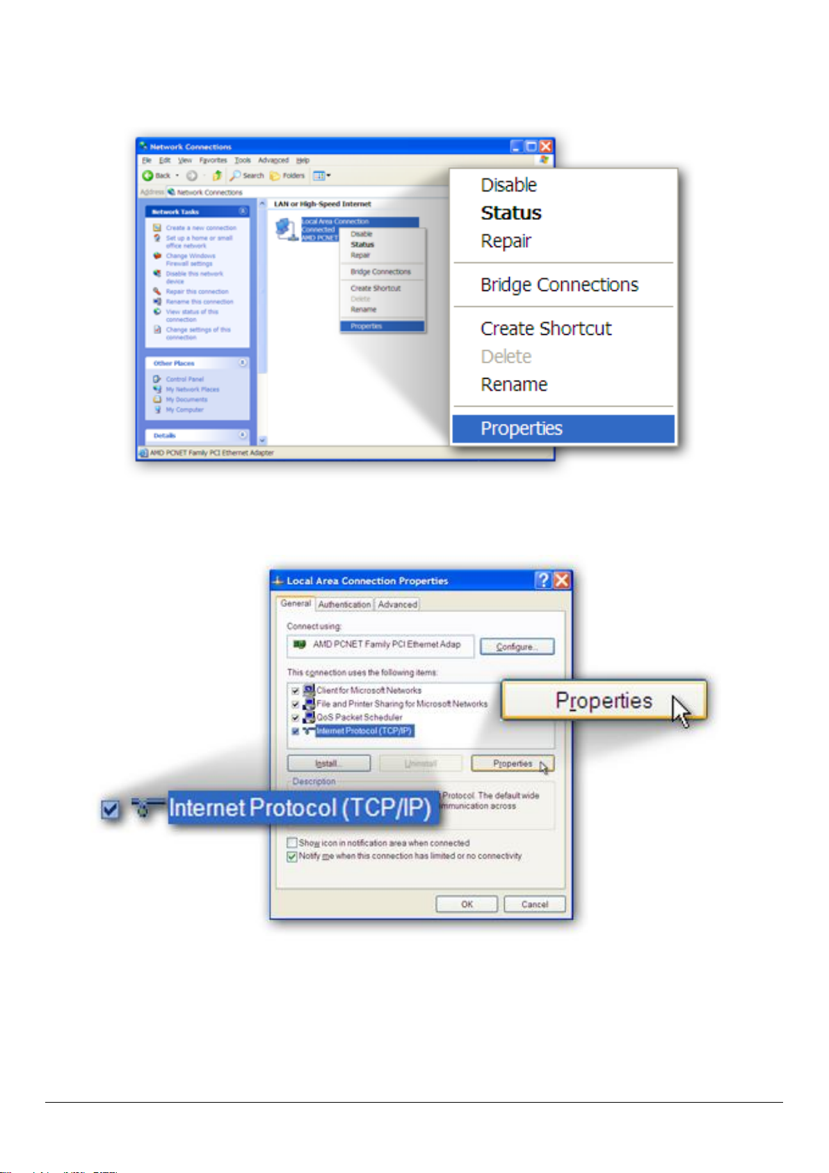
4. Select the “Local Area Connection” icon and right-click it to open the sub-
menu, then select “Properties”.
5. Select “Internet Protocol (TCP/IP)” and then click “Properties”
13
Page 14
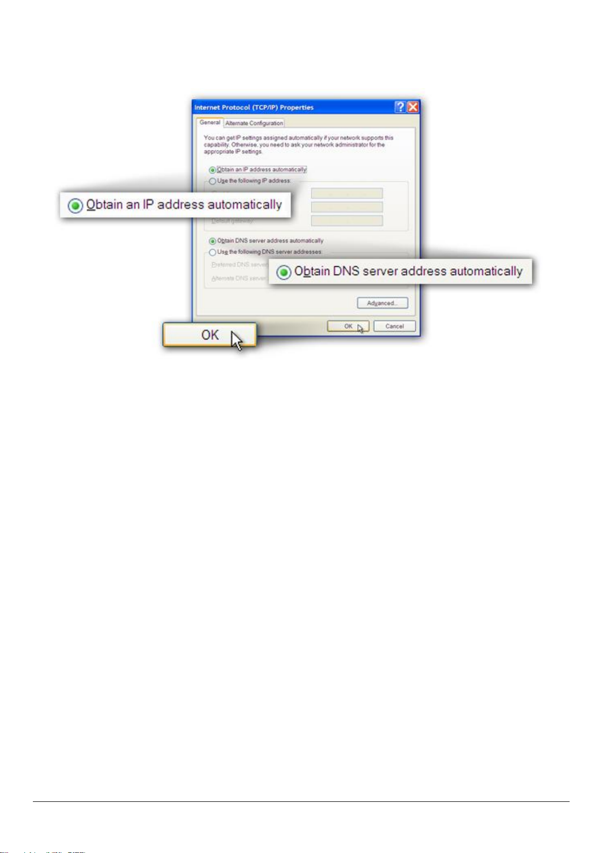
6. Ensure that “Obtain an IP address automatically” and “Obtain DNS
server address automatically” are selected and then press “OK”.
14
Page 15

3. IP Address Setting
To use the router to access the Internet, the PCs in the network must have an
Ethernet adapter installed and be connected to the router either directly or
through a hub or switch. The TCP/IP protocol of each PC has to been installed
and the IP Address of each PC has to be set in the same subnet as the router.
The router’s default IP Address is 192.168.2.1 and the subnet mask is
255.255.255.0. PCs can be configured to obtain IP Address automatically
through the DHCP Server of the router or a fixed IP Address in order to be in
the same subnet as the router. By default, the DHCP Server of the router is
enabled and will dispatch IP Address to PC from 192.168.2.100 to
192.168.2.200. It is strongly recommended to set obtaining IP address
automatically.
This section shows you how to configure your PC’s so that it can obtain an IP
address automatically for either Windows 95/98/Me, 2000 or NT operating
systems. For other operating systems (Macintosh, Sun, etc.), please follow the
manual of the operating system. The following is a step-by-step illustration of
how to configure your PC to obtain an IP address automatically for Windows 7,
Windows Vista and Windows XP.
3.1. Windows 7
1. Click the Start button and select Control Panel. Double click Network and
Internet and click Network and Sharing Center, the Network and Sharing
Center window will appear.
2. Click Change adapter settings and right click on the Local Area Connection
icon and select Properties. The Local Area Connection window will appear.
3. Check your list of Network Components. You should see Internet Protocol
Version 4 (TCP/IPv4) on your list. Select it and click the Properties button.
15
Page 16
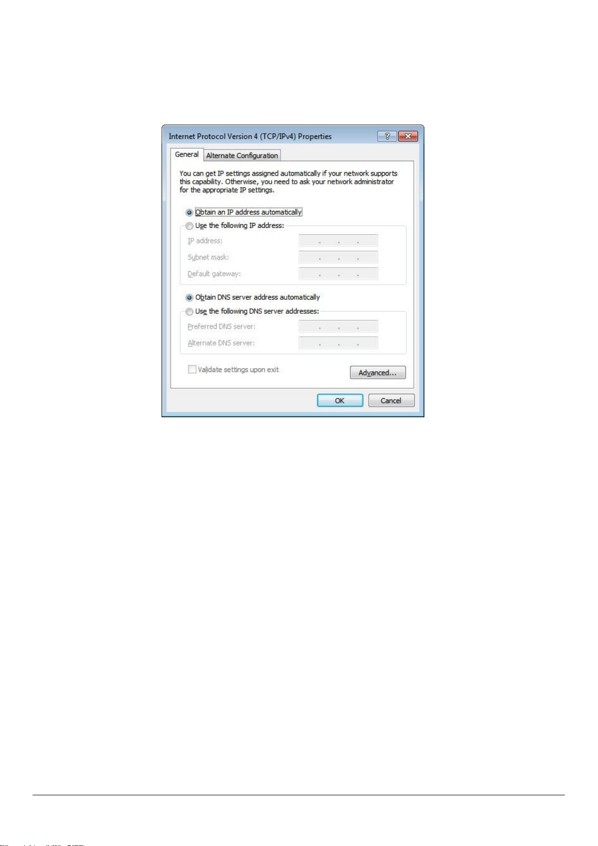
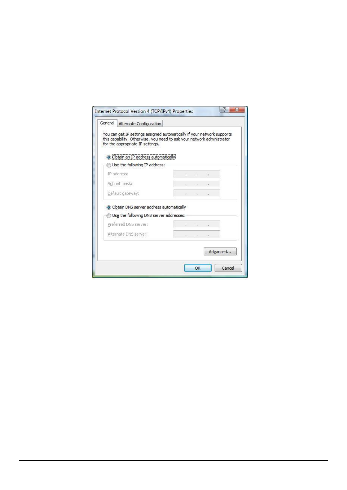
4. In the Internet Protocol Version 4 (TCP/IPv4) Properties window, select
Obtain an IP address automatically and Obtain DNS server address
automatically as shown on the following screen.
5. Click OK to confirm the setting. Your PC will now obtain an IP address
automatically from your router’s DHCP server.
Note: Please make sure that the router’s DHCP server is the only DHCP server
available on your LAN.
3.2. Windows Vista
1. Click the Start button and select Settings and then select Control Panel.
Double click Network and Sharing Center, the Network and Sharing Center
window will appear.
2. Click Manage network connections and right click on the Local Area
Connection icon and select Properties. The Local Area Connection window
will appear.
16
Page 17
3. Check your list of Network Components. You should see Internet Protocol
Version 4 (TCP/IPv4) on your list. Select it and click the Properties button.
4. In the Internet Protocol Version 4 (TCP/IPv4) Properties window, select
Obtain an IP address automatically and Obtain DNS server address
automatically as shown on the following screen.
5. Click OK to confirm the setting. Your PC will now obtain an IP address
automatically from your router’s DHCP server.
Note: Please make sure that the router’s DHCP server is the only DHCP server
available on your LAN.
3.3. Windows XP
1. Click the Start button and select Control Panel and then double click
Network Connections. The Network Connections window will appear.
2. Right click on the Local Area Connection icon and select Properties. The
Local Area Connection window will appear.
17
Page 18
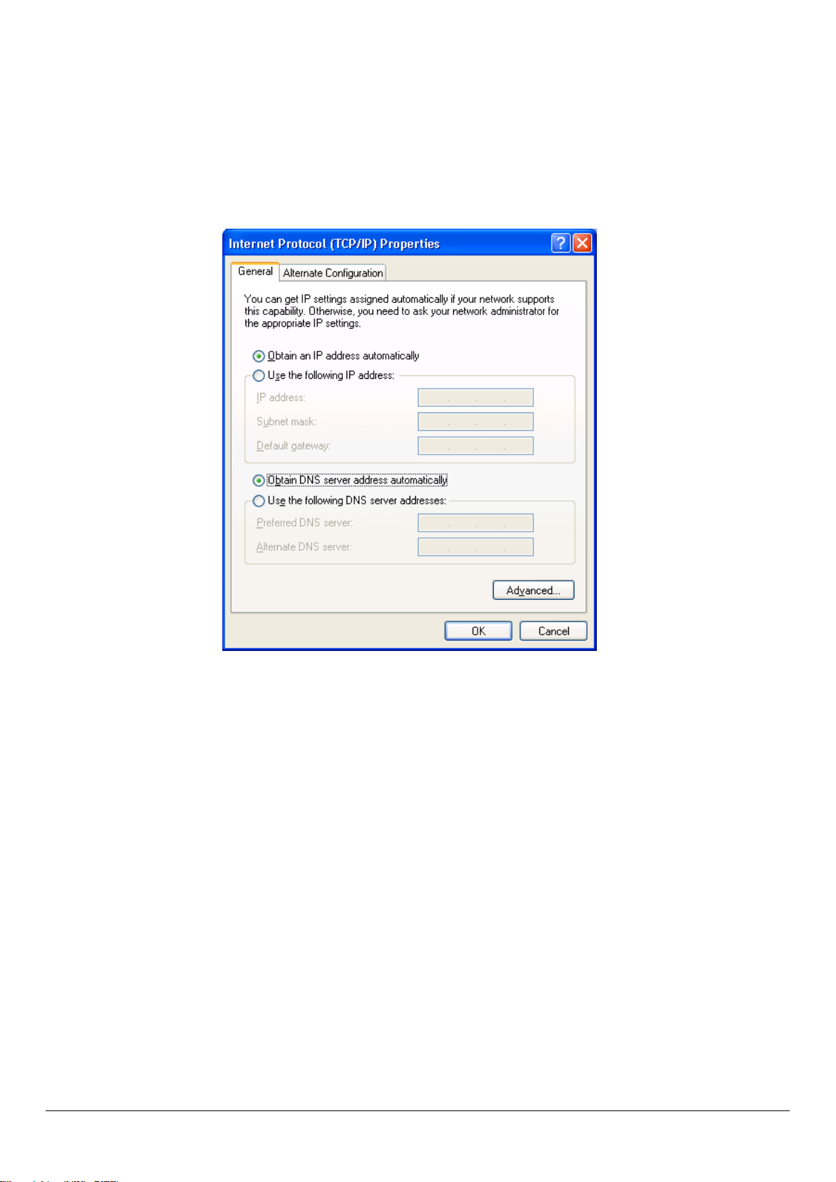
3. Check your list of Network Components. You should see Internet Protocol
[TCP/IP] on your list. Select it and click the Properties button.
4. In the Internet Protocol (TCP/IP) Properties window, select Obtain an IP
address automatically and Obtain DNS server address automatically as
shown on the following screen.
5. Click OK to confirm the setting. Your PC will now obtain an IP address
automatically from your router’s DHCP server.
Note: Please make sure that the router’s DHCP server is the only DHCP server
available on your LAN.
18
Page 19
4. EZmax Setup Wizard
You can configure the router by running the setup wizard on the CD-ROM
included in the package contents. The wizard enables you to configure your
Internet connection, upgrade the firmware and change the router’s
password. Please follow the instructions below.
Alternatively, if you lose the CD-ROM or prefer a web based setup, you can
login to the ADSL router using Internet Explorer, and configure the router
from there using the web-based interface. Instructions for how to do so can
be found in 5. Web Configuration
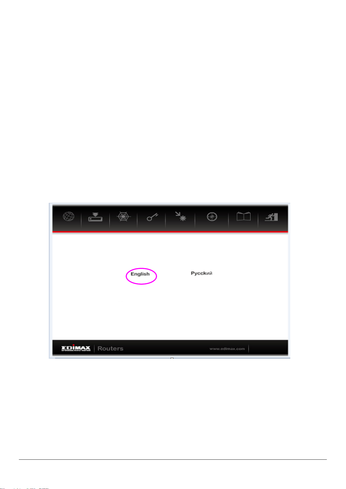
4.1. Setup Wizard
1. When you start the setup wizard, you will see the following screen. Please
choose a language and follow the on screen instructions
19
Page 20
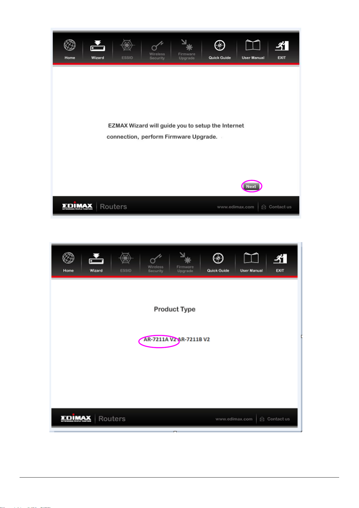
2. Please select your product.
20
Page 21
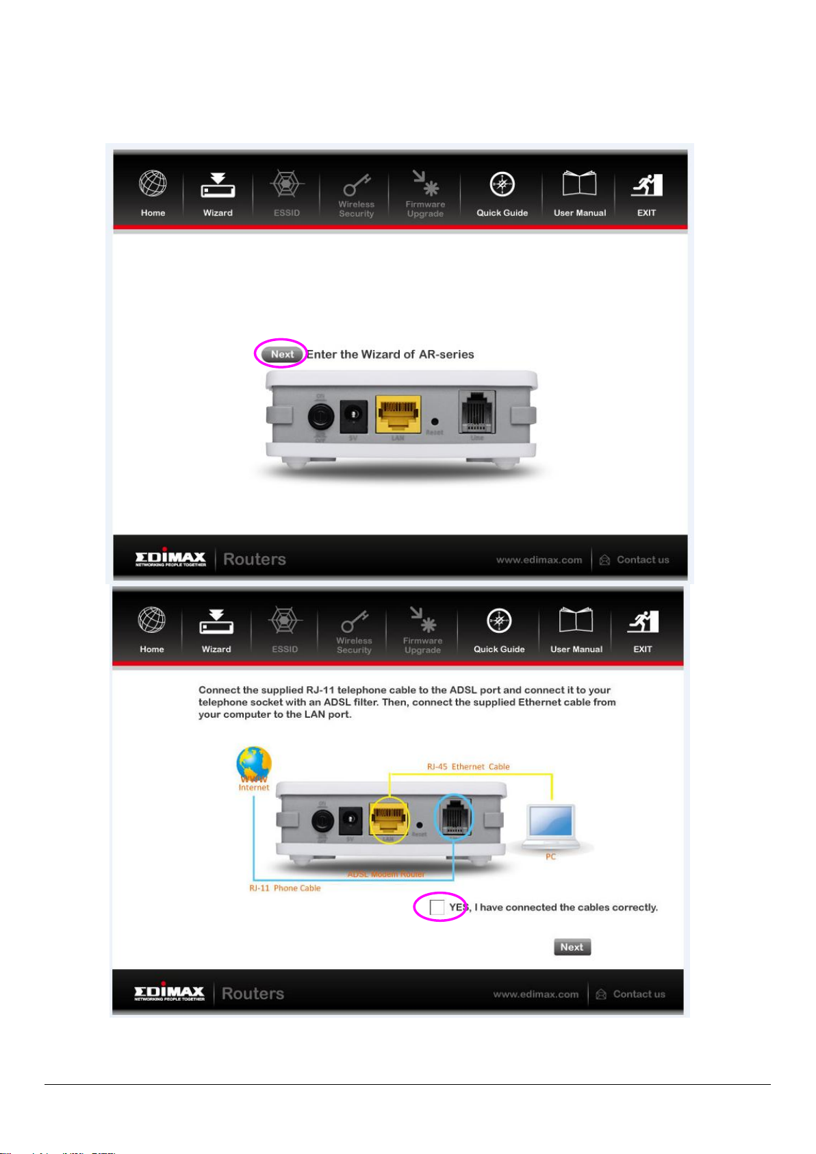
3. Please ensure all hardware is correctly installed. Check the box and click
“Next”
21
Page 22
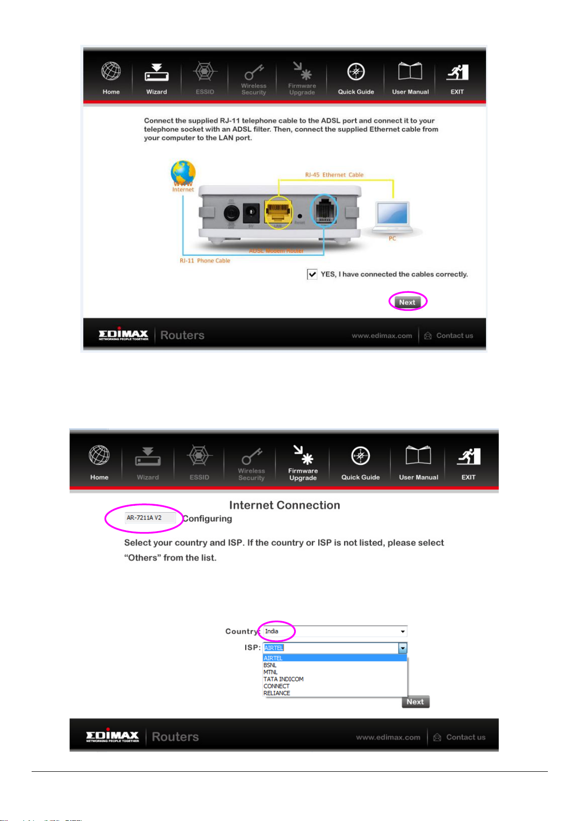
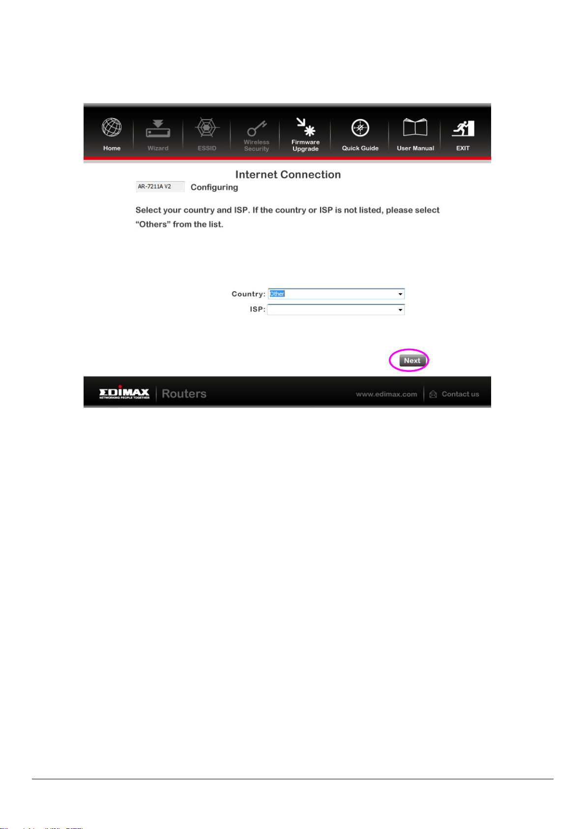
4. Select your country and ISP. If your ISP is not listed, select “Other” from the
list and refer to 4.2. Internet Connection Type.
22
Page 23
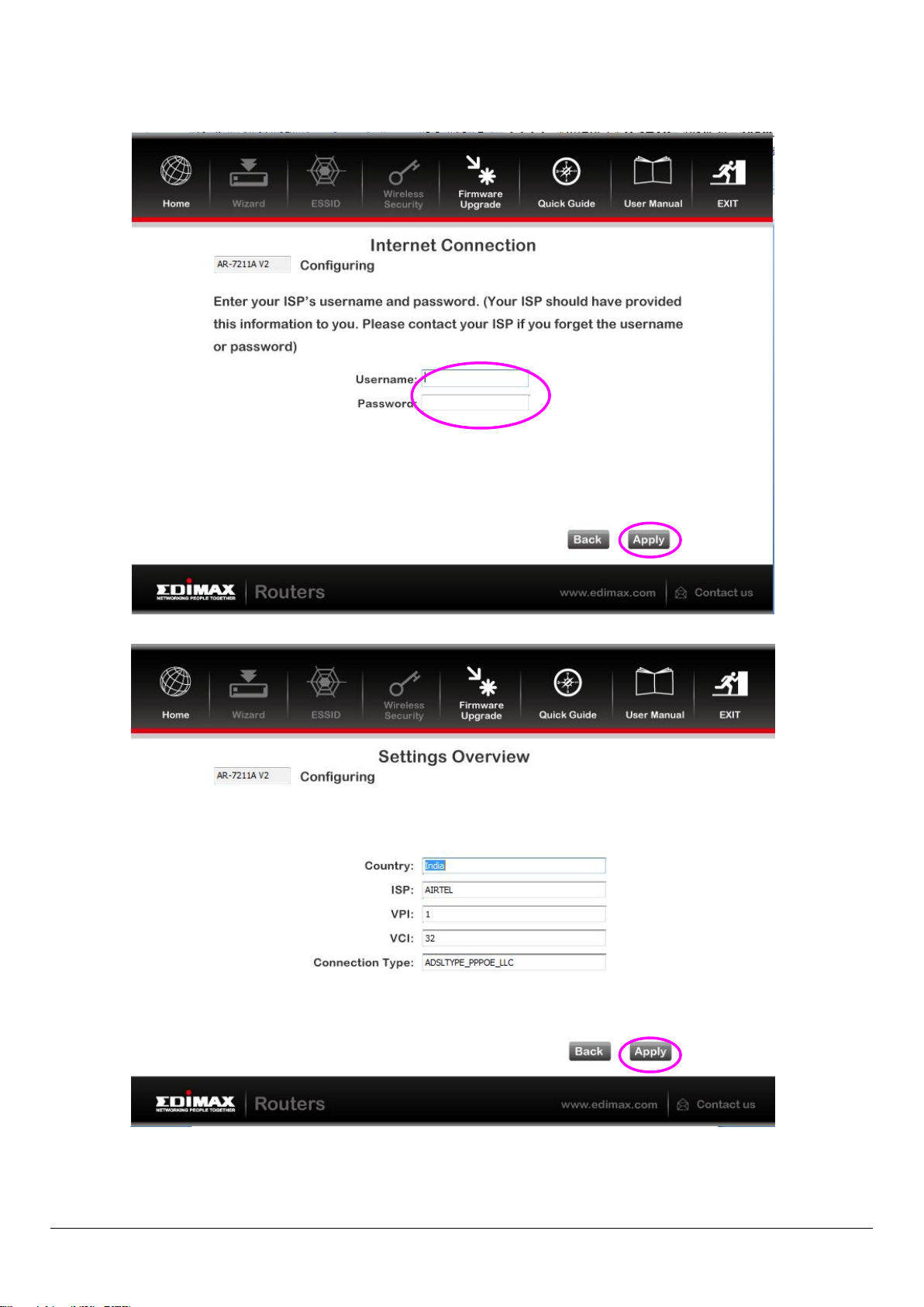
5. Enter your ISP’s username and password and click “Apply”. On the next
screen, click “Apply” again.
23
Page 24
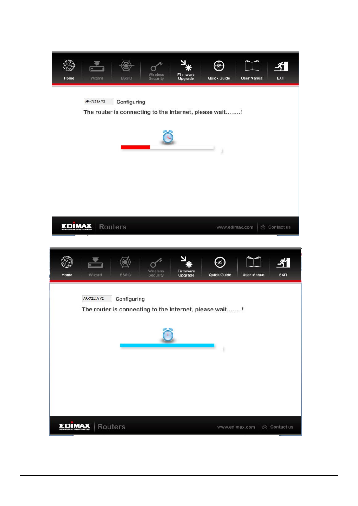
6. Please wait while the router connects to the Internet. When the router is
connected successfully, you will see the screen below.
24
Page 25
4.2. Internet Connection Type
If your country or ISP is not listed, please select “Other” from the list.
Then select your Internet connection type and click “Next”. If you are not
sure, please contact your Internet Service Provider (ISP). Depending on your
selection, please refer to the appropriate chapter 4.1.1.1. PPPoE/PPPoA,
4.1.1.2. Bridge Mode, 4.1.1.3. Dynamic IP Address or 4.1.1.4. Static IP.
25
Page 26
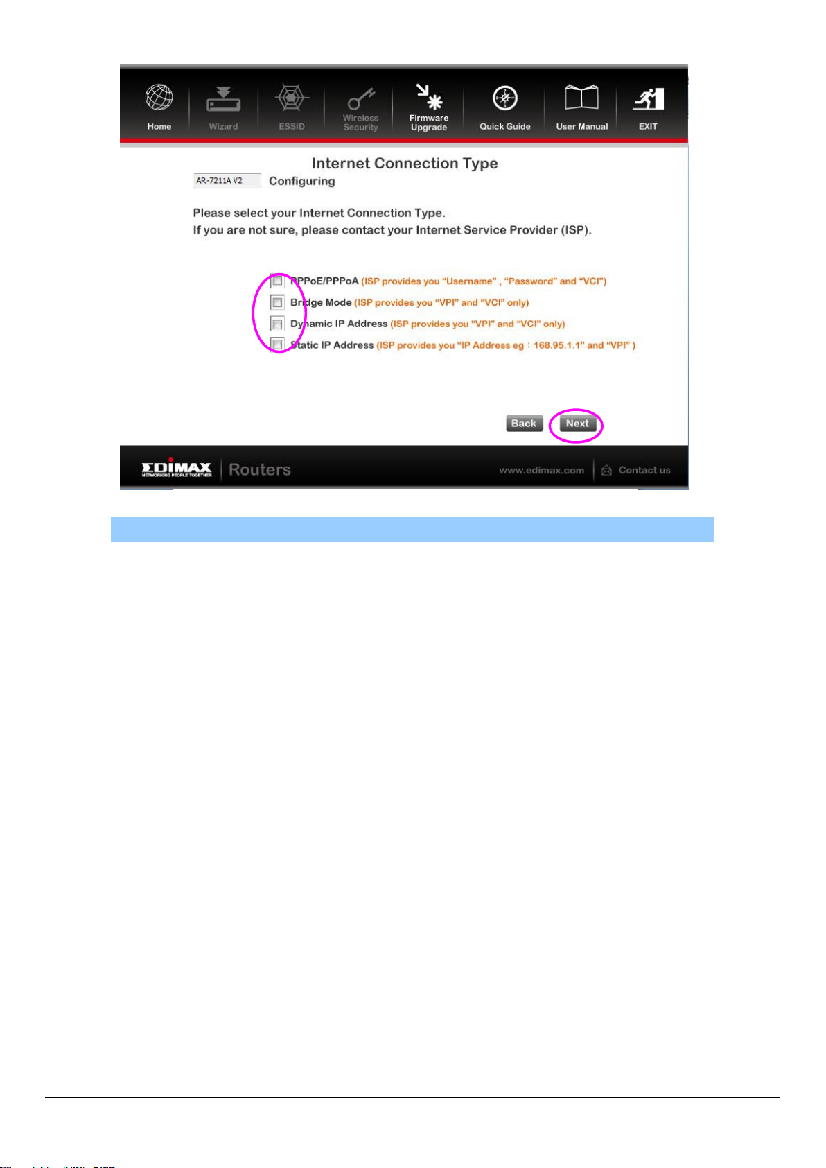
Parameter
Description
PPPoE/PPPoA
PPPoE (PPP over Ethernet) and PPPoA (PPP over
ATM) are common connection methods used for
xDSL.
Bridge Mode
Bridge Mode is a common connection method used
for xDSL modems.
Dynamic IP Address
Obtain an IP address automatically from your service
provider.
Static IP Address
Uses a static IP address. Your service provider gives a
static IP address to access Internet services.
4.2.1.1. PPPoE/PPPoA
26
Page 27
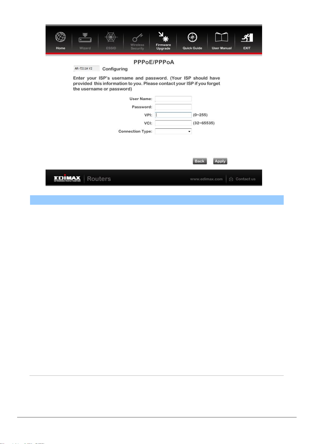
Parameter
Description
User Name
Enter the username exactly as your ISP assigned.
Password
Enter the password that your ISP has assigned to you.
VPI
Virtual path identifier (VPI) is the virtual path between two
points in an ATM network. Its valid value is in the range of 0
to 255. Enter the correct VPI provided by your ISP. By default,
VPI is set to 8.
VCI
Virtual channel identifier (VCI) is the virtual channel between
two points in an ATM network. Its valid value is in the range
of 32 to 65535 (0 to 31 is reserved for local management of
ATM traffic). Enter the correct VCI provided by your ISP. By
default, VCI is set to 35.
Connection type
Please check with your ISP the method of multiplexing. In
PPPoE/PPPoA mode, please select “PPPoE LLC”, “PPPoE
VCMUX”, “PPPoA LLC” or “PPPoA VCMUX”.
27
Page 28

Parameter
Description
VPI
Virtual path identifier (VPI) is the virtual path between two
points in an ATM network. Its valid value is in the range of 0
to 255. Enter the correct VPI provided by your ISP. By default,
VPI is set to 8.
VCI
Virtual channel identifier (VCI) is the virtual channel between
two points in an ATM network. Its valid value is in the range
of 32 to 65535 (0 to 31 is reserved for local management of
ATM traffic). Enter the correct VCI provided by your ISP. By
default, VCI is set to 35.
Connection Type
Please check with your ISP the method of multiplexing. In
Bridge Mode, please select “ADSLTYPE_ROUTER_LLC” or
“ADSLTYPE_ROUTER_VCMUX”.
4.2.1.2. Bridge Mode
28
Page 29

Parameter
Description
VPI
Virtual path identifier (VPI) is the virtual path
between two points in an ATM network. Its valid
value is in the range of 0 to 255. Enter the correct VPI
provided by your ISP. By default, VPI is set to 8.
VCI
Virtual channel identifier (VCI) is the virtual channel
between two points in an ATM network. Its valid
value is in the range of 32 to 65535. (0 to 31 is
reserved for local management of ATM traffic) Enter
the correct VCI provided by your ISP. By default, VCI
is set to 35.
Connection Type
Please check with your ISP the method of
multiplexing. In Bridge Mode, please select
“ADSLTYPE_ROUTER_LLC” or
“ADSLTYPE_ROUTER_VCMUX”.
4.1.1.3. Dynamic IP Address
29
Page 30

Parameter
Description
VPI
Virtual path identifier (VPI) is the virtual path
between two points in an ATM network. Its valid
value is in the range of 0 to 255. Enter the correct VPI
provided by your ISP. By default, VPI is set to 8.
VCI
Virtual channel identifier (VCI) is the virtual channel
between two points in an ATM network. Its valid
value is in the range of 32 to 65535. (0 to 31 is
reserved for local management of ATM traffic) Enter
the correct VCI provided by your ISP. By default, VCI
is set to 35.
Static IP Address
Enter the IP Address assigned by your ISP.
IP Subnet Mask
Enter the Subnet Mask assigned by your ISP.
Gateway
Enter the Gateway assigned by your ISP.
Connection Type
Please check with your ISP the method of
4.2.1.3. Static IP
30
Page 31

multiplexing. In Bridge Mode, please select
“ADSLTYPE_ROUTER_LLC” or
“ADSLTYPE_ROUTER_VCMUX”.
4.3. Firmware Upgrade
The wizard includes a tool to upgrade the router’s firmware. Firmware can
be downloaded from the Edimax website, if you wish to upload new
firmware, select “Firmware Upgrade” from the menu across the top of the
screen.
31
Page 32

5. Web Configuration
The router can also be configured using the web-based configuration interface.
Follow the instructions below.
5.1. Accessing the Router
To access the web-based configuration interface:
1. Open the Internet Explorer (IE) browser and enter http://192.168.2.1.
2. In the Login page that is displayed, enter the username and password.
The username and password of the super user are admin and 1234.
The username and password of a common user are user and user.
If you log in as a super user, the following page will appear. You can check,
configure and modify all settings.
32
Page 33

Field
Description
VPI
Virtual path identifier (VPI) is the virtual path between two
points in an ATM network. Its valid value is in the range of 0 to
255. Enter the correct VPI provided by your ISP. By default, VPI is
set to 8.
VCI
Virtual channel identifier (VCI) is the virtual channel between
two points in an ATM network. Its valid value is in the range of
32 to 65535. (0 to 31 is reserved for local management of ATM
traffic) Enter the correct VCI provided by your ISP. By default, VCI
is set to 35.
If you log in as a common user, you can check the status of the router, but not
configure most of the settings.
5.2. Internet Connection
The Wizard page of the web-based interface allows easy configuration of the
Internet connection and other parameters. The following sections describe
the various parameters you can configure – if you wish, you can leave most of
the parameters set to their default values.
1. To begin using the wizard, click “Wizard” in the navigation bar across the
top of the screen.
Click NEXT to proceed to the next page and select your Internet connection.
33
Page 34

Note: When subscribing to a broadband service, you should be aware of the
method by which you are connected to the Internet. Your physical WAN
device can be either PPP, ADSL, or both. The technical information about the
properties of your Internet connection is provided by your Internet service
provider (ISP). For example, your ISP should inform you whether you are
connected to the Internet using a static or dynamic IP address, and the
protocol that you use to communicate on the Internet. If you are unsure
about your type of Internet connection, please contact your ISP.
2. Select your WAN connection type: PPP over ATM (PPPoA), PPP over
Ethernet (PPPoE), 1483 MER, 1483 Routed or 1483 Bridged and refer to
the appropriate section of the manual accordingly:
5.2.1. PPPoE/PPPoA
Note: The settings for PPPoA and PPPoE connection types are the same.
Set the encapsulation mode to LLC/SNAP and click Next to continue:
34
Page 35

Field
Description
Obtain an IP address
automatically
When this is selected, DHCP assigns IP address for
the PPPoE connection.
Use the following IP address
When this is selected, you need to enter an IP
address for the PPPoE connection, which is
provided by your ISP.
Enable NAT
Check this box to enable network address
translation (NAT). If you do not select it and wish
to access the Internet normally, you must add a
route on the uplink equipment. Usually, it is
required to enable NAT.
Field
Description
PPP Username
Enter the username for PPPoE dial-up, which is
provided by your ISP.
PPP Password
Enter the password for PPPoE dial-up, which is
provided by your ISP.
PPP Connection Type
You can select Continuous (recommended), Connect
on Demand, or Manual.
Continuous: After dial-up is successful, PPPoE
connection is always on-line, whether the data is
being transmitted or not.
Connect on Demand: After dial-up is successful, if
no data is transmitted for the preset idle time, the
router automatically disconnects the PPPoE
Click Next to continue to the next page:
35
Page 36

Field
Description
connection.
Manual: Dial up and disconnect the connection
mannually.
Field
Description
Obtain an IP address
automatically
When this is selected, DHCP assigns IP address
for the PPPoE connection.
Use the following IP address
When this is selected, you need to enter an IP
5.2.2. 1483 MER/1483 Routed
Note: The settings for 1483 Routed and 1483 MER connection types are
the same.
Set the encapsulation mode to LLC/SNAP and click Next to continue:
36
Page 37

Field
Description
address, subnet mask and default gateway for the
WAN connection, which is provided by your ISP.
Obtain DNS server addresses
automatically
When selected, DHCP automatically assigns DNS
server address.
Use the following DNS server
addresses
When selected, you need to manually enter the
primary DNS server address and secondary DNS
server address.
Enable NAT
Check this box to enable network address
translation (NAT). If you do not select it and wish
to access the Internet normally, you must add a
route on the uplink equipment. Usually, it is
required to enable NAT.
5.2.3. 1483 Bridged
Set the encapsulation mode to LLC/SNAP and click Next to continue:
37
Page 38

Field
Description
LAN Interface Setup
LAN IP
Enter the IP address of the LAN interface. Its
valid value is in the range of 192.168.2.1 to
192.168.255.254. The default IP address is
192.168.2.1.
LAN Netmask
Enter the subnet mask of the LAN interface.
Its valid value is in the range of 255.255.0.0 to
255.255.255.254.
Enable Secondary IP
Check this box to enable the secondary LAN
IP. The two LAN IP addresses must be in the
different networks.
DHCP Server
Enable DHCP Server
Check this box to enable DHCP server.
Start IP
Enter the start IP address that the DHCP sever
assigns.
End IP
Enter the end IP address that the DHCP server
assigns.
Max Lease Time
The lease time determines the period that the
PCs retain the assigned IP addresses before
the IP addresses change.
Click Next to continue to the next page:
38
Page 39

Click BACK to modify the settings.
Click FINISH to save the settings.
Click RESET to cancel the settings.
Note: After saving the settings in the Wizard page, the PVC in the Wizard
page replaces that in the Channel Configuration page. The preset PVCs in
the Channel Configuration page do not take effect any more.
5.3. Status
In the navigation bar across the top of the screen, click Status. The page that
is displayed contains Device Info, LAN, WAN, Statistics and ARP.
5.3.1. Device Info
Choose Status > Device Info. The page that is displayed shows the current
status and some basic settings of the router, such as, uptime, software version,
upstream speed, downstream speed and other information.
39
Page 40

5.3.2. LAN
Choose Status > LAN. The page that is displayed shows some basic LAN
settings of the router. In the LAN Status page, you can view the LAN IP
address, DHCP server status, MAC address and DHCP client table. To configure
the LAN network, refer to chapter 5.4.1LAN.
5.3.3. WAN
Choose Status > WAN. The page that is displayed shows basic WAN settings of
the router. In the WAN Status page, you can view basic status of WAN, default
gateway, DNS server. If you want to configure the WAN network, refer to the
chapter 5.4.2.1. WAN.
40
Page 41

5.3.4. Statistics
Choose Status > Statistics. The Statistics page that is displayed contains
Statistics and ADSL Statistics.
5.3.4.1. Statistics
In this page, you can view the statistics of each network interface.
5.3.4.2. ADSL Statistic
Select ADSL Statistic in the left pane to view the ADSL line statistics,
downstream rate, upstream rate and other information.
41
Page 42

5.3.5. ARP
Choose Status > ARP. In the Arp Table page, you can view the table that
shows a list of learned MAC addresses.
5.4. Network
In the navigation bar, click Network. The Network page that is displayed
contains LAN and WAN.
5.4.1. LAN
Choose Network > LAN. The LAN page that is displayed contains LAN IP,
DHCP and DHCP Static IP.
5.4.1.1. LAN IP
Click LAN IP in the left pane to see the following page. Here, you can change
IP address of the router. The default IP address is 192.168.2.1, which is the
private IP address of the router.
42
Page 43

Field
Description
IP Address
Enter the IP address of LAN interface. It is
recommended to use an address from a block that is
reserved for private use. This address block is
192.168.2.1- 192.168.255.254.
Subnet Mask
Enter the subnet mask of LAN interface. The range of
subnet mask is from 255.255.0.0-255.255.255.254.
Secondary IP
Select this to enable the secondary LAN IP address.
The two LAN IP addresses must be in the different
networks.
LAN Port
You can choose the LAN interface you want to
configure.
Link
Speed/Duplex
Mode
You can select the following modes from the dropdownlist:100Mbps/FullDuplex,100Mbps/Half
Duplex,10Mbps/FullDuplex,10Mbps/Half
43
Page 44

Field
Description
Duplex,Auto Negotiation.
MAC Address
Control
Select this to enable access control based on MAC
address. Only a host whose MAC address is listed in
the Current Allowed MAC Address Table can access
the modem.
Add
Enter a MAC address, and click “Add” to add it to the
Current Allowed MAC Address Table.
5.4.1.2. DHCP
Dynamic Host Configuration Protocol (DHCP) allows an individual PC to obtain
TCP/IP configuration from a centralized DHCP server. You can configure this
router as a DHCP server or disable it. The DHCP server can assign an IP
address, IP default gateway and DNS server to DHCP clients. This router can
also act as a surrogate DHCP server (DHCP proxy) where it relays IP address
assignment from an actual real DHCP server to clients. You can enable or
disable DHCP server or DHCP proxy.
Click DHCP in the left pane to see the following page:
44
Page 45

Field
Description
DHCP Mode
If set to DHCP Server, the router can assign IP
addresses, IP default gateway and DNS Servers to the
host in Windows95, Windows NT and other
operation systems that support the DHCP client.
IP Pool Range
This specifies the first and the last IP address in the IP
address pool. The router assigns an IP address that is
in the IP pool range to the host.
Show Client
Click here to display the Active DHCP Client Table
which shows IP addresses assigned to clients.
Default Gateway
Enter the default gateway of the IP address pool.
Max Lease Time
The lease time determines the period that the host
retains the assigned IP addresses before the IP
addresses change.
Domain Name
Enter the domain name if you know it. If you leave
this blank, the domain name obtained by DHCP from
the ISP is used. You must enter a host name (system
name) on each individual PC. The domain name can
be assigned from the router through the DHCP server.
DNS Servers
You can configure the DNS server IP addresses for
DNS Relay.
Set VendorClass IP Range
Click here to display the Device IP Range Table. You
can configure the IP address range based on the
device type.
Click Show Client in the DHCP Mode page to display the Active DHCP Client
Table which shows IP addresses assigned to clients, as shown below:
45
Page 46

Field
Description
IP Address
The IP address assigned to the DHCP client from the
router is displayed here.
MAC Address
The MAC address of the DHCP client is displayed here.
Each Ethernet device has a unique MAC address. The MAC
address is assigned at the factory and consists of six pairs
of hexadecimal character, for example, 00-A0-C5-00-02-
12.
Expiry(s)
The lease time is displayed here. The lease time
determines the period that the host retains the assigned
IP addresses before the IP addresses change.
Refresh
Click to refresh this page.
Close
Click to close this page.
Click Set VendorClass IP Range in the DHCP Mode page, to display the Device
IP Range Table. You can configure the IP address range based on the device
type, as shown below:
46
Page 47

Field
Description
DHCP Mode
If set to DHCP Relay, the router acts a surrogate DHCP
Server and relays the DHCP requests and responses
between the remote server and the client.
Relay Server
Enter the DHCP server address provided by your ISP.
Apply Changes
Click it to save the settings of this page.
Reset
Click it to refresh this page.
In the DHCP Mode field, if you select None you will see the following page:
In the DHCP Mode field, if you select DHCP Relay you will see the following
page:
47
Page 48

Field
Description
IP Address
Enter the specified IP address in the IP pool range,
which is assigned to the host.
Mac Address
Enter the MAC address of a host on the LAN.
Add
After entering the IP address and MAC address, click
“Add” to add a row to the DHCP Static IP Table.
Delete Selected
Select a row in the DHCP Static IP Table, then click
“Delete Selected” to delete this row.
Reset
Resets the fields in this page.
DHCP Static IP Table
Shows the assigned IP address based on the MAC
address.
5.4.1.3. DHCP Static IP
If you select DHCP Static IP in the left pane, you will see the following page.
Here you can assign the IP addresses on the LAN to the specific individual PCs
based on their MAC address.
5.4.2. WAN
Choose Network > WAN. The WAN page that is displayed contains WAN, Auto
PVC, ATM Settings and ADSL Settings.
5.4.2.1. WAN
Click WAN in the left pane, the page shown in the following figure appears.
Here you can configure the WAN interface of your router.
48
Page 49

Field
Description
Default Route Selection
You can select Auto or Specified.
VPI
The virtual path between two points in
an ATM network, ranging from 0 to
255.
VCI
The virtual channel between two
points in an ATM network, ranging
from 32 to 65535 (1 to 31 are reserved
for known protocols).
Encapsulation
You can choose LLC and VC-Mux.
Channel Mode
You can choose 1483 Bridged, 1483
MER, PPPoE, PPPoA, 1483 Routed or
IPoA.
Enable NAPT
Check this box to enable Network
49
Page 50

Field
Description
Address Port Translation (NAPT)
function. If you do not select it and you
want to access the Internet normally,
you must add a route on the uplink
equipment. Usually, it is enabled.
Enable IGMP
Enable or disable Internet Group
Management Protocol (IGMP)
function.
PPP Settings
User Name
Enter the correct user name for PPP
dial-up, which is provided by your ISP.
Password
Enter the correct password for PPP
dial-up, which is provided by your ISP.
Type
You can choose Continuous, Connect
on Demand or Manual.
Idle Time (min)
If set the type to Connect on Demand,
you need to enter the idle timeout
time. If the router does not detect the
flow of the user continuously, within
the preset Idle time, the router
automatically disconnects the PPPoE
connection.
WAN IP Settings
Type
You can choose Fixed IP or DHCP.
If you select Fixed IP, enter the local
IP address, remote IP address and
subnet mask.
If you select DHCP, the router is a
DHCP client and the WAN IP address is
assigned by the remote DHCP server.
Local IP Address
Enter the IP address of WAN interface
provided by your ISP.
50
Page 51

Field
Description
Remote IP Address
Enter the gateway IP address provided
by your ISP.
Netmask
Enter the subnet mask of the local IP
address.
Unnumbered
Check this box to enable IP
unnumbered function.
Add
After configuring the parameters of
this page, select “Add” to add a new
PVC into the Current ATM VC Table.
Modify
Select a PVC in the Current ATM VC
Table, then modify the parameters of
this PVC. When finished, click “Modify”
to apply the settings of this PVC.
Current ATM VC Table
This table shows existing PVCs. It
shows the interface name, channel
mode, VPI/VCI, encapsulation mode,
local IP address, remote IP address and
other information. The maximum
number of items that can be added to
this table is eight.
Click this icon to modify the PVCs’
parameters.
After adding a PPPoE ATM VC, and clicking in PPPoE mode, the following
page will appear. In this page, you can configure the parameters of this PPPoE
PVC.
51
Page 52

Field
Description
Protocol
The protocol type used for this WAN
connection is displayed here.
ATM VCC
The ATM virtual circuit connection
assigned for this PPP interface
(VPI/VCI).
Login Name
The user name provided by your ISP.
Password
The password provided by your ISP.
Authentication Method
You can choose AUTO, CHAP, or PAP.
Connection Type
You can choose Continuous, Connect
on Demand, or Manual.
Idle Time (s)
If you choose Connect on Demand,
you need to enter the idle timeout
time. if the router does not detect
the flow of the user continuously,
within the preset idle time, the
router automatically disconnects the
PPPoE connection.
52
Page 53

Field
Description
Bridge
You can select Bridged Ethernet,
Bridged PPPoE or Disable Bridge.
AC-Name
The accessed equipment type.
Service-Name
The service name is displayed here.
802.1q
You can select Disable or Enable. If
enabled, you need to enter the VLAN
ID. The value ranges from 0 to 4095.
Apply Changes
Click to save the settings of this page
temporarily.
Return
Click to return to the Channel
Configuration page.
Undo
Click to refresh this page.
Source Mac address
The MAC address you want to clone.
MACCLONE
Click it to enable the MAC Clone
function with the MAC address that
is configured.
5.4.2.2. Auto PVC
Selecting Auto PVC in the left pane will bring you to the following page. Here,
you can configure auto PVC detection by adding or deleting items to the auto
PVC search table.
53
Page 54

Field
Description
Probe
After connecting the router to an ADSL outlet using
a telephone cable, click “Probe” and the router will
perform auto detection of the PVCs the official end
supports.
VPI
The virtual path identifier of the ATM PVC. Enter a
value between 0 and 255.
VCI
The virtual channel identifier of the ATM PVC.
Enter a value between 32 and 65535.
Field
Description
VPI
The virtual path identifier of the ATM PVC.
VCI
The virtual channel identifier of the ATM PVC.
QoS
The QoS category of the PVC. You can choose UBR,
CBR, nrt-VBR or rt-VBR.
PCR
Peak cell rate (PCR) is the maximum rate at which
cells can be transmitted along a connection in the
5.4.2.3. ATM Settings
Click ATM Settings in the left pane, and you will see the following page. Here,
you can configure the parameters of the ATM, including QoS, PCR, CDVT, SCR,
and MBS.
54
Page 55

Field
Description
ATM network. Its value ranges from 1 to 65535.
CDVT
Cell delay variation tolerance (CDVT) is the amount
of delay permitted between ATM cells (in
microseconds). Its value ranges from 0 to
4294967295.
SCR
Sustain cell rate (SCR) is the maximum rate that
traffic can pass over a PVC without the risk of cell
loss. Its value ranges from 0 to 65535.
MBS
Maximum burst size (MBS) is the maximum
number of cells that can be transmitted at the PCR.
Its value ranges from 0 to 65535.
5.4.2.4. ADSL Settings
Click ADSL Settings in the left pane, and you will see the following page. In
this page, you can select the DSL modulation. Mostly, it is recommended that
you do not alter the default factory default settings. The router supports the
following modulations: G.Lite, G.Dmt, T1.413, ADSL2, ADSL2+, AnnexL, and
AnnexM. The router negotiates the modulation modes with the DSLAM.
55
Page 56

Field
Description
Attain DNS Automatically
When selected, the router accepts the first
received DNS assignment from one of the PPPoA,
PPPoE or MER enabled PVC(s) during the
connection establishment.
Set DNS Manually
If you select this, enter the IP addresses of the
primary and secondary DNS server.
5.5. Service
In the navigation bar across the top of the screen, click Service. The Service
page which is displayed contains DNS, Firewall, UPNP, IGMP Proxy, TR-069
and ACL.
5.5.1. DNS
Domain Name System (DNS) is an Internet service that translates the domain
name into IP address. Because the domain name is alphabetic, it is easier to
remember. The Internet, however, is based on IP addresses. Every time you
use a domain name, DNS translates the name into the corresponding IP
address. For example, the domain name www.example.com might be
translated to 198.105.232.4. The DNS has its own network. If one DNS server
does not know how to translate a particular domain name, it asks another
one, and so on, until the correct IP address is returned.
Choose Service > DNS. The DNS page that is displayed contains DNS and
DDNS.
5.5.1.1. DNS
Click DNS in the left pane, the page shown in the following figure appears.
56
Page 57

Field
Description
Apply Changes
Click to save the settings of this page.
Reset Selected
Click to restart configuring the parameters in this
page.
Field
Description
DDNS provider
Choose the DDNS provider name. You can choose
DynDNS.org or TZO.
Hostname
The DDNS identifier.
Interface
The WAN interface of the router.
Enable
Enable or disable DDNS function.
Username
The name provided by DDNS provider.
Password
The password provided by DDNS provider.
Email
The email provided by DDNS provider.
Key
The key provided by DDNS provider.
5.5.1.2. DDNS
Click DDNS in the left pane, and you will see the following screen. This page is
used to configure the dynamic DNS address from DynDNS.org or TZO. You can
add or remove DNS configurations.
57
Page 58

5.5.2. Firewall
Choose Service > Firewall. The Firewall page that is displayed contains
IP/Port Filter, MAC Filter, URL Filter, Anti-DoS and Software Forbidden.
5.5.2.1. IP/Port Filter
Click IP/Port Filter in the left pane, and you will see the following screen.
Entries in this table are used to restrict certain types of data packets through
the gateway. These filters are helpful in securing or restricting your local
network.
5.5.2.2. MAC Filter
Click MAC Filter in the left pane, and the following screen will appear. Entries
in this table are used to restrict certain types of data packets from your local
network to Internet through the gateway. These filters are helpful in securing
or restricting your local network.
58
Page 59

Field
Description
URL Blocking Capability
You can choose Disable or Enable.
Select Disable to disable URL blocking function
and keyword filtering function.
Select Enable to block access to the URLs and
keywords specified in the URL Blocking Table.
5.5.2.3. URL Filter
Click URL Filter in the left pane, and you will see the following page. URL
Filter is a function to block a domain name (such as tw.yahoo.com) or filtered
keyword. You can add or delete FQDN and filtered keyword.
The following table describes the parameters and buttons of this page:
59
Page 60

Field
Description
Keyword
Enter the keyword to block.
AddKeyword
Click to add a keyword to the URL Blocking Table.
Delete
Select a row in the URL Blocking Table and click to
delete the row.
URL Blocking Table
A list of the URL (s) to which access is blocked.
5.5.2.4. Anti-DoS
A Denial-of-Service attack (DoS attack) is a type of attack on a network that is
designed to disrupt a network by flooding it with useless traffic. Click Anti-DoS
in the left pane and the following page will appear. Here, you can configure
the settings to prevent DoS attacks.
5.5.2.5. Software Forbidden
Select Software Forbidden in the left pane and you will see the following
screen. This page allows you to configure application control - select an
60
Page 61

Field
Description
Current Forbidden
Software List
A list of applications which are currently
forbidden from accessing the network.
Add Forbidden Software
Select an application to be forbidden from
accessing the network.
application from the drop-down list to prohibit the application from accessing
network resources.
The following table describes the parameters and buttons of this page:
5.5.3. UPNP
Choose Service > UPnP, the page shown in the following figure appears. This
page is used to configure UPnP.
61
Page 62

5.5.4. IGMP Proxy
Choose Service > IGMP Proxy, and you will see the following page. An IGMP
proxy enables the system to issue IGMP host messages on behalf of hosts that
the system discovered through standard IGMP interfaces. The system acts as a
proxy for its hosts after you enable it.
5.5.5. TR-069
Choose Service > TR-069, and you will arrive at the following page. Here, you
can configure the TR-069 CPE.
62
Page 63

Field
Description
ACS
URL
The URL of the auto-configuration server to connect
to.
User Name
The user name for logging in to the ACS.
Password
The password for logging in to the ACS.
Periodic Inform Enable
Select Enable to periodically connect to the ACS to
check whether the configuration updates.
Periodic Inform Interval
Specify the amount of time between connections to
ACS.
Connection Request
User Name
The connection username provided by TR-069
service.
63
Page 64

Field
Description
Password
The connection password provided by TR-069
service.
Debug
Show Message
Select Enable to display ACS SOAP messages on the
serial console.
CPE sends GetRPC
When enabled, the router contacts the ACS to obtain
configuration updates.
Skip MReboot
Specify whether to send an MReboot event code in
the inform message.
Delay
Specify whether to start the TR-069 program after a
short delay.
Auto-Execution
Specify whether to automatically start the TR-069
after the router is powered on.
5.5.6. ACL
Choose Service > ACL and you will arrive at the following screen. Here, you
can permit the data packets from LAN or WAN to access the router. You can
configure the IP address for Access Control List (ACL). If ACL is enabled, only
the effective IP address in the ACL can access the router.
Note: If you select Enable in ACL capability, ensure that your host IP
address is in ACL list before it takes effect.
64
Page 65

Field
Description
Direction Select
Select the router interface. You can select LAN or WAN.
In this example, LAN is selected.
LAN ACL Switch
Choose to enable or disable ACL function.
IP Address
Enter the IP address of the specified interface. Only the IP
address that is in the same network segment with the IP
address of the specified interface can access the router.
Services Allowed
You can choose the following services from LAN: web,
telnet, ssh, ftp, tftp, snmp or ping. You can also choose
all of the services.
Add
After setting the parameters, click “Add” to add an entry
to the Current ACL Table.
Reset
Click to refresh this page.
If you select WAN for Direction Select, then you will see the following page:
65
Page 66

Field
Description
Direction Select
Select the router interface. You can select LAN or WAN.
In this example, WAN is selected.
WAN Setting
You can choose Interface or IP Address.
WAN Interface
Choose the interface that permits data packets from
WAN to access the router.
IP Address
Enter the IP address on the WAN. Only the IP address
that is in the same network segment with the IP address
on the WAN can access the router.
Services Allowed
You can choose the following services from WAN: web,
telnet, ssh, ftp, tftp, snmp or ping. You can also choose
all of the services.
Add
After setting the parameters, click “Add” to add an entry
to the Current ACL Table.
Reset
Click to refresh this page.
66
Page 67

Field
Description
Enable
Select Enable to use static IP routes.
Destination
Enter the IP address of the destination device.
Subnet Mask
Enter the subnet mask of the destination device.
Next Hop
Enter the IP address of the next hop in the IP route to
the destination device.
Metric
The metric cost for the destination.
Interface
The interface for the specified route.
Add Route
Click to add the new static route to the Static Route
Table.
Update
Select a row in the Static Route Table and modify the
parameters. Then click “Update” to save the settings
temporarily.
Delete Selected
Select a row in the Static Route Table and click to
5.6. Advanced
In the navigation bar across the top of the screen, click Advanced. The
Advanced page which is displayed contains Routing, NAT, IP QoS, SNMP and
Others.
5.6.1. Routing
Choose Advanced > Routing, and the page which is displayed contains Static
Route and RIP.
5.6.1.1. Static Route
Click Static Route in the left pane, and you will see the following screen. This
page is used to configure routing information. You can add or delete IP routes.
67
Page 68

Field
Description
delete the row.
Show Routes
Clicking “Show Routes” will display the IP Route Table.
You can view a list of destination routes commonly
accessed by your network.
Static Route Table
A list of the previously configured static IP routes.
Clicking Show Routes will display the following page - the table shows a list of
destination routes commonly accessed by your network.
5.6.1.2. RIP
Click RIP in the left pane and the page shown in the following figure will
appear. If you are using this device as an RIP-enabled router to communicate
with others using Routing Information Protocol (RIP) - enable RIP. This page is
used to select the interfaces on your devices which use RIP, and the version of
the protocol used.
68
Page 69

Field
Description
RIP
Select On, the router communicates with other RIPenabled devices.
Apply
Click to save the settings of this page.
Interface
Choose the router interface that uses RIP.
Receive Version
Choose the interface version that receives RIP messages.
You can choose RIP1, RIP2 or Both.
Choosing RIP1 indicates that the router receives
RIP v1 messages.
Choosing RIP2 indicates that the router receives
RIP v2 messages.
Choosing Both indicates that the router receives
RIP v1 and RIP v2 messages.
Send Version
The working mode for sending RIP messages. You can
choose RIP1 or RIP2.
Choosing RIP1 indicates that the router broadcasts
RIP1 messages only.
Choosing RIP2 indicates that the router multicasts
RIP2 messages only.
Add
Click to add the RIP interface to the Rip Config List.
Delete
Select a row in the Rip Config List and click to delete the
row.
5.6.2. NAT
Choose Advanced > NAT. The submenu contains Setup DMZ, Virtual Server,
NAT Forwarding, ALG, NAT Exclude IP, Port Trigger, FTP ALG Port and NAT IP
Mapping.
5.6.2.1. Setup DMZ
A Demilitarized Zone (DMZ) is used to provide Internet services without
sacrificing unauthorized access to its local private network. Typically, the DMZ
host contains devices accessible to Internet traffic, such as web (HTTP) servers,
FTP servers, SMTP (e-mail) servers and DNS servers. Choose Setup DMZ in the
left pane, and you will see the following page.
69
Page 70

Field
Description
Service Type
You can select a common service type, for
example, AUTH, DNS or FTP. You can also define
a service name.
If Usual Service Name is selected, the
corresponding parameter has the default
settings.
If User-defined Service Name is selected, you
need to enter the corresponding parameters.
To configure DMZ:
Step 1 Select Enable DMZ to enable this function.
Step 2 Enter an IP address of the DMZ host.
Step 3 Click Apply Changes to save the settings of this page temporarily.
5.6.2.2. Virtual Server
Click Virtual Server in the left pane to see the following screen:
70
Page 71

Field
Description
Protocol
Choose the transport layer protocol that the
service type uses. You can choose TCP or UDP.
WAN Setting
You can choose Interface or IP Address.
WAN Interface
Choose the WAN interface that will apply to the
virtual server.
WAN Port
Choose the access port on the WAN.
LAN Open Port
Enter the port number of the specified service
type.
LAN IP Address
Enter the IP address of the virtual server. It is in
the same network segment with LAN IP address
of the router.
5.6.2.3. NAT Forwarding
Click NAT Forwarding in the left pane, and the page shown in the following
figure will appear. Under 1483MER or 1483Routed mode, if NAPT (Network
Address Port Translation) is enabled, the Local IP Address is configured as
192.168.1.3 and the Remote IP Address is configured as 202.32.0.2 - the PC
with the LAN IP192.168.1.3 will use 202.32.0.2 when it is connected to the
Internet via the router without NAPT control.
71
Page 72

Field
Description
Local IP Address
Input a local IP address.
Remote IP Address
Input a remote IP address
Enable
Enable the current configured rule.
Apply Changes
Submit the configurations.
Reset
Cancel the modification and reconfigure the
settings.
Current NAT Port
Forwarding Table
Current configuration rule list.
5.6.2.4. ALG
Click ALG in the left pane and the following page will be displayed. The NAT
ALG(Application Layer Gateways)function enables the router to support
various special application protocols with payloads containing IP addresses
and port numbers, and tries to establish connection between these imbedded
IP addresses and port numbers. Failure of the transformation of such
information may results in problems. The NAT ALG function realizes payload
detection and transformation to ensure normal operation of payloads under
NAT environment, requiring no special configuration of users.
72
Page 73

5.6.2.5. NAT Exclude IP
Click NAT Exclude IP in the left pane, the following screen will be displayed.
Here, you can configure some source IP addresses which use the purge route
mode when accessing internet through the specified interface.
5.6.2.6. Port Trigger
Click Port Trigger in the left pane, the page shown in the following figure will
appear:
Click the Usual Application Name drop-down menu to choose the application
you want to set up for port triggering. When you have chosen an application,
the default Trigger settings will populate the table underneath.
73
Page 74

Field
Description
FTP ALG port
Set an FTP ALG port.
Add Dest Ports
Add a port configuration.
Delete Selected
DestPort
Delete a selected port configuration from the list.
If the application you want to set up is not listed, click the User-defined
Application Name radio button and type in a name for the trigger in the
Custom application field. Configure the Start Match Port, End Match Port,
Trigger Protocol, Start Relate Port, End Relate Port, Open Protocol and Nat
type settings for the port trigger you want to configure.
Click the Apply changes button to finish the setting.
5.6.2.7. FTP ALG Port
Click FTP ALG Port in the left pane to display the following screen. The
common port for FTP connection is port 21, and a common ALG monitors the
TCP port 21 to ensure NAT pass-through of FTP. By enabling this function,
when the FTPserver connection port is not a port 21, the FTP ALG module will
be informed to monitor other TCP ports to ensure NAT pass-through of FTP.
5.6.2.8. NAT IP Mapping
NAT is short for Network Address Translation. The Network Address
Translation Settings window allows you to share one WAN IP address for
multiple computers on your LAN.Click NAT IP Mapping in the left pane, the
page shown in the following figure will appear.
74
Page 75

Entries in this table allow you to configure one IP pool for a specified source IP
address from LAN, so one packet whose source IP is in the range of the
specified address will select one IP address from the pool for NAT.
5.6.3. IP QoS
Choose Advanced > IP QoS, and the page shown in the following figure
appears.
1. Enable IP QoS and click Apply to enable IP QoS function.
2. Click add rule to add a new IP QoS rule.
The page shown in the following figure appears. Entries in the QoS Rule List
are used to assign the precedence for each incoming packet based on physical
LAN port, TCP/UDP port number, source IP address, destination IP address and
other information.
75
Page 76

Field
Description
IP QoS
Select to enable or disable IP QoS function. You need
to enable IP QoS if you want to configure the
parameters of this page.
QoS Policy
You can choose stream based, 802.1p based or DSCP
based.
Schedule Mode
You can choose strict prior or WFQ (4:3:2:1).
Source IP
The IP address of the source data packet.
Source Mask
The subnet mask of the source IP address.
Destination IP
The IP address of the destination data packet.
Destination Mask
The subnet mask of the destination IP address.
Source Port
The port of the source data packet.
Destination Port
The port of the destination data packet.
Protocol
The protocol responds to the IP QoS rules. You can
choose TCP, UDP, or ICMP.
Phy Port
The LAN interface responds to the IP QoS rules.
Set priority
The priority of the IP QoS rules. P0 is the highest
76
Page 77

Field
Description
priority and P3 is the lowest.
IP Precedence
You can choose from 0 to 7 define the priority in the
ToS of the IP data packet.
IP ToS
The type of IP ToS for classifying the data package
You can choose Normal Service, Minimize Cost,
Maximize Reliability, Maximize Throughput, or
Minimize Delay.
802.1p
You can choose from 0 to 7.
delete
Select a row in the QoS rule list and click it to delete
the row.
delete all
Select all the rows in the QoS rule list and click it to
delete the rows.
Field
Description
Enable SNMP
Select Enable to enable SNMP function. You need to
enable SNMP in order to configure the parameters of
this page.
Trap IP Address
Enter the trap IP address. The trap information is sent
to the corresponding host.
5.6.4. SNMP
Choose Advanced > SNMP, the page shown in the following figure will appear.
Here, you can configure the SNMP parameters.
77
Page 78

Community name (readonly)
The network administrators must use this password to
read the information of this router.
Community name (read-
write)
The network administrators must use this password to
configure the information of the router.
Field
Description
Aging Time
If the host is idle for 300 seconds (default value), its entry
is deleted from the bridge table.
802.1d Spanning
Tree
You can select Disabled or Enabled.
Select Enabled to provide path redundancy while
preventing undesirable loops in your network.
Show MACs
Click to show a list of the learned MAC addresses for the
bridge.
5.6.5. Others
Select Advanced > Others. The submenu contains Bridge Setting, Client Limit
and Others.
5.6.5.1. Bridge Setting
Click Bridge Setting in the left pane and you will arrive at the following page.
This page is used to configure the bridge parameters. You can change the
settings or view some information on the bridge and its attached ports.
Click Show MACs and the following page will appear. This table shows a list of
learned MAC addresses for this bridge.
78
Page 79

5.6.5.2. Client Limit
Click Client Limit in the left pane, the page shown in the following figure will
appear. This page is used to configure the capability of force how many
devices can access to Internet.
5.6.5.3. Others
Click Others in the left pane, and you will see the following page. You can
enable half bridge so that the PPPoE or PPPoA connection will set to
Continuous.
79
Page 80

Field
Description
Reboot from
You can choose Save the current configuration or
Restore to the factory default configuration.
Save the current configuration: Saves the
current settings, and then reboots the router.
Restore to the factory default configuration:
Resets to factory default settings, and then
reboots the router.
Reboot
Click to reboot the router.
5.7. Admin
In the navigation bar, click Admin. The Admin page that is displayed contains
Commit/Reboot, Update, Log, Password and Time.
5.7.1. Commit/Reboot
Choose Admin > Commit/Reboot. From here you can set the router reset to
the default settings or set the router to commit the current settings to system
memory.
5.7.2. Update
Choose Admin > Update. The Update Firmware page that is displayed
contains Upgrade Firmware and Backup/Restore.
Caution:
Do not turn off the router or press the Reset button while these
procedures are in progress.
80
Page 81

Field
Description
Select File
Click Browse to select the firmware file.
Upload
After selecting the firmware file, click Upload to
starting upgrading the firmware file.
Reset
Click to starting selecting the firmware file.
Field
Description
Save Settings to File
Click here and select the location to save the
configuration file of the router.
Load Settings from File
Click Browse to select the configuration file.
Upload
After selecting the configuration file, click Upload to
start uploading the configuration file of the router.
5.7.2.1. Upgrade Firmware
Click Upgrade Firmware in the left pane, and you will see the following page.
Here, you can upgrade the firmware of the router.
5.7.2.2. Backup/Restore
Click Backup/Restore in the left pane, and you will see the following page.
You can backup the current settings to a file or restore the settings to a
previously saved file.
81
Page 82

Field
Description
User Name
Choose the user name for accessing the
5.7.3. Log
Choose Admin > Log, from here you can enable or disable system log function
and view the system log.
5.7.4. Password
Choose Admin > Password, and you will see the following page. By default,
the super user name and password are admin and 1234 respectively. The
common user name and password are user and user respectively.
82
Page 83

Field
Description
router. You can choose admin or user.
Privilege
Choose the privilege for the account.
Old Password
Enter the old password
New Password
Enter the password to which you want to
change the old password.
Confirm Password
Enter the new password again.
Field
Description
System Time
Set the system time manually.
NTP Configuration
State
Select enable or disable NTP function. You need to
5.7.5. Time
Choose Admin > Time, the page shown in the following figure appears. You
can configure the system time manually or update the system time from a
time server.
83
Page 84

Field
Description
enable NTP if you want to configure the parameters
of NTP.
Server
Set the primary NTP server manually.
Server2
Set the secondary NTP server manually.
Time Zone
Choose the time zone in which area you are from
the drop down list.
Field
Description
Host
Enter the valid IP address or domain name.
PING
Click it to start to Ping.
5.8. Diagnostic
In the navigation bar, click Diagnostic. The Diagnostic page that is displayed
contains Ping, Traceroute, OAM Loopback, ADSL Statistics and Diag-Test.
5.8.1. Ping
Choose Diagnostic > Ping. The page shown in the following figure will appear.
5.8.2. Traceroute
Choose Diagnostic > Traceroute. Using this route diagnosis you can see the
route your PC data takes to another PC on the Internet.
84
Page 85

Field
Description
Host
The address of a destination host to
be diagnosed.
NumberOfTries
Repeat times.
Timeout
Timeout duration.
Datasize
Data packet size.
DSCP
A differentiated services code point
in the TOS identification byte for
service categories in the IP header of
every data packet. A DSCP prioritizes
by coding values using the used 6-bit
bytes and unused 2-bit bytes.
MaxHopCount
Maximum number of routes.
Interface
Select an interface.
Traceroute
Click to start tracing the route.
Show Result
Click to display the result.
5.8.3. OAM Loopback
Choose Diagnostic > OAM Loopback, and you will see the following page.
Connectivity verification is supported by the use of the OAM loopback
capability for both VP and VC connections. This page is used to perform the
VCC loopback function to check the connectivity of the VCC.
85
Page 86

5.8.4. ADSL Statistics
Choose Diagnostic > ADSL Statistics. The page shown in the following figure
will appear. This page is used for ADSL tone diagnostics.
Click Start to start ADSL tone diagnostics.
5.8.5. Diag-Test
Choose Diagnostic > Diag-Test, and you will arrive at the following page. Here,
you can test the DSL connection. You can also view the LAN status connection
and ADSL connection.
Click Run Diagnostic Test to start testing.
86
Page 87

Question
Answer
Why are all the
indicators off?
Check the connection between the power
adapter and the power socket.
Check whether the power switch is turned on.
Why is the LAN
indicator off?
Check the following:
The connection between the device and your
PC, hub or switch.
The running status of the computer, hub, or
switch.
Why is the ADSL
indicator off?
Check the connection between the Line port of
the device and the wall jack.
Why Internet access
fails while the ADSL
indicator is on?
Check whether the VPI, VCI, user name and
password are correctly entered.
Why I fail to access
the web
configuration page of
the DSL router?
Choose Start > Run from the desktop, and ping
192.168.2.1 (IP address of the DSL router). If the
DSL router is not reachable, check the type of
network cable, the connection between the DSL
router and the PC, and the TCP/IP configuration of
the PC.
How to load the
default settings after
incorrect
configuration?
To restore the factory default settings, turn on the
device, and press the reset button for about 3
seconds, and then release it. The default IP address
and the subnet mask of the DSL router are
192.168.2.1 and 255.255.255.0, respectively.
User/password of super user: admin/1234
User/password of common user: user/user
5.9. Trouble Shooting
87
Page 88

Declaration of Conformity
We, Edimax Technology Co., LTD., declare under our sole responsibility, that the equipment
described below complies with the requirements of the European Council directive
(2004/108/EC, 92/31/EEC, 2006/95/EC).
Equipment
:
Fast Ethernet ADSL2/2+ Modem Router
Model No.
:
AR-7211A V2 / AR-7211B V2
The following European standards for essential requirements have been followed:
EMI:EN 55022:2010
EN 61000-3-2:2006+A1:2009+A2:2009
EN 61000-3-3:2008
EMS:EN 55024:2010
EN 61000-4-2:2009
EN 61000-4-3:2006+A1:2008+A2:2010
EN 61000-4-4:2004+A1:2010
EN 61000-4-5:2006
EN 61000-4-6:2009
EN 61000-4-11:2004
LVD: EN-60950-1:2006
Edimax Technology Co., Ltd.
No. 3, Wu Chuan 3rd Road,
Wu-Ku Industrial Park.
New Taipei City, Taiwan
88
Page 89

89
 Loading...