

Page 1
Page 2

Linux Open Source Code
Certain Edimax products include software codes developed by third parties, which are
subject to the GNU General Public License (GPL) or GNU Lesser General Public License
(LGPL). Please see the GNU (www.gnu.org) website for the terms and conditions of each
license.
The GNU GPL and GNU LGPL software codes used in Edimax products are distributed
without any warranty and are subject to the copyrights of their respective authors. The
firmware files for this product can be found under the “Download” page at the Edimax
website (www.edimax.com).
COPYRIGHT
Copyright Edimax Technology Co., Ltd. all rights reserved. No part of this publication
may be reproduced, transmitted, transcribed, stored in a retrieval system, or translated
into any language or computer language, in any form or by any means, electronic,
mechanical, magnetic, optical, chemical, manual or otherwise, without the prior written
permission from Edimax Technology Co., Ltd.
Edimax Technology Co., Ltd. makes no representations or warranties, either expressed
or implied, with respect to the contents hereof and specifically disclaims any warranties,
merchantability, or fitness for any particular purpose. Any software described in this
manual is sold or licensed as is. Should the programs prove defective following their
purchase, the buyer (and not this company, its distributor, or its dealer) assumes the entire
cost of all necessary servicing, repair, and any incidental or consequential damages
resulting from any defect in the software. Edimax Technology Co., Ltd. reserves the right to
revise this publication and to make changes from time to time in the contents hereof
without the obligation to notify any person of such revision or changes.
The product you have purchased and the setup screen may appear slightly different
from those shown in this QIG. For more information about this product, please refer to the
user manual on the CD-ROM. The software and specifications are subject to change without
notice. Please visit our website www.edimax.com for updates. All brand and product names
mentioned in this manual are trademarks and/or registered trademarks of their respective
holders.
1
Page 3

CONTENTS
CHAPTER I: INTRODUCTION ............................................................................................................................... 4
1-1 Package Contents ................................................................................................................................ 6
1-2 Safety Information ............................................................................................................................... 6
1-3 LED and Interface Description ............................................................................................................. 7
1-4 System Requirements .......................................................................................................................... 8
CHAPTER II: HARDWARE SETUP ......................................................................................................................... 9
CHAPTER III: WEB CONFIGURATION ................................................................................................................ 10
3-1 Connecting to broadband router via web browser ........................................................................... 10
3-2 Status ................................................................................................................................................. 12
3-2-1 System .................................................................................................................................... 12
3-2-2 LAN.......................................................................................................................................... 13
3-2-3 WAN ........................................................................................................................................ 14
3-2-4 Statistics .................................................................................................................................. 15
3-2-4-1 Traffic Statistics ........................................................................................................... 15
3-2-4-2 DSL Statistics................................................................................................................ 16
3-2-5 ARP Table ................................................................................................................................ 17
3-3 Wizard ................................................................................................................................................ 18
3-4 Network \ LAN ................................................................................................................................... 20
3-4-1 LAN Settings ............................................................................................................................ 20
3-4-2 DHCP Settings ......................................................................................................................... 21
3-5 Network \ WAN ................................................................................................................................. 26
3-5-1 WAN Interface ........................................................................................................................ 26
3-5-2 ATM Settings........................................................................................................................... 28
3-5-3 ADSL Settings .......................................................................................................................... 29
3-6 Service & Advance ............................................................................................................................. 30
3-6-1 DNS ......................................................................................................................................... 30
3-6-1-1 DNS Server ................................................................................................................... 30
3-6-1-2 DDNS ........................................................................................................................... 31
3-6-2 Firewall ................................................................................................................................... 32
3-6-2-1 IP/Port Filter ................................................................................................................ 32
3-6-2-2 MAC Filter .................................................................................................................... 33
3-6-2-3 URL Blocking ................................................................................................................ 34
3-6-3 Firewall – II.............................................................................................................................. 35
3-6-3-1 Virtual Services ............................................................................................................ 35
3-6-3-2 DMZ Settings ............................................................................................................... 36
3-6-4 Routing ................................................................................................................................... 37
3-6-4-1 RIP ................................................................................................................................ 37
3-6-4-2 Static Route ................................................................................................................. 38
3-6-5 IP QoS ..................................................................................................................................... 39
3-6-6 Service --II ............................................................................................................................... 40
2
Page 4

3-6-6-1 IGMP Proxy .................................................................................................................. 40
3-6-6-2 UPNP ............................................................................................................................ 41
3-6-6-3 Advance \ Bridge ......................................................................................................... 41
3-6-6-4 Port Mapping ............................................................................................................... 42
3-6-6-5 SNMP ................................................................................................................................... 43
3-6-6-6 Service \ TR06 ...................................................................................................................... 44
3-6-6-7 Service \ ACL ........................................................................................................................ 45
3-7 Admin ................................................................................................................................................. 46
3-7-1 Commit/Reboot ...................................................................................................................... 46
3-7-2 Password................................................................................................................................. 47
3-7-3 Backup/Restore ...................................................................................................................... 48
3-7-4 Firmware Upgrade .................................................................................................................. 49
3-7-5 Time Zone ............................................................................................................................... 50
3-8 Diagnostic .................................................................................................................................. 51
3-8-1 Ping ......................................................................................................................................... 51
3-8-2 ATM Loopback ........................................................................................................................ 52
3-8-3 ADSL ........................................................................................................................................ 52
3-8-4 Diagnostic ............................................................................................................................... 53
APPENDIX A: USB SOFTWARE SETUP ............................................................................................................... 54
APPENDIX B: ABBREVIATIONS.......................................................................................................................... 59
3
Page 5

CHAPTER I: INTRODUCTION
Thank you for purchasing this Edimax product. This router is a cost-effective router, an
ADSL2+ modem, and Ethernet network switch. You can surf the Internet and share the
connection through the router without investing in other devices.
This router can support downstream transmission rates of up to 24Mbps and upstream
transmission rates of up to 1Mbps. It supports PPPoA (RFC 2364 - PPP over ATM Adaptation
Layer 5), RFC 1483 encapsulation over ATM (bridged or routed), PPP over Ethernet (RFC
2516), and IPoA (RFC1577) to establish a connection with ISP. The product also supports
VC-based and LLC-based multiplexing.
You can configure the router by running the Setup Wizard in the CD-ROM provided in
the package. The wizard provides quick setup for the Internet connection, firmware
upgrade and changing router’s password. When you start the Setup Wizard, you will get the
following Welcome screen. Please choose the language to start with and follow the easy
steps in the Wizard. No instruction for the Setup Wizard is given here.
4
Page 6

5 6
Page 7

1-1 Package Contents
One single port router
One external splitter
One power adapter
Two pieces of telephone lines(RJ-11,more than 1.8m)
One piece of Ethernet cable(RJ-45, more than 1.8m)
One piece of USB cable
One copy of Quick Installation Guide
One copy of driver and utility software CD (optional)
1-2 Safety Information
Follow these announcements below to protect the device from risks and damage
caused by fire or electric power.
Use volume labels to mark the type of power.
Use the power adapter packed within the device package.
Pay attention to the power load of the outlet or prolonged lines. An overburden
power outlet or damaged lines and plugs may cause electric shock or fire accident.
Check the power cords regularly. If you find any damage, replace it at once.
Proper space left for heat radiation is necessary to avoid any damage caused by
overheating to the device. The long and thin holes on the Access Point are
designed for heat radiation to make sure the device works normally. Don’t cover
these heat radiant holes.
Do not put this device close to a place where a heat source exits or high
temperature occurs. Avoid the device from direct sunshine.
Do not put this device close to a place where is over damp or watery. Do not spill
any fluid on this device.
Do not connect this device to any PC or electronic product, unless our customer
engineer or your broadband provider instructs you to do this, because any wrong
connection may cause any power or fire risk.
Do not place this device on an unstable surface or support.
Page 8

1-3 LED and Interface Description
LED
Color
Status
Description
Power
Green/
Red
OFF
Device not powered
GREEN
Device correctly powered
RED
Device not correctly powered
RED
BLINK
Upgrade firmware
ADSL
Green
OFF
Initial self-test failed
BLINK
Detecting ADSL
ON
Initial self-test complete
Internet
Green
OFF
Internet connection not established
BLINK
Internet activity (transferring data)
ON
Internet connection established
LAN
Green
OFF
LAN port not connected
BLINK
LAN activity (transferring data)
ON
LAN port connected
USB
Green
OFF
Inactive
ON
Active
Front Panel
7
Page 9

Rear Panel
Item
Usage
Line
Line RJ-11 port
Reset
Resets device to factory defaults
(to restore factory defaults, push a paper clip into the hole
when the device is powered and hold for over 5 seconds)
Ethernet
Ethernet RJ-45 port
Power ON/OFF
PWR
Power connector
(connects to DC12V 500mA power adapter)
USB
Connects to computer via USB cable
(USB driver installation required. See APPENDIX A for details.)
1-4 System Requirements
First, make sure that you have prepared these following items to guarantee the router
can work properly.
Service subscription
An 10BaseT/100BaseT Ethernet card installed on your PC
HUB or Switch (attached to several PCs through one of Ethernet interfaces on the
device)
Operating system: Windows 98SE, Windows 2000, Windows ME, or Windows XP
Internet Explorer V5.0 or higher, or Netscape V4.0 or higher, or Firefox 1.5 or
higher
8
Page 10

CHAPTER II: HARDWARE SETUP
1. Connect the “Line” port of the router and the “Modem” port of the splitter with a
telephone (RJ-11) cable.
2. Connect the “Ethernet” port of the router to a computer via an Ethernet cable
(MDI/MDIX).
3. Plug the power adapter to a wall outlet and then connect the other end to the
“Power” port of the router.
9
Page 11
CHAPTER III: WEB CONFIGURATION
3-1 Connecting to broadband router via web browser
You can access the broadband router’s web-based configuration interface via any
connected computer with a web browser (Internet Explorer 5.x or above, Firefox, Opera, or
Safari).
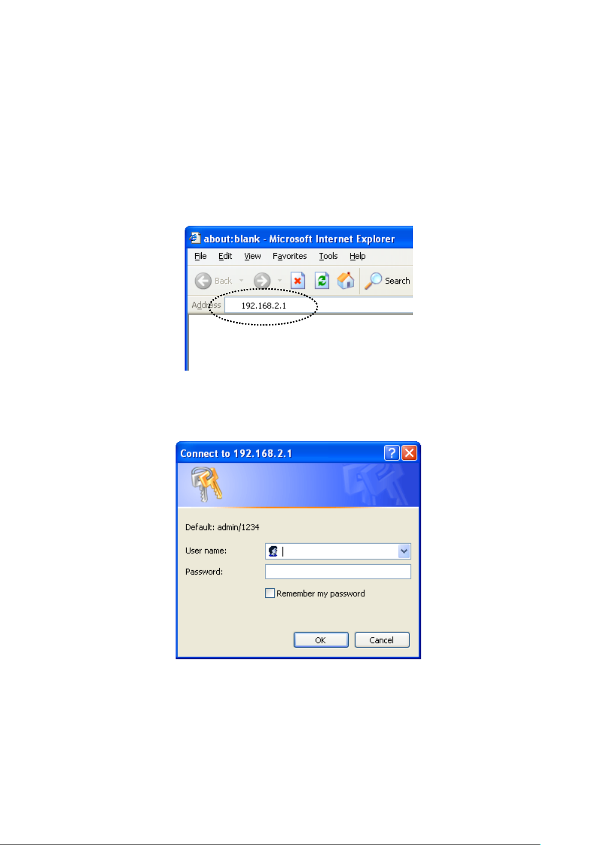
1. Please input “192.168.2.1” in the web browser’s address bar and press “Enter”.
2. You should see the following authentication window.
NOTE: If you cannot access the broadband router’s web-based configuration
interface, the IP address you have inputted may be incorrect. If you have previously
changed the router’s IP address, please input the one you have designated.
10
Page 12
3. Please input “admin” in the “User name” field and “1234” in the “Password” field.
Click the “OK” button to enter the web configuration interface.
11
Page 13
3-2 Status
Click “Status” in the menu to open the sub-menu that contains 5 items: System, LAN,
WAN, Statistic, and ARP Table.
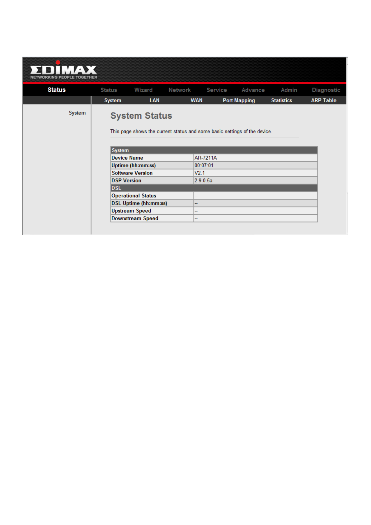
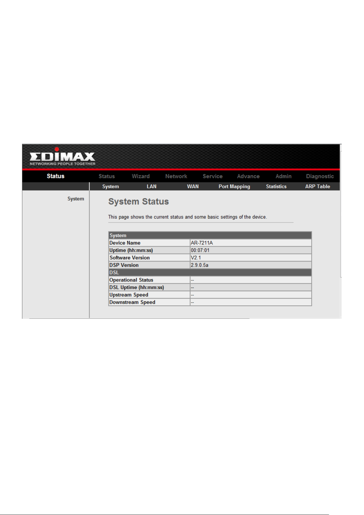
3-2-1 System
Click “System” in the sub-menu to open the following screen. In this page, you can view
the status and some basic settings of this router, for example, Software Version, DSL mode,
Upstream Speed, Downstream Speed, Uptime and so on.
12
Page 14
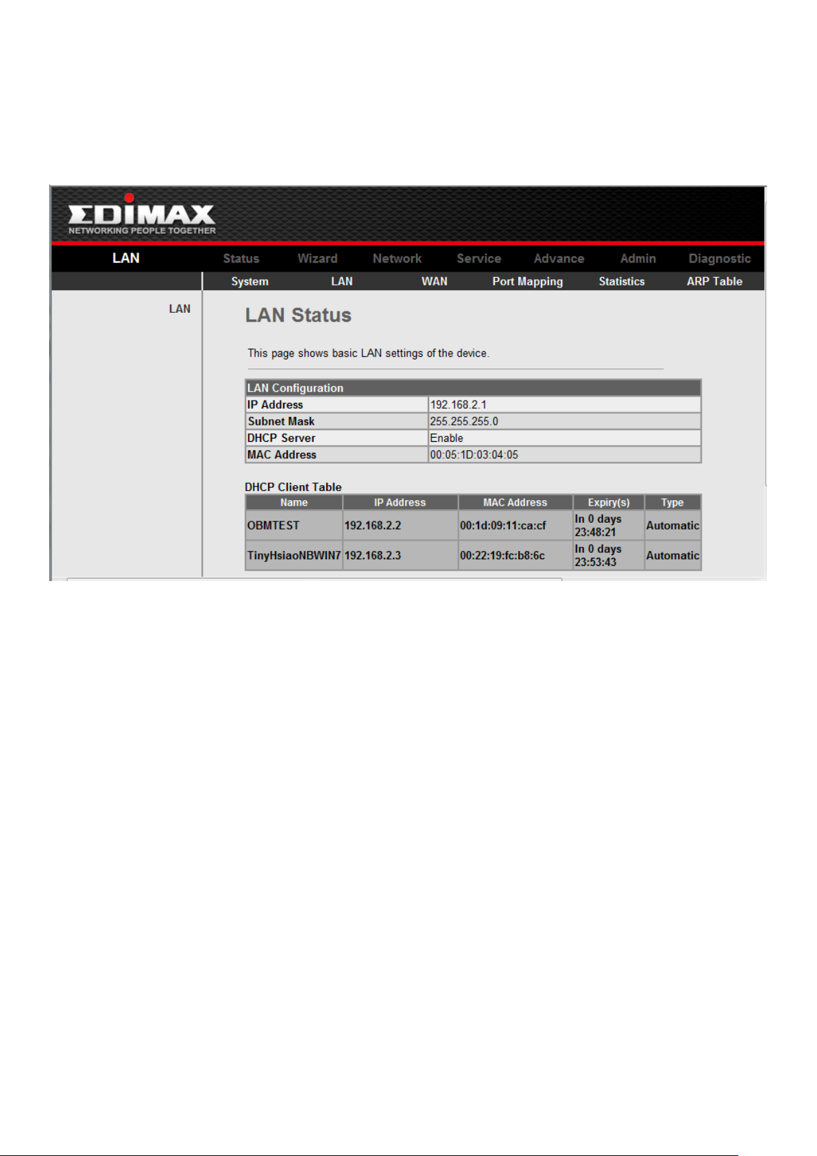
3-2-2 LAN
Click “LAN” in the sub-menu to open the following screen. In this page, you can view
the LAN IP, DHCP Server status, MAC Address and DHCP Client Table.
13
Page 15

3-2-3 WAN
Click “WAN” in the sub-menu to open the following screen. In this page, you can view
basic status of WAN, Default Gateway, and DNS Server.
14
Page 16
3-2-4 Statistics
Click “Statistics” in the sub-menu to open the menu in the left bar that contains two
items: Traffic Statistics and DSL Statistics.
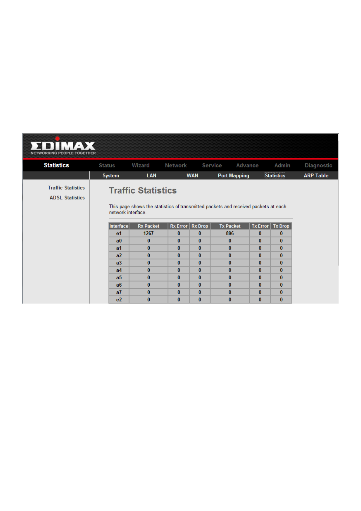
3-2-4-1 Traffic Statistics
Click “Traffic Statistic” in the left bar to open the following screen. In this page, you can
view the statistics of each network port.
15
Page 17
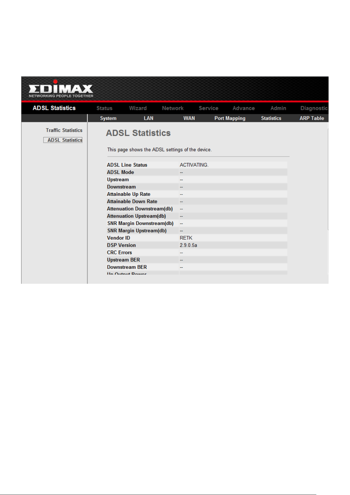
3-2-4-2 DSL Statistics
Click “DSL Statistics” in the left bar to open the following screen. In this page, you can
view the ADSL line statistics, downstream rate, and upstream rate.
16
Page 18
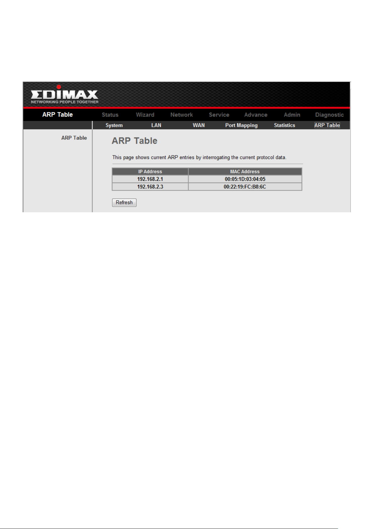
3-2-5 ARP Table
Click “ARP Table” in the sub-menu to open the following screen. In this page, you can
view the table that shows a list of learned MAC addresses.
17
Page 19
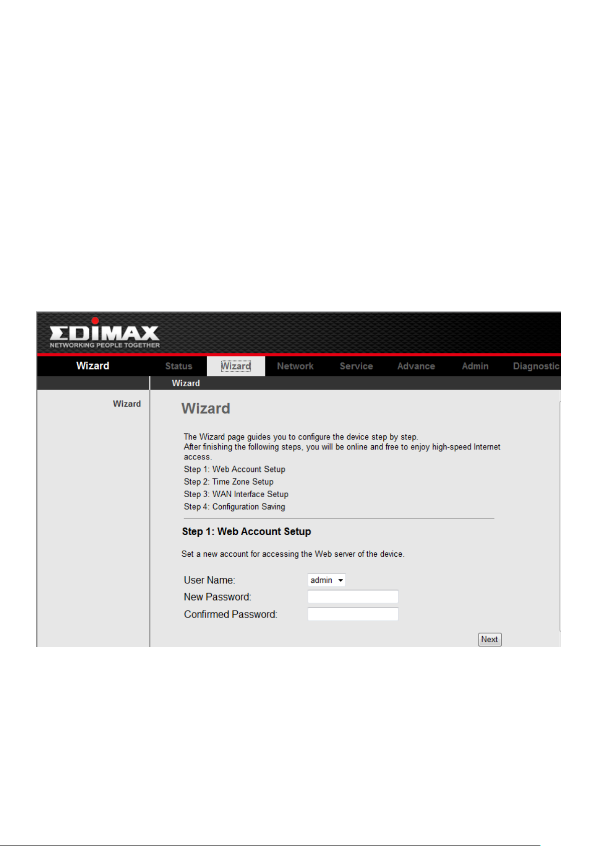
3-3 Wizard
The setup wizard enables speedy and accurate configuration of your Internet
connection and other important parameters. The following sections describe these various
configuration parameters. Whether you configure these parameters or use the default ones,
click “Next” to enable your Internet connection.
When subscribing to a broadband service, you should be aware of the method by which
you are connected to the Internet. Your physical WAN device can be either Ethernet, DSL, or
both. Technical information regarding the properties of your Internet connection should be
provided by your Internet Service Provider (ISP). For example, your ISP should inform you
whether you are connected to the Internet using a static or dynamic IP address, or what
protocols, such as PPPOA or PPPoE, you will be using to communicate over the Internet.
Click Wizard in the sub-menu to open the screen of Fig 3.3.1-1. In this page, and the
Wizard will guide you to finish password/time/Internet connection settings.
Fig 3.3.1-1
Be sure to use the correct Virtual Path Identifier (VPI) and Virtual Channel Identifier
(VCI) numbers assigned to you. The valid range for VPI is 0 to 255 and for VCI is 1 to 65535.
18
Page 20

Then press Next, the Fig 3.3.1-2 screen will appear. In this page, you can select the WAN
Connect Type and the encapsulation method.
Fig 3.3.1-2
If you finish the settings of this page, click Next, the screen appears as shown next.
Fig 3.3.1-3
19
Page 21

3-4 Network \ LAN
Click LAN in the menu to open the sub-menu which contains 2 items: LAN Settings and
DHCP Settings. You can use the LAN configuration to define an IP address for the DSL
Router and configure the DHCP server.
3-4-1 LAN Settings
On this screen you can change the device's IP address. The preset IP address is
192.168.1.1. This is the Private IP address of the DSL Router. This is the address under which
the device can be reached in the local network. It can be freely assigned from the block of
available addresses.
Click LAN Settings in the sub-menu to open the screen of Fig 3.4.1. In this page you can
config the LAN network.
Fig 3.4.1
20
Page 22

The following table describes the fields of this screen.
Label
Description
IP Address
Input the IP of Local area network interface here.
Subnet Mask
We recommend that you use an address from a block
that is reserved for private use. This address block is
192.168.1.1- 192.168.255.254
Secondary IP
Select this checkbox to enable the secondary LAN IP.
The two LAN IP must be in the different network.
Apply Changes
Click this button to save the settings of this page.
3-4-2 DHCP Settings
DHCP(Dynamic Host Configuration Protocol) allows the individual client(computers) to
obain the TCP/IP configuration at start-up from the centralize DHCP server. You can
configure this router as a DHCP server or disable it. DHCP server can assign IP address, an IP
default gateway and DNS server to DHCP clients. This router can also act as a surrogate
DHCP server(DHCP Proxy) where it relays IP address assignment from a actual real DHCP
server to clients.
If the DHCP was disabled, the screen of Fig 3.4.2-1 appears. You can enable/disable
DHCP Server or DHCP Proxy.
Fig 3.4.2-1
21
Page 23

If you set to DHCP Proxy, the screen of Fig 3.4.2-2 appears.
Label
Description
DHCP Proxy
If set to DHCP Proxy, your ROUTER acts a surrogate
DHCP Server and relays the DHCP requests and
reponses between the remote server and the client.
DHCP Server
Address
Enter the IP address of the actual, remote DHCP server
in this field.
Apply Changes
Click this button to save the changes of this page.
Fig 3.4.2-2
The following table describes the fields of this screen.
22
Page 24

If you set to DHCP Server, the screen of Fig3.4.2-3 appears as shown next.
Label
Description
DHCP Server
If set to DHCP Server, your ROUTER can assign IP
addresses, an IP default gateway and DNS Servers to
Windows95, Windows NT and other systems that
support the DHCP client.
IP Pool Range
This field specifies the first and the last of contiguous IP
address of the IP address pool.
Show Client
Click this button, the screen of Fig 3.5.2-4 appears,
which shows the assigned IP address of the clients.
Max Lease Time
The Lease time determines the period for which the
PCs retain the IP addresses assigned to them without
changing them.
Domain Name
Input the domain name here if you know. If you leave
this blank, the domain name obtained by DHCP from
the ISP is used. While you must enter host
name(System Name) on each individual computer, the
domain name can be assigned from this router via
DHCP server.
Gateway Address
Enter the IP default gateway of the IP address pool.
MAC-Base
Assignment
Click this button, the screen of Fig3.5.2-5 appears. This
function allows you assign IP addresses on the LAN to
specific individual computers based on their MAC
address.
Apply Changes
Click this button to save the changes of this page.
Fig 3.4.2-3
The following table describes the fields in this screen.
23
Page 25

Label
Description
IP Address
This field displays the IP address relative to the MAC
address.
MAC Address
This field displays the MAC(Media Access Control)
address of the computer.
Every Ethernet device has a unique MAC address. The
MAC address is assigned at the factory and consists of
six pairs of hexadecimal character, for example,
00-A0-C5-00-02-12.
Time Expired(s)
Here shows the lease time. The Lease time determines
the period for which the PCs retain the IP addresses
assigned to them without changing them.
Refresh
Click this button to refresh the Active DHCP Client
Table.
Close
Click this button to close this window.
Click Show Client, the following window appears. In this window, you can view the IP
address assigned to each DHCP client.
Fig 3.4.2-4
The following table describes the fields in this screen.
24
Page 26

Click MAC-Base Assignment button, the below window appears. In this page, you can
Label
Description
Host MAC Address
Type the MAC address of a computer on your LAN
Assigned IP Address
This field specifics the IP of the IP address pool.
Assign IP
Click this button after entered Host MAC Address and
Assigned IP Address, a row will be added in MAC-Base
Assignment Table.
Modify Assigned IP
Select a row in MAC-Base Assignment Table, the MAC
address and IP address will appears Host MAC
Address and Assigned IP Address. After modified the
MAC Address and IP Address, click this button to save
the changes.
Delete Assigned IP
Select a row in MAC-Base Assignment Table, then click
this button, this row will be deleted.
Close
Click this button to close this window.
MAC-Base
Assignment Table
This table shows the assigned IP address based on the
MAC address.
assign IP addresses on the LAN to specific individual computers based on their MAC
address.
Fig 3.4.2-5
The following table describes the fields of this screen.
25
Page 27

3-5 Network \ WAN
Label
Description
VPI
(Virtual Path Identifier) The virtual path between two
Click WAN Interface in the menu to open the sub-menu which contains 3 items: WAN
Interface, ATM Settings and ADSL Settings.
3-5-1 WAN Interface
Click WAN Interface in the sub-menu to open the screen of Fig 3.5.1-1. In this page, you
can configure WAN Interface of your router.
Fig 3.5.1-1
26
Page 28

points in an ATM network, and its valid value is from 0
to 255
VCI
The virtual channel between two points in an ATM
network, ranging from 32 to 65535 (1 to 31 are
reserved for known protocols)
Encapsulation
Choices are LLC and VC-Mux.
Channel Mode
There are five choices: 1483 Bridged, 1483 MER,
PPPoE, PPPoA and 1483 Routed.
Admin Status
If select Disable, this PVC will be unusable.
Enable NAPT
Select it to enable the NAPT functions of the MODEM.
If you are not to enable NAPT and intend the user of
the MODEM to access the Internet normally, you must
add a route on the uplink equipment; otherwise the
access to the Internet will fail. Normally, it is required
to enable NAPT.
PPP Settings
Login Name
The correct user name that your ISP has provided to
you.
Password
The correct password that your ISP has provided to you
Connection Type
The choices are Continuous, Connect on Demand and
Manual.
Idle Time(min)
If select Connect on Demand, you need to input the
idle timeout time. Within the preset minutes, if the
MODEM doesn’t detect the flow of the user
continuously, the MODEM will automatically
disconnect the PPPOE connection.
WAN IP Settings
Type
The choices are Fixed IP and Use DHCP. If set Fixed IP,
you should enter the Local IP Address, Remote IP
Address and Subnet Mask. If set Use DHCP, your
MODEM will be a DHCP client, the WAN IP will be
assigned by the remote DHCP server.
Local IP Address
This is the IP of WAN interface which is provided by
your ISP.
Remote IP Address
This is the gateway IP which is provided by your ISP.
Subnet Mask
This is the Subnet Mask of the Local IP Address.
Unnumbered
Select this checkbox to enable IP Unnumbered
function.
Default Route
Add
After configuring the parameters of this page, click this
button then a new PVC will be added into Current ATM
27
Page 29

VC Table.
Modify
Select a PVC in the Current ATM VC Table, then modify
the parameters of this PVC. When you finish, click this
button to apply the change of this PVC.
Delete Selected
Select a PVC in the Current ATM VC Table, then click
this button to delete this PVC.
Click this button, the following screens will appear. In
these pages, you can modify the PVCs’ parameters.
3-5-2 ATM Settings
Click ATM Setting, the screen of Fig 3.5.1-3 will appear. In this page, you can configure
the parameters of the ATM for your ADSL router, include QoS type, PCR, CDVT, SCR and
MBS.
Fig 3.5.1-3
28
Page 30

3-5-3 ADSL Settings
Click ADSL Interface in the sub-menu to open the screen of Fig 3.5.2. In this page, you
can select the DSL modulation. Mostly, the user just need to remain this factory default
setting. Our modem support these modulations: G.Dmt, G.lite, T1.413, ADSL2, ADSL2+,
AnnexL and AnnexM. The router will negotiate the modulation mode with the DSLAM.
Fig 3.5.2
29
Page 31

3-6 Service & Advance
Click Advance in the menu to open the sub-menu which contains 6 items: DNS, Firewall,
Virtual Server, Routing, IP QOS, and Others.
3-6-1 DNS
Click DNS in the sub-menu to open the menu in the left bar, whick contains two
items:DNS Server and DDNS.
3-6-1-1 DNS Server
Short for Domain Name System (or Service or Server), an Internet service that
translates domain names into IP addresses. Because domain names are alphabetic, they're
easier to remember. The Internet however, is really based on IP addresses. Every time you
use a domain name, therefore, a DNS service must translate the name into the
corresponding IP address. For example, the domain name www.example.com might
translate to 198.105.232.4.
The DNS system is, in fact, its own network. If one DNS server doesn't know how to
translate a particular domain name, it asks another one, and so on, until the correct IP
address is returned.
Click DNS Server in the left bar to open the screen of Fig 3.6.1.1.
Fig 3.6.1.1
30
Page 32

Label
Description
Attain DNS
Automatically
When this checkbox is selected, this router will accept
the first received DNS assignment from one of the
PPPoA, PPPoE or MER enabled PVC(s) during the
connection establishment.
Set DNS Manually
When this checkbox is selected, please enter the
primary and optional secondary DNS server IP
addresses.
Apply Changes
Click this button to save the settings of this page.
Reset Selected
Click this button to begin configuring this screen afresh.
3-6-1-2 DDNS
Click DDNS in the left pane to open the screen of Fig 3.6.1.2.
Fig 3.6.1.2
31
Page 33

3-6-2 Firewall
Click Firewall in the sub-menu to open the menu in the left bar, whick contains three
items:IP/Port Fileter, MAC Filter and URL Blocking.
3-6-2-1 IP/Port Filter
Click IP/Port Filter in the left bar to open the screen of Fig 3.6.2.1. Entries in this table
are used to restrict certain types of data packets through the Gateway. Use of such filters
can be helpful in securing or restricting your local network.
Click the button Apply Changes to save the settings of this page.
Click the button Add to add a new rule of the IP\Port Filter.
Fig 3.6.2.1
32
Page 34

3-6-2-2 MAC Filter
Click MAC Filter in the left bar to open the screen of Fig 3.6.2.2. Entries in this table are
used to restrict certain types of data packets from your local network to Internet through
the Gateway. Use of such filters can be helpful in securing or restricting your local network.
Click the button Apply Changes to save the settings of this page.
Click the button Add to add a new rule of the MAC Filter.
Fig 3.6.2.2
33
Page 35

3-6-2-3 URL Blocking
Click URL Blocking in the left bar to open the screen of Fig 3.6.2.3. This page is used to
configure the Blocked FQDN(Such as tw.yahoo.com) and filtered keyword. Here you can
add/delete FQDN and filtered keyword.
Fig 3.6.2.3
34
Page 36

3-6-3 Firewall – II
Click Virtual Server in the sub-menu to open the menu in the left bar,whick contains
two items:Services and DMZ Settings.
3-6-3-1 Virtual Services
Click Services in the left pane to open the screen of Fig 3.6.3.1. This page is used to
enable the servers in the local network.
Click the button Add to add a virtual server.
Fig 3.6.3.1
35
Page 37

3-6-3-2 DMZ Settings
Click DMZ Settings in the left bar to open the screen of Fig 3.6.3.2. A Demilitarized Zone
is used to provide Internet services without sacrificing unauthorized access to its local
private network. Typically, the DMZ host contains devices accessible to Internet traffic, such
as Web (HTTP ) servers, FTP servers, SMTP (e-mail) servers and DNS servers.
Select the checkbox Enable DMZ to enable this function. Then input a IP Address of the
DMZ host.
Click the button Apply Changes to save the settings of this page.
Fig 3.6.3.2
36
Page 38

3-6-4 Routing
Click Routing in the sub-menu to open the menu in the left bar, whick contains two
items: RIP and Static Route.
3-6-4-1 RIP
Click RIP in the left bar to open the screen of Fig 3.6.4.1. Enable the RIP if you are using
this device as a RIP-enabled router to communicate with others using the Routing
Information Protocol. This page is used to select the interfaces on your deviceis that use RIP,
and the version of the protocol used.
Fig 3.6.4.1
37
Page 39

3-6-4-2 Static Route
Click Static Route in the left bar to open the screen of Fig 3.6.4.2-1. This page is used to
configure the routing information. Here you can add/delete IP routes.
Fig 3.6.4.2-1
38
Page 40

3-6-5 IP QoS
Click IP QoS in the sub-menu to open the screen of Fig 3.6.5. Entries in this table are
used to assign the precedence for each incoming packet based on physical LAN port,
TCP/UDP port number, and source/destination IP address/subnet masks.
Click the button Apply Changes to save the settings of this page.
Fig 3.6.5
39
Page 41

3-6-6 Service --II
Click Others in the sub-menu to open the menu in the left bar,whick contains four
items:IGMP Proxy, UPNP, Bridge and IP PassThrough.
3-6-6-1 IGMP Proxy
Click IGMP Proxy in the left bar to open the screen of Fig 3.6.6.1. IGMP proxy enables
the system to issue IGMP host messages on behalf of hosts that the system discovered
through standard IGMP interfaces. The system acts as a proxy for its hosts after you enable
it.
Click Apply Changes to save the settings of this page.
Fig 3.6.6.1
40
Page 42

3-6-6-2 UPNP
Click UPNP in the left bar to open the screen of Fig 3.6.6.2. This page is used to
configure UPnP. The system acts as a daemon after you enable it.
Click Apply Changes to save the settings of this page.
Fig 3.6.6.2
3-6-6-3 Advance \ Bridge
Click Bridge in the left bar to open the screen of Fig 3.6.6.3-1. This page is used to
configure the bridge parameters. Here you can change the settings or view some
information on the bridge and its attached ports.
Fig 3.6.6.3-1
41
Page 43

Click Show MACs button in Fig 3.6.6.3-1, the below window will appear. This table
shows a list of learned MAC addresses for this bridge.
Fig 3.6.6.3-2
3-6-6-4 Port Mapping
Click Port Mapping in the left bar to open the screen of Fig 3.6.6.4.
Fig 3.6.6.4
42
Page 44

3-6-6-5 SNMP
Label
Description
Trap IP Address
Input the Trap Host’s IP here. The trap information
will be sent to this host.
Community
name(read-only)
The network administrators must use this password
to read the information of this router.
Community
name(write-only)
The network administrators must use this password
to configure the information of this router.
Apply Changes
Click this button to save the settings of this page.
Reset
Click this button to begin configuring this screen
afresh.
Click SNMP in the sub-menu to open the screen of Fig 3.7.7. In this page, you can set
the SNMP parameters.
Fig 3.7.7
43
Page 45

3-6-6-6 Service \ TR069
Click TR069 in the sub-menu to open the screen of Fig 3.7.8. In this page, you can
configure the TR-069 CPE.
Fig 3.7.8
44
Page 46

3-6-6-7 Service \ ACL
Click ACL in the sub-menu to open the screen of Fig 3.7.9. In this page, you can
configure the IP Address for Access Control List. If ACL enabled, only the effective IP in ACL
can access ADSL Router.
Step 1: If you want to enable ACL, please choose "Enable" then press "Apply Changes";
Step 2: Config Access Control List;
Note: If you check "Enable" in ACL Capability, please make sure that your host IP is in
ACL List before it takes effect
Fig 3.7.9
45
Page 47

3-7 Admin
Label
Description
Restore to Factory
Default Setting
Select this checkbox to reset router to default settings.
Save Current Setting
Select this checkbox to save the current settings and
reboot router.
System Reboot
Click this button to reboot the router according to the
above option.
Click Admin in the menu to open the sub-menu which contains 9 items: Remote Access,
Commit/Reboot, Password, Backup/Restore, Upgrade Firmware, Time Zone, SNMP ,TR069
and ACL.
3-7-1 Commit/Reboot
Click Commit/Reboot in the sub-menu to open the screen of Fig 3.7.2. In this page, you
can set the router reboot to default settings or set the router save the current settings then
reboot.
Fig 3.7.2
46
Page 48

3-7-2 Password
Label
Description
User Name
Select the user name in the drop-down list box. The
choices are admin and user.
Old Password
After selected the user name, input the old password
of the user here.
New Password
Input the new password what you want to set of the
user.
Confirmed Password
Input the new password again.
Apply Changes
Click this button to save the settings of this page.
Reset
Click this button to begin configuring the password
afresh.
Click Password in the sub-menu to open the screen of Fig 3.7.3. In this page, you can
change the password of the user, include admin and user. The super user name and
password are admin/admin as default, and the The common user name and password are
user/user.
Fig 3.7.3
47
Page 49

3-7-3 Backup/Restore
Label
Description
Save Settings to File
Click the Save button, then select the path and save
the configuration file of your router.
Load Settings from
File
Click the Browse button to select the configuration file.
Upload
Selected the configuration file of router, click Upload
button to begin restore the router configuration.
Click Backup/Restore in the sub-menu to open the screen of Fig 3.7.4. In this page, you
can backup the current settings to a file and restore the settings from the file which was
saved previously.
IMPORTANT! Do not turn off your router or press the Reset button while these
procedures are in progress.
Fig 3.7.4
48
Page 50

3-7-4 Firmware Upgrade
Label
Description
Select File
Click the Browse button to select the firmware file.
Upload
Selected the firmware file, click Upload button to begin
upgrading the firmware.
Reset
Click this button to begin selecting the firmware file
afresh.
Click Upgrade Firmware in the sub-menu to open the screen of Fig 3.7.5. In this page,
you can upgrade the firmware of this router.
IMPORTANT! Do not turn off your router or press the Reset button while this procedure
is in progress.
Fig 3.7.5
49
Page 51

3-7-5 Time Zone
Label
Description
Refresh
Click this button to refresh the system shown in the
page.
Time Mode
If select Time Server, the router will get the system
time from the time server. If select Manual, you should
configure the system time manually.
Enable SNTP Client
Update
If select this checkbox, you can choose the correct
SNTP Server which you want.
SNTP Server
Choose the SNTP Server here.
Time Zone
Select the Time Zone of in which area you are.
Apply Changes
Click this button to save the settings of this page.
Click Time Zone in the sub-menu to open the screen of Fig 3.7.6. In this page, you can
set the system time manually or get the system time from the time server.
Fig 3.7.6
50
Page 52

3-8 Diagnostic
Label
Description
Host Address
Enter the IP Address here.
Go!
Click this button to begin to Ping the Host Address.
Click Diagnostic in the menu to open the sub-menu which contains 4 items: Ping, ATM
Loopback, ADSL and Diagnostic.
3-8-1 Ping
Click Ping in the sub-menu to open the screen of Fig 3.8.1.
Fig 3.8.1
51
Page 53

3-8-2 ATM Loopback
Click ATM Loopback in the sub-menu to open the screen of Fig 3.8.2. In this page, you
can use VCC loopback function to check the connectivity of the VCC.
Fig 3.8.2
Go!: Click this button to begin testing.
3-8-3 ADSL
Click ADSL in the sub-menu to open the screen of Fig 3.8.3. This page is used for ADSL
Tone Diagnostics.
52
Page 54

Fig 3.8.3
Start: Click this button to begin ADSL Tone Diagnostics.
3-8-4 Diagnostic
Click Diagnostic in the sub-menu to open the screen of Fig 3.8.4. This page is used for
testing your DSL connection.
Fig 3.8.4
Run Diagnostic Test: Click this button to begin testing.
53
Page 55

APPENDIX A: USB SOFTWARE SETUP
Execute Setup.exe to startup InstallShield Wizard, Fig A-1 will be shown:
Fig A-1
Then press Next, the Fig A-2 screen will appear. This window shows the rate of
progress.
Fig A-2
54
Page 56

After Setup finished, Fig A-3 will be shown:connect or disconnect your ADSL MODEM to
PC as follow prompt.
Fig A-3
Before install driver program. You must confirm ADSL MODEM has been connected to
computer via USB slot; Once the PC powers up, a new device will be will be detected by
Windows . The computer will give a message finding new hardware. Fig A-4 will be shown.
Fig A-4
55
Page 57

Select “No, not this time” and press “Next”, Fig A-5 will be shown below:
Fig A-5
56
Page 58

Select “Install the software automatically (Recommended)” and then press “Next”
button, Windows will search and find the USB driver and automatically install the driver. Fig
A-6 will be shown:
Fig A-6
Wait for a few seconds, Fig A-7 will be shown and you press “Finish” button to close the
wizard, USB driver,installing is completely.
57
Page 59

Fig A-7
58
Page 60

APPENDIX B: ABBREVIATIONS
ADSL Asymmetric Digital Subscriber Line
ATM Asynchronous Transfer Mode
ATU C ATU at the central office end (i.e., network operator)
ATU R ATU at the remote terminal end (i.e., CP)
BER Bit Error Ratio
CO Central office
CPE Customer Premises Equipment
CRC Cyclic Redundancy Check
DC Direct Current
DSL Digital Subscriber Line
HEC Header Error Control
IDFT Inverse Discrete Fourier Transform
LOF Loss-of-frame defect
LOS Loss-of-signal defect
MIB Management Information Base
Modem (MOdulator, DEModulator)
NMS Network Management System
OAM Operations, Administration and Maintenance
POTS Plain old telephone service
PSTN Public Switched Telephone Network
PVC Persist Virtual Circuit
QAM Quadrature Amplitude Modulation
SNR Signal to Noise Ratio
TP Twisted Pair
VPN Virtual Private Network
59
Page 61

60
 Loading...