

Page 1

880022..1111nn//MMIIMMOO AAnntteennnnaa RReellooccaattiioonn SSttaanndd
QQuuiicckk IInnssttaallllaattiioonn GGuuiiddee
((QQ..II..GG..))
Version 1.0 / November 2006
Page 2

MMuullttii--LLaanngguuaaggee QQIIGG oonn tthhee CCDD
==============================================================
Českého průvodce rychlou instalací
ý:
ČČeesskký
naleznete na přiloženém CD s ovladači
Finden Sie bitte das deutsche S.A.L.
DDeeuuttsscchh:
beiliegend in der Treiber CD
EEssppaaññool
FFrraannççaaiiss:
dans le CD
IIttaalliiaannoo:
:
Incluido en el CD el G.R.I. en Español.
l:
:
Veuillez trouver l’français G.I.R ci-joint
Incluso nel CD il Q.I.G. in Italiano.
:
:
A magyar
MMaaggyyaarr:
megtalálható a mellékelt CD-n
NNeeddeerrllaanndds
op de bijgesloten CD
Skrócona instrukcja instalacji w języku
i:
PPoollsskki
polskim znajduje się na załączonej płycie CD
PPoorrttuugguuêês
Portugues
РРууссссккиийй::
приложеном CD
s:
Найдите Q.I.G. на pусскoм языке на
telepítési útmutató
De nederlandse Q.I.G. treft u aan
s:
Incluído no CD o G.I.R. em
1
Page 3

Copyright© by Edimax Technology Co, LTD. all rights reserved. No
part of this publication may be reproduced, transmitted, transcribed,
stored in a retrieval system, or translated into any language or
computer language, in any form or by any means, electronic,
mechanical, magnetic, optical, chemical, manual or otherwise,
without the prior written permission of this company
This company makes no representations or warranties, either
expressed or implied, with respect to the contents hereof and
specifically disclaims any warranties, merchantability or fitness for
any particular purpose. Any software described in this manual is
sold or licensed "as is". Should the programs prove defective
following their purchase, the buyer (and not this company, its
distributor, or its dealer) assumes the entire cost of all necessary
servicing, repair, and any incidental or consequential damages
resulting from any defect in the software. Further, this company
reserves the right to revise this publication and to make changes
from time to time in the contents hereof without obligation to notify
any person of such revision or changes.
The product you have purchased and the setup screen may appear
slightly different from those shown in this QIG. The software and
specifications subject to change without notice. Please visit our web
site
www.edimax.com.twT for the update. All right reserved including
all brand and product names mentioned in this manual are
trademarks and/or registered trademarks of their respective holders.
2
Page 4
English Version.
PPlleeaassee rreeaadd tthhiiss nnoottiiccee bbeeffoorree uussiinngg tthhee pprroodduucct
Thank you for purchasing this product. Before using it, please do
read this application notice to install this product in the most
correct way.
The following illustrations can help you to use this
802.11n/MIMO antenna relocation stand with the proper
antennas.
NNoottiiccee::
The antennas are used for this MIMO antenna relocation stand
may be bundled with specific models. Otherwise, you might use
the antennas from your MIMO devices, such as MIMO Access
Point, MIMO Router or MIMO PCI card.
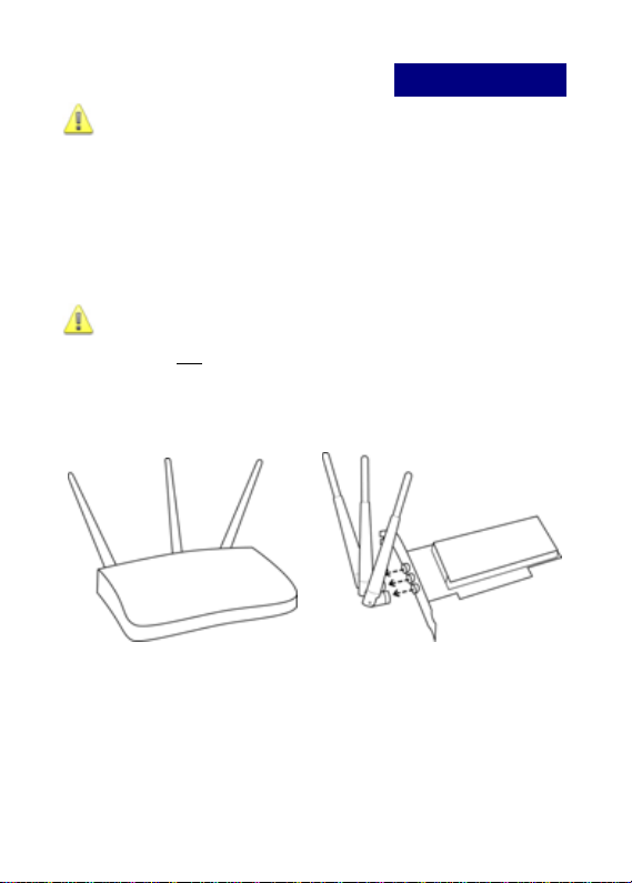
MIMO AP/ Router MIMO PCI Card
t
3
Page 5
SSttaarrtt IInnssttaalllliinngg yyoouurr 880022..1111nn//MMIIMMOO AAnntteennnnaa
RReellooccaatti
Model: EA-MARS
The antennas are not enclosed in the package.
In this case, you have to purchase proper antenna models
(Please contact with Edimax local distributors for more
information.) or use the antennas from your 802.11n/MIMO
devices.
For example, If EA-MARS is going to be used with your
802.11n/MIMO AP/ Router, the connection would be:
ioonn SSttaanndd
EA-MARS AP/ Router EA-MARS with
Notice:
Please make sure that the antennas of your 802.11n/MIMO
devices (Such as AP/ Router, PCI card) can be manually
detached (unscrewed) from the devices.
+ =
antennas
4
Page 6

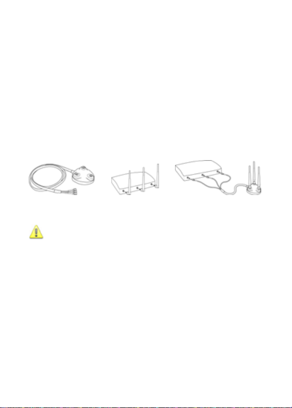
AAsssseemmbbllee tthhee aanntteennnnaass ttoo EEAA--MMAARRSS
Step 1.
Unscrew the antennas counterclockwise from the devices (see
below)
Step 2.
Screw the antennas clockwise onto the outer connectors of
EA-MARS until they are firmly attached.
5
Page 7

For PCI adapter For Router / AP
WWhheerree ccaann yyoouu llooccaattee tthhee ssttaanndd??
There are several positions
1. Desktop mount
2. Partition or metal surface mount
3. Ceiling mounts (without any tools)
4. Wall mounts with screws
1. Desktop stand
EA-MARS can helps you to relocate your antennas to a better
and optimal position to receive and transmit signals.
6
Page 8

2. Office partition or metal surface installation
EA-MARS is embedded with strong magnets to stick EA-MARS
to the metal walls or cabinets without extra tools or accessories.
Warning:
EA-MARS has 2 magnetic please keeps it away at least 6
inches from you PC in order not to crash the data or to make
other devices failed.
7
Page 9

Step 1.
Please note there are 2 plastic fasteners on the bottom of the
base. Push the fasteners downward with your forefingers and
disassemble the bottom cover from the stand like the direction
shown in the illustration
Use forefinger to loose both the hooks and push UPWARDS
with both your thumbs
Push upwards hardly until a opening click sound is heard
8
Page 10

Step 2.
Remove the bottom cover after both fasteners are released by
hands and turn the cover around. Re-assemble the cover by
clicking the cover back to position.
You can see 2 plastic hooks. These hooks could help you
flexible grabs onto the steel frames of your ceiling (see the
diagrams below).
9
Page 11

4. Wall installations (With screws and tools)
You need to use tools to complete this installation
The distance between screw holes is about 6cm, try to measure
and match this range before fix your screws on the wall.
10
Page 12

Screws installations
Lock the screw tightly and keep some margin spaces left (about
3 to 5mm) like the diagram below.
3mm
Therefore EA-MARS can be hanged onto the wall with both
screws.
11
Page 13

The antennas on the right and left side are for signal reception and
should be set perpendicular (90 degrees) to each other. The central
one is for signal transmission and should be pulled up about 45
degree. Please see the illustration below.
About antenna angle adjustment
Please position place the antenna vertically to the horizontal
surface (ceiling or floor), since the omni-directional antennas
best signal coverage is 360°. Do not put the antenna
perpendicular to the wall.
12
Page 14

Warning:
For better performance, both base stations and clients are
recommended to use EA-MARS with antennas
It should be no obstacles between the transmission areas. The
performance estimation is based on typical usage. The range is
varied with different site conditions.
13
 Loading...