

Page 1
880022..1111bb//gg W
wwiitthh W
WLLAANN
Wii--FFii
User’s Manual
UUSSBB AAddaapptteerr
DDeetteeccttoorr
Versio n: 1.1
(M ar 2006)
Page 2

COPYRIGHT
Copyright © 2004/2005 b y this comp an y. All righ ts reser ved. No p art of this
publ icat ion m ay b e reprodu ced , tr ans mitt ed, tran sc rib ed, stored in a ret rieval
system, or translated into any languag e or computer language, in any form or
by an y mean s, electr onic , mech anic al, mag n etic , opt ical, ch emical , m anual or
oth erwise, with ou t th e prior writ ten perm ission of th is com pan y
This c omp any makes n o repr esen tat ions or warran t ies, eit h er expres sed or
imp lied , with resp ect t o the c ontent s her eof and spec ifical l y discl aims an y
warran ties , mer ch ant ab ility or fitn ess f or any part icu l ar purp ose. An y sof tware
desc rib ed in th is manu al is s old or licen sed "as is" . Should th e prog rams
pr ove defec tive f ol lowin g th eir pu rch ase, the bu yer ( and not this comp an y, its
dist ribu t or, or its deal er) assumes the en tir e cost of all n ecess ary ser vicing ,
rep air, an d an y incid ent al or conseq uent ial damag es res ult ing fr om an y defec t
in the software. Further, this company reserves the right to revise this
publication and to make changes from time to time in the contents hereof
without obligation to notify any person of such revision or changes.
All brand and product names mentioned i n this manual are tr ademarks and/or regist ered
trademarks of their r espective holders.
Page 3

Fe d e r al Co m munic ation Co mm is s ion
Interference Statement
This equipment has been tested and found to comply with the limits for a
Clas s B d igital device, p u rsuan t to P art 15 of FCC Rul es. These l imits are
desig n ed to pr ovide reason ab l e pr otect ion agains t harm ful in ter feren ce in a
residential installation. This equipment generates, uses, and can radiate radio
freq u ency en ergy and , if not in stall ed and used in accor danc e with the
instructions, may cause harmful interference to radio communications.
However , t h ere is n o guaran tee t h at inter fer enc e will not occur in a par ticul ar
inst all ation . If this equ ipmen t d oes cau se harm ful inter fer enc e to radio or
tel evision rec ept ion , which can be d eter min ed by tur n ing the equ ipm ent of f
and on, th e user is enc ourag ed to t ry to corr ect th e in terf eren ce by one or
more of th e foll owing measu res :
1. Reori ent or r elocate the r ec eiv ing antenn a.
2. Increase t he separat ion between th e equip m ent and receiv er .
3. Conn ect th e equ ipm ent in to an out let on a circ uit d iff eren t from th at t o whic h th e
receiver is connected .
4. Cons ult the deal er or an exper ienced radio t ec hnician for help.
FCC Cau t ion
This eq u ipm ent mus t be inst all ed and op erat ed in accord an ce with provided
inst ru ction s and a minimu m 5 c m spacing mus t be provid ed b et ween
comp ut er m ounted antenn a and person ’s b ody (excl ud ing extr emit ies of
hand s, wrist and feet ) du ring wirel ess mod es of op erat ion .
This d evice comp l ies wit h P art 15 of the F CC Rul es. Op erat ion is subj ect t o
the following two conditions: (1) this device may not cause harmful
int erf eren ce, and (2) this device mu st accep t any in terf eren ce rec eived,
inclu d ing in terf eren ce th at may cau se und esir ed op erat ion.
Any ch ang es or m odif icat ions not expr essl y app roved b y the part y res pons ible
for c omp lian ce c ould void the au thorit y t o oper ate equ ip ment.
Federal Communication Commission (FCC) Radiation Exposure Statement
This equipment complies with FCC radiation exposure set forth for an
un cont roll ed environ men t . In ord er t o avoid th e poss ibil it y of exceedin g the
FCC rad io f req uency exposu re l imit s, hu man p roximity t o th e ant enna s hall
not be les s than 20c m (8 in ches) dur ing normal op eration .
Page 4

R&TT E Compl iance S t at ement
This eq u ipm ent comp lies with all the r equir emen ts of DIRECT IVE 199 9/5/ CE
OF THE EUROP EAN PAR LIAME NT AN D THE COU NC IL of Marc h 9, 1999 on
radio equipment and telecommunication terminal Equipment and the mutual
recognition of their conformity (R&TTE)
The R&T TE Direct i ve rep eal s an d repl aces in the d irec tive 98/13/ EEC
(Telec ommu n ication s Term inal Equ ip ment and S atell ite E arth S tat ion
Eq uipm ent ) As of April 8, 2000.
Safety
This eq u ipm ent is des igned with the ut most care f or the s afet y of those wh o
install and use it. However, special attention must be paid to the dangers of
elec tric sh ock and static elec tric ity wh en work ing wit h el ect ric al equip ment . All
gu idel ines of this and of th e compu t er manuf actu re mu st ther efore b e all owed
at al l tim es to en sur e the saf e use of the equ ipm ent.
EU Countries Intended for Use
The ETSI version of this device is intended for home and office use in Austria,
Bel giu m, Denmark , Finland , Fr ance, Germany , Gr eec e, Irelan d, Italy,
Luxemb our g , the Neth erl and s, Port ug al, Sp ain, Swed en, and the Unit ed
Kingdom.
The ETSI vers ion of th is device is al so au t hor ized for us e in EFTA memb er
stat es: Icelan d, Liech ten stein , Norway , an d Swit zerl and .
EU Countries Not intended for use
None.
Page 5

CONTENTS
1 Introd u ctio n .....................................................................................1
1.1 Features ...................................................................................................... 1
1.2 Specifications ............................................................................................. 1
1.3 Package Contents ........................................................................................ 2
2 The Outward Appearance of the Wi-Fi Detector ............................ 3
3 How to cha rge th e Wi -F i Detec tor ................................................... 4
4 How to us e th e Wi -F i Detec to r......................................................... 5
5 How to install the driver and utility ................................................7
6 How to configure the utility...........................................................12
6.1 W ireless Connection Status ........................................................................12
6.2 Gene ral Connection Setting........................................................................14
6.3 W EP and WPA Encryption.........................................................................17
6.3.1 WEP Settin g ............................................................................................................17
6.3.2 WPA Setting...........................................................................................................18
6.4 Advanc ed Settings......................................................................................20
6.5 Software AP Mode .....................................................................................21
6.5.1 AP Con ne c tion St atus ..............................................................................................21
6.5.2 AP General Connection Setting................................................................................23
6.5.3 MAC Address Filter.................................................................................................25
7 Troubleshooting.............................................................................27
Page 6

1 Introduction
Thank you for purchasing t his 802.11b/g WLAN USB adapter w ith Wi-Fi Detector . This
convenient de vice insta ntly detect s wireless hotspots anywhere. T he backlight LCM display
tells the user detailed informatio n about any detected hotspot . There’s no need to purchase
any battery because there is a rechargeable Li-Po lymer bat tery which recharges whene ver
the detector is inserted into any USB port .
This Wi-Fi detector also allows the user t o go online wirelessly and is designed t o comply
wit h IEEE 802.11g Wireless LA N standard. It is suitable for any laptop or desktop c omputer.
This detector supports 64/128/ 256-bit WEP data encryption that protect s your wireless
network f rom eavesdropping. It also supports W PA (Wi-Fi Protect ed Access) and WPA2 that
combi nes I EEE 802.1x and TKIP (Temporal Key Integr ity Protocol) technologies. Clie nt
users are required to authorize before acc essing to APs or AP Routers, and the data
transmitt ed in the netw ork is encrypted/decr ypted by a dynamically changed secret key.
This adapter has built-in AES e ngine which ensure the highest degree of security and
authe ntic ity f or d igital infor matio n and it is the mos t adva nced sol ut ion def ined by I EEE
802.11i for t he security in t he wireless network.
1.1 Features
• Complies with the IEEE 802. 11b and IEEE 802. 1 1g 2.4G Hz st andards.
• LCM displays: SSID, Signal Strength, Network type (802.11b/g), Network Mode
(infrastructure, Adhoc), operating channel, number of AP’s detected, battery strength,
Link/Act indicator)
• Up to 54Mbps high data transfer r ate.
• Support 64/128/256-bit WEP, WPA (TKIP with IEEE 802.1x) and WPA2 (AES with IEEE
802.1x) functions for high le vel of security.
• Supports Software AP function, which tur ns the wireless station into a wireless AP.
• Complies with IEEE 802.11d country r oami ng sta ndard.
• Support the most popular operating system: Wi ndows 98SE/Me/ 2000/ XP.
• Supports USB 2.0/1.1 interface.
• Portable and mini-si ze design.
• Suitable for Any Notebook or Desktop PC.
1.2 Specifications
• Standar d: IEEE 802.11g/b
• LCM Size: 96x32 with EL backlight
• Batter y: 4.2V Rechargeable Li-Poly mer Bat t er y
• Bus Type: USB 2.0 Type A
• Frequency Band: 2. 4000~ 2. 4835GHz (Industrial Scie ntific Medical Band)
• Modula tio n: OFDM with BPSK, QPSK, 16 Q AM, 6 4QAM (11g)
BPSK, Q PSK, CCK (11b)
1
Page 7

• Data Rate: 54/ 48/ 36/24/18/12/11/ 9/6/5.5/2/1Mbps auto fallback
• Security: 64/128/256-bit WEP Data Encryption, WPA (TKIP with IEEE 802.1x) and WPA2
(AES w ith IEEE 802.1x)
• Antenna: Internal Antenna
• Drivers: Windows 98SE/M e/ 2000/ XP/2003 Ser ver
• Transmit Power : 16dBm (Typical)
• Dimension: 14( H) x 28.5(W) x 91(D)
• Temperat ure: 32~ 140°F (0 ~60°C)
• Humidity: 0-85% ( NonConde nsing)
• Certif ic ation: FCC, CE
1.3 Package Contents
Before you begin the installation, ple ase check the items of your package. The package
should include the following it ems:
• One Wi-Fi Detector
• One Quick Guide
• One CD (Driver/ Utility/Manual)
If any of the above it ems i s missing, conta ct your suppli er as soon as possible.
2
Page 8
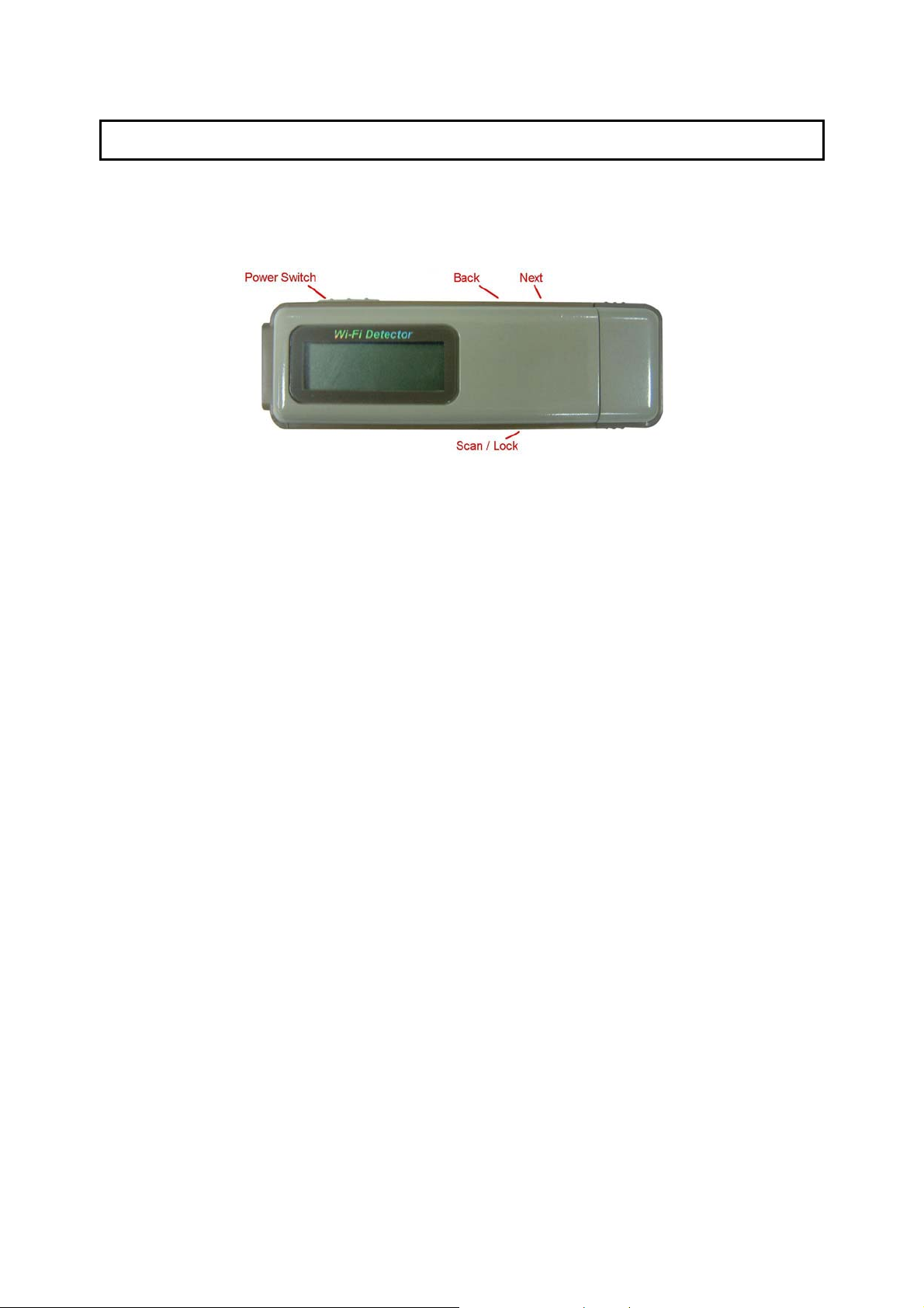
2 The Outward Appearance of the Wi-Fi Detector
3
Page 9
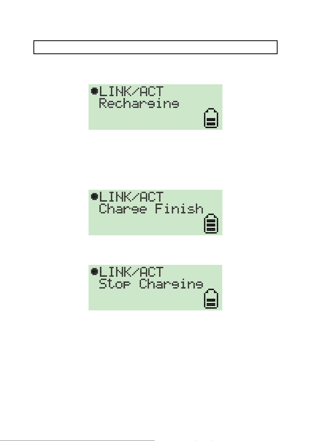
3 How to charge the Wi-Fi Detector
1. Remove the cap from the Wi-Fi Detector, slide the power switch to the “ON” position and
carefully insert the USB connector into any available USB port on your computer. You
will s ee t he rechar g ing sc ree n.
The bat ter y s tr ength ind icat or will b e animat ed while the Wi- Fi det ect or is being r ech arged.
The “Li nk/Ac t” ico n will b li nk whe n the Wi- F i det ect or is being used as a wir eles s USB
adapter t o surf the inter net.
2. Whe n the W i-F i det ect or is finis hed re c hargi ng it w ill a utomat ica lly s to p charg i ng the
bat ter y. W hen it is fi nis hed r echar gi ng t he batt er y yo u will see “Charg e F inis h” dis pla yed
on the L CM and t he ba tt er y str ength ind icat or will s to p bli nking.
3. If you slide the power sw itch to the “O FF” position when in recharging, the Wi-Fi
det ect or will sto p re chargi ng t he batt er y and yo u will s ee “ Sto p charg ing” disp lay ed o n
the LCM and t he bat te ry s trengt h indic at or w ill st op b linki ng.
4
Page 10
4 How to use the Wi-Fi Detector
1. Slide t he pow er s wit ch t o the “O N” posit io n, and a w elcom e s cre en will gr eet the user .
2. Af te r the we lcome s cre e n is display e d the W i-Fi de tec to r w ill auto mat ical ly e nter
scanning mode to det ect Wi-Fi signa ls.
In scanning mode the display will dis p lay t he tot al numbe r of bot h non-e ncry pte d and
encrypted Wi-Fi signals det ected.
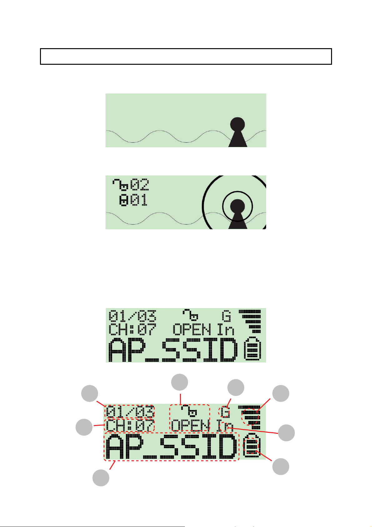
3. Once scanning mode is complete, t he detector will e nter it s st andar d disp lay mode.
The detector automat ically sort s the signa ls by the following criter ia:
Non-encrypt ed AP’s according to signal strengt h followed by encrypted AP’s accordi ng
to signal strength.
3
2
1
8
4
5
7
6
5
Page 11
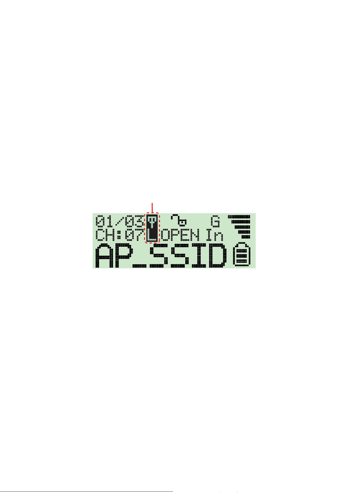
The Icons on the LCM display are displayed as follows:
1. Operat ing Cha nnel: Indicates the curre nt operating channel of t he detected Wi-Fi
signal.
2. Number of AP’s Detected: t he left digit ind icates which detected W i-Fi signal is
currently displayed a nd the right digit indicates the tot al amount of Wi-Fi signals
detected.
3. Encryption indicator: “WEP” for WEP encryption, “WPA” for WPA encryption, and
“WPA2” for WPA2 encryption, and “OPEN” indicates it is a non-encrypted signal.
4. “G” indicates the signal is a 802.11g w ireless signal. “B” indicates the signal is a
802.11b wir eless signa l.
5. Signal strength indicator with 5 bars indicating the signal strengt h.
6. “In” indicates the signal is an infrastruct ure mode signal, “Ad” indicates the signal
is an Ad hoc mode signal.
7. Battery indicator with 3 bars indicating battery power. When the indicator is
empty, please recharge the detect or by inserting it into a USB port.
8. SSID Indicator: Displays the SSID of the detected Wi-Fi signal, if the SSID is too
long t he SSID i ndic at or w ill sc roll t o dis play the co mplet e SSI D.
4. If the user wishes to detect a signal with a dedicated SSID, t he user simply has to hold
down the “scan” button for 4 seconds to enter “lock mode”. When the detector is in “lock
mode” an ic on with a capitalized “ L” appears in the upper middle corner of t he display.
In “lock mode” the detector constantly refr eshes the signal str ength so the user can
move around to find where the detected sig nal strength is the strongest.
Just hold down the “scan” button for 4 seconds again to unlock the “lock mode”.
6
Page 12

5 How to install the driver and utility
Before you proceed wit h the instal lation, please notice following descriptions .
Note1: Please do not install the USB adapter i nt o your computer before installi ng t he software
program from the CD .
Note2: The foll ow ing installat i on was operated i n Windows XP. (Procedure s are si mil ar f or
Window s 98SE/M e/2000/2003 Server.)
Note3: If you have installed the Wireless PC Card driver & utility before, please uninstall the
old version f irst.
Please follow below instr uctions to install the USB adapter.
I. Install the Configuration Ut ility
A. Insert the Installation CD to your CD-ROM Drive. Execute the “setup” program.
7
Page 13

B. If you want to install the software program in another location, click “Browse” and select
an alternative destination. Then, click “Next”.
C. Click “Continue A nyway” to finish the installatio n.
8
Page 14

II. Install the USB adapter
A. Plug the USB adapter into the USB port of your computer.
B. The “Fo und New Hardware Wizard” is display ed, select “ Install the softw are automatically
(Recommended)” and click “ Next”.
C. Click “Continue Anyway” and the system will sta rt to install t he USB adapt er .
9
Page 15

D. Click “Finish” to complete the installation.
III. Usin g the Configuration Utility
To setup the USB adapter, double-click the icon in the system tray.
For Windows XP, there is a “Windows Zero Co nfiguration Tool” by default for you to setup
wireless clients. If you want to use the Utilit y of the USB adapter , please follow one of the
ways as below .
10
Page 16

First Way
A. Double-click the utility
icon in the system tray.
B. Click “Y es” to use the
utility of t he USB adapter.
Second Way
A. Do uble- cl ick t he ico n.
B. Click “Advance”.
C. Unc heck “Use Windows to
configure my wireless
network settings”.
11
Page 17

6 How to configure the utility
The Configuratio n Utility is a powerf ul applicatio n that helps you configure the 802. 11g
Wireless LAN USB adapter and monitor t he link st atus during t he communicati o n process.
The Configuration Utility appears as an icon on the system tray of Windows while the
adapter is running. You ca n open it by double-c lick on the icon.
Right click the icon, there are some items for you to operate the config uration utility.
z Open Utilit y Window
Select “Open Utility W indow” to open the Configuratio n Utility tool.
z Exit ZDW lan
Select “ Exit ZDWla n” t o clos e t he Config ura tio n Util it y to ol.
Before using the utility, you have to know some restrictions of the utility.
1. I f you want to connect t o 11g (up to 54Mbps) network, please ensure to install the
adapter t o PC or laptop with USB 2.0 interf ace. This adapter runs at lower performance
while you connect it to the USB 1.1/1.0 por t of your comp uter instead.
2. This adapter will w or k in 11b mode when the network type is in Adhoc mode. It is
defines by Wi-Fi organizatio n. If you want to enable the data rate up to 54Mbps (11g),
please follow steps listed below .
A. Go to “Network Connections”.
B. Right Click the “Wireless Network Connection” a nd select “Propert ies”.
C. Fr om the pop-up screen, click “Config ure”.
D. Enter i nto “Advanced” page of t he “Properties” s creen.
E. Enable the sett ing of “IBSS_G _M ode” .
6.1 Wireless Connection Status
When you open the Configuration Utility, the system will scan all t he c hanne ls t o f ind all t he
access points/ stations within the accessible r ange of your adapter and automatically
connect to the wireless device wit h the hig hest sig nal strength. From the screen, you may
know all the infomration about the wireless co nnection.
12
Page 18

Parameter Description
Mode Stat ion – Set t he USB adapter a wireless clie nt.
Access Point – Turns the USB adapter t o functio n as a wireless
AP. Please refer to Section 6.5 for the AP settings.
Networ k Adapter Display the product informati on of the USB adapter.
Available Network Display all the SSID and Signal Strengt h of wireless stat ions
nearby. To re-survey t he available wireless devices please click
“Refresh”.
There are two ways t o automatica lly make the connectio n
between the USB adapter and the wireless stat ion on the list.
1. Do uble-c lic k t he wir eless st atio n on t he list dire ctly .
2. Select the station you intend to connect and then click
“Connect t his site“ .
Current Networ k Information Display the information about t he wireless networ k this adapter is
connecting to. The information incl udes Channel, Type, SSID, TX
Rate and Encrypt settings. Note: Please refer to Section 6.2 for
the description of each item.
More Sett ing For sett ing more f unctions including disable/ enable WEP and
Power Saving Mode, etc. Please refer to Section 6.2, 6.3 and 6.4.
Link Status Display the status of the wireless connectio n.
BSSID Displa y the MAC Ad dres s of t he netwo rk t he adapter is
connecting to.
13
Page 19

Parameter Description
Signal Strengt h This bar shows the signal str ength le vel. The higher perce ntage
shown in the bar, the more radio signal been recei ved by the
adapter. This indic ator helps to find the proper posit ion of the
wireless st ation for quality networ k operation.
Link Quality This bar indicates the quality of the link. The higher the
percentage, the bett er the quality.
TX Frame It shows the number of data f rames whic h are transmitted by t he
adapter successfully.
RX Frame It shows the number of data fr ames whic h are received by the
adapter successfully.
6.2 General Connection Setting
Click “More Setting”, users are allowed to setup the wireless connection setting, Encryption
Setting of the USB adapter and other advanced funct ions.
Parameter Description
General Connectio n Setting
Channel Select the number of t he radio cha nnel used for the netw orki ng.
The channel setting of the wireless stat ions within a netw ork
should be the same.
14
Page 20

Parameter Description
Tx Rate There are severa l optio ns including
Auto/1/2/5. 5/11/6/ 9/12/18/24/ 36/48/54Mbps f or you to select .
When t he “ Auto” is sele cte d, the dev ice w ill c hoose the most
suitable transmissio n rate automatically. The higher data rat e you
designated in the network , the shorter distance is allowed
between the adapter and the wireless st ations.
When the adapter w orks in 11b mode, the ma ximum data rate is
11Mbps so that t here are only “Auto/1/ 2/5.5/ 11Mbps” options yo u
can select.
SSID The SSID (up to 32 printable ASCII characters) is the unique
name identified in a WLAN. The ID prevents the unintentional
merging of tw o co-located WLANs.
You may specify a SSID for t he adapter and the n only the de vice
with the same SSID can inter co nnect to the adapter.
Any If “Any“ check box is enabled, the adapter w ill sur vey a nd co nnect
to one of the available wireless stat ions without checking the
consistency of cha nnel and SSID with the wireless station.
Network Type Ad-Hoc – T his mode enables wireless netw ork adapter s
interconnecting w ithout through AP or Router. Select this mode if
there is no AP or Router in the network.
Infrastruct ure – This operatio n mode requires the presence of an
802.11 Access Point. All communication is done via the Access
Point or Router.
Change/Apply Click “ Cha nge “ w ill enab le yo u to s et up the par amet ers of
“G eneral Co n nectio n Se tt ing“. In t he mea ntim e, t he butt o n will
change to “Apply“ for you to confirm your settings.
Encryption Setting In the block, users may enable/disable WEP a nd WPA encryption
within the network. Please refer to Section 6.3 for more
description.
15
Page 21

Parameter Description
Authenticatio n Mode This set ting has to be consistent wit h the wir eless networ ks that
the adapter intends to connect.
Open System – No authenticatio n is needed amo ng the wireless
network.
Shared Key – Only wireless statio ns us ing a shared key (WEP
Key identified) are allowed t o connect each other.
Auto – Auto switch the authenticatio n algorit hm depending on the
wireless networ ks that the adapter is connecting to.
WEP Encryption Key Setting Click t his button to setup the WEP key. Please refer to Section
6.3 for the details.
WPA Encryption Setting Click t his button to setup the WPA function. Please refer to
Section 6.3 for the details.
Profile
Profile Name You can save the network setting as a profile. To connect to the
network w ithout mak ing additional co nfiguration, yo u can load t he
profile.
Load Load the setting values from the file in the “Profile Name“ list. The
new se tt ings w ill be act i vated immed iat ely .
Save Current Input a file name and click “Save Current“ to write the current
setting values to be a profile in the “Profile Name“ list.
Delete Delete the profile you select.
Other
Advanced Setting... For more advanced setting, please click it. To know more of the
setting, please refer to Section 6.4.
Information To view the version of the driver, firmware and the MAC Address
of the adapter, click the butt on.
16
Page 22

6.3 WEP an d WPA En crypti on
WEP is an data e ncryptio n algorithm, which protect s Wireless LAN data in the network
against eavesdroppi ng. WEP has been found that it has some security problems. T he
adapter supports WPA (Wi-Fi Protec ted Access) that combines IEEE 802. 1 x and TKIP
(Temporal Key Integrity Prot ocol) technologies. Cl ient users are required to authorize befor e
accessing to Aps or AP Routers, and the data transmitt ed in the netw ork is
encrypted/decr ypted by a dynamically changed secr et key. This adapter is also built -in AES
engine which ensure the highest degree of security and authenticity for digital information
and it is t he most advanced so l utio n defi ned by IEEE 802. 11i for t he security i n the wireless
network.
6.3.1 WEP Setting
Parameter Description
Key Length You may select the 64-bit, 128-bit or 256-bit to encrypt
tr ansmit t ed dat a. Large r ke y lengt h will pr ovide hig her le vel of
securit y, but t he thro ug hp ut w ill be low er .
Default Key ID Select one of the keys (1~4) as the encrypt ion key.
Key For mat Hexdecimal – Only “A-F“, “a-f“ and “0-9“ are allowed to be set as
WEP key.
ASCII – Numerical values, characters or signs are allowed to be
the WEP key. It is more recognizable for user.
17
Page 23

Parameter Description
Key1 ~ Key4 The keys are used t o encrypt data tr ansmitt ed in the wireless
netw ork . Fill t he te xt bo x by f ollow i ng the rule s belo w.
64-bit – Input 10-digit Hex values or 5- digit ASCII values as the
encryption keys. For example: “0123456aef“ or “Guest“.
128-bit – Input 26-digit Hex val ues or 13-digit ASCII values as the
encryption keys. For example:
“012345678901234 56789abcdef “ or “administrator “.
256-bit – Input 58-digit Hex val ues or 29-digit ASCII values as the
encryption keys.
Cha nge/Ap ply Clcik “ Cha nge “ w ill enab le yo u to s et up the WEP k ey. In the
mea ntime, t he butt on w ill c hange t o “Ap ply“ fo r yo u to conf irm
your settings.
6.3.2 WPA Setting
The adapter can automatically det ect t he WPA setting of the AP which t he adapter intends
to connect to. To connect to the AP, you should setup the same setting with the AP.
There are two kinds of WPA mode: WPA and WPA-PSK. WPA is designed for enterpr ise
which requires a RADIUS Server and Certificat e Server for t he aut hentication. WPA-PSK is
a special mode designed for home and small business users w ho do not have access to
network authe ntication servers. In this mode, t he user manually enters the star ting
passwor d in their access poi nt or gateway , as well as in each wireless stat ions in t he
network. WPA takes over automatically from that point, keeping unauthorized users that
don't have the matching passwor d from joining the network, while e ncrypting the data
traveling betw een authorized devices.
18
Page 24

Parameter Description
Connect Informatio n It is the setting for WPA mode.
Protocol This adapter supports t wo kind of protoc ol for authentication
including TLS and PEAP. TLS a nd PEAP requires a certif icate
which is provided by the Certificat e Server. PEAP re quires a set
of user name and password in addition. To get the cert ificate and
the personal user name and password, please contact wit h your
administrat or.
TLS – Select a certificate from the “Certificat e“ list.
PEAP – Input the “User Name“ and “Passwor d“ and also select a
certificate from the “Certificate“ list.
User Name It is the sett ing for PEAP p rot ocol.
Passwor d It is the sett ing for PEAP p rot ocol.
Pre- shared Key It is the sett ing for W PA-PSK mode. I nput a 8 to 63 digits of ASCII
format t o be the password for the authenticatio n within the
network.
Cert if icat e All the availa ble cer tif icat es f or TLS or PEAP w ill disp lay in the
list. Please select a proper certificate f or the wireless
authentication.
19
Page 25

Parameter Description
WEP Key If the AP us es WEP data encryption function, pleas e clcik “WEP
KEY SETTING“ to setup the WEP key.
WEP KEY SETTING Setup the four sets of WEP key by clicking the button.
Cha nge/Ap ply Clcik “ Cha nge “ w ill enab le yo u to s et up the WPA s ett i ng. I n the
mea ntime, t he butt on w ill c hange t o “Ap ply“ fo r yo u to conf irm
your settings.
6.4 Advanced Settings
The “Advanced Sett ing” al lows user to enable/disable co untry roaming and power
consumption mode, set up the fragmentation threshold a nd RTS/CTS threshold of t he
adapter.
Parameter Description
User Interf ace Select the display language of the utility. Tw o lang uages are
enabled: Englis h and Chinese.
Cou ntry Roami ng IEEE 802. 11d (Country Roaming) is a standard that e nable the
wireless devices w ork at the proper transmission power and radio
channel regulated by the country where the user is located.
World Mode – Enable the country roaming functio n, the adapter
will f ollow t he set ting of the co n necti ng AP a uto matic al ly.
User Select – Disable the country roami ng function, users can
select the country where they are located. The channel sett ing
differs from countr y user selected.
20
Page 26

Parameter Description
Po w e r Co ns u mp t i o n Se t t ing Continuous Access Mode (C AM) – The adapter will alw ay s se t
in active mode.
Maximum Power-Sav ing Mode – E nable the adapter in the
power saving mode when it is idle.
Fast Power-Saving M ode – Enable the adapter in the power
saving mode when it is idle, but some components of t he adapter
is st ill ali ve. In t his mode , t he pow er c onsumpt io n is lar ger t han
“Max“ mode.
Fragementatio n Threshold The value defines the ma ximum size of packets , any packet size
larger than the value will be fragmented. I f you ha ve decreased
this value and experie nce high packet error r ates, you can
increase it again, but it w ill likely d ecr ease o veral l netw or k
perfor mance. Select a s etting withi n a range of 256 t o 2346 bytes.
Minor change is recommended.
RTS / CTS Threshold Minimum packet si ze required for an RTS/CTS (Request To
Send/Clear to Send). For packet s smaller than t his thres hold, an
RTS/CTS is not sent and the packet is transmitted directly to the
WLAN. Select a sett ing within a range of 0 to 2347 bytes. Minor
change is recommended
6.5 S oftware AP Mode
This adapter can run as a wireless AP. The relati ve configuratio ns of the AP inc ludi ng
channel, SSID, MAC Address Filter ing, WEP encryption and so on are descr ibed as follows.
6. 5 .1 A P Connect ion Sta tus
21
Page 27

Parameter Description
Mode Stat ion – Set t he USB adapter a wireless clie nt.
Access Point – Turns the USB adapter t o functio n as a wireless
AP.
Networ k Adapter Display the product informati on of the USB Adapter.
Connect Station List Display all the MAC Ad dresses of the wireless adapter s whic h are
connecting to t he AP.
Current Network Setting Display the connection setting of the current network. It includes
Cha nnel, SSID, WEP a nd TX Powe r Leve l.
More Sett ing For sett ing more f unctions including disable/ enable WEP, MAC
Address Filter and Bridge Adapter , et c. Please refer to Section
6.5.2.
TX Frame It shows the number of data f rames whic h are transmitted by t he
AP successf ully.
RX Frame It shows the number of data fr ames whic h are received by the AP
successfully.
22
Page 28

6.5.2 AP General Co nnecti o n Setti ng
Click “More Setting”, users are allowed to setup the AP connection setting, Encryption
Setting and other advanced f unctions.
Parameter Description
General Connectio n Setting
Channel Select the number of t he radio cha nnel used by the AP. The
wireless adapter s which connects to the AP should set up the
same channel.
Basic Rate Select the basic data transmissio n speed supports by the AP.
When the AP works in 11b mode, the ma ximum data rate is
11Mbps so that t here are two options incl uding “1, 2 Mbps“ and
“1, 2, 5.5, 11Mbps” you can select.
23
Page 29

Parameter Description
Tx Rate There are severa l optio ns including
Auto/1/2/5. 5/11/6/ 9/12/18/24/ 36/48/54Mbps f or you to select .
When t he “ Auto” is sele cte d, the dev ice w ill c hoose the most
suitable transmissio n rate automatically. The higher data rat e you
designated in the network , the shorter distance is allowed
between the adapter and the wireless st ations.
When the adapter w orks in 11b mode, the ma ximum data rate is
11Mbps so that t here are only “Auto/1/ 2/5.5/ 11Mbps” options yo u
can select.
SSID The SSID (up to 32 printable ASCII characters) is the unique
name identified in a WLAN. The ID prevents the unintentional
merging of tw o co-located WLANs.
The default SSID of the AP is WLAN_AP. Wireless adapter s
connect to the AP should set up the same SSID as the AP.
Hide SSI D If “Hide SSI D“ c heck bo x is e nabl ed, the AP w ill not appear in t he
site survey list of any wireless adapter s. It means Only the
wireless adapter s set the same SSID can connect to the AP. It
aviods the AP being connected by unauthori zed users.
Tx Power There are four levels for you to setup the transmission power of
the AP. The higher transmission power, the larger tr ansmiss ion
distance and wireless co verage.
Change/Apply Cl ci k “ C ha ng e “ w ill e nable y o u to se tup t he para meter s of
“G eneral Co n nectio n Se tt ing“. In t he mea ntim e, t he butt o n will
change to “Apply“ for you to confirm your settings.
WEP Enable or disable WEP encryption f unction. If the WEP function is
enabled, only wireless adapt ers wit h the same defa ult key and
WEP key setting can connect t o the AP.
Setting Click “Setting“ to setup the WEP key. Please refer to Section 6.3
for more description.
Authenticatio n Mode O pen System – No aut henticatio n is ne eded for connecti ng to the
AP.
Shared Key – Only wireless adapters using a shared key ( W EP Key
identified) are allowed to connecting to the AP.
24
Page 30

Parameter Description
Fragement The val ue defines the maximum size of pack ets, any packet size
larger than the value will be fragmented. I f you ha ve decreased
this value and experie nce high packet error r ates, you can
increase it again, but it w ill likely d ecr ease o veral l netw or k
perfor mance. Select a s etting withi n a range of 256 t o 2346 bytes.
Minor change is recommended.
RTS / CTS Minimum packet si ze required for an RTS/CTS (Request To
Send/Clear to Send). For packet s smaller than t his thres hold, an
RTS/CTS is not sent and the packet is transmitted directly to the
WLAN. Select a sett ing within a range of 0 to 2347 bytes. Minor
change is recommended.
Prea mble The prea mble de fi nes t he le ngt h of t he CRC bl ock f or
communication amo ng the wireless networ ks. There are two
modes including Long and Short . High network traf fic areas
should use the shorter pr eamble type.
MAC Address Filter This AP can protect from t he unaut horized users by MAC Address
filtering. Please ref er t o Section 6.5.3.
Bridge Adapter Wireless adapter s connect to the AP can access to the wired
network t hroug h the bridge adapter. Y ou can select an Et hernet
adapter in the list be the bridge between the wireless a nd wired
networks.
6.5.3 MA C A ddress Filte r
25
Page 31

Parameter Description
Filter Type Disable – Disable the MAC Addr ess filter f unctio n.
Accept – Only the wireless adapters w ith the MAC Address setup
in the table can connect to t he AP.
Reject – The wireless adapter s with the MAC Address setup in
the t able w ill be r ejec ted to connect t o the AP.
Filter MAC Address MAC Address is a unique identificatio n for hardware devices i n
the network . It is a 12-digit hexadeci mal values.
There are fifty set s of MAC Add res s can se tup i n the t able. Fill t he
MAC Addresses of w ireless adapter s you want to accept or reject
to access the AP in this table.
26
Page 32

7 Troubleshooting
This chapter pr ovides solutions to problems usually encountered d uring the installat ion and
operation of the adapter.
1. What is the IEEE 802.11g standard?
802.11g is the new IEEE sta ndar d for high-speed w ireless LAN communicatio ns that
provides for up to 54 Mbps data rat e in the 2.4 G Hz band. 802.11g is quick ly becomi ng
the next mainstream wireless LA N technology for t he home, office and public networks.
802.11g defines t he use of the same O FDM modulation technique specified i n IEEE
802.11a for the 5 GHz frequency band and applies it i n the same 2.4 GHz fr equency
band as IEEE 802. 11b. T he 802.11g standard req uires backward compatibility w ith
802.11b.
The standard specifica lly calls for :
A. A new physical layer for the 802.11 Medium Access Control (MAC) in t he 2.4 GHz
frequency ba nd, know n as the extended rat e PHY ( ERP). The ERP adds OFDM as
a mandatory new coding scheme for 6, 12 and 24 Mbps (mandator y speeds), and
18, 36, 48 and 54 Mbps (optional speeds). The ERP includes t he mod ulation
schemes found in 802.11b includi ng CCK for 11 and 5.5 Mbps and Barker code
modulatio n for 2 and 1 Mbps.
B. A prot ection mechanism called RTS/CTS t hat governs how 802.11g devices and
802.11b devices interoper ate.
2. What is the IEEE 802.11b standard?
The IEEE 802.11b Wireless LA N standard subcommittee, which formulates the
standard for t he industry. The objecti ve is to enable w ireless LAN hardwar e from
different manufactures to communicate.
3. What does IEEE 802. 11 featur e support?
The product support s the following IEEE 802. 11 functions:
z CSMA/CA plus Acknowledge Protoc ol
z Multi- Cha n nel Roam i ng
z Automatic Rate Selection
z RTS/CTS Feature
z Fragmentation
z Power Management
4. What is Ad-hoc?
An Ad- hoc integrated w ireless LAN is a group of computers, each has a Wireless LAN
adapter, Connected as an indepe ndent wireless LA N. Ad hoc wir eless LAN is
applicable at a depart mental scale for a branch or SOHO operation.
27
Page 33

5. What is Infrastr ucture?
An integr ated wir eless and wireless and wired LAN is called an Infrast ructure
configuration. Infrastructure is applicable to enterprise scale for wireless access to
central database, or wireless applicatio n for mobile workers.
6. What is BSS ID?
A specif ic Ad hoc LA N is call ed a Bas ic Ser vice Set (BSS) . Comp uter s in a BSS m ust
be configured with the same BSS ID.
7. What is WEP?
WEP is Wired Equivalent Privacy, a data pr ivacy mechanism based on a 40 bit shared
key algorithm, as descr ibed in the IEEE 802 .11 st andard.
8. What is TKIP?
TKIP is a quick-fix method to quickly overcom e the inherent weaknesses in WE P
security, especially t he reuse of encryption keys. TKI P is invo lved in the IEEE 802.11i
WLAN security st andard, and the spec ificatio n might be officially released by early
2003.
9. What is AES?
AES (Ad vanced E ncryp tio n Sta ndard) , a chip-b ased s ec urity, has bee n devel oped to
ensure the highest degree of security and authenticity for digital inform atio n, wherever
and however communicated or st ored, while making more ef ficient use of hardware
and/or softw are than pre vious encryptio n standards. It is also included in IEEE 802. 11 i
standard. Compare with AES, TKI P is a temporary prot ocol for replacing WEP security
until ma nufacturers imple me nt AES at t he hardw ar e level.
10. Can Wireles s products suppor t printer sharing?
Wireless products perf orm the same function as LAN products. Therefore, W ireless
products can work with Netware, Windows 2000, or other LAN operati ng systems to
support printer or file shari ng.
11. Would the infor mation be intercept ed whi le transmitt ing on air?
WLAN features two-fold protection in security. On the hardware side, as with Direct
Sequence Spread Spectr um technology, it has the inhere nt security f eature of
scrambling. On the software side, WLAN series offer the encryption function (WEP) to
enhance sec urity and Access Co ntrol. Users can set it up depending upon their needs.
28
Page 34

12. What is DSSS?What is FHSS? And what are t heir differences?
Frequency-hoppi ng spread-spectr um (FHSS) uses a narrowba nd carrier that changes
frequency in a patter n that is know n to both transmitter and receiver. Proper ly
synchroni zed, the net effect is to maintain a single logical channel. To a n unintended
receiver, FHSS appears t o be short-duration impulse noise. Direct-seq uence spreadspectrum (DSSS) generat es a redundant bit patt ern for each bit to be transmitted. This
bit patt ern is called a chip (or chipping code). The longer the chip is, the greater the
probability t hat the original data can be recovered. Even if one or more bits in the chip
are damaged during transmiss ion, stat istical techniques embedded in the radio ca n
recover the original data w ithout-the need for r etransmission. To an unintended
receiver, DSSS appears as low power wideband noise and is rejected (ignored) by
most narrowband receiver s.
13. What is Spread Spectr um?
Spread Spectrum technology is a w ideband radio frequency techniq ue developed by
the military for use in reliable, secure, mission-critical communication systems. It is
designed to tr ade off bandwidth efficiency for reliability , integrity, and sec urity. In other
words, more bandwidt h is consumed than in the case of narrowband transmission, but
the trade off produces a signal that is, in effect , louder a nd thus easier to detect ,
provided that the receiver knows the paramet ers of the spread- spectr um signal bei ng
broadcast. If a receiver is not tuned to t he right frequency, a spread –spect rum signal
looks like background noise. There are two main alternati ves, Direct Sequence Spread
Spect rum ( DSSS) a nd Freq uency Hoppi ng Spread Spectr um (FHSS).
29
 Loading...