

Page 1
Page 2

Copyright© by Edimax Technology Co, LTD. all rights reserved. No part of this
publication may be reproduced, transmitted, transcribed, stored in a retrieval system,
or translated into any language or computer language, in any form or by any means,
electronic, mechanical, magnetic, optical , chemical, manual or otherwise, without the
prior written permission of this company.
This company makes no representations or warranties, either expressed or implied,
with respect to the contents hereof and specifically disclaims any warranties,
merchantability or fitness for any particular purpose. Any software described in this
manual is sold or licensed "as is". Should the programs prove defective following
their purchase, the buyer (and not this company, its distributor, or its dealer) assumes
the entire cost of all necessary servicing, repair, and any incidental or consequential
damages resulting from any defect in the software. Further, this company reserves
the right to revise this publication and to make changes from time to time in the
contents hereof without obligation to notify any person of such revision or
changes.
Notice according to GNU/GPL-Version 2
This product includes software that is subject to the GNU/GPL-Version 2. You find
the text of the license on the product cd/dvd. The program is free software and
distributed without any warranty of the author. We offer, valid for at least three
years, to give you, for a charge no more than the costs of physically performing
source distribution, a complete machine-readable copy of the corresponding
source code. Please contact Edimax at: Edimax Technology co., Ltd, NO. 3,
Wu-Chuan 3rd RD Wu-Ku-Industrial Park, Taipei Hsien, Taiwan. R.O.C., TEL :
+886-2-77396888, FAX : +886-2-77396887, sales@edimax.com.tw
※ The product you have purchased and the setup screen may appear slightly
different from those shown in this QIG. For more detailed information about
this product, please refer to the User's Manual on the CD-ROM.
※ Software and specifications subject to change without notice. Please visit our web
site for the update.
※ All rights reserved. Trademarks or registered trademarks are the property of their
respective holders
1
Page 3

Introduction ................................................................................................................. 4
Chapter 1 .................................................................................................................. 18
1.1 Cable Modem ...................................................................................................... 30
1.2 Fixed-IP xDSL ..................................................................................................... 31
1.3 PPPoE ................................................................................................................ 32
1.4 PPTP .................................................................................................................. 34
1.5 L2TP ................................................................................................................... 36
1.6 Telstra Big Pond .................................................................................................. 38
Chapter 2 .................................................................................................................. 40
2.1 System ................................................................................................................ 42
2.1.1 Time Zone ........................................................................................................ 43
2.1.2 Password Settings ........................................................................................... 43
2.1.3 Remote Management ...................................................................................... 45
2.2 3G/3.5G .............................................................................................................. 47
( A ) Plug and play, no setup procedure required. .............................................. 47
( B ) PIN code or user name / password required: ............................................. 48
2.3 WAN .................................................................................................................... 48
2.3.1 Dynamic IP ....................................................................................................... 49
2.3.2 Static IP Address .............................................................................................. 50
2.3.3 PPPoE (PPP over Ethernet) ............................................................................ 50
2.3.4 PPTP ............................................................................................................... 50
2.3.5 L2TP ................................................................................................................ 50
2.3.6 Telstra Big Pond ............................................................................................... 50
2.3.7 DNS ................................................................................................................. 51
2.3.8 DDNS ............................................................................................................... 51
2.4 LAN ..................................................................................................................... 53
2.5 Wireless .............................................................................................................. 55
2.5.1 Basic Settings .................................................................................................. 56
2.5.2 Advanced Settings ........................................................................................... 58
2.5.3 Security ............................................................................................................ 60
2.5.3.1 WEP only ...................................................................................................... 60
2.5.3.2 802.1x only .................................................................................................... 62
2.5.3.3 802.1x WEP Static key .................................................................................. 63
2.5.3.4 WPA Pre-shared key ..................................................................................... 64
2
Page 4

2.5.3.5 WPA Radius .................................................................................................. 65
2.5.4 Access Control ................................................................................................. 65
2.6 QoS ..................................................................................................................... 69
2.7 NAT ..................................................................................................................... 72
2.7.1 Port Forwarding ............................................................................................... 74
2.7.2 Virtual Server ................................................................................................... 76
2.7.3 Special Applications ......................................................................................... 78
2.7.4 UPnP Settings .................................................................................................. 81
2.7.5 ALG Settings .................................................................................................... 82
2.7.6 Static Routing ................................................................................................... 83
2.8 Firewall................................................................................................................ 85
2.8.1 Access Control ................................................................................................. 86
2.8.2 URL Blocking ................................................................................................... 86
2.8.3 DoS (Denial of Service).................................................................................... 93
2.8.4 DMZ ................................................................................................................. 94
Chapter 3 .................................................................................................................. 95
3.1 Status and Information ........................................................................................ 96
3.2 Device Status ...................................................................................................... 98
3.3 System Log ......................................................................................................... 99
3.4 Security Log ...................................................................................................... 100
3.5 Active DHCP Client ........................................................................................... 101
3.6 Statistics ............................................................................................................ 102
Chapter 4 ................................................................................................................ 103
4.1 Configuration Tools ........................................................................................... 103
4.2 Firmware Upgrade ............................................................................................ 104
4.3 Reset ................................................................................................................ 105
Appendix A .............................................................................................................. 107
Glossary .................................................................................................................. 109
3
Page 5

Introduction
Thank you for purchasing Edimax 3G-6200n nLite wireless 3G broadband
router! This high cost-efficiency router is the best choice for Mobile / Small
office / Home office users, all computers and network devices can share a
single wireless 3G modem or xDSL / cable** modem internet connection at
high speed. Easy install procedures allows any computer users to setup a
network environment in very short time - within minutes, even inexperienced.
When the number of your computers and network-enabled devices grow, you
can also expand the number of network slot by simple attach a hub or switch,
to extend the scope of your network!
You can configure the router by running the Setup Wizard in the CD-ROM
provided in the package. The wizard provides quick setup for wireless
3G/3.5G Internet connection, Ethernet WAN Internet connection, SSID,
wireless security, firmware upgrade and changing router’s password. When
you start the Setup Wizard, you will get the following Welcome screen. Please
choose the language to start with and follow the easy steps in the Wizard. No
instruction for the Setup Wizard is given here.
If you lost the CD-ROM or you prefer the traditional web setup, please follow
the procedures in Manual to configure the router.
Note 1: Only one Internet connection (wireless 3G or xDSL/Cable) can be
used at the same time.
Note 2: To prevent the compatibility problem between 3G USB Modem cad
and 3G router, it is recommended that you upgrade the latest firmware
of 3G router from Edimax website http://www.edimax.com .
4
Page 6

Features
- Provides IEEE 802.11g/b wireless LAN access point
- Compatible with IEEE 802.11n standard with 150Mbps data rate
- High Internet access throughput
- Allow multiple users to share a single Internet connection
- Supports up to 253 network client users
- Provides one USB port for 3G wireless connection
- Internet Access via 3G modem or Cable or xDSL modem
- Access Servers on your LAN from the Public Network
- Equipped with four LAN ports (10/100M) and one WAN port (10/100M)
- Support DHCP (Server/Client) for easy setup
- Support advance features such as: special applications, DMZ, virtual
server, access control, firewall
- Allow you to monitor the router’s status such as: DHCP Client Log,
System Log, Security Log and Device/Connection Status
- Easy to use Web-based GUI for configuration and management
- Remote Management allows configuration and upgrades from a
remote site (over the Internet)
Minimum Requirements
- One External xDSL (ADSL) or Cable modem with an Ethernet port
(RJ-45)
- Network Interface Card (NIC) for each Personal Computer (PC)
- Computer with a Web-Browser (Internet Explorer 5.0 or higher /
Netscape Navigator 7.2 or higher)
Package Contents
- One Wireless 3G broadband router
- One Quick Installation Guide
- One CD-ROM (Wizard, Multi-languages QIG and User Manual)
- One Power Adapter
- Ethernet Cable
- Holding base
- Accessories
Note
The WAN “idle timeout” auto-disconnect function may not work due to
abnormal activities of some network application software, computer
virus or hacker attacks from the Internet. For example, some software
5
Page 7
sends network packets to the Internet in the background, even when
you are not using the Internet. So please turn off your computer when
you are not using it. This function also may not work with some ISP. So
please make sure this function can work properly when you use this
function in the first time, especially your ISP charge you by access time.
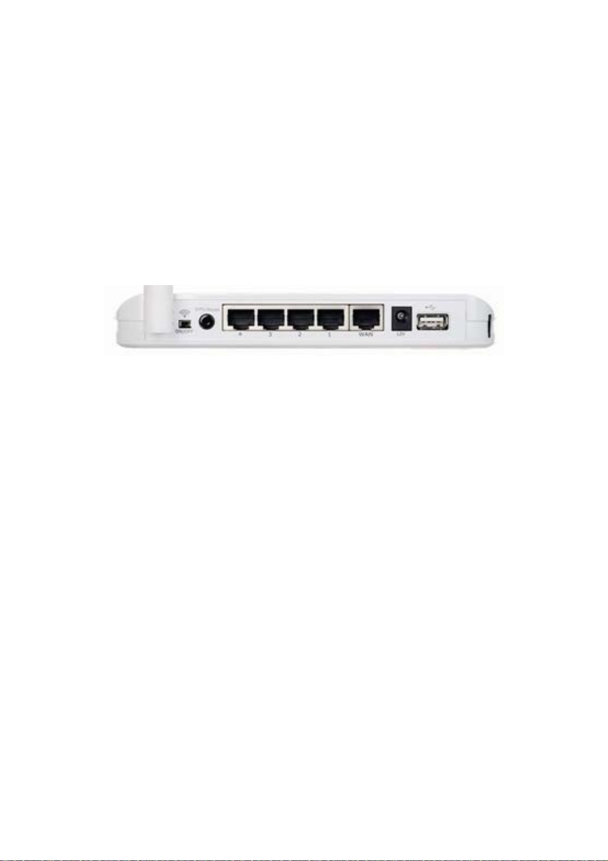
Back Panel
The diagram (fig1.0) below shows the broadband router’s back panel.
The router’s back panel is divided into four sections, LAN, WAN, USB,
and Reset:
Figure 1.0
1) Local Area Network (LAN)
The Broadband router’s 4 LAN ports are where you connect your LAN’s
PCs, hubs / switches etc.
2) Wide Area Network (WAN)
The WAN port connected to your xDSL or Cable modem which linked to
the Internet.
3) USB
The USB port allow you to share internet via 3G USB modem card.
4) WPS / Reset button
You can press the button 2~4 seconds to enable WPS for wireless
security.
When you experience some problem on using this router, or you forgot
your password, you can press the reset button for longer than 20
seconds and the router will reset itself to the factory default settings
(warning: your original configurations will be replaced with the factory
default settings)
5) Wireless on/off
You can enable/disable WiFi wireless signal via switch button.
6
Page 8
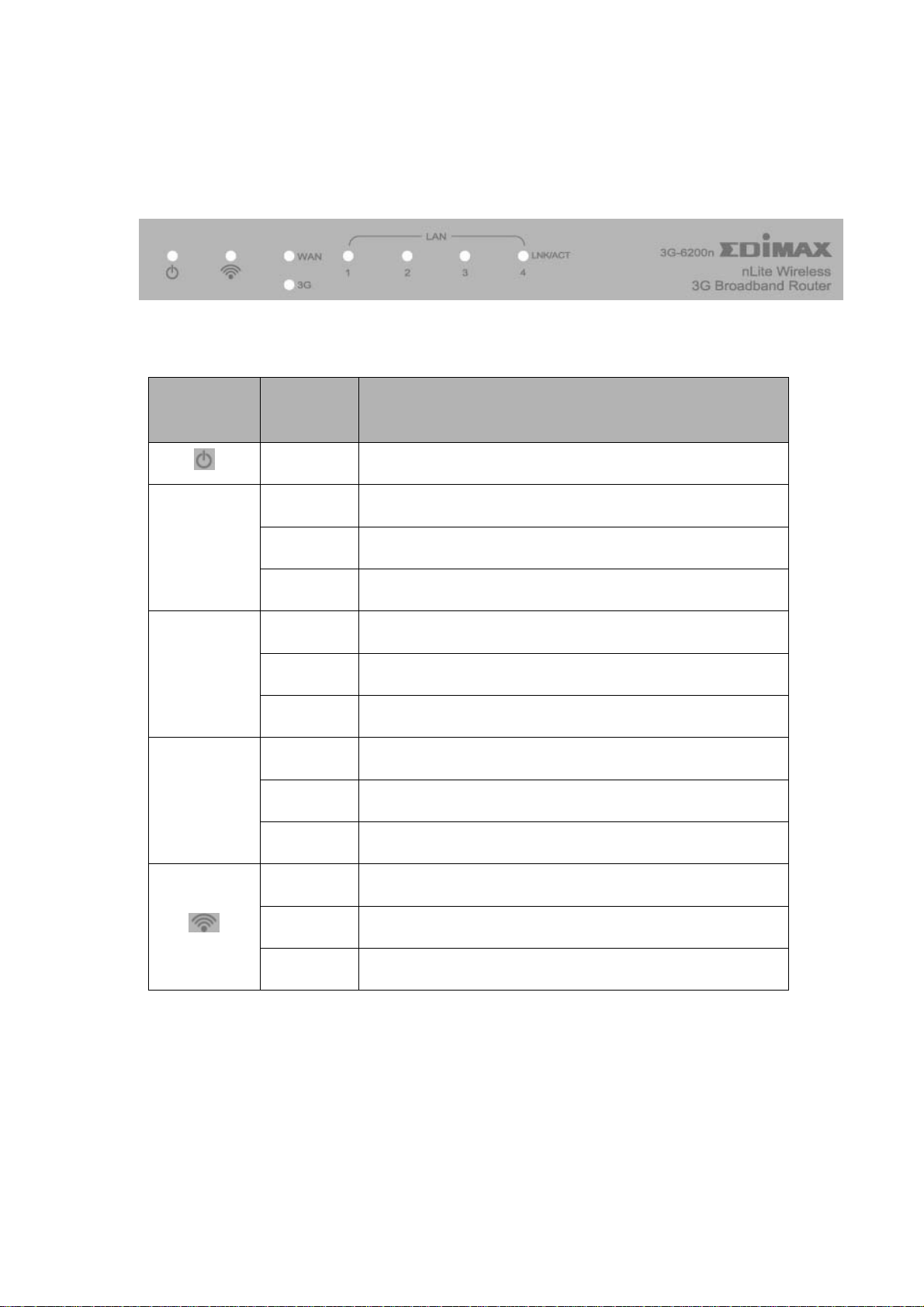
Front Panel
On the router’s front panel there are LEDs, which shows the status of
this router. Below is the list of each LED and its description.
Figure 1.1
LED
WAN
LNK/ACT
LAN
LNK/ACT
(Port 1-4)
3G
Light
Status
Description
ON Router is powered on
ON WAN is connected
Off WAN is unconnected
Flashing WAN port is sending / receiving data
ON LAN port is connected
Off LAN port is unconnected
Flashing LAN port is sending / receiving data
ON 3G USB modem is connected
Off 3G USB modem is not connected
Flashing 3G USB modem card is sending / receiving data
ON Wireless LAN has been activated
Off Wireless LAN is disabled
Flashing Wireless LAN is sending / receiving data
7
Page 9
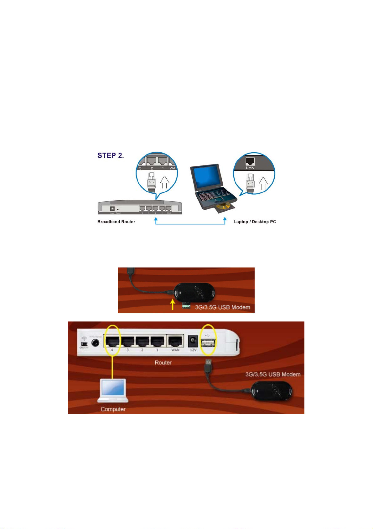
Setup Diagram
((AA)) 33GG//33..55GG MMooddeemm ccaarrdd iinnssttaallllaattiioonn::
If you have 3G/3.5G modem card and SIM card, please follow the following
instructions to establish connection
1. Connect power adapter to 3G-6200n
2. Connect another Ethernet cable from the any LAN ports (1~4) on router to
the
Ethernet socket on the PC
3. Insert SIM card into 3G/3.5G modem card, and connect the modem card
with one of USB port of 3G-6200n. The corresponding USB LED indicator
on 3G-6200n will light.
8
Page 10
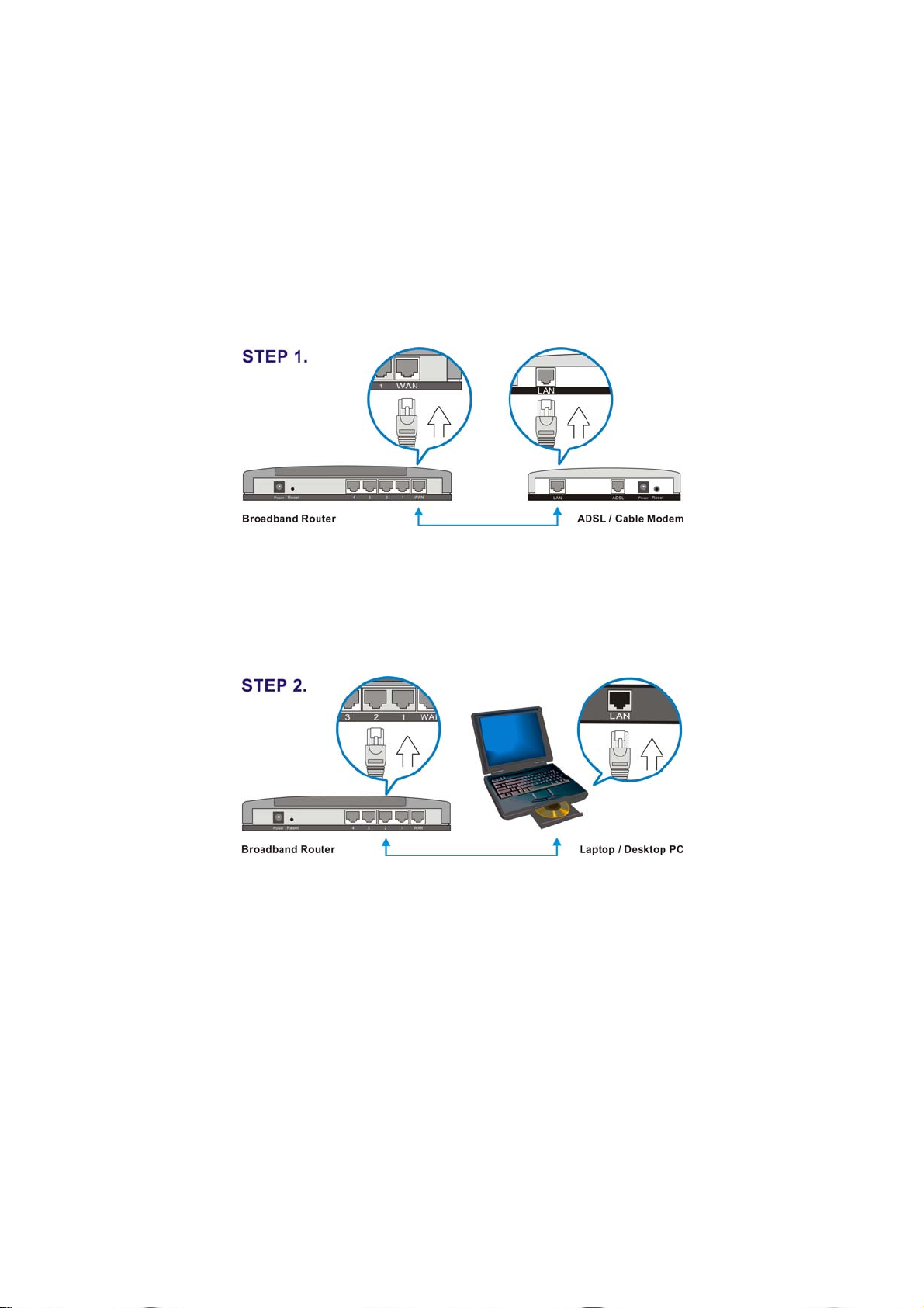
((BB)) CCaabblliinngg iinnssttaallllaattiioonn::
If you can also access Internet by xDSL/Cable modem, please follow the
following instructions:
1. Connect the Ethernet cable from the router’s WAN port to the LAN port of
the
modem.
2. Connect another Ethernet cable from the any LAN ports (1~4) on router to
the
Ethernet socket on the PC.
3. Check to make sure the router’s LINK LED is lit; to confirm the cable
connections are made correctly.
9
Page 11

Getting started
This is a step-by-step instruction on how to start using the router and
get connected to the Internet.
1) Setup your network as shown in the setup diagram above (fig 1.2).
2) You will need to set your LAN PC clients so that it can obtain an IP
address automatically. All LAN clients require an IP address. Just like
the mailing address in real world, it allows LAN clients to find one
another. (If you already configured your PC to obtain an IP automatically,
please jump to step 3, page 11)
Configure your PC to obtain an IP address automatically
Broadband router’s DHCP function is switched on by default; this
means that you can obtain an IP address automatically once you’ve
configured your PC to obtain an IP address automatically. This section
will show you how to configure your PC’s so that it can obtain an IP
address automatically for either Windows 95/98/Me, 2000 or NT
operating systems. For other operating systems (Macintosh, Sun, etc.),
follow the manufacturer’s instructions. The following is a step-by-step
illustration on how to configure your PC to obtain an IP address
automatically for:
2a) Windows 95/98/Me
2b) Windows XP
2c) Windows 2000, and
2d) Windows NT.
2a) Windows 95/98/Me
1. Click the Start button and select Settings, then click Control Panel.
The Control Panel window will appear.
2. Double-click Network icon. The Network window will appear.
3. Check your list of Network Components. If TCP/IP is not installed,
click the Add button to install it; if TCP/IP is installed, jump to step 6.
4. In the Network Component Type dialog box, select Protocol and click
Add button.
5. In the Select Network Protocol dialog box, select Microsoft and
TCP/IP and then click the OK button to start installing the TCP/IP
protocol. You may need your Windows installation CD to complete the
installation.
6. After installing TCP/IP, go back to the Network dialog box. Select
TCP/IP from the list of Network Components and then click the
Properties button.
7. Check each of the tabs and verify the following settings:
10
Page 12
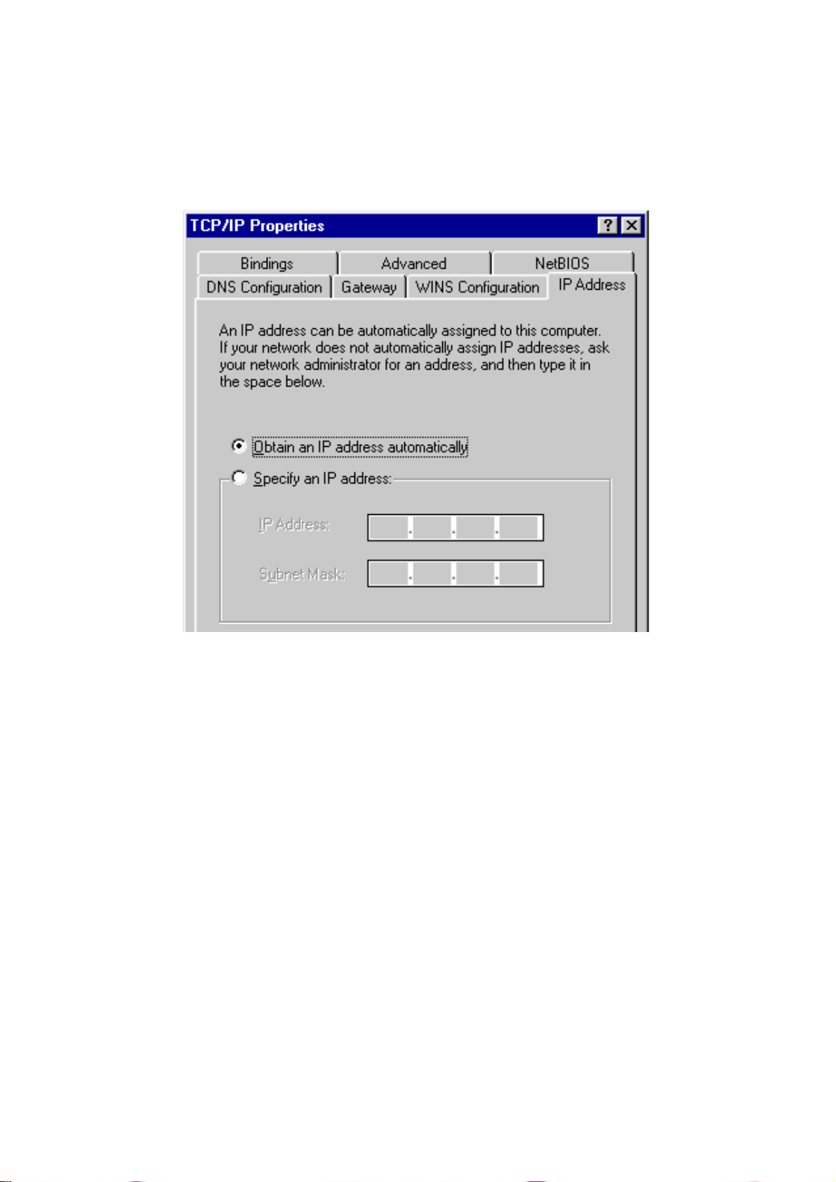
•Gateway: All fields are blank.
•DNS Configuration: Select Disable DNS.
•WINS Configuration: Select Disable WINS Resolution.
•IP Address: Select Obtain IP address automatically.
8. Reboot the PC. Your PC will now obtain an IP address automatically
from your Broadband Router’s DHCP server.
Note: Please make sure that the Broadband router is the only DHCP
server on your LAN.
Once you’ve configured your PC to obtain an IP address
automatically, please proceed to Step 3
2b) Windows XP
1. Click the Start button and select Settings, then click Network
Connections. The Network Connections window will appear.
2. Double-click Local Area Connection icon. The Local Area Connection
window will appear.
3. Check your list of Network Components. You should see Internet
Protocol [TCP/IP] on your list. Select it and click the Properties button.
4. In the Internet Protocol (TCP/IP) Properties window, select Obtain an
IP address automatically and Obtain DNS server address
automatically as shown on the following screen.
11
Page 13
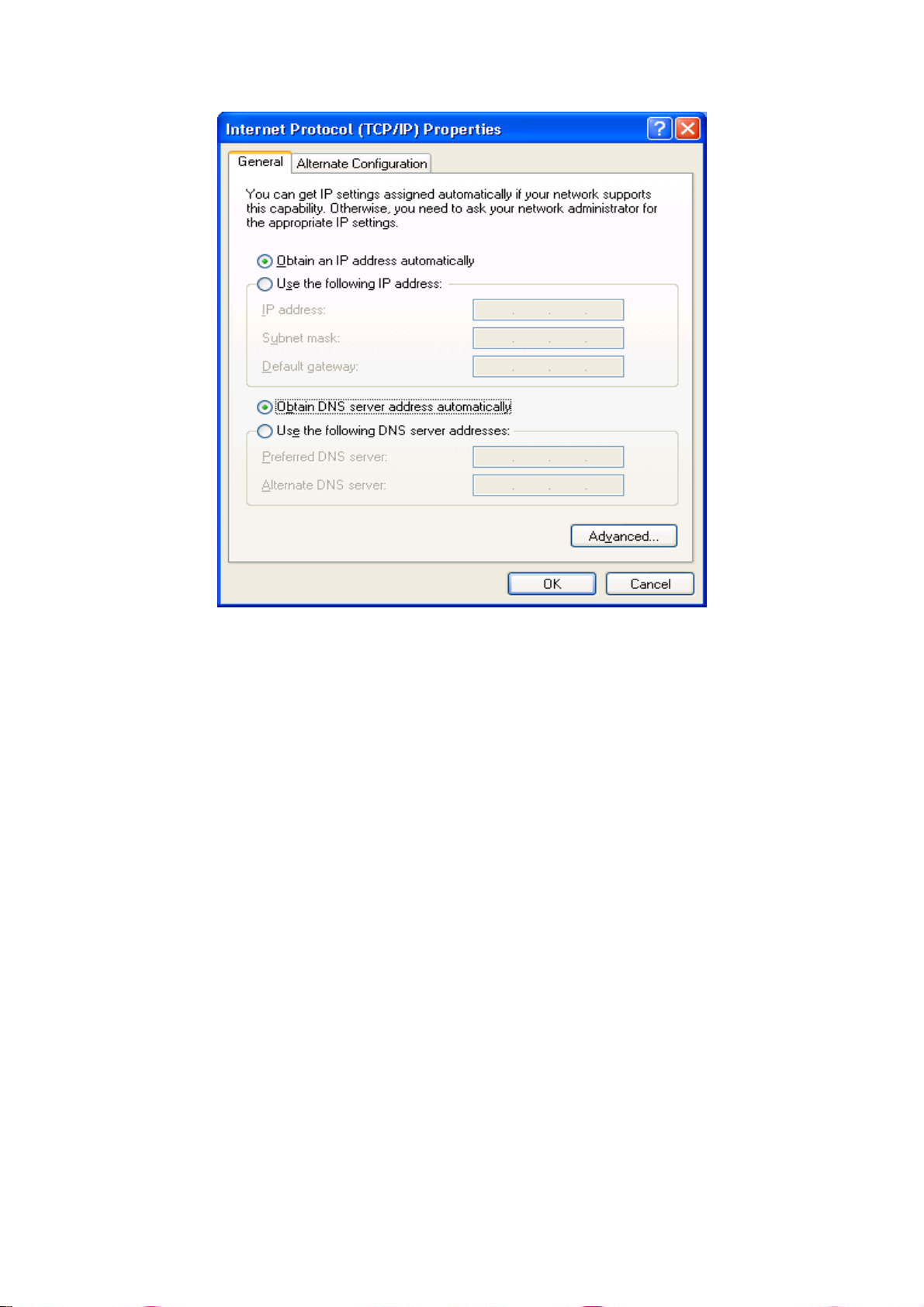
5. Click OK to confirm the setting. Your PC will now obtain an IP address
automatically from your Broadband Router’s DHCP server.
Note: Please make sure that the Broadband router is the only DHCP
server on your LAN.
Once you’ve configured your PC to obtain an IP address
automatically, please proceed to Step 3
2c) Windows 2000
1. Click the Start button and select Settings, then click Control Panel.
The Control Panel window will appear.
2. Double-click Network and Dial-up Connections icon. In the Network
and Dial-up Connection window, double-click Local Area Connection
icon. The Local Area Connection window will appear.
3. In the Local Area Connection window, click the Properties button.
4. Check your list of Network Components. You should see Internet
Protocol [TCP/IP] on your list. Select it and click the Properties button.
5. In the Internet Protocol (TCP/IP) Properties window, select Obtain an
IP address automatically and Obtain DNS server address
automatically as shown on the following screen.
12
Page 14
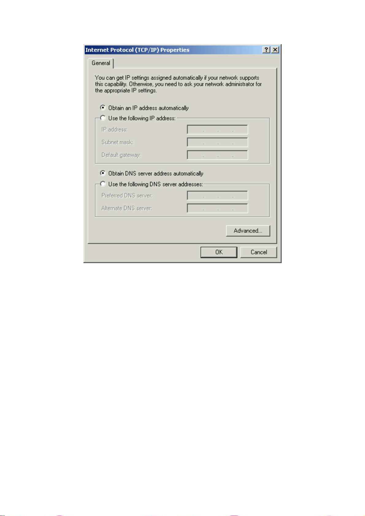
6. Click OK to confirm the setting. Your PC will now obtain an IP address
automatically from your Broadband Router’s DHCP server.
Note: Please make sure that the Broadband router is the only DHCP
server on your LAN.
Once you’ve configured your PC to obtain an IP address
automatically, please proceed to Step 3
.
2d) Windows NT
1. Click the Start button and select Settings, then click Control Panel.
The Control Panel window will appear.
2. Double-click Network icon. The Network window will appear. Select
the Protocol tab from the Network window.
3. Check if the TCP/IP Protocol is on your list of Network Protocols. If
TCP/IP is not installed, click the Add button to install it now. If TCP/IP
is installed, go to step 5.
4. In the Select Network Protocol window, select the TCP/IP Protocol
and click the Ok button to start installing the TCP/IP protocol. You may
need your Windows CD to complete the installation.
13
Page 15
5. After you install TCP/IP, go back to the Network window. Select
TCP/IP from the list of Network Protocols and then click the Properties
button.
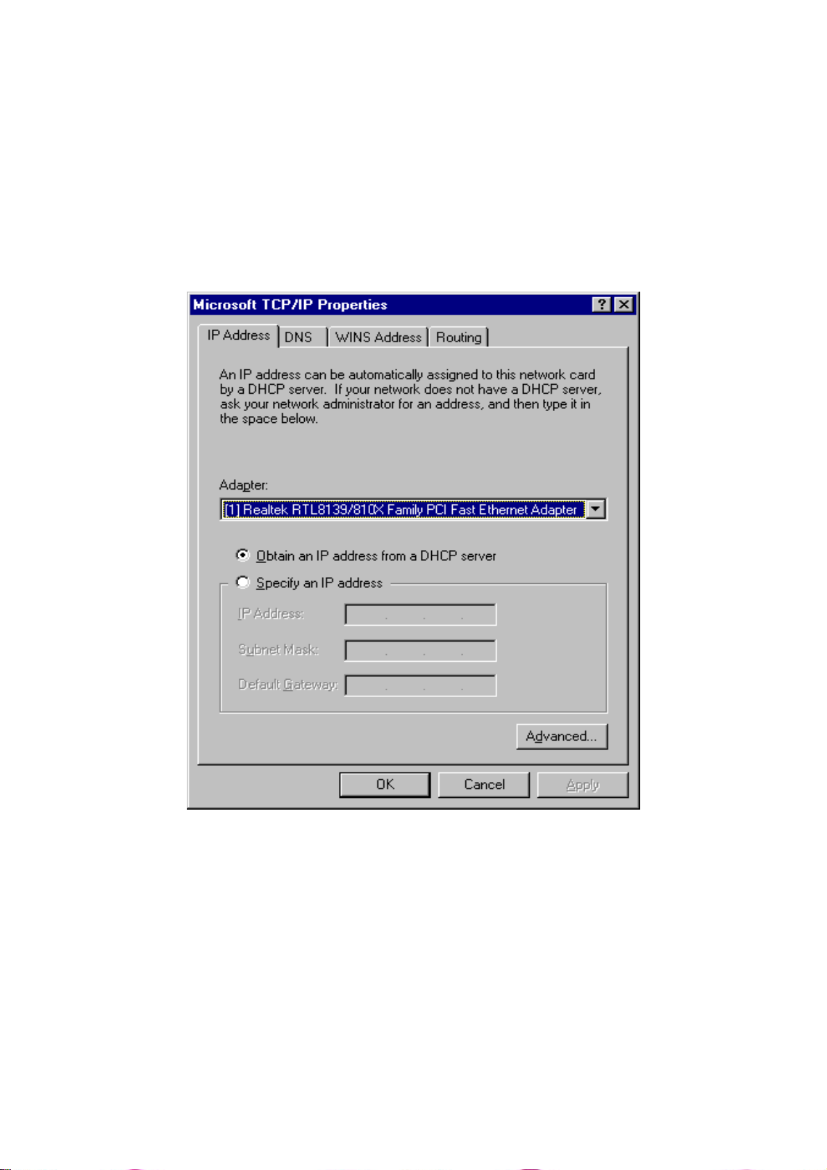
6. Check each of the tabs and verify the following settings:
• IP Address: Select Obtain an IP address from a DHCP server.
• DNS: Make all fields blank.
• WINS: Make all fields blank.
• Routing: Make all fields blank.
7. Click OK to confirm the setting. Your PC will now obtain an IP address
automatically from your Broadband Router’s DHCP server.
Note: Please make sure that the Broadband router is the only DHCP
server on your LAN.
Once you’ve configured your PC to obtain an IP address
automatically, please proceed to Step 3
3) Once you have configured your PCs to obtain an IP address
automatically, the router’s DHCP server will automatically give each of
your LAN clients an IP address. By default the Broadband Router’s
DHCP server is enabled so that you can obtain an IP address
14
Page 16
automatically. To see if you have obtained an IP address, see Appendix
A.
Note: Please make sure that the Broadband router’s DHCP server is
the only DHCP server on your LAN. If there is another DHCP on your
network, then you’ll need to switch one of the DHCP servers off. (To
disable the Broadband router’s DHCP server see chapter 2 LAN Port)
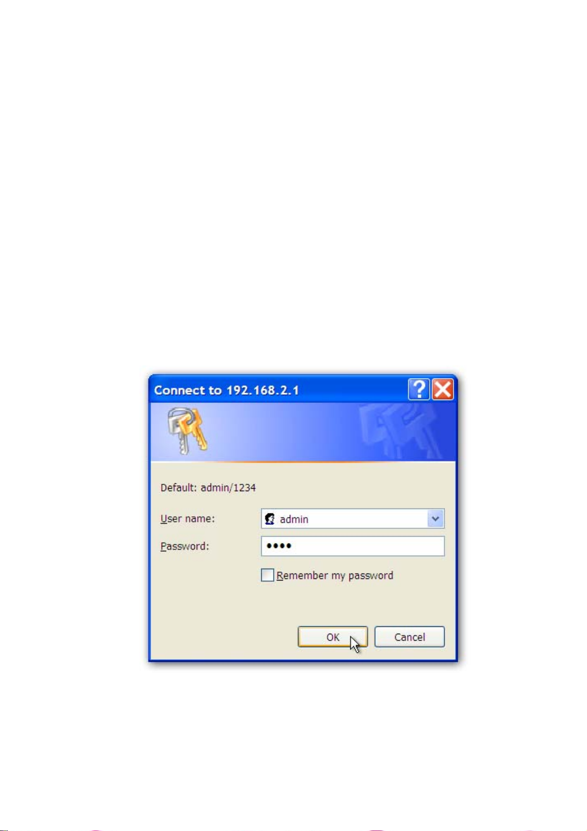
4) Once your PC has obtained an IP address from your router, enter the
default IP address 192.168.2.1 (broadband router’s IP address) into
your PC’s web browser and press <enter>
5) The login screen below will appear. Enter the “User Name” and
“Password” and then click <OK> to login.
Note: By default the user name is “admin” and the password is “1234”.
For security reasons it is recommended that you change the
password as soon as possible (in General setup / system /
password, see chapter 2)
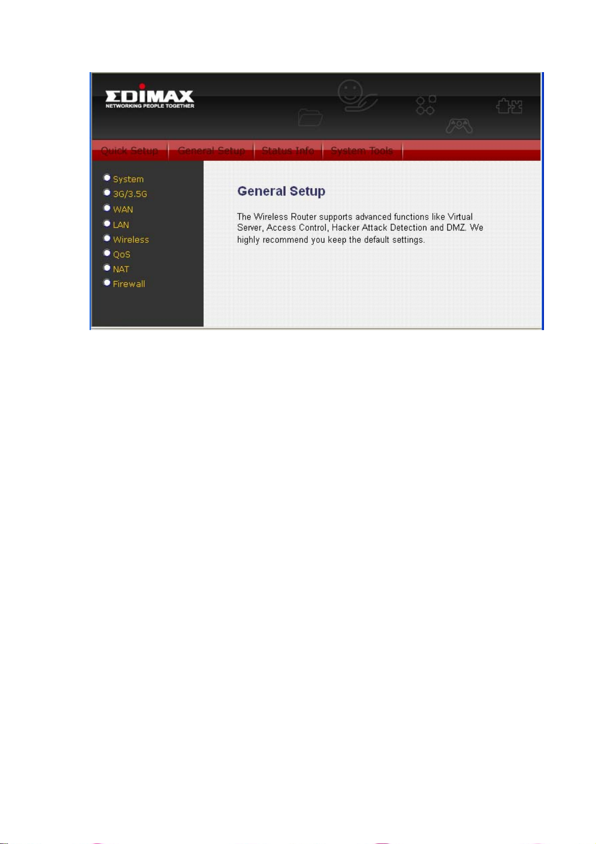
6) The HOME page screen below will appear. The Home Page is
divided into four sections, Quick Setup Wizard, General Setup,
Status Info and System Tools.
15
Page 17
Quick Setup Wizard (Chapter 1)
Select your Internet connection type and setup the configurations
needed to connect to your Internet Service Provider (ISP).
General Setup (Chapter 2)
This section contains configurations for the Broadband router’s
advanced functions such as: address mapping, virtual server, access
control, hacker attack prevention, DMZ, special applications and other
functions to meet your needs.
Status Info (Chapter 3)
In this section you can see the Broadband router's system information,
Internet Connection, Device Status, System Log, Security Log and
DHCP client information.
System Tools (Chapter 4)
This section contains the broadband router’s tool sets - tools include
configuration, firmware upgrade and Reset. Configuration tools allow
you to backup (save), restore, or restore to factory default configuration
for your Broadband router. The firmware upgrade tool allows you to
upgrade your Broadband router's firmware. The RESET tool allows you
to reset your Broadband router.
7) Click on Quick Setup Wizard (see chapter 1) to start configuring
settings required by your ISP so that you can start accessi ng the
Internet. The other sections (General Setup, Status Information and
16
Page 18

Tools) do not need to be configured unless you wish to implement /
monitor more advanced features/information.
Select the section (Quick Setup Wizard, General Setup, Status
Information and Tools) you wish to configure and proceed to the
corresponding chapter.
17
Page 19

Chapter 1
Quick Setup
The Quick Setup section is designed to get you using the broadband
router as quickly as possible. In the Quick Setup you are required to fill
in only the information necessary to access the Internet. Once you click
on the Quick Setup Wizard in the HOME page, you should see the
screen below.
Step 1) Time Zone
The Time Zone allows your router to base its time on the settings
configured here, this will affect functions such as log entries and firewall
settings.
Parameter Description
Set Time Zone
Time Server
Address
Daylight Savings
Times From
Times to
Click on NEXT to proceed to the next page (step 2): Broadband Type.
Select the time zone of the country you are living.
The router will set its time based on your selection
You can manually assign time server address if the
default time server dose not work
The router can also take Daylight savings into
account. If you wish to use this function, you must
check/tick the enable box to enable your daylight
saving configuration (below)
Select the period in which you wish to start using
daylight saving
Select the period in which you wish to stop using
daylight saving
18
Page 20

Step 2) 3G/3.5G Internet Configuration
3G-6200n supports most of 3G/3.5G modem cards, just connect the modem
card to the USB port of 3G-6200n and 3G-6200n will recognize it
automatically, no additional setup procedure required. However, some of
modem cards require PIN code or account / password (you have to use
3G-6200n’s web interface to input these information), and some modem cards
requires you to connect the modem card with your PC and install driver / utility
before you connect it with 3G-6200n (all PCs which need to access Internet
by 3G-6200n requires to perform this procedure once). If you still not able to
connect to Internet, please use wired Internet connection to access our
website :http://www.edimax.com/ ,download latest version of firmware and
upgrade 3G-6200n’s firmware. If you still not be able to get connected by your
3G/3.5G modem card, please contact your dealer of purchase and provide the
model name of the 3G/3.5G modem card you have, we’ll try our best to help
you to solve the problem.
Only one Internet connection (wireless / wired) can be used at the same time.
Wireless connection (3G/3.5G) will be selected first, and use wired Internet
connection as backup. Therefore, please DO NOT connect your 3G/3.5G
modem card with 3G-6200n, or your telecomm service provider may charge
you with high communication fee. For example, if you connect 3G/3.5G
modem card with 3G-6200n when you’re using wired Internet connection,
wired connection will be dropped and use 3G/3.5G wireless connection
instead. If 3G/3.5G wireless signal reception is poor and the connection can
not be restored within 60 seconds, 3G-6200n will use wired Internet
connection again, and will not switch back to wireless Internet connection
(This only happens with wired Internet connection is available. If wired
connection is unavailable, 3G-6200n will try to establish 3G/3.5G wireless
connection again and again). If you want to use 3G/3.5G wireless connection
again, you need to remove 3G/3.5G modem card from 3G-6200n and
reconnect it back after 5 seconds.
( A ) Plug and play, no setup procedure required.
Connect the USB 3G/3.5G modem card with 3G-6200n and make sure the
corresponding USB LED indicator of 3G-6200n lights up, then you can use the
web browser to access Internet.
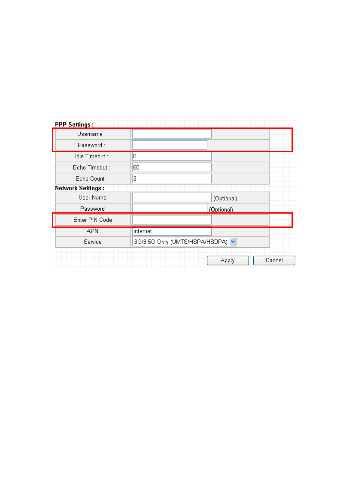
( B ) PIN code or user name / password required:
Please check the authentication method you want to use. Most of telecomm
service providers require you to input PIN Code, please check ‘SIM’ and input
the PIN code provided by telecomm service provider. Most of options listed
here are optional and you don’t have to provide those information if telecomm
service provider doesn’t provide you with those information.
19
Page 21

If telecomm provider provides you with username / password, please check
/User Name / Password box and input the user name / password provided by
telecomm service provider, then click ‘OK’ button. Wait for 1 minute (for
3G-6200n to reboot), then you can access Internet.
Please input User name & Password in “PPP Settings” and do not input them
in “Network Settings” unless your ISP ask you input them in both.
Note: Please choose “CDMA”, if your ISP use 3G CDMA system.
20
Page 22
( C ) Driver / Utility required on PC side
Some 3G/3.5G modem card does not work with instructions (A) or (B) listed
above (ex. BandLuxe C100S). You need to install 3G/3.5G modem card driver
/ utility on every PC which needs to access Internet first. After driver / utility
installation is complete, every PC will be able to access Internet via 3G/6200n.
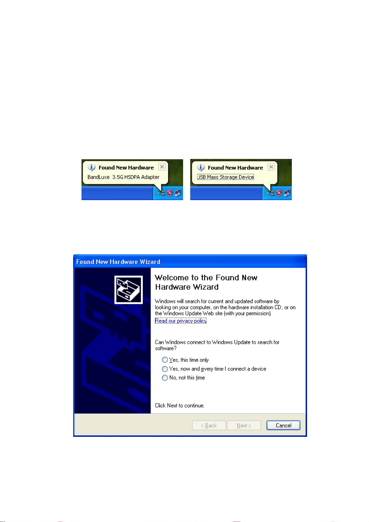
1. PlugintheBandLuxeC100SmodemcardtotheUSBportofyourcomputer.
2. ThesystemwilldetectthehardwareofC100SUSBadapterandalsothe
storageinsidetheadapter.
3. Pleaseclick“Cancel”toignorethemessageofthefoundnewhardware
wizard.
21
Page 23

4. Pleasegoto“Mycomputer”,youwillseetheBandLuxeC100S.Doubleclick
thedevice.
5. Theprograminsidetheadapterwillpreparetoinstallthedriverandutilityof
theadapter.
22
Page 24

6. Click“Next”.
7. Select“Iacceptthetermsinthelicenseagreement”andclick“Next”.
23
Page 25
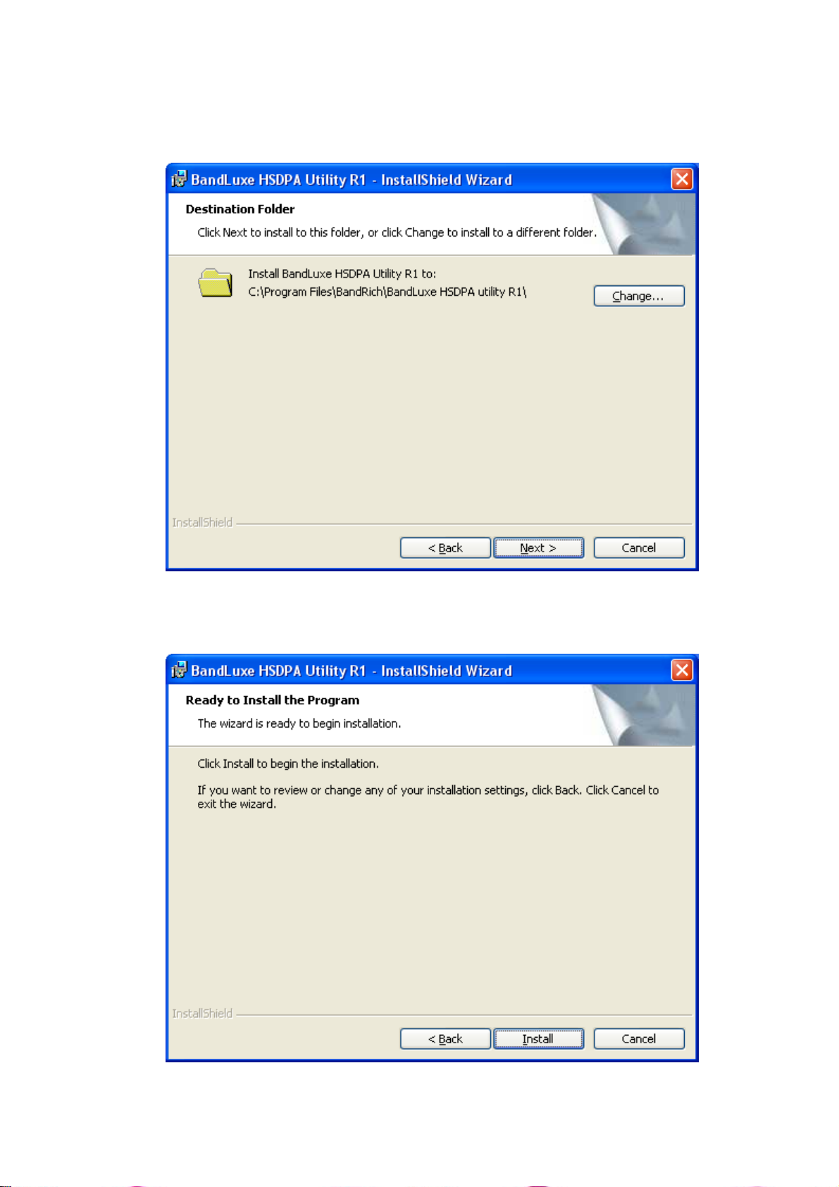
8. Ifyouwanttochangethedestinationfolder,pleaseclick“Change”.Click
“Next”tocontinue.
9. Click“install”.
24
Page 26
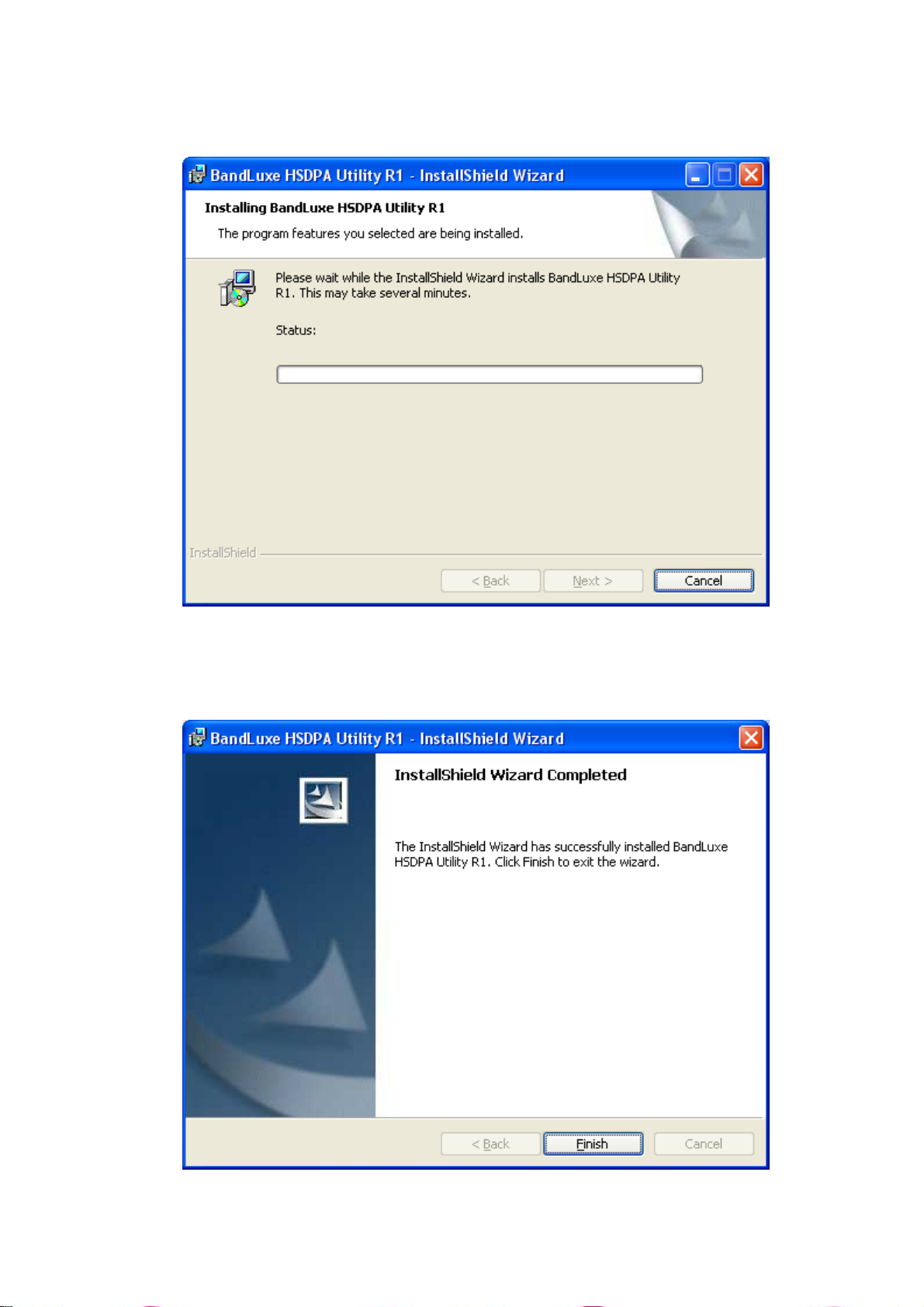
10. Thesystemisinstallingthedriverandutilityoftheadapter.
11. Installsuccessfully,click“Finish”toclosetheinstallwizard.
25
Page 27
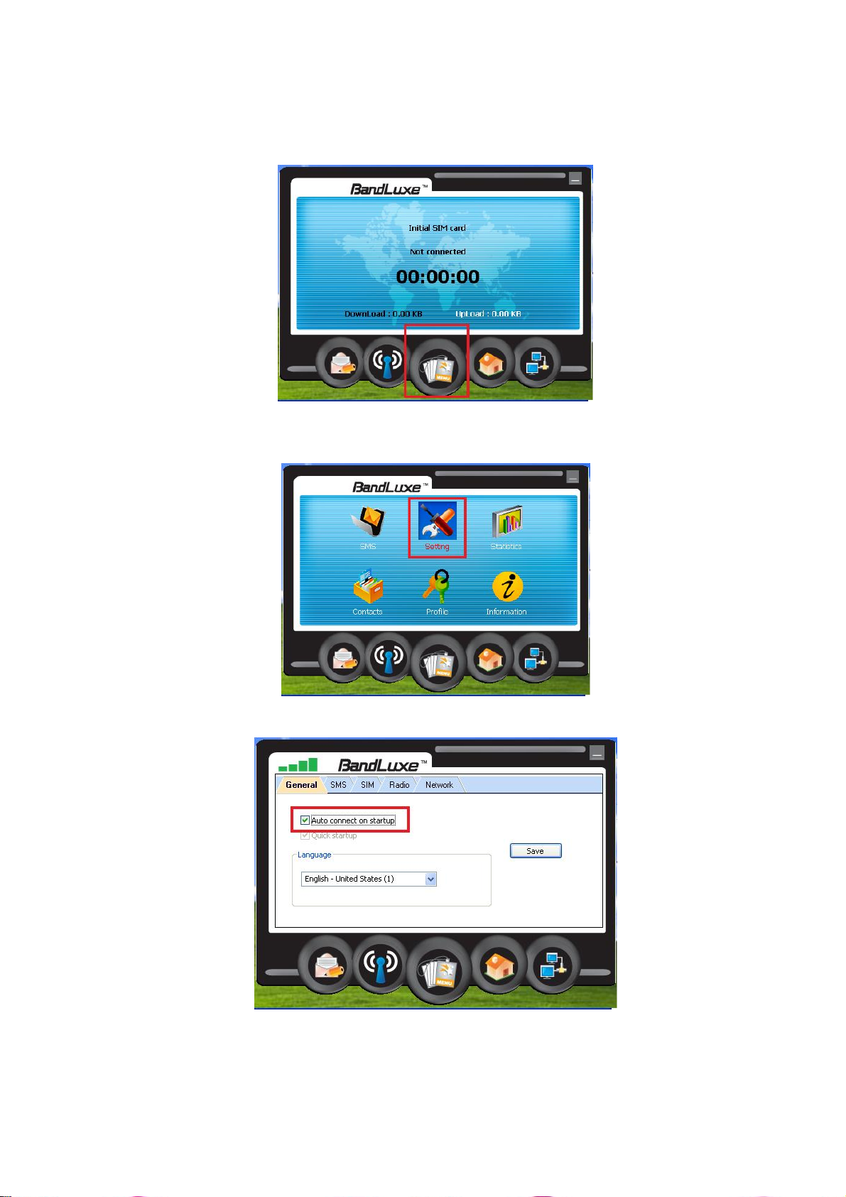
12. TheutilityofC100Swillstartupautomaticity.
Pleaseselectthe“MENU”
13. Click“Setting”.
14. Selectthe“Au to connectonstartup”.
26
Page 28
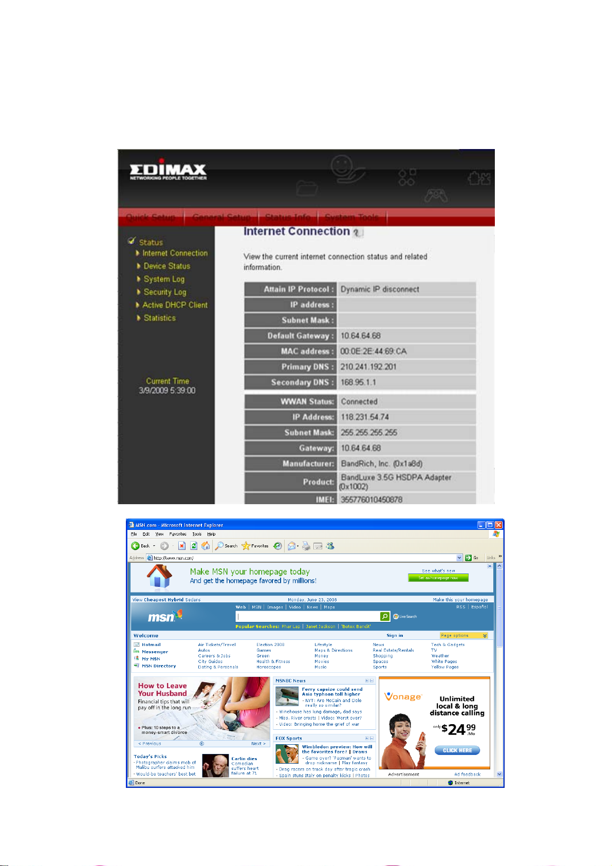
15. PlugintheC100SintotheUSBportofthe3Grouter.
16. TheUSBadapterwillgettheIPaddressfromISPautomatically.Yo u can
checktheStatusofthe3G‐6200nontheWebsite(ex:192.168.2.1).
17. NowyouareabletoconnecttoInternetsuccessfully.
27
Page 29
Note : If your SIM card requires entering the PIN code, please enter into the
web management of the 3G router. In WAN setting web page, select 3G/3.5G.
Enter the PIN code of the adapter.
Please input User name & Password in “PPP Settings” and do not input them
in “Network Settings” unless your ISP ask you input them in both.
28
Page 30
Step 3) Broadband Type ( Connect to Internet via Ethernet )
3G-6200n provides two types of Internet connection method: wireless
(3G/3.5G) or wired connection. You can access internet via USB 3G/3.5G
modem card, or via wired xDSL / cable modem connection. However, only
one connection method (wireless or wired) can be used at the same time.
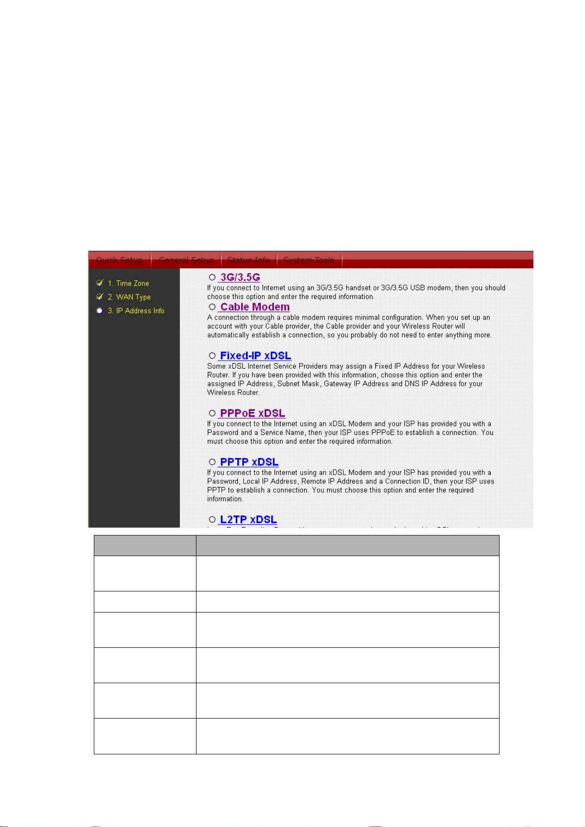
In this section you have to select one of six types of connections that
you will be using to connect your broadband router’s WAN port to your
ISP (see screen below).
Note: Different ISP’s require different methods of connecting to the
Internet, please check with your ISP as to the type of connection it
requires.
Menu Description
Cable Modem Your ISP will assign you with an IP address
automatically
Fixed-IP xDSL Your ISP gave you an IP address already
PPPoE xDSL Your ISP requires you to use Point-to-Point Protocol
over Ethernet (PPPoE)
PPTP xDSL Your ISP requires you to use a Point-to-Point
Tunneling Protocol (PPTP)
L2TP xDSL Your ISP requires you to use a Layer Two Tunneling
Protocol (L2TP)
Telstra Big Pond This Protocol only used for Telstra Big Pond Internet
service in Australia
29
Page 31

A
Click on one of the WAN type and then proceed to the manual’s relevant
sub-section (1.1, 1.2, 1.3, 1.4, 1.5 or 1.6). Click on Back to return to the
previous screen.
1.1 Cable Modem
Choose Cable Modem if your ISP will assign you with an IP address
automatically (i.e. DHCP). Some ISP’s may also require that you fill in
additional information such as host name and MAC address (see screen
below).
Note: The Host Name and MAC address section is optional and you
can skip this section if your ISP does not require these settings.
Parameters Description
If your ISP requires a Host Name, type in the host
Host Name
name provided by your ISP, otherwise leave it blank
if your ISP does not require a Host Name.
Your ISP may require a particular MAC address to
connect to the Internet. This MAC address is the
PC’s MAC address that your ISP had originally
connected your Internet connection to. Type in this
MAC address in this section or use the “Clone MAC
MAC Address
Address” button to replace the WAN MAC address
with the MAC address of that PC (you have to be
using that PC for the Clone MAC Address button to
work). To find out the PC’s MAC address see
ppendix A. (see Glossary for an explanation on
MAC address)
Click <OK> when you have finished the configuration above.
Congratulations! You have completed the configuration for the Cable
Modem connection. You can start using the router now, if you wish to
use some of the advance features supported by this router see chapter
2, 3, 4.
30
Page 32

1.2 Fixed-IP xDSL
Select Fixed-IP xDSL if your ISP has given you a specific IP address for
you to use. Your ISP should provide all the information required in this
section.
Parameters Description
IP address This is the IP address that your ISP has gi ven you.
Subnet Mask Enter the Subnet Mask provided by your ISP (e.g.
255.255.255.0)
DNS address This is the ISP’s DNS server IP address
Gateway IP
address
This is the ISP’s IP address gateway
Click <OK> when you have finished the configuration above.
Congratulations! You have completed the configuration for the
Fixed-IP x DSL connection. You can start using the router now, if
you wish to use some of the advance features supported by this
router see chapter 2, 3,
31
Page 33

1.3 PPPoE
Select PPPoE if your ISP requires the PPPoE protocol to connect you to
the Internet. Your ISP should provide all the information required in this
section.
Parameter Description
User Name
Password
Service Name
Enter the User Name provided by your ISP for the
PPPoE connection
Enter the Password provided by your ISP for the
PPPoE connection
This is optional. Enter the Service name of your ISP
when your ISP requires it, otherwise leave it blank.
This is optional. You can specify the ma ximum size
MTU
of your transmission packet to the Internet. Leave it
as it is if you to not wish to set the maximum packet
size. Please ask your ISP for detailed information.
If you select “Continuous”, the router will maintain
the connection to the ISP. If the WAN connection
drops, the router will reconnect to the ISP
automatically.
Connection Type
If you select “Connect On Demand”, the router will
auto-connect to the ISP when someone wants to
use the Internet and keep connected until the WAN
idle timeout. The router will drop the WAN
connection if the time period that no one is using the
32
Page 34

Internet exceeds the “Idle Time”.
If you select “Manual”, the router will connect to ISP
only when you click “Connect” manually from the
Web management interface. The WAN connection
will not disconnect because of idle timeout. If the
WAN line drops and connected at a latter time
again, the router will not connect to the ISP by itself.
You can specify an idle time (minutes) for the WAN
port. This means if no packets have been sent (no
one using the Internet) during this specified period,
the router will automatically disconnect the
connection to your ISP.
Note: This “idle timeout” function may not work due
to abnormal activities of some network application
Idle Time
software, computer virus or hacker attacks from the
Internet. For example, some software sends data to
the Internet in the background, even when you are
not using the Internet. So please turn off your
computer when you are not using it. This function
also may not work with some ISP. So please make
sure this function can work properly when you use
this function in the first time, especially when your
ISP charge you by the connection time.
Click <OK> when you have finished the configuration above.
Congratulations! You have completed the configuration for the PPPoE
connection. You can start using the router now, if you wish to use some
of the advance features supported by this router see chapter 2, 3, 4.
33
Page 35

1.4 PPTP
Select PPTP if your ISP requires the PPTP protocol to connect you to
the Internet. Your ISP should provide all the information required in this
section.
Parameter Description
Obtain an IP
address
Use the following
IP Address
The ISP requires you to obtain an IP address by
DHCP automatically before connecting to the
PPTP server.
The ISP gave you a static IP to be used to connect
IP address to the PPTP server
IP Address This is the IP address that your ISP gave you to
34
Page 36

establish a PPTP connection
Subnet Mask
Enter the Subnet Mask provided by your ISP (e.g.
255.255.255.0)
Gateway Enter the IP address of the ISP’s Gateway
Enter the User Name provided by your ISP for the
User ID
PPTP connection. Sometimes called as Connection
ID
Password
Enter the Password provided by your ISP for the
PPTP connection
If your LAN has a PPTP gateway, then enter that
PPTP Gateway
PPTP gateway’s IP address here. If you do not
have a PPTP gateway then enter the ISP’s
Gateway IP address, same as above
Connection ID
BEZEQ-ISRAE
This is the ID given by your ISP, and this is
optional.
Select this item if you are using the service
provided by BEZEQ in Israel.
If you select “Continuous”, the router will maintain
the connection to the ISP. If the WA N line breaks
down and links again at a latter time, the router will
reconnect to the ISP automatically; if you select
“Connect On Demand”, the router will auto-connect
to the ISP when someone wants to use the Internet
and keep connected until the WAN idle timeout.
The router will close the WAN connection if the
Connection Type
time period that no one is using the Internet
exceeds the “Idle Time”.
If you select “Manual”, the router will connect to ISP
only when you click “Connect” manually from the
Web management interface. The WAN connection
will not be disconnected because of idle timeout. If
the WAN line breaks down and got connected
again at a latter time, the router will not connect to
the ISP by itself.
Idle Time
You can specify an idle time threshold (minutes) for
the WAN port. This means if no packets has been
sent (no one using the Internet) throughout this
specified period, then the router will automatically
disconnect the connection to your ISP.
Note: This “idle timeout” function may not work due
to abnormal activities of some network application
35
Page 37

software, computer virus or hacker atta cks fro m th e
Internet. For example, some software sends
network packets to the Internet in the background,
even when you are not using the Internet. So
please turn off your computer when you are not
using it. This function also may not work with some
ISP. So please make sure this function can work
properly when you use this function in the first time,
especially your ISP charge you by time used
Click <OK> when you have finished the configuration above.
Congratulations! You have completed the configuration for the PPTP
connection. You can start using the router now, if you wish to use some
of the advance features supported by this router see chapter 2, 3, 4.
1.5 L2TP
Select L2TP if your ISP requires the L2TP protocol to connect you to the
Internet. Your ISP should provide all the information required in this
section.
Parameter Description
Obtain an IP The ISP requires you to obtain an IP address by
36
Page 38

address DHCP automatically before connecting to the L2TP
MAC Address
server.
Your ISP may require a particular MAC address to
connect to the Internet. This MAC address is the
PC's MAC address that you originally made your
Internet connection. Type in this MAC address in
this section or use the "Clone MAC Address" button
to replace the WAN MAC address with the MAC
address of that PC (you have to be using that PC
for the Clone MAC Address button to work). To find
out the PC's MAC address see Appendix A. (see
Glossary for an explanation on MAC address)
Use the following
IP Address
IP Address
Subnet Mask
The ISP gave you a static IP to be used to connect
to the L2TP server.
This is the IP address that your ISP has given you
to establish a L2TP connection.
Enter the Subnet Mask provided by your ISP (e.g.
255.255.255.0)
Gateway Enter the IP address of the ISP Gateway
Enter the User Name provided by your ISP for the
User ID
PPTP connection. Sometimes called a Connection
ID
Password
Enter the Password provided by your ISP for the
PPTP connection
If your LAN has a L2TP gateway, then enter that
L2TP Gateway
L2TP gateway IP address here. If you do not have a
L2TP gateway then enter the ISP’s Gateway IP
address above
This is optional. You can specify the maximum size
MTU
of your transmission packet to the Internet. Keep
default value if you do not wish to set a maximum
packet size.
Connection Type
If you select “Continuous”, the router will maintain
the connection to the ISP. If the WA N line breaks
down and links again at a latter time, the router will
auto-reconnect to the ISP. If you select “Connect On
Demand”, the router will connect to the ISP
automatically when someone wants to use the
Internet and keep connected until the WAN idle
timeout. The router will close the WAN connection if
the time period that no one is using the Internet
exceeds the “Idle Time”. If you select “Manual”, the
37
Page 39

Idle Time Out
router will connect to ISP only when you click
“Connect” manually from the Web user interface.
The WAN connection will not be disconnected due
to the idle timeout. If the WAN line breaks down and
latter links again, the router will not connect to the
ISP by itself.
The WAN “idle timeout" auto-disconnect function
may not work due to abnormal activities of some
network application software, computer virus or
hacker attacks from the Internet. For example,
some software sends network packets to the
Internet in the background, even when you are not
using the Internet. This function also may not work
with some ISP. So please make sure this function
can work properly when you use this function in the
first time, especially your ISP charge you by time
used. Due to the many uncontrollable issues, we do
not guarantee the WAN “idle timeout"
auto-disconnect function will always work. In order
to prevent from extra connection fee, please TURN
OFF THE ROUTER WHEN YOU ARE NOT USING
INTERNET.
Click <OK> when you have finished the configuration above.
Congratulations! You have completed the configuration for the L2TP
connection. You can start using the router now, if you wish to use some
of the advance features supported by this router see chapter 2, 3, 4.
1.6 Telstra Big Pond
Select Telstra Big Pond if your ISP requires the Telstra Big Pond
protocol to connect you to the Internet. Your ISP should provide all the
information required in this section. Telstra Big Pond protocol is used by
the ISP in Australia.
38
Page 40

Parameter Description
User Name Enter the User Name provided by your ISP for the
Telstra Big Pond connection
Password Enter the Password provided by your ISP for the
Telstra Big Pond connection
User decide
login server
Select if you want to assign the IP of Telstra Big
Pond’s login server manually.
manually
Login Server The IP of the Login Server.
Click <OK> when you have finished the configuration above.
Congratulations! You have completed the configuration for the Telstra
Big Pond connection. You can start using the router now, if you wish to
use some of the advance features supported by this router see chapter
2, 3, 4.
39
Page 41

Chapter 2
General Settings
Once you click on the General Setup button at the Home Page, you
should see the screen below.
If you have already configured the Quick Setup Wizard, you DO NOT
need to configure anything thing in the General Setup screen for you to
start using the Internet.
The General Setup contains advanced features that allow you to
configure the router to meet your network’s needs such as: Wireless,
Address Mapping, Virtual Server, Access Control, Hacker Attack
Prevention, Special Applications, DMZ and other functions.
Below is a general description of what advance functions are available
in this broadband router.
Menu Description
This section allows you to set the Broadband
System
router’s system time zone, password and remote
management administrator.
3G/3.5G
This section allows you to set Internet Connection
via wireless 3G USB modem.
This section allows you to select the connection
WAN
method in order to establish a connection with your
ISP (same as the Quick Setup Wizard section)
LAN
You can specify the LAN segment’s IP address,
subnet Mask, enable/disable DHCP and select an IP
40
Page 42

range for your LAN
Wireless Setup the wireless LAN’s SSID, WEP key, MAC
filtering.
QoS You can setup the QoS bandwidth control policy.
You can configure the Address Mapping, Virtual
NAT
Server and Special Applications functions in this
section. This allows you to specify what user/packet
can pass your router’s NAT.
Firewall The Firewall section allows you to configure Access
Control, Hacker Prevention and DMZ.
Select one of the above General Setup selections and proceed to the
manual’s relevant sub-section
41
Page 43

2.1 System
The system screen allows you to specify a time zone, to change the
system password and to specify a remote management user for the
broadband router.
Parameters Description
Time Zone
Password
Settings
Remote
Management
Select the time zone of the country you are living.
The router will set its time based on your selection
Allows you to define a password in order to access
the web-based management website.
You can specify a Host IP address that can perform
remote management functions.
Select one of the above three system settings selections and proceed to
the manual’s relevant sub-section
42
Page 44

2.1.1 Time Zone
The Time Zone allows your router to reference or base its time on the
settings configured here, which will affect functions such as Log entries
and Firewall settings.
Parameter Description
Set Time Zone
Time Server
Address
Select the time zone of the country you are living.
The router will set its time based on your selection.
The router default the “Time Server Address” is
“192.43.244.18”
The router can also take Daylight savings into
Daylight Savings
account. If you wish to use this function, you must
check/tick the enable box to enable your daylight
saving configuration (below).
Times From Select the period in which you wish to start using
daylight Saving.
Times to Select the period in which you wish to stop using
daylight Saving.
Click <Apply> at the bottom of the screen to save the configurations.
You can now configure other advance sections or start using the router.
2.1.2 Password Settings
You can change the password required to log into the broadband
router's system web-based management. By default, there is no
password. So please assign a password to the Administrator as soon as
possible, and store it in a safe place. Passwords can contain 0 to 12
alphanumeric characters, and are case sensitive.
43
Page 45

Parameters Description
Enter your current password for the remote
Current
Password
management administrator to login to your
Broadband router.
Note: By default there is NO password
New Password Enter your new password
Enter your new password again for verification
purposes
Confirmed
Password
Note: If you forget your password, you’ll have to
reset the router to the factory default (No
password) with the reset button (see router’s back
panel)
Click <Apply> at the bottom of the screen to save the configurations.
You can now configure other advance sections or start using the router.
44
Page 46

2.1.3 Remote Management
The remote management function allows you to designate a host in the
Internet the ability to configure the Broadband router from a remote site.
Enter the designated host IP Address in the Host IP Address field.
Parameters Description
This is the IP address of the host in the Internet that
will have management/configuration access to the
Broadband router from a remote site. This means if
you are at home and your home IP address has
been designated the Remote Management host IP
address for this router (located in your company
office), then you’ll be able to configure this router
from your home. If the Host Address is 0.0.0.0,
means anyone can access the router’s web-based
configuration from a remote location, if they know
the password.
Click the Enabled box to enable the Remote
Management function.
Host Address
Note: When you want to access the web-based
management from a remote computer, you must
enter the router’s WAN IP address (e.g. 10.0.0.1)
into your web-browser followed by colon and port
number 8080, e.g. 10.0.0.1:8080 (see below). You’ll
also need to know the password set in the
Password Setting screen in order to access the
router’s web-based management.
45
Page 47

Port The port number of remote management web
interface.
Enabled Select “Enabled” to enable the remote management
function.
Click <Apply> at the bottom of the screen to save the configurations.
You can now configure other advanced functions or start using the
router (with the advanced settings in place)
46
Page 48

2.2 3G/3.5G
3G-6200n provides two types of Internet connection method: wireless
(3G/3.5G) or wired connection. You can access internet via USB 3G/3.5G
modem card, or via wired xDSL / cable modem connection. However, only
one connection method (wireless or wired) can be used at the same time.
Related instructions will be given as follow.
3G-6200n supports most of 3G/3.5G modem cards, just connect the modem
card to the USB port of 3G-6200n and 3G-6200n will recognize it
automatically, no additional setup procedure required. However, some of
modem cards require PIN code or account / password (you have to use
3G-6200n’s web interface to input these information), and some modem cards
requires you to connect the modem card with your PC and install driver / utility
before you connect it with 3G-6200n (all PCs which need to access Internet
by 3G-6200n requires to perform this procedure once). If you still not able to
connect to Internet, please use wired Internet connection to access our
website :http://www.edimax.com/ ,download latest version of firmware and
upgrade 3G-6200n’s firmware. If you still not be able to get connected by your
3G/3.5G modem card, please contact your dealer of purchase and provide the
model name of the 3G/3.5G modem card you have, we’ll try our best to help
you to solve the problem.
Only one Internet connection (wireless / wired) can be used at the same time.
Wireless connection (3G/3.5G) will be selected first, and use wired Internet
connection as backup. Therefore, please DO NOT connect your 3G/3.5G
modem card with 3G-6200n, or your telecomm service provider may charge
you with high communication fee. For example, if you connect 3G/3.5G
modem card with 3G-6200n when you’re using wired Internet connection,
wired connection will be dropped and use 3G/3.5G wireless connection
instead. If 3G/3.5G wireless signal reception is poor and the connection can
not be restored within 60 seconds, 3G-6200n will use wired Internet
connection again, and will not switch back to wireless Internet connection
(This only happens with wired Internet connection is available. If wired
connection is unavailable, 3G-6200n will try to establish 3G/3.5G wireless
connection again and again). If you want to use 3G/3.5G wireless connection
again, you need to remove 3G/3.5G modem card from 3G-6200n and
reconnect it back after 5 seconds.
( A ) Plug and play, no setup procedure required.
Connect the USB 3G/3.5G modem card with 3G-6200n and make sure the
corresponding USB LED indicator of 3G-6200n lights up, then you can use the
web browser to access Internet.
47
Page 49

( B ) PIN code or user name / password required:
Please check the authentication method you want to use. Most of telecomm
service providers require you to input PIN Code, please check ‘SIM’ and input
the PIN code provided by telecomm service provider. Most of options listed
here are optional and you don’t have to provide those information if telecomm
service provider doesn’t provide you with those information.
If telecomm provider provides you with username / password, please check
/User Name / Password box and input the user name / password provided by
telecomm service provider, then click ‘APPLY’ button. Wait for 1 minute (for
3G-6200n to reboot)
2.3 WAN
Use the WAN Settings screen if you have already configured the Quick
Setup Wizard section and you would like to change your Internet
connection type. The W A N Settings screen allows to specify the type of
WAN port connect you want to establish with your ISP. The WAN
settings offer the following selections for the router’s WAN port,
Dynamic IP, Static IP Address, PPPoE, PPTP, L2TP, Telstra Big
Pond, DNS and DDNS.
48
Page 50

Parameters Description
Dynamic IP
Your ISP will assign you an IP address
automatically
Static IP Your ISP gave you an IP address already
PPPoE Your ISP requires PPPoE connection.
PPTP
Your ISP requires you to use Point-to-Point
Tunneling Protocol (PPTP) connection.
L2TP Your ISP requires L2TP connection.
Telstra Big Pond Your ISP requires Telstra Big Pond connection.
DNS You can specify a DNS server that you wish to use
You can specify a DDNS server that you wish to use
DDNS
and configure the user name and password
provided by you DDNS service provider.
Once you have made a selection, click <More Configuration> at the
bottom of the screen and proceed to the manual’s relevant sub-section
2.3.1 Dynamic IP
Choose the Dynamic IP selection if your ISP will assign you an IP
address automatically. Some ISP’s may also require that you fill in
additional information such as Host Name, Domain Name and MAC
address (see chapter 1 “Cable Modem” for more detail)
49
Page 51

2.3.2 Static IP Address
Select Static IP address if your ISP assigned you with a specific IP
address for you to use. Your ISP should provide all the information
required in this section. (See chapter 1 “Fixed IP” for more detail)
2.3.3 PPPoE (PPP over Ethernet)
Select PPPoE if your ISP requires the PPPoE protocol to connect you to
the Internet. Your ISP should provide all the information required in this
section. (See chapter 1 “PPPoE” for more detail)
2.3.4 PPTP
Select PPTP if your ISP requires the PPTP protocol to connect you to
the Internet. Your ISP should provide all the information required in this
section. (See chapter 1 “PPTP” for more detail)
2.3.5 L2TP
Select L2TP if your ISP requires the L2TP protocol to connect to the
Internet. Your ISP should provide all the information required in this
section. (See chapter 1 “L2TP” for detailed information)
2.3.6 Telstra Big Pond
Select Telstra Big Pond if your ISP requires the Telstra Big Pond
protocol to connect to the Internet. Your ISP should provide all the
information required in this section. Telstra Big Pond protocol is used by
the ISP in Australia. (See chapter 1 “Telstra Big Pond” for more detail)
50
Page 52

2.3.7 DNS
A Domain Name System (DNS) server is like an index of IP addresses
and Web addresses. If you type a Web address into your browser, such
as www.router.com, a DNS server will find that name in its index and
the matching IP address. Most ISPs provide a DNS server for speed
and convenience. If your Service Provider connects you to the Internet
with dynamic IP settings, it is likely that the DNS server IP address is
provided automatically. However, if there is a DNS server that you
would rather use, you need to specify the IP address of that DNS server
here.
Parameters Description
DNS address
Secondary DNS
Address
(optional)
Click <Apply> at the bottom of the screen to save the configurations.
You can now configure other advance sections or start using the router
(with the advanced settings in place)
Fill in the ISP’s DNS server IP address; or you can
specify your own preferred DNS server IP address
This is optional. You can enter another DNS
server’s IP address as a backup. The secondary
DNS will be used when the above DNS fail.
2.3.8 DDNS
DDNS allows you to map the static domain name to a dynamic IP
address. You must get an account, password and your static domain
51
Page 53

name from the DDNS service providers. This router supports DynDNS,
TZO and other common DDNS service providers.
Parameters Default Description
Enable/Disable Disable Enable/Disable the DDNS function
of this router
Provider Select a DDNS service provider
Domain name Your static domain name that use
DDNS
Account/E-mail
Password/Key
The account that your DDNS
service provider assigned to you
The p assword you set for the
DDNS service account above
Click <Apply> at the bottom of the screen to save the configurations.
You can now configure other advance sections or start using the router.
52
Page 54

2.4 LAN
The LAN Port screen below allows you to specify a private IP address
for your router’s LAN ports as well as a subnet mask for your LAN
segment.
Parameters Default Description
This is the router’s LAN port IP
IP address 192.168.2.1
address (Your LAN clients default
gateway IP address)
IP Subnet Mask 255.255.255.0 Specify a Subnet Mask for your LAN
53
Page 55

802.1d
Sp anning Tree
Disabled
DHCP Server Enabled
segment
If 802.1d Spanning Tree function is
enabled, this router will use the
spanning tree protocol to prevent
from network loop happened in the
LAN ports.
You can enable or disable the DHCP
server. By enabling the DHCP server
the router will automatically give your
LAN clients an IP address. If the
DHCP is not enabled then you’ll have
to manually set your LAN client’s IP
addresses; make sure the LAN Client
is in the same subnet as this
broadband router if you want the
router to be your LAN client’s default
gateway
Lease Time
IP Address Pool
Domain Name
When enabled, DHCP service will
temporarily give your LAN clients an
IP address. In the Lease Time setting
you can specify the time period that
the DHCP lends an IP address to
your LAN clients. The DHCP will
change your LAN client’s IP address
when this time period is reached
You can select a particular IP address
range for your DHCP server to issue
IP addresses to your LAN Clients.
Note: By default the IP range is from:
192.168.2.100 to 192.168.2.200. If
you want your PC to have a
static/fixed IP address then you’ll
have to choose an IP address outsi de
this IP address Pool.
You can specify a Domain Name for
your LAN.
Click <Apply> at the bottom of the screen to save the configurations.
You can now configure other advance sections or start using the router.
54
Page 56

2.5 Wireless
Wireless Access Point builds a wireless LAN and can let all PCs
equipped with IEEE 802.11b or 801.11g wireless network adaptor
connect to your Intranet. It supports WEP and WPA2 encryption to
enhance the security of your wireless network.
Parameters Default
Description
Enable or
disable
Wireless
Enable
You can select to enable or disable the
wireless access point module of this router.
module
function
Click <Apply> at the bottom of the screen to save the configurations.
You can now configure other advance sections or start using the router.
55
Page 57

2.5.1 Basic Settings
You can set parameters that are used for the wireless stations to
connect to this router. The parameters include Mode, ESSID, Channel
Number and Associated Client.
Parameters Default Description
Mode
It allows you to set the AP to AP, Bridge or
WDS mode.
It allows you to select the wireless band:
802.11(B+G+N),802.11(B+G),802.11b and /
Band
or 802.11g. You can select B+G+N mode to
allow all 802.11b,802.11g and 802.11n
clients to connect to this wireless access
point.
This is the name of the wireless access
ESSID default
point. All devices in the same wireless LAN
should have the same ESSID.
Channel
Number
11
The wireless channel used by the wireless
access point. All devices in the same
wireless LAN should use the same channel.
If you want to combine more than one
network, you have to set this access point to
MAC
address
“AP Bridge-Point to Point mode”, “AP
Bridge-Point to Multi-Point mode” or “AP
Bridge-WDS mode”. You have to enter the
MAC addresses of other access points
which will join the same wireless network.
Set Security Click the “Set Security” button, and then a
56
Page 58

“WDS Security Settings” will pop up. You
can set the security parameters used to
bridge access points together here, when
you set your AP in AP Bridge mode. You can
refer to section 4.3 “Security Settings” for
detailed instructions.
Click <Apply> at the bottom of the screen to save the configurations.
You can now configure other advanced sections or start using the router
(with the advanced settings in place)
57
Page 59

2.5.2 Advanced Settings
You can set advanced wireless LAN parameters of this router. The
parameters include Authentication Type, Fragment Threshold, RTS
Threshold, Beacon Interval, preamble Type, etc. You should not change
these parameters unless you know their function and effects.
Parameters Description
Fragment
Threshold
RTS
Threshold
Beacon
Interval
"Fragment Threshold" specifies the maximum
fragmentation size of data packet to be transmitted. If
this value is too low, it will result in bad performance.
When the packet size is smaller the RTS threshold,
the wireless access point will not use the RTS/CTS
mechanism to send this packet.
The interval of time that this wireless access point
broadcast a beacon. Beacon is used to synchronize
the wireless network.
The DTIM period you specify here indicates how
DTIM Period
often the clients served by this access point should
check for buffered data which still exist s on the AP
58
Page 60

Data Rate
and waiting for pickup.
The “Data Rate” is the rate this access point used to
transmit data packets. The access point will use the
highest possible selected transmission rate to
transmit the data packets.
N Data Rate
Channel Width
Preamble
Type
Broadcast
ESSID
CTS Protect
We provide”MCS0~MCS7 and Auto” for
configuration, and default setting is “Auto” .
The default setting is “Auto 20/40MHz”, and the
default setting will provide you better wireless
performance than “20MHz”.
The “Long Preamble” can provide better wireless
LAN compatibility while the “Short Preamble” can
provide better wireless LAN performance.
If you enable “Broadcast ESSID”, every wireless
station located within the coverage of this access
point will discover this access point more easily. If
you are building a wireless network which will open
to the public, it’s recommended to enable this
feature. Disabling “Broadcast ESSID” can provide
better security.
It is recommended to enable the protection
mechanism. This mechanism can decrease the rate
of data collision between 802.11b and 802.11 g
wireless stations. When the protection mode is
enabled, the throughput of the AP will be a little lower
due to many of frame traffic will be transmitted.
You can adjust the wireless transmit power here. By
Tx Power
reduce the TX power, you can reduce the wireless
coverage to make it only cover the area you need.
WMM stands for Wi-Fi Multimedia. It is a standard
created to define quality of service (QoS) in Wi-Fi
networks. This adds prioritized capabilities to Wi-Fi
WMM
networks and optimizes their performance when
multiple concurring applications, each with different
latency and throughput requirements, compete for
network resources.
Click <Apply> at the bottom of the screen to save the configurations.
You can now configure other advance sections or start using the router.
59
Page 61

2.5.3 Security
This Router provides complete wireless LAN security functions, include
WEP, IEEE 802.11x, IEEE 802.11x with WEP, WPA with pre-shared
key and WPA with RADIUS. With these security functions, you can
prevent your wireless LAN from illegal access. Please make sure your
wireless stations use the same security function.
2.5.3.1 WEP only
When you select 64-bit or128-bit WEP key, you have to enter WEP keys
to encrypt data. You can generate the key by yourself and enter it. You
can enter four WEP keys and select one of them as default key. Then
the router can receive any packets encrypted by one of the four keys.
Parameters Default Description
64-bit
Key Length
You can select the WEP key length for
encryption, 64-bit or 128-bit. Larger WEP
key length will provide higher level of
security, but the data throughput will be
lowered.
You can select ASCII Characters
(alphanumeric format) or Hexadecimal
Key Format
Digits ("A-F", "a-f" and "0-9") to be the
WEP Key.
For example: ASCII Characters: guest
Hexadecimal Digits: 12345abcde
60
Page 62

Select one of the four keys to encrypt your
Default Key
data. Only the key you select it in the
"Default key" will be used.
The WEP keys are used to encrypt data
transmitted over the wireless network. Fill
the text box by following the rules: 64-bit
Key 1 –
Key 4
WEP: input 10-digit Hex values (in the
"A-F", "a-f" and "0-9" range) or 5-digit
ASCII character as the encryption keys.
128-bit WEP: input 26-digit Hex values
("A-F", "a-f" and "0-9") or 13-digit ASCII
characters as the encryption keys.
Click <Apply> at the bottom of the screen to save the configurations.
You can now configure other advance sections or start using the router.
61
Page 63

2.5.3.2 802.1x only
IEEE 802.1x is an authentication protocol. Every user must use a valid
account to login to this Access Point before accessing the wireless LAN.
The authentication is processed by a RADIUS server. This mode only
authenticates user by IEEE 802.1x, but it does not encryption the data
during communication.
Parameters Description
RADIUS Server
The IP address of external RADIUS server.
IP address
RADIUS Server
The service port of the external RADIUS server.
Port
RADIUS Server
The password used by external RADIUS server.
Password
Click <Apply> at the bottom of the screen to save the configurations.
You can now configure other advance sections or start using the router.
62
Page 64

2.5.3.3 802.1x WEP Static key
IEEE 802.1x is an authentication protocol. Every user must use a valid
account to login to this Access Point before accessing the wireless LAN.
The authentication is processed by a RADIUS server. This mode also
uses WEP to encrypt the data during communication.
For detailed instructions of WEP settings, please refer to section 2.4.3.1
“WEP only”. For the 802.1x settings, please refer to section 2.4.3.2
“802.1x only”.
63
Page 65

2.5.3.4 WPA Pre-shared key
Wi-Fi Protected Access (WPA) is an advanced security standard. You
can use a pre-shared key to authenticate wireless stations and encrypt
data during communication. It uses TKIP or CCMP (AES) to change the
encryption key frequently. So the encryption key will not be known by
hackers easily, and this will improve security.
Parameters Description
WPA(TKIP)
TKIP will change the encryption key frequently to
enhance the wireless LAN security.
WPA2 AES uses CCMP protocol to change encryption
WPA2(AES)
key frequently. AES can provide high level encryption to
enhance the wireless LAN security.
WPA2 Mixed
WPA2 Mixed will use TKIP or AES based on the other
communication peer automatically.
You may select Passphrase (alphanumeric format) or
Pre-shared
Key Format
Hexadecimal Digits (in the “A-F”, “a-f” and “0-9” range)
to be the Pre-shared Key. For example:
Passphrase: iamguest
Hexadecimal Digits: 12345abcde
The Pre-shared key is used to authenticate and encrypt
Pre-shared
Key
data transmitted over the wireless network. Fill the text
box by following the rules listed here: Hex WEP: input
64-digit Hex values (“A-F”, “a-f” and “0-9”) or at least 8
character pass phrase as the pre-shared keys.
Click <Apply> at the bottom of the screen to save the configurations.
You can now configure other advance sections or start using the router.
64
Page 66

2.5.3.5 WPA Radius
Wi-Fi Protected Access (WPA) is an advanced security standard. You
can use an external RADIUS server to authenticate wireless stations
and provide the session key to encrypt data during communication. It
uses TKIP or CCMP (AES) to change the encryption key frequently, and
this will improve security.
Parameters Description
WPA(TKIP)
TKIP will change the encryption key frequently to
enhance the wireless LAN security.
WPA2 AES uses CCMP protocol to change encryption
WPA2(AES)
key frequently. AES can provide high level encryption
to enhance the wireless LAN security.
WPA2 Mixed
RADIUS
WPA2 MIXED will use TKIP or AES based on the
other communication peer automatically.
The IP address of external RADIUS server.
Server IP
address
RADIUS
The service port of the external RADIUS server.
Server Port
RADIUS
The password used by external RADIUS server.
Server
Password
Click <Apply> at the bottom of the screen to save the configurations.
You can now configure other advance sections or start using the router.
2.5.4 Access Control
This wireless router provides MAC Address Control, which prevents
unauthorized MAC Addresses from accessing your wireless network.
65
Page 67

Parameters Description
Enable wireless
Enable wireless access control
access control
Fill in the "MAC Address" and "Comment" of the
wireless station to be added and then click "Add".
Add MAC
address into the
list
Then this wireless station will be added into the
"Current Access Control List" below. If you find any
issues before adding it and want to correct it. Just click
"Clear" and both "MAC Address" and "Comment" fields
will be cleared.
If you want to remove some MAC address from the
Remove MAC
address from
list
"Current Access Control List ", select the MAC
addresses you want to remove in the list and then click
"Delete Selected". If you want remove all MAC
addresses from the table, click "Delete All" button.
Click "Reset" will clear your current selections.
Click <Apply> at the bottom of the screen to save the configurations.
You can now configure other advance sections or start using the router.
66
Page 68

2.5.5 WPS
WPS (Wi-Fi Protected Setup) provides a convenient way to establish the
connection between this broadband router and wireless clients. Any
WPS-compatible wireless clients can establish secure connection with this
broadband router with simple push-button type configuration or PinCode type
configuration.
Here are descriptions of every setup items:
Item Name Description
Enable WPS Check this box to enable WPS function, uncheck it to
disable WPS.
WPS Status If the wireless security (encryption) function of this
wireless router is properly set, you’ll see ‘Configured’
message here. If wireless security function has not been
set, you’ll see ‘unConfigured’.
Self PIN code This is the WPS PIN code of this wireless router. This
code is useful when you need to build wireless
connection by WPS with other WPS-enabled wireless
67
Page 69

devices.
SSID The SSID of this wireless router will be displayed here.
Authentication
Mode
Passphrase Key The WPA passphrase will be displayed as asterisk here.
Config Mode Select the WPS configuration role of this broadband
Configure via Push
Button
The wireless security authentication mode of this
wireless router will be displayed here.
router.
Registrar: This broadband router will act as WPS
registrar and wait for wireless clients to send WPS
configuration request.
Enrollee: This broadband router will act as WPS enrollee
and send WPS configuration request to other WPS
registrar.
Click ‘Start PBC’ to start Push-Button type WPS
configuration (PBC). Please push the WPS push-button
on other WPS-compatible network devices to begin
WPS configuration.
You can also push the ‘WPS / Reset’ button located at
the back of this broadband router to start PBC without
Configure via
Client PinCode
using web configuration interface.
Please input the PinCode displayed at the configuration
software of WPS-enabled wireless client, and click ‘Start
PIN’ to establish connection with the wireless client.
68
Page 70

2.6 QoS
The QoS function can classify Internet application traffic by
source/destination IP address and port number. You can assign priority
for each type of application and reserve bandwidth for it. The packets of
applications with higher priority will always go first. Lower priority
applications will get bandwidth after higher priority applications get
enough bandwidth. This can let you have a better experience in using
delay-sensitive services like Internet phone, video conference …etc. All
the applications not specified by you are classified as rule name
“Others”. The rule with smaller priority number has higher priority; the
rule with larger priority number has lower priority. You can adjust the
priority of the rules by moving them up or down.
Note: If the total assigned bandwidth of higher priority applications is
larger than the maximum bandwidth provided by the WAN port, then
other applications will not get any bandwidth.
Parameters Description
You can check “Enable QoS” to enable QoS function
Enable QoS
for the WAN port. You also can uncheck “Enable QoS”
to disable QoS function for the WAN port.
Total
Download
Here you can set maximum download bandwi dth for
all the users of the router.
69
Page 71

Bandwidth
Total Upload
Bandwidth
Add a QoS
rule into the
table
Here you can set the maximum upload bandwidth for
all the users of the router.
Click “Add”, and the QoS rule form will appear. Click
“Apply” after filling the form and the rule will be added
into the table.
If you want to remove some QoS rules from the table,
Remove QoS
rules from
table
select the QoS rules you want to remove in the table
and then click "Delete". If you want to remove all QoS
rules from the table, just click "Delete All" button. Click
"Reset" will clear your current selections.
Select the rule you want to edit and click “Edit”, then
Edit a QoS
rule
the detailed information of the selected QoS rule will
appear. Click “Apply” after editing the form and the
rule will be saved.
Adjust QoS
rule priority
You can select the rule and click “Move Up” to make
its priority higher. You also can select the rule and
click “Move Down” to make its priority lower.
Edit QoS Rule:
You can assign packet classification criteria by its local IP range, remote
IP range, traffic type, protocol, local port range and remote port range
parameters. The parameters you leave blank will be ignored. The
priority of this rule will be applied to packets that match the classification
criteria of this rule. You can limit bandwidth consumed by packets that
match this rule or guarantee
bandwidth required by packets that match this rule.
70
Page 72

Parameters Description
Rule Name The name of this rule.
You can assign the download or upload bandwidth in
Kbps (1024 bit per second). You can limit the
Bandwidth
maximum bandwidth consumed by this rule by
selecting “Maximum”. You also can reserve en ough
bandwidth for this rule by selecting “Guarantee”.
Enter the local IP address range of the packets that
Local IP
Address
this rule will apply to. If you assign 192.168.2.3 –
192.168.2.5, it means 3 IP addresses: 192.168.2.3,
192.168.2.4 and 192.168.2.5
Enter the local port range of the packets that this rule
will apply to. You can assign a single port number
Local Port
Range
here or assign a range of port numbers by assigning
the first port number and the last port number of the
range. The two numbers are separated by a dash “-“,
for example “101-150” means from port number 100
to port number 150 – the range of 50 port numbers.
Remote IP
Address
Remote Port
Range
Traf fic Type
Protocol
Enter the remote IP address range of the packet s that
this rule will apply to. If you assign 192.168.2.3 –
192.168.2.5, it means 3 IP addresses: 192.168.2.3,
192.168.2.4 and 192.168.2.5
Enter the remote port range of the packets that this
rule will apply to. You can assign a single port number
here or assign a range of port numbers by assigning
the first port number and the last port number of the
range. The two numbers are separated by a dash “-“,
for example “101-150” means from port number 101
to port number 150, which indicates 50 port numbers.
Select the traffic type of the packets that this rule will
apply to. We list some popular applications here to
ease the configuration. You also can get the same
result by using other parameters, for example source
or destination port number, if you are familiar with the
application protocol.
Select the protocol type of the packets that this rule
will apply to.
Apply Apply and exit the form.
Reset Clear the content of this form.
Click <Apply> at the bottom of the screen to save the configurations.
You can now configure other advance sections or start using the router.
71
Page 73

2.7 NAT
Network Address Translation (NAT) allows multiple users at your local
site to access the Internet through a single Public IP Address or multiple
Public IP Addresses. NAT provides Firewall protection from hacker
attacks and has the flexibility to allow you to map private IP addresses
to public IP addresses for key services such as Websites and FTP.
Parameters Description
You can have different services (e.g. email, FTP, Web
etc.) going to different service servers/client s in yo ur
Port
Forwarding
LAN. The Port Forwarding function allows you to
redirect a particular range of service port numbers
(from the Internet/WAN Ports) to a particular LAN IP
address.
You can have different services (e.g. email, FTP, Web
etc.) going to different service servers/client s in yo ur
Virtual Server
LAN. The Virtual Server allows you to redirect a
particular service port number (from the Internet/W AN
Port) to a particular LAN IP address and it s service
port number.
Some applications require multiple connections, such
Special
Applications
as Internet games, video conferencing, Internet
telephony and others. In this section you can
configure the router to support these types of
applications.
UPnP Setting
It allows to enable or disable UPnP feature here. After
you enable the UPnP feature, all client systems that
72
Page 74

support UPnP, like Windows XP, can discover this
router automatically and access the Internet through
this router without any configuration. The NAT
Traversal function provided by UPnP can let
applications that support UPnP smoothly connect to
Internet sites without any incompatibility problem due
to the NAPT port translation.
ALG Setting
Static Routing
You can let special applications that require
“Application Layer Gateway” to be supported here.
You can disable NAT function and setup the routing
rules manually.
Click on one of the above NAT selections and proceed to the manual's
relevant sub-section.
73
Page 75

2.7.1 Port Forwarding
The Port Forwarding allows you to redirect a particular range of service
port numbers (from the Internet/WAN Ports) to a particular LAN IP
address. It helps you to host some servers behind the router NAT
firewall.
Parameters Description
Enable Port
Enable Port Forwarding
Forwarding
This is the private IP of the server behind the NAT
firewall.
Private IP
Note: You need to give your LAN PC clients a
fixed/static IP addr ess in order to make port
forwarding function working properly.
Computer
For you to choose PC or NB.
Name
This is the protocol type to be forwarded. You can
Type
choose to forward “TCP” or “UDP” packets only or
select “both” to forward both “TCP” and “UDP”
packets.
Port Range The range of ports to be forward to the private IP.
Comment The description of this setting.
Add Port
Forwarding
Fill in the "Private IP", “Type”, “Port Range” and
"Comment" of the setting to be added and then click
74
Page 76

"Add". Then this Port Forwarding setting will be added
into the "Current Port Forwarding Table" below. If you
found any typo before adding it and want to correct it,
just click "Clear" and the fields will be cleared.
If you want to remove some Port Forwarding settings
from the “Current Port Forwarding Table", select the
Remove Port
Forwarding
Port Forwarding settings you want to remove in the
table and then click "Delete Selected". If you want
remove all Port Forwarding settings from the table,
just click "Delete All" button. Click "Reset" will clear
your current selections.
Click <Apply> at the bottom of the screen to save the configurations.
You can now configure other advance sections or start using the router.
75
Page 77

2.7.2 Virtual Server
Use the Virtual Server function when you want different servers/clients
in your LAN to handle different service/Internet application type (e.g.
Email, FTP, Web server etc.) from the Internet. Computers use numbers
called port numbers to recognize a particular service/Internet application
type. The Virtual Server allows you to redirect a particular service port
number (from the Internet/WAN Port) to a particular LAN private IP
address and its service port number. (See Glossary for an explanation
on Port number)
Here are descriptions of every setup items:
Item Name Description
Enable Virtual Server Check this box to enable virtual server, and
uncheck this box to disable virtual server.
Private IP Input the IP address of the computer which
provides Internet service.
Computer name All computer names found by this broadband
router on local network will be listed here. You can
select the computer name and click ‘<<’ button to
add selected computer’s IP address to ‘Private IP’
field.
76
Page 78

Please note that this list may not be able to list all
computers on your local network.
Private Port Input the port number of the IP address which
provides Internet service.
Type Select the type of connection, TCP or UDP. If
you’re not sure, please select ‘Both’
Public Port Please select the port number of Internet IP
address which will be redirected to the port
number of local IP address defined above.
Comment Please input any text to describe this mapping, up
to 16 alphanumerical characters.
Add Add the mapping to virtual server table.
Reset Remove all inputted values.
All existing virtual server mappings will be displayed in this page. To delete
one or more mappings, check the box of the mapping, then click ‘Delete
Selected’ button to remove the mapping. To delete all existing mappings, click
‘Delete All’ button. If you want to uncheck all boxes, click ‘Reset’.
When you finished with the settings in this page, you can click ‘Apply’ button
to save changes you made in this page, or you can click ‘Cancel’ to discard
changes. After you click ‘Apply’ button, you’ll see the following messages:
Please click ‘Apply’ to save changes you made and restart the broadband
router, this requires about 30 seconds and the broadband router will stop
responding (this is normal and is not malfunction). You can reconnect to this
broadband router and continue on other settings later.
77
Page 79

2.7.3 Special Applications
Some applications require multiple connections, such as Internet games,
video conferencing, Internet telephony and others. In this section you
can configure the router to support multiple connections for these types
of applications.
Here are descriptions of every setup items:
Item Name Description
Enable Check this box to enable support for special
applications, and uncheck this box to disable this
support.
IP Address Input the IP address of the computer which is
going to use the special application.
Computer name All computer names found by this broadband
router on local network will be listed here. You can
select the computer name and click ‘<<’ button to
add selected computer’s IP address to ‘IP
Address’ field.
Please note that this list may not be able to list all
computers on your local network.
TCP Port to Open Input the TCP port number required by the special
78
Page 80

application, the port number can be a single
value, or a range (like 20-50). If you need to input
more than one port number and they’re not
contiguous, list all port numbers here and
separate them by comma ( , ). If the application
does not use TCP port, leave it blank.
UDP Port to Open) Input the UDP port number required by the
special application, the port number can be a
single value, or a range (like 20-50). If you need
to input more than one port number and they’re
not contiguous, list all port numbers here and
separate them by comma ( , ). If the application
does not use UDP port, leave it blank.
Comment You can input any text here to help you remember
the purpose of this item. This is optional.
Select Game This router comes with a numerous port mapping
settings of network games. If the game you wish
to set is listed here, you can select it from
dropdown menu.
After a game is selected, click ‘Add’ (the one next
to ‘Select Game’ dropdown list) to add the
connection parameters to all respective fields.
Add Click this button to add a new port mapping rule to
special applications table.
Reset Click this button to remove all values in every
field.
All existing special application mappings will be displayed in this page. To
delete one or more mappings, check the box of the mapping, then click
‘Delete Selected’ button to remove the mapping. To delete all existing
mappings, click ‘Delete All’ button. If you want to uncheck all boxes, click
‘Reset’.
79
Page 81

When you finished with the settings in this page, you can click ‘Apply’ button
to save changes you made in this page, or you can click ‘Cancel’ to discard
changes. After you click ‘Apply’ button, you’ll see the following messages:
Please click ‘Apply’ to save changes you made and restart the broadband
router, this requires about 30 seconds and the broadband router will stop
responding (this is normal and is not malfunction). You can reconnect to this
broadband router and continue on other settings later.
80
Page 82

2.7.4 UPnP Settings
With UPnP, all PCs in you Intranet will discover this router automatically.
So you do not have to do any configuration for your PC, and they can
access the Internet through this router automatically.
Parameters Default Description
You can Enable or Disable UPnP
feature here. After you enable the UPnP
feature, all client systems that support
UPnP, like Windows XP, can discover
this router automatically and access the
UPnP Feature Disable
Internet through this router without any
configuration. The NA T Traversal
function provided by UPnP can let
applications which support UPnP
smoothly connect to Internet websites
and avoid any incompatibility problem
due to the NAPT port translation.
Click <Apply> at the bottom of the screen to save the configurations.
You can now configure other advance sections or start using the router.
81
Page 83

2.7.5 ALG Settings
You can select applications that require “Application Layer Gateway”
support.
Parameters Default Description
You can enable “Application Layer
Enable
Gateway” function, and the router will
let selected application correctly pass
though the NAT gateway.
Click <Apply> at the bottom of the screen to save the configurations.
You can now configure other advance sections or start using the router.
82
Page 84

2.7.6 Static Routing
This router provides static routing function when NAT is disabled. With
static routing, the router can forward packets according to your routing
rules. The IP sharing function will not work any more in static routing
mode.
Note: The DMZ function of firewall will not work if static routing is
enabled.
Parameters Description
Enable S tatic
Routing
Static routing function is disabled by default. You have
to enable the static routing function, to make your
routing rules take effect.
Destination
The network address of destination LAN.
LAN IP
Subnet Mask The subnet mask of destination LAN.
Default The next stop gateway of the path toward the
83
Page 85

Gateway destination LAN. This is the IP of the neighbor router
that this router should communicate with on the path to
the destination LAN.
Hop Count
The number of hops (routers) to pass through to reach
the destination LAN.
Interface The interface that go to the next hop (router).
Fill in the "Destination LAN IP", "Subnet Mask”, “Default
Gateway”, "Hop Count" and "Interface" of the rule to be
Add a Rule
added and click "Add". Then this static routing rule will
be added to the "Static Routing Table" listed below. If
you found any typo before adding it and want to correct
it, just click "Reset" and the fields will be cleared.
If you want to remove some routing rules from the
"Static Routing Table", select the rules you want to
Remove a
Rule
remove in the table and click "Delete Selected". If you
want remove all rules from the table, just click "Delete
All" button. Click "Reset" will clear your current
selections.
Click <Apply> at the bottom of the screen to save the configurations.
You can now configure other advance sections or start using the router.
84
Page 86

2.8 Firewall
This broadband router provides extensive firewall protection by
restricting connection parameters, thus limiting the risk of hacker attack,
and defending against a wide array of common Internet attacks.
However, for applications that require unrestricted access to the Internet,
you can configure a specific client/server to be located in Demilitarized
Zone (DMZ).
Note: To enable the Firewall settings select Enable and click Apply
Parameters Description
Access Access control allows you to specify which computer
85
Page 87

Control can or cannot access to certain Internet applications
URL Blocking URL Blocking allows you to specify which URLs can
not be accessed by users.
DoS The Broadband router's firewall can block common
hacker attacks and can log the attack activities.
The DMZ function allows you to redirect all packet s
DMZ
going to your WAN port IP address to a particular IP
address in your LAN.
Click on one of the firewall selections and proceed to the manual’s
relevant sub-section
2.8.1 Access Control
If you want to restrict users from accessing certain Internet applications
/services (e.g. Internet websites, email, FTP etc.), this is the place to set
that configuration. Access Control allows users to define the traffic type
permitted in your LAN. You can control which PC client can have
access to these services.
Here are descriptions of every setup items:
Item Name Description
Enable MAC Filtering Check this box to enable MAC address based
filtering, and please select ‘Deny’ or ‘Allow’ to
86
Page 88

decide the behavior of MAC filtering table. If you
select deny, all MAC addresses listed in filtering
table will be denied from connecting to the
network; if you select allow, only MAC addresses
listed in filtering table will be able to connect to the
network, and rejecting all other network devices.
Client PC MAC address Please input the MAC address of computer or
network device here, dash ( - ) or colon ( : ) are
not required. (i.e. If the MAC address label of your
wireless device indicates ‘aa-bb-cc-dd-ee-ff’ or
‘aa:bb:cc:dd:ee:ff’, just input ‘aabbccddeeff’
Computer Name All computer names found by this broadband
router on local network will be listed here. You can
select the computer name and click ‘<<’ button to
add selected computer’s IP address to ‘Private IP’
field.
Please note that this list may not be able to list all
computers on your local network.
Comment You can input any text here as the comment of
this MAC address, like ‘ROOM 2A Computer’ or
anything. You can input up to 16 alphanumerical
characters here. This is optional and you can
leave it blank, however, it’s recommended to use
this field to write a comment for every MAC
addresses as a memory aid.
Add Click ‘Add’ button to add the MAC address and
associated comment to the MAC address filtering
table.
Reset Remove all inputted values.
All MAC address entries will be listed in this page:
87
Page 89

To delete one or more entries listed here, please check the box of the
mapping entry (under ‘Select’), and click ‘Delete Selected’ button.
If you wish to delete all mapping entries, click ‘Delete All’ button. To deselect
all checked boxes, click ‘Reset’ button.
If you wish to use IP address-based filtering, please use ‘IP Filtering Table’ in
this page:
Please check ‘Enable IP Filtering Table’ box first, and select ‘Deny’ or ‘Allow’
to decide the behavior of IP filtering table (Deny the access of IP addresses in
the list, or allow the access of IP addressees in the list). You have to click ‘Add
PC’ button to add a new IP address to the list:
Here are descriptions of every setup items:
88
Page 90

Item Name Description
Client PC Description Please input any text to describe this IP address,
up to 16 alphanumerical characters.
Client PC IP address Please input the starting IP address in the left
field, and input the end IP address in the right field
to define a range of IP addresses, or just input the
IP address in the left field to define a single IP
address.
You also have to select the type of Internet services that will be applied to this
access control rule from the list:
You can select multiple services here. If you wish to deny or allow all services
of certain IP address(es), please select both ‘TCP’ and ‘UDP’.
If the service you wish to deny or allow is not listed, you can use ‘User Define
89
Page 91

Service’ table to add a new service of your own:
Here are descriptions of every setup items:
Item Name Description
Protocol Please select the protocol type of this service:
TCP or UDP, or ‘Both’.
Port Range Please input the port range if this service. For a
single port number, just input the number of
service port (like ‘110’).
If this service consists multiple continuous ports,
you can input ‘110-120’ for port number 110 to
120, or ’110,115,120’ for port number 110, 115,
and 120.
Click ‘Add’ to add this IP address restriction rule to the list (and back to
previous page), or click ‘Reset’ to clear all texts in every field.
When you finished with the settings in this page, you can click ‘Apply’ button
to save changes you made in this page, or you can click ‘Cancel’ to discard
changes. After you click ‘Apply’ button, you’ll see the following messages:
90
Page 92

Please click ‘Apply’ to save changes you made and restart the
broadband router, this requires about 30 seconds and the
broadband router will stop responding (this is normal and is not
malfunction). You can reconnect to this broadband router and
continue on other settings later.
2.8.2 URL Blocking
If you want to prevent computers in local network from accessing certain
website (like pornography, violence, or anything you want to block), you can
use this function to stop computers in local network from accessing the site
you defined here.
This function is useful for parents and company managers.
Please follow the following instructions to set URL blocking parameters:
Please click ‘Firewall’ menu on the left of web management interface, then
click ‘URL Blocking’, and the following message will be displayed on your web
browser:
Parameters Description
Enable URL
Enable/disable URL Blocking
Blocking
91
Page 93

Fill in “URL/Keyword” and then click “Add”. You can
Add URL
Keyword
enter the full URL address or the keyword of the web
site you want to block. If you found any typo before
adding it and want to correct it, just click "Reset" and
the field will be cleared.
If you want to remove some URL keyword from the
"Current URL Blocking Table", select the URL
Remove URL
Keyword
keyword you want to remove in the table and then
click "Delete Selected". If you want remove all URL
keyword from the table, just click "Delete All" button.
If you want to clear the selection and re-select again,
just click “Reset”.
You can now configure other advance sections or start using the router.
92
Page 94

2.8.3 DoS (Denial of Service)
The Broadband router's firewall can block common hacker attacks,
including Denial of Service, Ping of Death, Port Scan and Sync Flood. If
Internet attacks occur the router can log the events.
Parameters Description
Ping of Death Protect from Ping of Death attack
Discard Ping
From WAN
The router’s WAN port will not respond to any Ping
requests
Port Scan Protect the router from Port Scan.
Sync Flood Protect the router from Sync Flood attack.
Click <Apply> at the bottom of the screen to save the configurations.
You can now configure other advance sections or start using the router.
93
Page 95

2.8.4 DMZ
If you have a local client PC that cannot run some specific Internet
application (e.g. Games) properly from behind the NAT firewall, then
you can open the client up to unrestricted two-way Internet access by
defining a DMZ Host. The DMZ function allows you to redirect all
packets going to your WAN port IP address to a particular IP address in
your LAN. The difference between the virtual server and the DMZ
function is that the virtual server redirects a particular service/Internet
application to a particular LAN client/server, whereas DMZ redirects all
packets (regardless of services) going to your WAN IP address to a
particular LAN client/server.
Parameters Description
Enable/disable DMZ
Enable DMZ
Note: If there’s confliction between the virtual server
and the DMZ setting, the virtual server function will
have priority over the DMZ function.
Public IP
Address
The IP address of the WAN port or any other public
IP addresses assigned to you by your ISP.
Input the IP address of a particular host in your
LAN that will receive all the packets originally
Client PC IP
Address
going to the WAN port/Public IP address listed
above.
Note: You need to give your LAN PC clients a
fixed/static IP address for DMZ to work properly.
94
Page 96

Chapter 3
Status
The Status section allows you to monitor the current status of your
router. You can use the Status page to monitor: the connection status of
the Broadband router's WA N/LAN interfaces, the current firmware and
hardware version numbers, any illegal attempts to access your network,
and information on all DHCP client PCs currently connected to your
network.
Parameters Description
Status and
Shows the router’s system information
Information
Internet
Connection
View the Broadband router’s Internet connection
status and other related information
Device St atus View the Broadband router’s current settings
System Log View the Broadband router’s system log
Security Log View any attempts that have been made to gain
access to your network.
Active DHCP
Client
View your LAN client's information that is currently
linked to the broadband router
Statistics Shows the statistics
95
Page 97

Select one of the above Status selections and proceed to the manual’s
relevant sub-section
Status and Information
The Status and Information section allows you to view the router’s
system information
Parameters Description
You can see the router’s system information, such as
the router’s LAN MAC address, WAN MAC address,
Information
hardware version, serial number , boot code ver sion,
runtime code version
96
Page 98

3.1 Internet Connection
View the Broadband router’s current Internet connection status and
other related information
Parameters Description
This page displays the router’s WAN port and
Internet
Connection
3G/3.5G Internet (WWAN) connection information,
including: WA N IP address, subnet mask, and ISP
gateway as well as the primary DNS and secondary
DNS being used.
97
Page 99

3.2 Device Status
View the broadband router’s current configuration settings. The device
status displays the configuration settings you’ve configured in the Quick
Setup Wizard/General Setup section.
Parameters Description
This page shows the broadband router’s current
device settings, including: broadband router LAN port’s
Device Status
current LAN IP address and subnet mask. It also
shows whether the DHCP server function is enabled /
disabled.
98
Page 100

3.3 System Log
View the operation log of the system.
Parameters Description
This page shows the system log of the broadband
router. It displays any event occurred after system
start up.
At the bottom of the page, the system log can be
System Log
saved <Save> as a local file, you can clear the log by
click <Clear> button, too. You can also click
<Refresh> button to get the most updated
information. When the system is powered down, the
system log will disappear if it’s not saved as a local
file.
99
 Loading...