

Page 1
GS-3008P
User Manual
11-2017 / v1.0
Page 2

CONTENTS
Chapter 1 Safety and Regulatory ........................................................... 4
Chapter 2 Introduction ......................................................................... 5
2-1 Overview ............................................................................................................................... 5
2-2 Package contents .................................................................................................................. 5
2-3 Features ................................................................................................................................. 6
2-4 Product Components ............................................................................................................ 7
2-4-1 Ports ............................................................................................................................... 7
2-4-2 LED Indicators ................................................................................................................ 8
Chapter 3 Installation ........................................................................... 9
3-1 Placement Tips ...................................................................................................................... 9
3-2 Desktop Installation .............................................................................................................. 9
Chapter 4 Getting Started .................................................................... 10
4-1 Power ................................................................................................................................... 10
4-1-1 Connecting to Power ................................................................................................... 10
4-1-2 Connecting to the Network ........................................................................................ 11
4-1-3 Power over Ethernet (PoE) Considerations................................................................ 12
4-1-4 Starting the Web-based Configuration Utility ........................................................... 13
4-1-5 Browser Restrictions ................................................................................................... 13
4-1-6 Launching the Configuration Utility ........................................................................... 13
4-2 Logging In ............................................................................................................................. 14
Chapter 5 Web-based Switch Configuration ......................................... 15
5-1 System Information ............................................................................................................ 16
5-2 Management ....................................................................................................................... 17
5-3 Port ...................................................................................................................................... 18
5-4 VLAN .................................................................................................................................... 19
5-4-1 IEEE 802.1Q VLAN ........................................................................................................ 19
5-5 Link Aggregation ................................................................................................................. 20
5-6 Port Mirror .......................................................................................................................... 21
5-7 QoS....................................................................................................................................... 22
5-7-1 Disable QoS ................................................................................................................. 22
5-7-2 Port-Based QoS ........................................................................................................... 23
5-7-3 IEEE 802.1p QoS .......................................................................................................... 25
5-8 Storm Control ...................................................................................................................... 27
Page 3

5-9 Rate Limiting ....................................................................................................................... 28
5-10 Loop Detect/Prevent ........................................................................................................... 29
5-11 IGMP Snooping .................................................................................................................... 30
5-12 PoE ....................................................................................................................................... 31
5-12-1 PoE Port Configuration ............................................................................................... 32
5-13 Password ............................................................................................................................. 33
5-14 Logout .................................................................................................................................. 33
Page 4

Chapter 1 Safety and Regulatory
Audience
This guide is for the networking professionals in managing the standalone GS-3008P switch
series. It is recommended that only professionals with experience in Edimax networking
devices and who are familiar with the Ethernet and local area networking terminology to
service the equipment.
4
Page 5
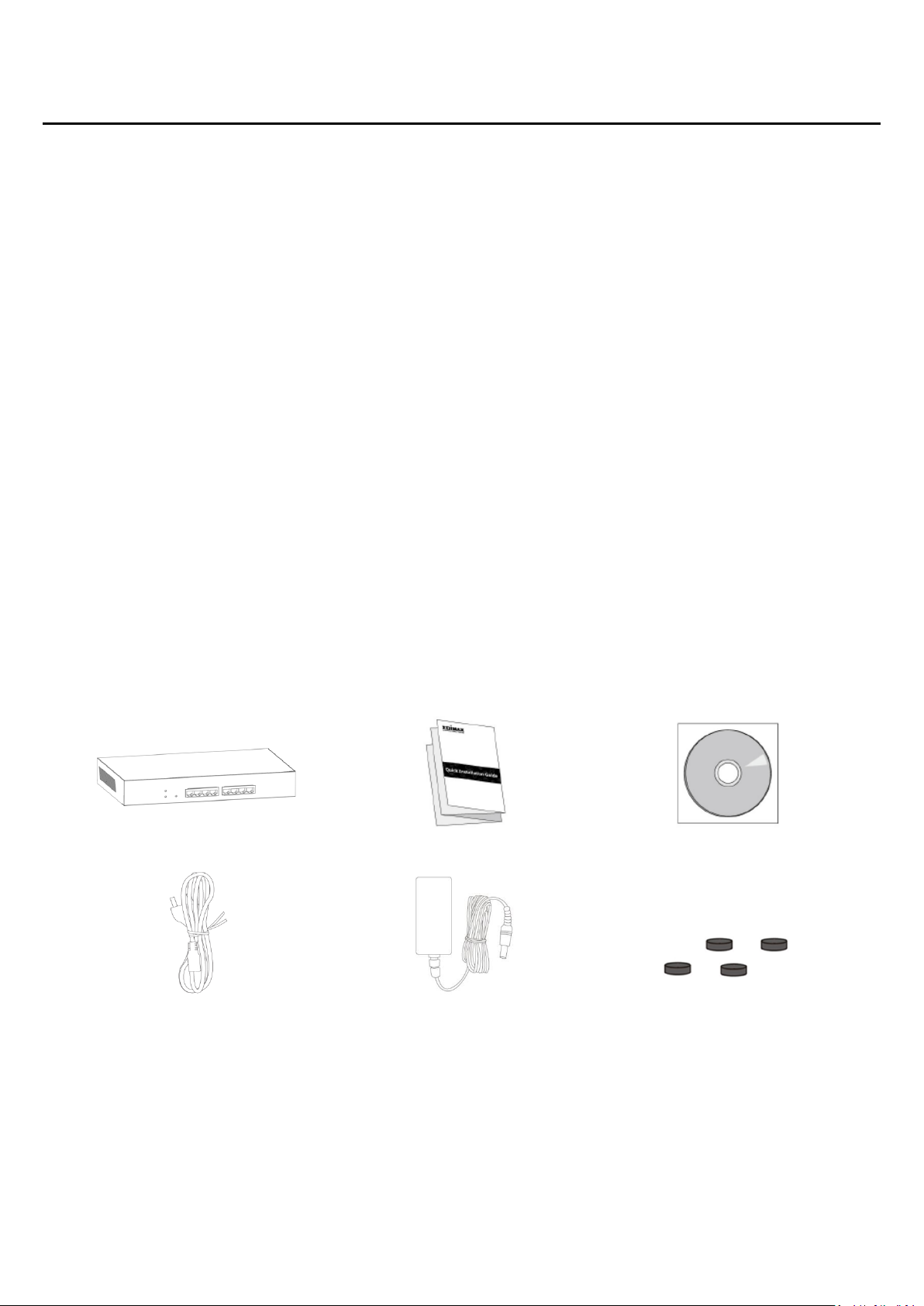
Chapter 2 Introduction
1 2 3
4 5 6
1. GS-3008P Switch
2. Quick Installation Guide
3. CD
4. Power Cord
5. Power Adapter
6. Rubber Feet
Thank you for purchasing an Edimax Gigabit Ethernet PoE+ Web managed switch device. The
Series includes both PoE and non-PoE models powered by Edimax’s Web Smart PoE and Web
Smart interface, respectively.
This document is intended to provide hardware installation instructions as well as an overview
of the interface and management functions of the Web Smart web-based software.
2-1 Overview
The GS-3008P is a PoE+ web managed switch with 8 Gigabit Ethernet ports. The 1-4 port takes
the POE function. The Giga Ethernet Switch provides a seamless network connection with
integrated 1000Mbps Gigabit Ethernet, 100Mbps Fast Ethernet and 10Mbps Ethernet network
capabilities.
2-2 Package contents
Before using the product, check that the items listed below are included and in good condition.
If any item does not accord with the table, please contact your dealer immediately.
5
Page 6

2-3 Features
IEEE 802.3af/at PoE compliant.
Five Gigabit Ethernet ports.
Up to 30W per port (total power budget: 72W) for powering PoE-enabled devices.
Auto-detection of powered devices (PD) and power consumption levels.
Auto fault-detection on over/under current & voltage.
Access Control List (ACL) support.
Switch capacity: 16Gbps & Forwarding rate: 11.9Mpps.
IEEE 802.1Q-based VLAN for network segmentation to improve performance and security.
IEEE 802.1p QoS with 4 priority queues
IGMP Snooping V1 / V2 / V3 support.
4K MAC address table and jumbo frame support up to 9KB.
Small desktop form-factor for small office and home office
6
Page 7
3 1 2 4 5
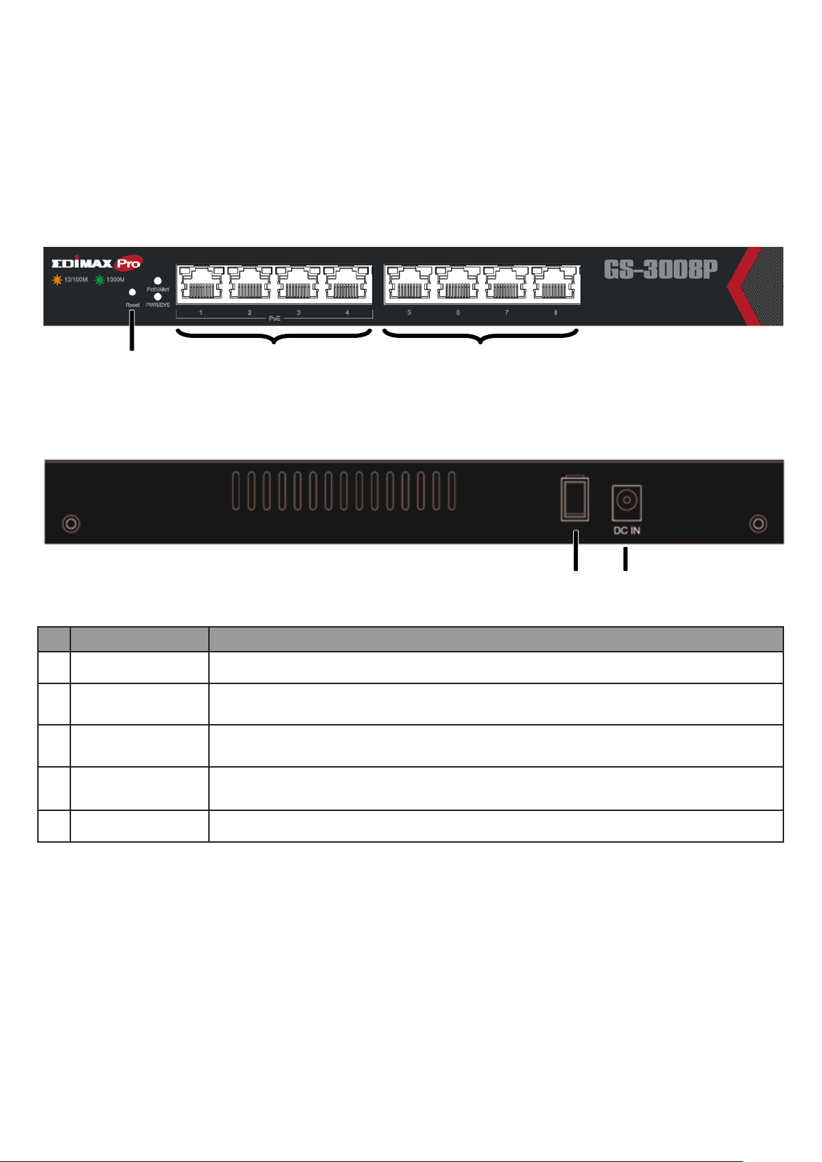
2-4 Product Components
No.
Name
Description
1
Reset button
Press 6 seconds to restore factory default parameters.
2
Ethernet (LAN) PoE
ports (1-4)
PoE ports, compatible with IEEE 802.3af, with 60W dedicated internal power.
3
Ethernet (LAN)
ports (5-8)
Designed to connect to network devices with a bandwidth of 10Mbps, 100Mbps or
1000Mbps. Each has a corresponding 10/100/1000Mbps LED.
4
Power
Off: power off
On: power on
5
DC power in
Supports DC 100 – 240V, 50-60Hz.
2-4-1 Ports
The following view applies to GS-3008P.
Figure 1 GS-3008P Front View
Figure 2 GS-3008P Rear View
7
Page 8

2
3 4
2-4-2 LED Indicators
Name
Description
PWR/SYS
Green LED:
• Off: power off or fail
• On: power on
• Blinking: system boot-up
POE/Alert
Green LED:
• Off: power off or fail
• On: power on
• PoE power output over 50W PoE power budget
Port LED
LINK/ACT LED:
• Off: port disconnected or link fail
• Green on: 1000M connected
• Amber on: 10/100M connected
• Blinking: sending or receiving data
POE LED
POE/ACT LED:
• Off: port disconnected or POE fail
• Green on: POE supply status
The following view applies to GS-3008P.
Figure 3 LED Indicators
8
Page 9

Chapter 3 Installation
This chapter describes how to install and connect your Edimax Switch. Read the following
topics and perform the procedures in the correct order. Incorrect installation may cause
damage to the product.
3-1 Placement Tips
Ambient Temperature – To prevent the switch from overheating, do not operate it in an
area that exceeds an ambient temperature of 122°F (50°C).
Air Flow – Be sure that there is adequate air flow around the switch.
Mechanical Loading – Be sure that the switch is level and stable to avoid any hazardous
conditions.
Circuit Overloading – Adding the switch to the power outlet must not overload that
circuit.
Follow these guidelines to install the switch securely.
1. Put the switch in a stable place such as a desktop, to avoid it falling.
2. Ensure the switch works in the proper AC input range and matches the labeled voltage.
3. Ensure there is proper heat dissipation and adequate ventilation around the switch.
4. Ensure the switch’s location can support the weight of the switch and its accessories.
3-2 Desktop Installation
To place the switch on a desktop:
1. Install the four rubber feet (included) on the bottom of the switch.
2. Place the switch on a flat surface.
Figure 4 Desktop Installation
9
Page 10
Chapter 4 Getting Started
This section provides an introduction to the web-based configuration utility, and covers the
following topics:
Powering on the device
Connecting to the network
Power over Ethernet (PoE) considerations
Starting the web-based configuration utility
4-1 Power
4-1-1 Connecting to Power
The switch is powered by the DC 100-240 V 50/60Hz internal high-performance power supply.
It is recommended to connect the switch with a single-phase three-wire power source with a
neutral outlet, or a multifunctional computer professional source.
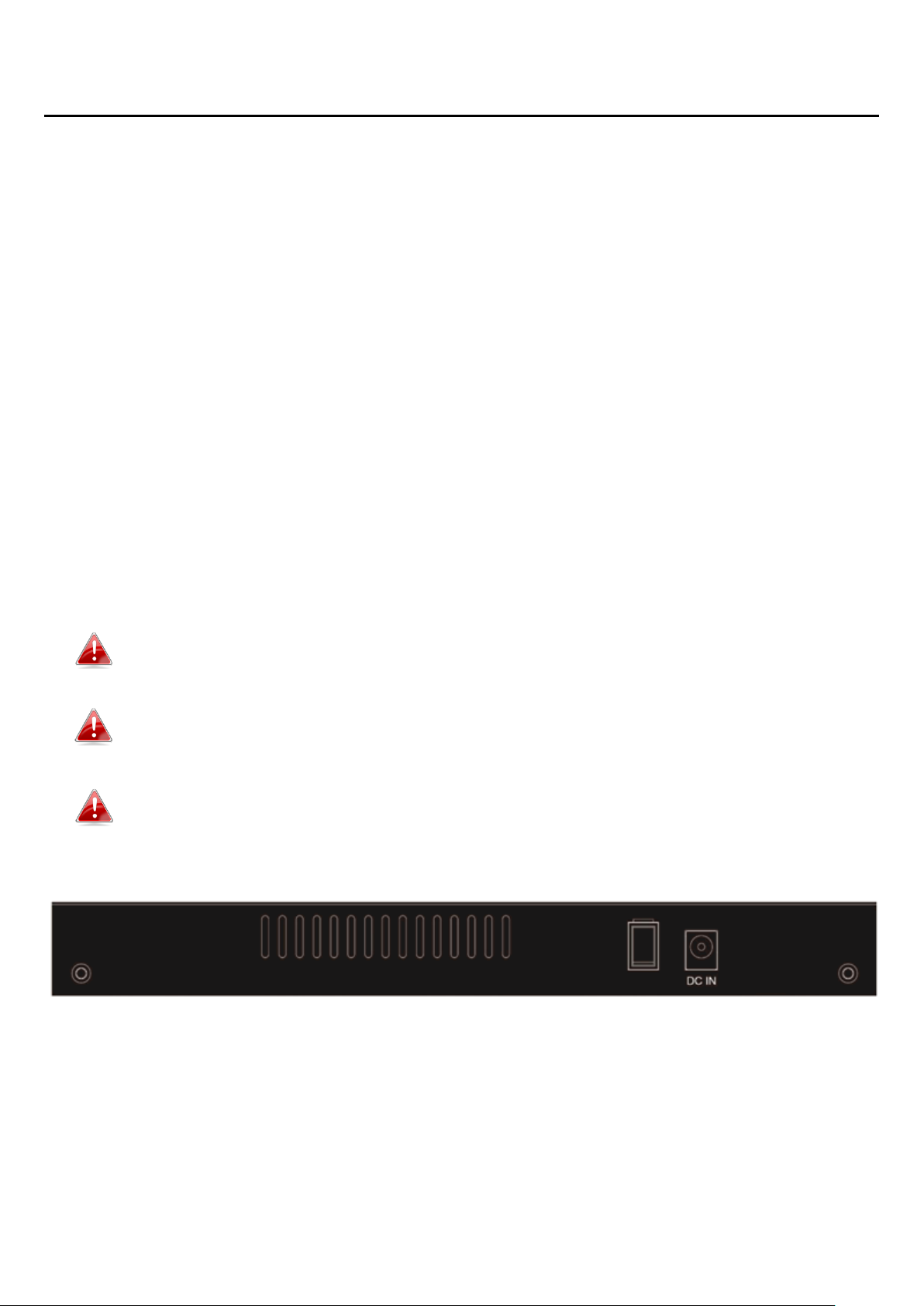
Connect the DC power connector on the back panel of the switch to the external power
source with the included power cord, and check the power LED is on.
Power down and disconnect the power cord before servicing or wiring a switch.
Do not disconnect modules or cabling unless the power is first switched off. The
device only supports the voltage outlined in the type plate. Do not use any other
power components except those specifically designated for the switch.
Disconnect the power cord before installation or cable wiring.
Figure 5 Rear View showing DC Power Socket
10
Page 11
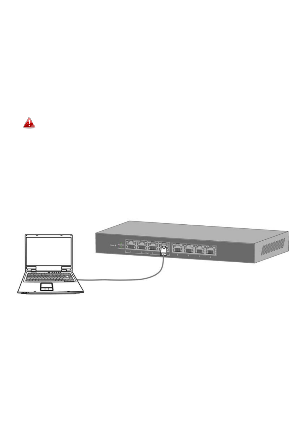
4-1-2 Connecting to the Network
To connect the switch to the network:
1. Connect an Ethernet cable to the Ethernet port of a computer
2. Connect the other end of the Ethernet cable to one of the numbered Ethernet ports of
the switch. The LED of the port will light up to indicate active connection.
3. Repeat Step 1 and Step 2 for the devices to be connected to the switch.
We strongly recommend using CAT-5E or better cable to connect network devices.
When connecting network devices, do not exceed the maximum cabling distance of
100 meters (328 feet). It can take up to one minute for the connected devices or the
LAN to be operational after it is connected. This is normal behavior.
Connect the switch to end nodes using a standard Cat 5/5e Ethernet cable (UTP/STP) as
shown in the illustration below.
Switch ports will automatically adjust to the characteristics (MDI/MDI-X, speed, duplex) of the
device to which the switch is connected.
Figure 6 Connecting PC to Switch
11
Page 12

4-1-3 Power over Ethernet (PoE) Considerations
Model
Power Dedicated to PoE
PoE Ports
PoE Standard Supported
3008P
60W
1 to 4
IEEE802.3at/af
For PoE switch models, consider the following information:
Devices considered a Power Sourcing Equipment (PSE), can support up to 30 Watts per PoE
port on ports 1 to 4 and 30 Watts per PoE port on other ports to a Powered Device (PD).
When connecting switches capable of supplying PoE, consider the following information:
Switch models with PoE function are PSEs. These models are capable of supplying DC
power to attached PDs, such as VoIP phones, IP cameras, and wireless access points (APs).
PoE switches. Additionally, PoE switches are capable of detecting and supplying power to
pre-standard legacy PoE Power Devices. Due to the support for legacy PoE, there is a
possibility that PoE switches acting as a PSE may inadvertently detect and supply power
an attached PSE, including other PoE switches. This false detection may result in a PoE
switch operating improperly and unable to supply power to attached PDs.
The prevention of a false detection can be easily remedied by disabling PoE on the ports
that are used to connect PSEs. Another simple practice to prevent a false detection is to
first power up a PSE device before connecting it to a PoE switch.
When a device is falsely detected as a PD, disconnect the device from the PoE port and
power recycle the device with AC power before reconnecting it to the PoE port.
12
Page 13
4-1-4 Starting the Web-based Configuration Utility
This section describes how to navigate the web-based switch configuration utility.
4-1-5 Browser Restrictions
If you are using older versions of Internet Explorer, you cannot directly use an IPv6
address to access the device. You can, however, use the DNS (Domain Name System)
server to create a domain name that contains the IPv6 address, and then use that domain
name in the address bar in place of the IPv6 address.
If you have multiple IPv6 interfaces on your management station, use the IPv6 global
address instead of the IPv6 link local address to access the device from your browser.
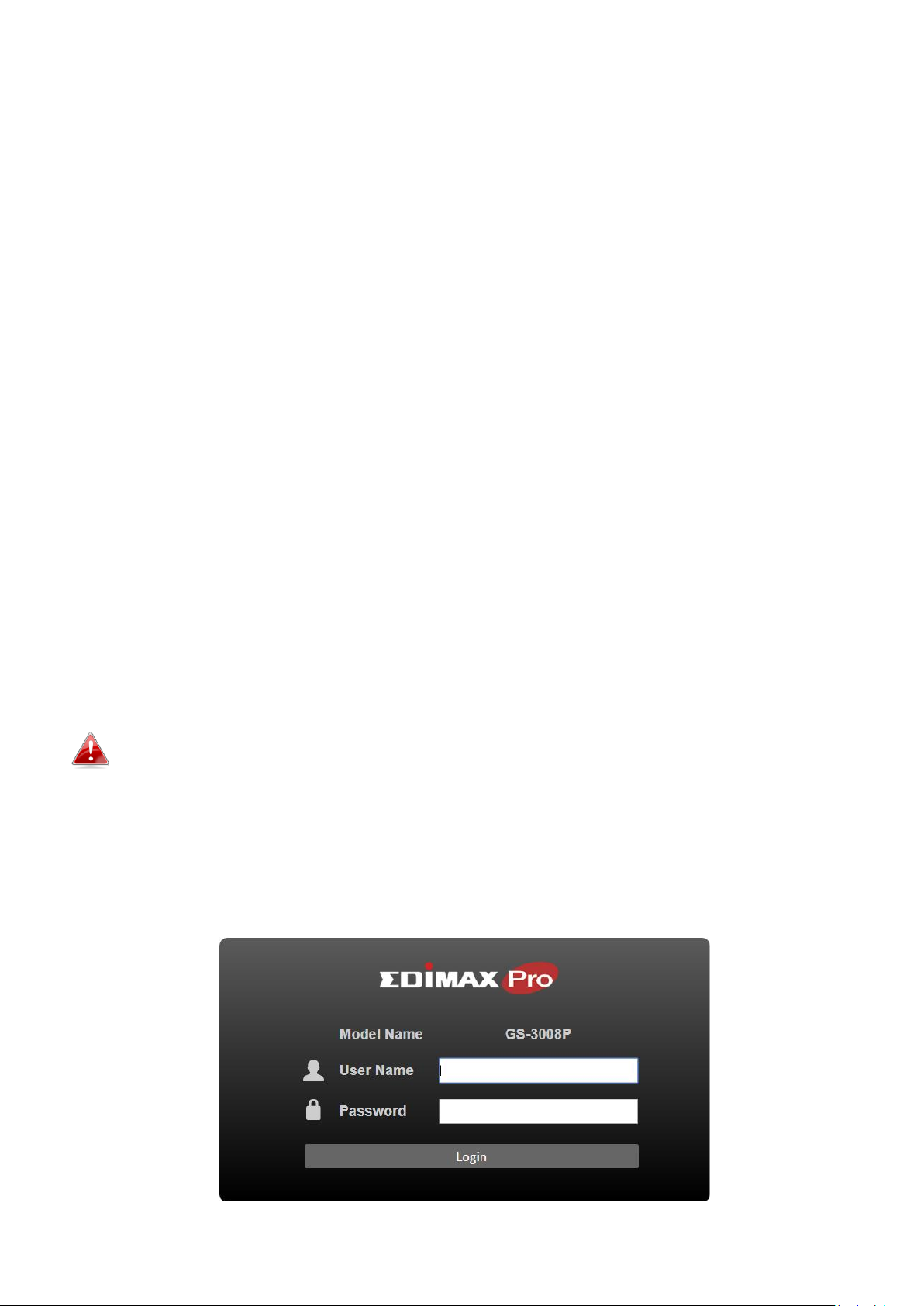
4-1-6 Launching the Configuration Utility
To open the web-based configuration utility:
1. Open a Web browser.
2. Enter the IP address of the device you are configuring in the address bar on the browser
(factory default IP address is 192.168.2.1) and press Enter.
When the device is using the factory default IP address, its power LED will flash
continuously. When the device is using a DHCP assigned IP address or an
administrator-configured static IP address, the power LED will light up a solid color.
Your computer’s IP address must be in the same subnet as the switch. For example,
if the switch is using the factory default IP address, your computer’s IP address can
be in the following range: 192.168.2.x (whereas x is a number from 2 to 254).
After a successful connection, the login window displays.
Figure 7 Login Window
13
Page 14

4-2 Logging In
The default username is admin and the default password is 1234. The first time that you log in
with the default username and password, you are required to enter a new password.
When the login attempt is successful, the System Information Status window displays:
Figure 8 System Information Status
If you entered incorrect username or password, an error message appears and the Login page
remains displayed on the window. If you are having problems logging in, please see the
Launching the Configuration Utility section in the Administration Guide for additional
information.
14
Page 15
Chapter 5 Web-based Switch Configuration
No.
Name
Description
1
Configuration Menu
Navigate to locate specific switch functions.
2
Configuration Settings
Edit specific function settings.
1
2
The PoE Smart-Lite switch software provides rich Layer 2 functionality for switches in your
networks. This chapter describes how to use the web-based management interface (Web UI)
to configure the switch’s features.
For the purposes of this manual, the user interface is separated into two sections, as shown in
the following figure:
Figure 9 User Interface
15
Page 16

5-1 System Information
Item
Description
Model Name
Switch model name.
Device Name
System name of the switch, configurable according to user preference.
Firmware
Version
Current firmware version of the device.
Build Date
Device production date.
MAC Address
A unicast MAC address for which the switch has forwarding and/or filtering information. The
format is a six-byte MAC address, with each byte separated by colons.
IPv4 Address
Switch IPv4 address on the network.
Subnet
Address
A 32-bit number that masks an IP address
Gateway
TCP / IP protocol under the gateway
Loop Status
Displays whether or not loops exist in the network.
PoE Status
Display PoE status
Use this page to view status information such as Device Name, MAC address, IP Address and
loop status.
To view the System Information menu, navigate to System Information.
Figure 10 System Information
16
Page 17

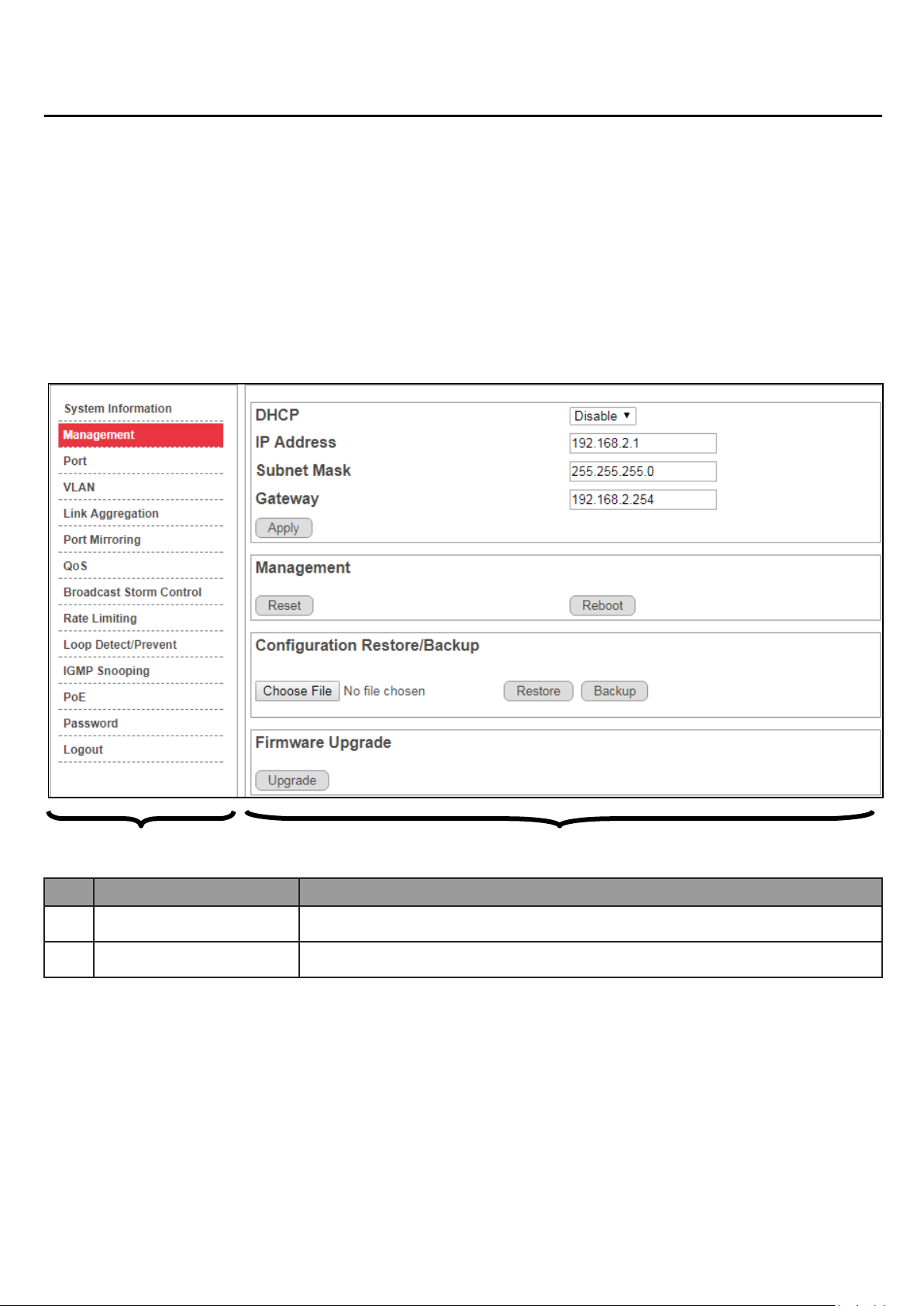
5-2 Management
Item
Description
DHCP
Enable
Obtain an IP address automatically.
Disable
Use a static IP address
Management
Reset
Restore switch to original factory default settings.
Reboot
Reboot switch.
Configuration Restore/Backup
Browse
Click to browse a remote TFTP server or on local storage, to locate a file with a previously
saved switch setting configuration.
Restore
Install selected switch setting configuration file.
Backup
Save current switch setting configuration as a backup file.
Firmware Upgrade
Upgrade
Install selected firmware file.
Use this page to reset the switch to original factory default settings, reboot the switch, backup
and restore switch settings, and upgrade firmware.
To view the Management menu, navigate to Management.
Figure 11 Management
17
Page 18
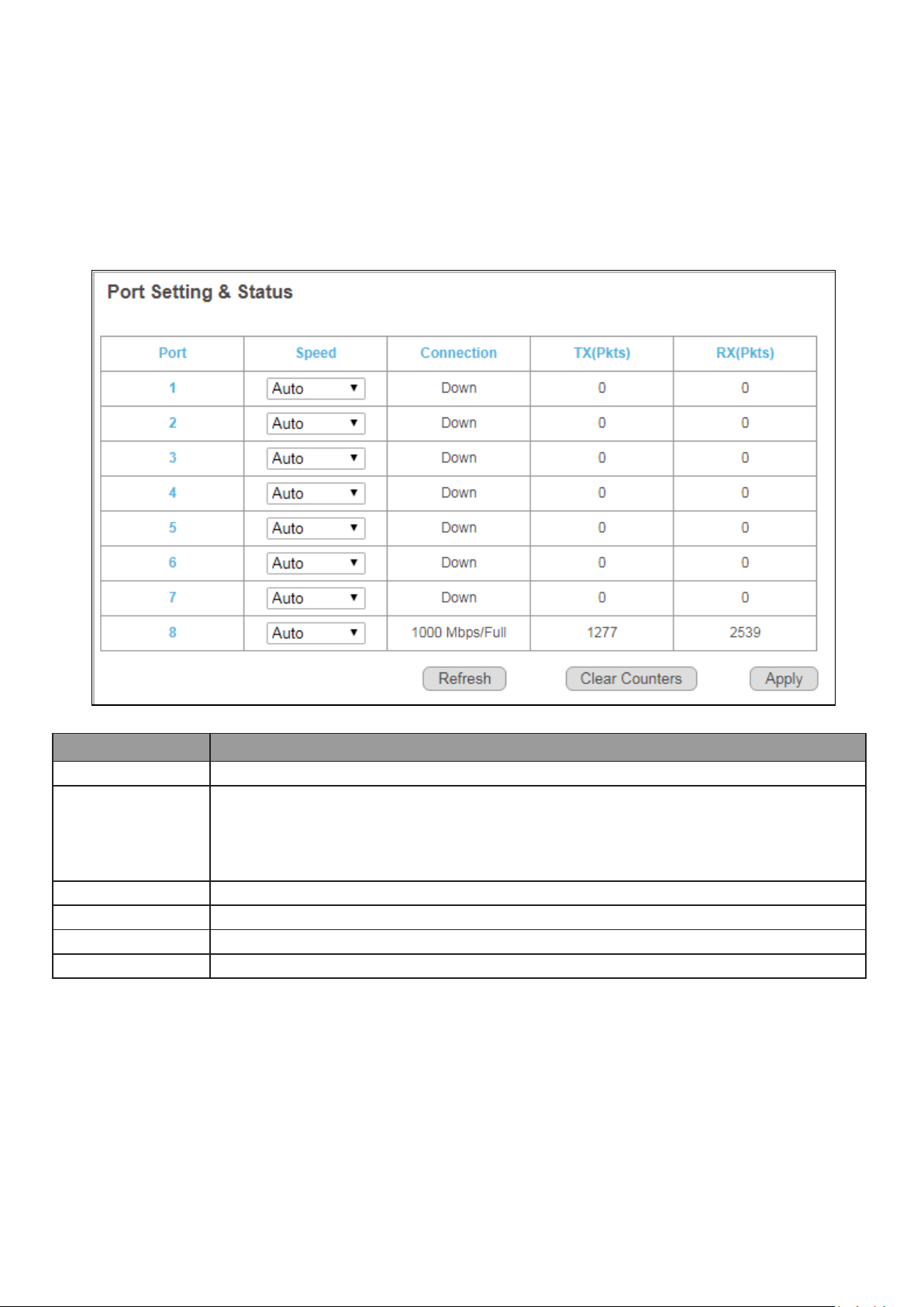
5-3 Port
Item
Description
Port
Designated port number.
Speed
To control the direction and speed of data flow.
Auto
10M Half 100M Half
10M Full 100M Full
Connection
Displays whether or not port is in use, and link speed if it is in use.
TX
The total number of packets transmitted by the port.
RX
The total number of packets received by the port.
Clear Counters
Click to reset tracking data.
Use this page to view traffic information such as Speed, Connection,TX, RX, on each port. The
tracking data on each port can also be reset.
To view the Port menu, navigate to Port.
Figure 12 Port
18
Page 19
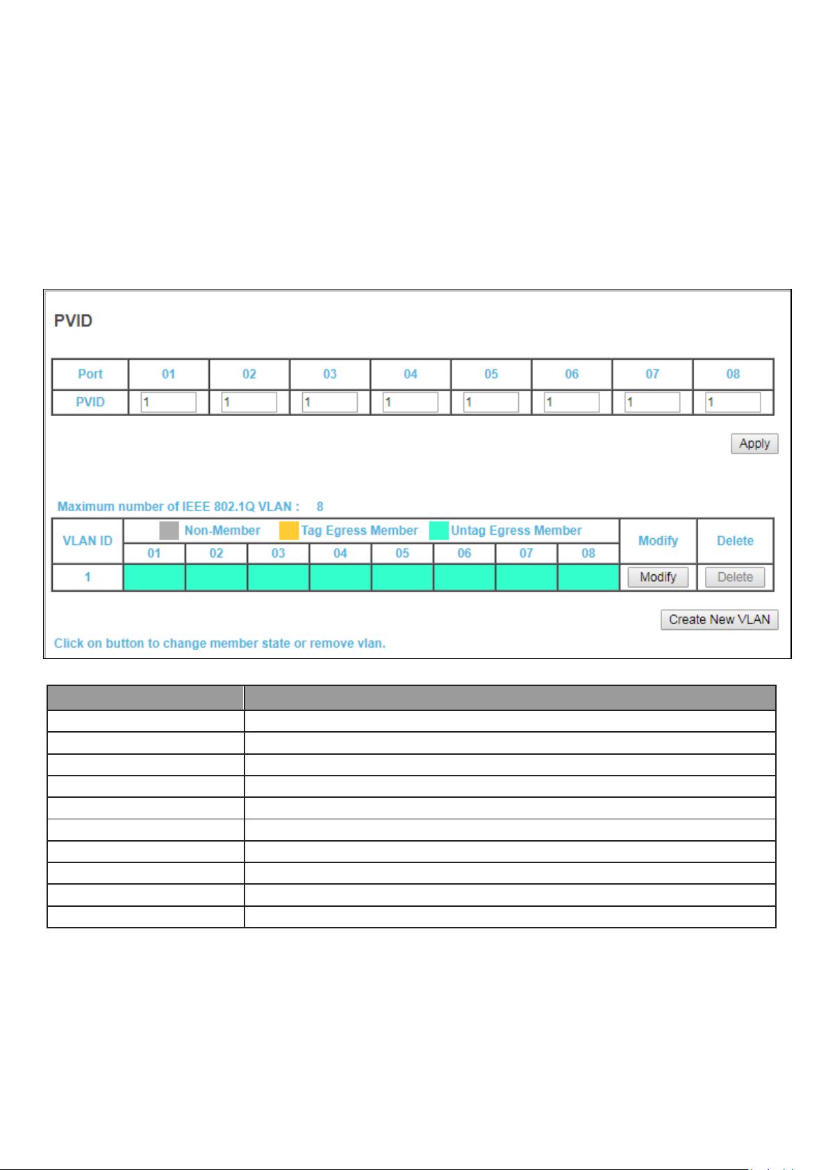
5-4 VLAN
Item
Description
Apply
Click Apply to save the values and update the screen.
Port
Designated port number.
PVID
Enter a VLAN ID for each port.
Create New VLAN
Click Create New VLAN to enter new VLAN settings.
VLAN ID
Virtual LAN ID.
Non-Member
Port is not a member of a VLAN.
Tag Egress Member
Tag outgoing packets of a port which is a member of the VLAN.
Untag Egress Member
Untag outgoing packets of a port which is a member of the VLAN.
Modify
Modify port settings of a specific VLAN.
Delete
Delete a specific VLAN.
Use this section to create and modify VLANs.
5-4-1 IEEE 802.1Q VLAN
To view the IEEE 802.1Q VLAN menu, navigate to VLAN.
Figure 13 VLAN
19
Page 20
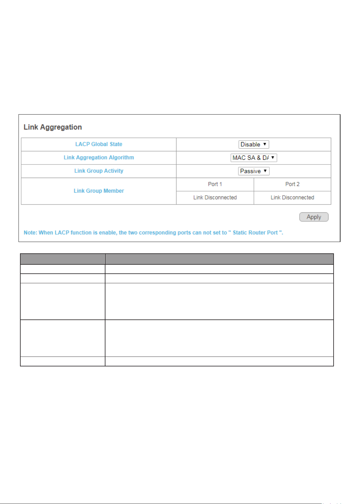
5-5 Link Aggregation
Item
Description
Apply
Click Apply to save the values and update the screen.
LACP Global State
Enable/disable LCAP.
Link Aggregation Algorithm
Select a link aggregation algorithm:
MAC SA & DA
MAC DA
MAC SA
Link Group Activity
Select link group activity status:
Passive
Active
Active
Link Group Members
The ports that are members of a port channel.
Use this option to aggregate multiple Ethernet ports together to form a logical port. This
feature supports static allocation and Link Aggregation Control Protocol .
To view the Link Aggregation menu, navigate to Link Aggregation.
Figure 14 Link Aggregation
20
Page 21

5-6 Port Mirror
Item
Description
Port Mirroring Mode
Disable port mirroring/Select the port mirroring direction.
Disable
Ingress
Egress
Both
Monitor Port
Select the mirror destination port.
Mirrored Port
The ports or configured to mirror traffic to the destination. Multiple source
ports can be configured.
Apply
Click Apply to save the values and update the screen.
Port mirroring selects the network traffic for analysis by a network analyzer. This is done for
specific ports of the switch. As such, many switch ports are configured as source ports and
one switch port is configured as a destination port.
To view the Mirror menu, navigate to Mirror.
Figure 15 Port Mirroring
21
Page 22

5-7 QoS
Item
Description
Disable QoS
Enable/disable QoS.
Port-Based QoS
Click to select port-based QoS settings.
IEEE 802.1p QoS
Click to enter IEEE 802.1Q QoS settings.
Use this section to configure Quality of Service (QoS) settings.
5-7-1 Disable QoS
To view the Disable QoS menu, navigate to QoS > Disable QoS.
Figure 16 QoS > Disable QoS
22
Page 23

5-7-2 Port-Based QoS
Item
Description
Disable QoS
Enable/disable QoS.
Port-Based QoS
Click to select port-based QoS settings.
IEEE 802.1p QoS
Port-Based QoS
Port
Designated port number.
Schedule Method
According to the resource allocation strategy of the system, choose the
allocated algorithm as Strict Priority or WFQ.
Weight
Queue priority value. More packets are sent from a queue with a higher
weight value.
Queue 0-3
Queues used to store traffic until it can be processed or serialized.
To view the Port-Based QoS menu, navigate to QoS > Port-Based QoS
Figure 17 QoS > Port-Based QoS
23
Page 24

To view the Port-Based QoS menu, navigate to QoS > Port-Based QoS
Item
Description
Disable QoS
Enable/disable QoS.
Port-Based QoS
Click to select port-based QoS settings.
IEEE 802.1p QoS
Port-Based QoS.
Port
Designated port number.
Scheduler Method
According to the resource allocation strategy of the system to choose the
allocated algorithm as Strict Priority or WFQ.
Queue 0-3
Queues used to store traffic until it can be processed or serialized.
Figure 18 QoS > Port-Based QoS
24
Page 25

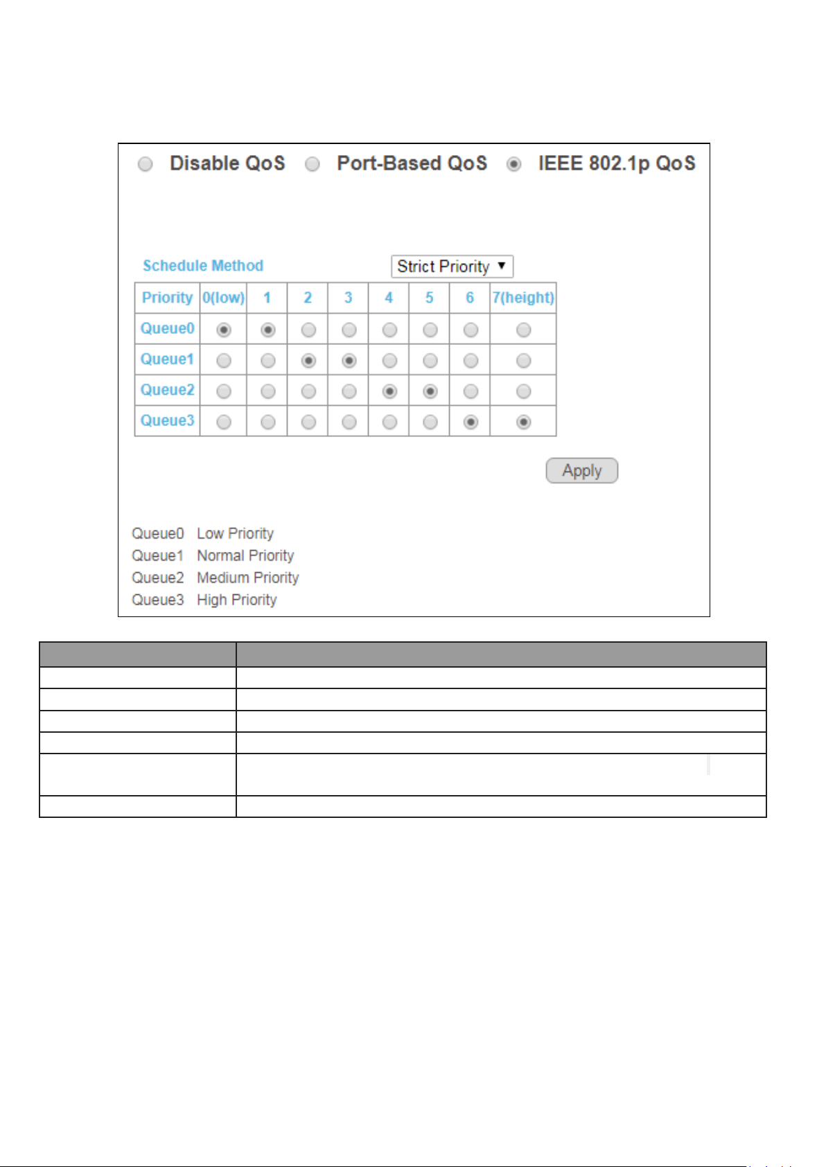
5-7-3 IEEE 802.1p QoS
Item
Description
Disable QoS
Enable/disable QoS.
Port-Based QoS
Click to select port-based QoS settings.
IEEE 802.1p QoS
Click to enter IEEE 802.1Q QoS settings.
Port
Designated port number.
Scheduler Method
According to the resource allocation strategy of the system to choose the
allocated algorithm as Strict Priority or WFQ.
Weight
Queue priority value. More packets are sent from a queue with a higher
weight value.
Queue 0-3
Queues used to store traffic until it can be processed or serialized.
To view the IEEE 802.1p QoS menu, navigate to QoS > IEEE 802.1p QoS.
Figure 19 QoS > IEEE 802.1p QoS
25
Page 26
To view the IEEE 802.1p QoS menu, navigate to QoS > IEEE 802.1p QoS
Item
Description
Disable QoS
Enable/disable QoS.
Port-Based QoS
Click to select port-based QoS settings.
IEEE 802.1p QoS
Click to enter IEEE 802.1Q QoS settings.
Port
Designated port number.
Scheduler Method
According to the resource allocation strategy of the system to choose the
allocated algorithm as Strict Priority or WFQ.
Queue 0-3
Queues used to store traffic until it can be processed or serialized.
Figure 20 QoS > IEEE 802.1p QoS
26
Page 27

5-8 Storm Control
Item
Description
Broadcast
Set Broadcast storm control limit:
• Unlimited
• 512Kbp/s to 512Mbp/s
Multicast
Set Multicast storm control limit:
• Unlimited
• 512Kbp/s to 512Mbp/s
Unicast
Set Unicast storm control limit:
• Unlimited
• 512Kbp/s to 512Mbp/s
Apply
Click Apply to save the values and update the screen.
This page allows you to set ingress port monitoring.
To view the Storm Control menu, navigate to Storm Control.
Figure 21 Storm Control
27
Page 28

5-9 Rate Limiting
Item
Description
Apply
Click Apply to save the values and update the screen.
Port
Designated port number.
Ingress rate
Select to configure the upper limit on how much traffic can enter a port:
• Unlimited
• 512Kbp/s to 512Mbp/s
Egress rate
Select to configure the upper limit on how much traffic can exit a port:
• Unlimited
• 512Kbp/s to 512Mbp/s
This page allows you to display and configure ingress and egress port monitoring settings.
Use this page to configure ingress and egress rate limit settings.
To view the Rate Limiting menu, navigate to Rate Limit.
Figure 22 Rate Limit
28
Page 29
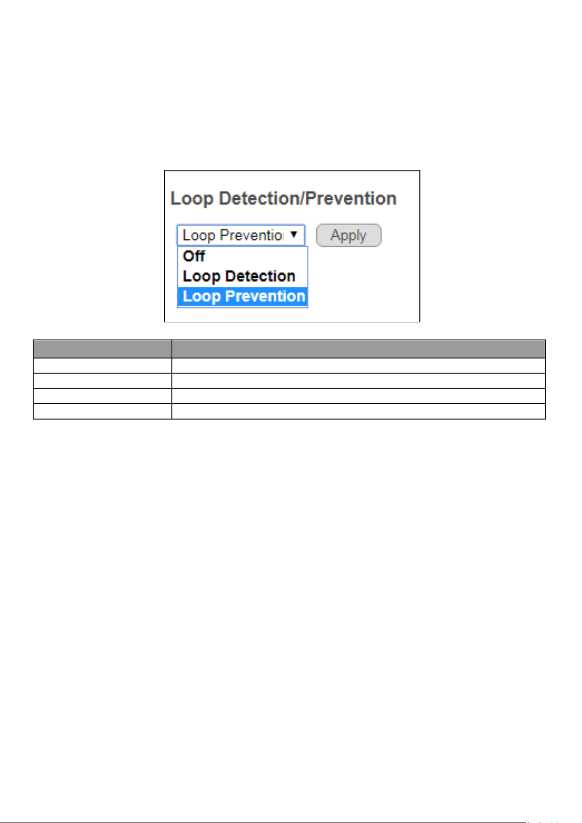
5-10 Loop Detect/Prevent
Item
Description
Off
Disable loop detection and prevention.
Loop Detection
Enable loop detection.
Loop Prevention
Enable loop prevention
Apply
Click Apply to save the values and update the screen.
Use this section to enable/disable and configure network routing loop detection. Select
settings from the drop down menu.
To view the Loop Detection/Prevention menu, navigate to Loop Detection/Prevention.
Figure 23 Network > Loop Detection
29
Page 30
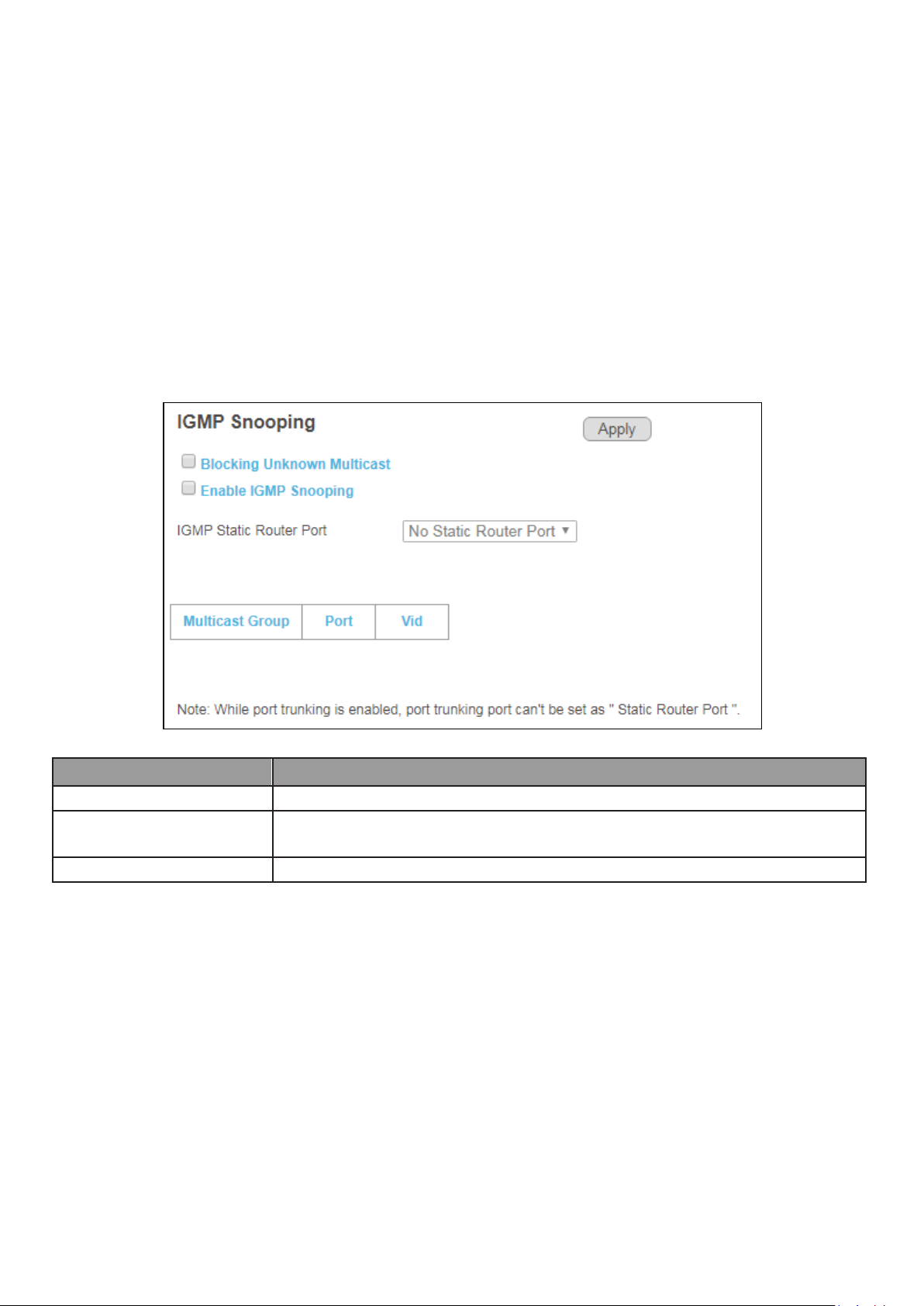
5-11 IGMP Snooping
Item
Description
Enable IGMP Snooping
Enable/disable IGMP snooping.
IGMP Static Router Port
Select a static port on which to snoop, either No Static Router Port, or one of
ports 1-8.
Apply
Click Apply to save the values and update the screen.
Use this section to create an IGMP Snooping Profile. Internet Group Management Protocol
(IGMP) Snooping is a feature that allows a switch to forward multicast traffic intelligently on
the switch. Multicast IP traffic is traffic that is destined to a host group. Host groups are
identified by class D IP addresses, which ranges from 224.0.0.0 to 239.255.255.255. Based on
the IGMP query and report messages, the switch forwards traffic only to the ports that
request the multicast traffic. This prevents the switch from broadcasting the traffic to all ports
and possibly affecting network performance.
To view the IGMP Snooping menu, navigate to IGMP Snooping.
Figure 24 IGMP Snooping
30
Page 31

5-12 PoE
Item
Description
PoE Global Settings
PSE Total Power
Enter values for PSE1 and PSE2, for a total PSE power which must not
exceed 60W.
PoE MAX LED Power
Displays the maximum power supplied to LEDs.
Item
Description
PSE vport voltage
Displays voltage supplied to ports.
PoE Status
Port
Designated port number. Click individual port numbers to enter PoE port
configuration menu for each port.
Power Status
Displays current port power status, on or off.
Real Power (W)
Displays power drawn by the port, in Watts.
Use this section to configure PoE settings for the switch and its ports. PoE Global Settings and
PoE Status
To view the PoE Global Settings and PoE Status menu, navigate to PoE.
Figure 25 PoE Menu
31
Page 32

5-12-1 PoE Port Configuration
Item
Description
Port
Designated port number.
Power Supply
Use the drop down menu to select port power supply options:
Turn on
Turn off
Apply
Click Apply to save the values and update the screen.
To view the PoE Port Configuration menu, navigate to PoE > PoE Status and click on an
individual port number.
Figure 26 PoE > PoE Status > Port Number
32
Page 33
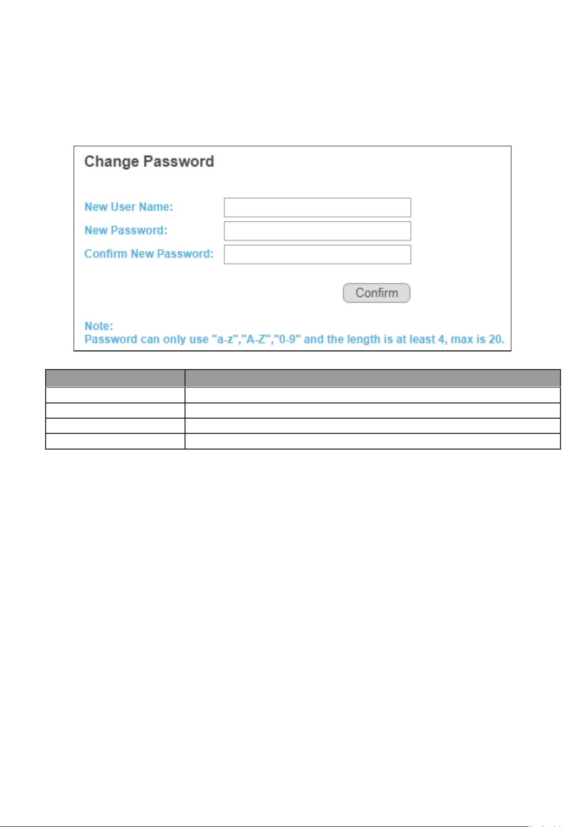
Item
Description
Confirm
Click Confirm to save the values and update the screen.
Old Password
Enter current password.
New Password
Enter new password.
Confirm New Password
Enter new password again to confirm.
5-13 Password
Use these settings to change an account password.
To view the Password menu, navigate to Password.
Figure 27 Password
5-14 Logout
Click Logout to leave the switch management menu and close the web management
session.
By default, the application logs out after five minutes of inactivity.
33
Page 34

COPYRIGHT
Copyright Edimax Technology Co., Ltd. all rights reserved. No part of this publication
may be reproduced, transmitted, transcribed, stored in a retrieval system, or translated
into any language or computer language, in any form or by any means, electronic,
mechanical, magnetic, optical, chemical, manual or otherwise, without the prior written
permission from Edimax Technology Co., Ltd.
Edimax Technology Co., Ltd. makes no representations or warranties, either expressed or
implied, with respect to the contents hereof and specifically disclaims any warranties,
merchantability, or fitness for any particular purpose. Any software described in this
manual is sold or licensed as is. Should the programs prove defective following their
purchase, the buyer (and not this company, its distributor, or its dealer) assumes the
entire cost of all necessary servicing, repair, and any incidental or consequential damages
resulting from any defect in the software. Edimax Technology Co., Ltd. reserves the right
to revise this publication and to make changes from time to time in the contents hereof
without the obligation to notify any person of such revision or changes.
The product you have purchased and the setup screen may appear slightly different from
those shown in this QIG. The software and specifications are subject to change without
notice. Please visit our website www.edimax.com for updates. All brand and product
names mentioned in this manual are trademarks and/or registered trademarks of their
respective holders.
34
Page 35

Federal Communication Commission Interference Statement
This equipment has been tested and found to comply with the limits for a Class B digital device, pursuant to Part
15 of FCC Rules. These limits are designed to provide reasonable protection against harmful interference in a
residential installation. This equipment generates, uses, and can radiate radio frequency energy and, if not
installed and used in accordance with the instructions, may cause harmful interference to radio communications.
However, there is no guarantee that interference will not occur in a particular installation. If this equipment does
cause harmful interference to radio or television reception, which can be determined by turning the equipment
off and on, the user is encouraged to try to correct the interference by one or more of the following measures:
1. Reorient or relocate the receiving antenna.
2. Increase the separation between the equipment and receiver.
3. Connect the equipment into an outlet on a circuit different from that to which the receiver is connected.
4. Consult the dealer or an experienced radio technician for help.
FCC Caution
This device and its antenna must not be co-located or operating in conjunction with any other antenna or
transmitter. This device complies with Part 15 of the FCC Rules. Operation is subject to the following two
conditions: (1) this device may not cause harmful interference, and (2) this device must accept any interference
received, including interference that may cause undesired operation. Any changes or modifications not expressly
approved by the party responsible for compliance could void the authority to operate equipment.
Federal Communications Commission (FCC) Radiation Exposure Statement
This equipment complies with FCC radiation exposure set forth for an uncontrolled environment. In order to avoid
the possibility of exceeding the FCC radio frequency exposure limits, human proximity to the antenna shall not be
less than 2.5cm (1 inch) during normal operation.
Federal Communications Commission (FCC) RF Exposure Requirements
SAR compliance has been established in the laptop computer(s) configurations with PCMCIA slot on the side near
the center, as tested in the application for certification, and can be used in laptop computer(s) with substantially
similar physical dimensions, construction, and electrical and RF characteristics. Use in other devices such as PDAs
or lap pads is not authorized. This transmitter is restricted for use with the specific antenna tested in the
application for certification. The antenna(s) used for this transmitter must not be co-located or operating in
conjunction with any other antenna or transmitter.
R&TTE Compliance Statement
This equipment complies with all the requirements of DIRECTIVE 1999/5/EC OF THE EUROPEAN PARLIAMENT AND
THE COUNCIL of March 9, 1999 on radio equipment and telecommunication terminal equipment and the mutual
recognition of their conformity (R&TTE). The R&TTE Directive repeals and replaces in the directive 98/13/EEC
(Telecommunications Terminal Equipment and Satellite Earth Station Equipment) As of April 8, 2000.
Safety
35
Page 36

This equipment is designed with the utmost care for the safety of those who install and use it. However, special
attention must be paid to the dangers of electric shock and static electricity when working with electrical
equipment. All guidelines of this and of the computer manufacture must therefore be allowed at all times to
ensure the safe use of the equipment.
EU Countries Intended for Use
The ETSI version of this device is intended for home and office use in Austria, Belgium, Bulgaria, Cyprus, Czech,
Denmark, Estonia, Finland, France, Germany, Greece, Hungary, Ireland, Italy, Latvia, Lithuania, Luxembourg, Malta,
Netherlands, Poland, Portugal, Romania, Slovakia, Slovenia, Spain, Sweden, Turkey, and United Kingdom. The ETSI
version of this device is also authorized for use in EFTA member states: Iceland, Liechtenstein, Norway, and
Switzerland.
EU Countries Not Intended for Use
None
36
Page 37

EU Declaration of Conformity
English: This equipment is in compliance with the essential requirements and other relevant
provisions of Directive 1995/5/EC, 2009/125/EC, 2006/95/EC, 2011/65/EC.
Français: Cet équipement est conforme aux exigences essentielles et autres dispositions de la
directive 1995/5/CE, 2009/125/CE, 2006/95/CE, 2011/65/CE.
Čeština: Toto zařízení je v souladu se základními požadavky a ostatními příslušnými ustanoveními
směrnic 1995/5/ES, 2009/125/ES, 2006/95/ES, 2011/65/ES.
Polski: Urządzenie jest zgodne z ogólnymi wymaganiami oraz szczególnymi warunkami
określonymi Dyrektywą UE 1995/5/EC, 2009/125/EC, 2006/95/EC, 2011/65/EC..
Română: Acest echipament este în conformitate cu cerinţele esenţiale şi alte prevederi relevante ale
Directivei 1995/5/CE, 2009/125/CE, 2006/95/CE, 2011/65/CE.
Русский: Это оборудование соответствует основным требованиям и положениям Директивы
1995/5/EC, 2009/125/EC, 2006/95/EC, 2011/65/EC.
Magyar: Ez a berendezés megfelel az alapvető követelményeknek és más vonatkozó irányelveknek
(1995/5/EK, 2009/125/EK, 2006/95/EK, 2011/65/EK).
Türkçe: Bu cihaz 1995/5/EC, 2009/125/EC, 2006/95/EC, 2011/65/EC direktifleri zorunlu istekler ve
diğer hükümlerle ile uyumludur.
Українська: Обладнання відповідає вимогам і умовам директиви 1995/5/EC, 2009/125/EC,
2006/95/EC, 2011/65/EC.
Slovenčina: Toto zariadenie spĺňa základné požiadavky a ďalšie príslušné ustanovenia smerníc
1995/5/ES, 2009/125/ES, 2006/95/ES, 2011/65/ES.
Deutsch: Dieses Gerät erfüllt die Voraussetzungen gemäß den Richtlinien 1995/5/EC, 2009/125/EC,
2006/95/EC, 2011/65/EC.
Español: El presente equipo cumple los requisitos esenciales de la Directiva 1995/5/EC,
2009/125/EC, 2006/95/EC, 2011/65/EC.
Italiano: Questo apparecchio è conforme ai requisiti essenziali e alle altre disposizioni applicabili
della Direttiva 1995/5/CE, 2009/125/CE, 2006/95/CE, 2011/65/CE.
Nederlands: Dit apparaat voldoet aan de essentiële eisen en andere van toepassing zijnde bepalingen
van richtlijn 1995/5/EC, 2009/125/EC, 2006/95/EC, 2011/65/EC..
Português: Este equipamento cumpre os requesitos essênciais da Directiva 1995/5/EC, 2009/125/EC,
2006/95/EC, 2011/65/EC.
Norsk: Dette utstyret er i samsvar med de viktigste kravene og andre relevante regler i Direktiv
1995/5/EC, 2009/125/EC, 2006/95/EC, 2011/65/EC.
Svenska: Denna utrustning är i överensstämmelse med de väsentliga kraven och övriga relevanta
bestämmelser i direktiv 1995/5/EG, 2009/125/EG, 2006/95/EG, 2011/65/EG.
Dansk: Dette udstyr er i overensstemmelse med de væ sentligste krav og andre relevante
forordninger i direktiv 1995/5/EC, 2009/125/EC, 2006/95/EC, 2011/65/EC.
suomen kieli: Tämä laite täyttää direktiivien 1995/5/EY, 2009/125/EY, 2006/95/EY, 2011/65/EY
oleelliset vaatimukset ja muut asiaankuuluvat määräykset.
-----------------------------------------------------------------------------------------------
WEEE Directive & Product Disposal
At the end of its serviceable life, this product should not be treated as household or general waste. It
should be handed over to the applicable collection point for the recycling of electrical and electronic
equipment, or returned to the supplier for disposal.
37
Page 38

Declaration of Conformity
We, Edimax Technology Co., Ltd., declare under our sole responsibility, that the
equipment described below complies with the requirements of the European R&TTE
directives.
Equipment:
GS-3008P PoE+ Web Smart Switch
Model No.:
GS-3008P
The following European standards for essential requirements have been followed:
Directives 2014/30/EU
EMC
:
EN55032:2015
EN55024:2010
EN61000-3-2:2014 class A
EN61000-3-3:2013
Safety (LVD)
:
EN 60950-1:2006 + A11:2009 + A1:2010 + A12:2011+A2:2013
Edimax Technology Co., Ltd.
No. 278, Xinhu 1st Rd., Neihu Dist.,
Taipei City, Taiwan
Date of Signature:
Nov, 2017
Signature:
Printed Name:
Albert Chang
Title:
Director
Edimax Technology Co., Ltd.
38
Page 39

Notice According to GNU General Public License Version 2
This product includes software that is subject to the GNU General Public License version 2. The program is free software and
distributed without any warranty of the author. We offer, valid for at least three years, to give you, for a charge no more
than the costs of physically performing source distribution, a complete machine-readable copy of the corresponding source
code.
Das Produkt beinhaltet Software, die den Bedingungen der GNU/GPL-Version 2 unterliegt. Das Programm ist eine sog. „Free
Software“, der Autor stellt das Programm ohne irgendeine Gewährleistungen zur Verfügung. Wir bieten Ihnen für einen
Zeitraum von drei Jahren an, eine vollständige maschinenlesbare Kopie des Quelltextes der Programme zur Verfügung zu
stellen – zu nicht höheren Kosten als denen, die durch den physikalischen Kopiervorgang anfallen.
GNU GENERAL PUBLIC LICENSE
Version 2, June 1991
Copyright (C) 1989, 1991 Free Software Foundation, Inc. 51 Franklin Street, Fifth Floor, Boston, MA 02110-1301, USA
Everyone is permitted to copy and distribute verbatim copies of this license document, but changing it is not allowed.
Preamble
The licenses for most software are designed to take away your freedom to share and change it. By contrast, the GNU General
Public License is intended to guarantee your freedom to share and change free software--to make sure the software is free
for all its users. This General Public License applies to most of the Free Software Foundation’s software and to any other
program whose authors commit to using it. (Some other Free Software Foundation software is covered by the GNU Lesser
General Public License instead.) You can apply it to your programs, too.
When we speak of free software, we are referring to freedom, not price. Our General Public Licenses are designed to make
sure that you have the freedom to distribute copies of free software (and charge for this service if you wish), that you receive
source code or can get it if you want it, that you can change the software or use pieces of it in new free programs; and that
you know you can do these things.
To protect your rights, we need to make restrictions that forbid anyone to deny you these rights or to ask you to surrender
the rights. These restrictions translate to certain responsibilities for you if you distribute copies of the software, or if you
modify it.
For example, if you distribute copies of such a program, whether gratis or for a fee, you must give the recipients all the rights
that you have. You must make sure that they, too, receive or can get the source code. And you must show them these terms
so they know their rights.
39
Page 40

We protect your rights with two steps: (1) copyright the software, and (2) offer you this license which gives you legal
permission to copy, distribute and/or modify the software.
Also, for each author’s protection and ours, we want to make certain that everyone understands that there is no warranty for
this free software. If the software is modified by someone else and passed on, we want its recipients to know that what they
have is not the original, so that any problems introduced by others will not reflect on the original authors’ reputations.
Finally, any free program is threatened constantly by software patents. We wish to avoid the danger that redistributors of a
free program will individually obtain patent licenses, in effect making the program proprietary. To prevent this, we have
made it clear that any patent must be licensed for everyone’s free use or not licensed at all.
The precise terms and conditions for copying, distribution and modification follow.
TERMS AND CONDITIONS FOR COPYING, DISTRIBUTION AND MODIFICATION
0. This License applies to any program or other work which contains a notice placed by the copyright holder saying it may be
distributed under the terms of this General Public License. The ‘“Program’“, below, refers to any such program or work, and a
‘“work based on the Program’“ means either the Program or any derivative work under copyright law: that is to say, a work
containing the Program or a portion of it, either verbatim or with modifications and/or translated into another language.
(Hereinafter, translation is included without limitation in the term ‘“modification’“.) Each licensee is addressed as ‘“you’“.
Activities other than copying, distribution and modification are not covered by this License; they are outside its scope. The
act of running the Program is not restricted, and the output from the Program is covered only if its contents constitute a
work based on the Program (independent of having been made by running the Program). Whether that is true depends on
what the Program does.
1. You may copy and distribute verbatim copies of the Program’s source code as you receive it, in any medium, provided that
you conspicuously and appropriately publish on each copy an appropriate copyright notice and disclaimer of warranty; keep
intact all the notices that refer to this License and to the absence of any warranty; and give any other recipients of the
Program a copy of this License along with the Program.
You may charge a fee for the physical act of transferring a copy, and you may at your option offer warranty protection in
exchange for a fee.
2. You may modify your copy or copies of the Program or any portion of it, thus forming a work based on the Program, and
copy and distribute such modifications or work under the terms of Section 1 above, provided that you also meet all of these
conditions:
a) You must cause the modified files to carry prominent notices stating that you changed the files and the date of any
change.
40
Page 41

b) You must cause any work that you distribute or publish, that in whole or in part contains or is derived from the
Program or any part thereof, to be licensed as a whole at no charge to all third parties under the terms of this
License.
c) If the modified program normally reads commands interactively when run, you must cause it, when started
running for such interactive use in the most ordinary way, to print or display an announcement including an
appropriate copyright notice and a notice that there is no warranty (or else, saying that you provide a warranty)
and that users may redistribute the program under these conditions, and telling the user how to view a copy of
this License. (Exception: if the Program itself is interactive but does not normally print such an announcement,
your work based on the Program is not required to print an announcement.)
These requirements apply to the modified work as a whole. If identifiable sections of that work are not derived from the
Program, and can be reasonably considered independent and separate works in themselves, then this License, and its terms,
do not apply to those sections when you distribute them as separate works. But when you distribute the same sections as
part of a whole which is a work based on the Program, the distribution of the whole must be on the terms of this License,
whose permissions for other licensees extend to the entire whole, and thus to each and every part regardless of who wrote
it.
Thus, it is not the intent of this section to claim rights or contest your rights to work written entirely by you; rather, the intent
is to exercise the right to control the distribution of derivative or collective works based on the Program.
In addition, mere aggregation of another work not based on the Program with the Program (or with a work based on the
Program) on a volume of a storage or distribution medium does not bring the other work under the scope of this License.
3. You may copy and distribute the Program (or a work based on it, under Section 2) in object code or executable form under
the terms of Sections 1 and 2 above provided that you also do one of the following:
a) Accompany it with the complete corresponding machine-readable source code, which must be distributed under
the terms of Sections 1 and 2 above on a medium customarily used for software interchange; or,
b) Accompany it with a written offer, valid for at least three years, to give any third party, for a charge no more than
your cost of physically performing source distribution, a complete machine-readable copy of the corresponding
source code, to be distributed under the terms of Sections 1 and 2 above on a medium customarily used for
software interchange; or,
c) Accompany it with the information you received as to the offer to distribute corresponding source code. (This
alternative is allowed only for noncommercial distribution and only if you received the program in object code or
executable form with such an offer, in accord with Subsection b above.)
The source code for a work means the preferred form of the work for making modifications to it. For an executable work,
complete source code means all the source code for all modules it contains, plus any associated interface definition files, plus
the scripts used to control compilation and installation of the executable. However, as a special exception, the source code
distributed need not include anything that is normally distributed (in either source or binary form) with the major
components (compiler, kernel, and so on) of the operating system on which the executable runs, unless that component
itself accompanies the executable.
41
Page 42

If distribution of executable or object code is made by offering access to copy from a designated place, then offering
equivalent access to copy the source code from the same place counts as distribution of the source code, even though third
parties are not compelled to copy the source along with the object code.
4. You may not copy, modify, sublicense, or distribute the Program except as expressly provided under this License. Any
attempt otherwise to copy, modify, sublicense or distribute the Program is void, and will automatically terminate your rights
under this License. However, parties who have received copies, or rights, from you under this License will not have their
licenses terminated so long as such parties remain in full compliance.
5. You are not required to accept this License, since you have not signed it. However, nothing else grants you permission to
modify or distribute the Program or its derivative works. These actions are prohibited by law if you do not accept this License.
Therefore, by modifying or distributing the Program (or any work based on the Program), you indicate your acceptance of
this License to do so, and all its terms and conditions for copying, distributing or modifying the Program or works based on it.
6. Each time you redistribute the Program (or any work based on the Program), the recipient automatically receives a license
from the original licensor to copy, distribute or modify the Program subject to these terms and conditions. You may not
impose any further restrictions on the recipients’ exercise of the rights granted herein. You are not responsible for enforcing
compliance by third parties to this License.
7. If, as a consequence of a court judgment or allegation of patent infringement or for any other reason (not limited to patent
issues), conditions are imposed on you (whether by court order, agreement or otherwise) that contradict the conditions of
this License, they do not excuse you from the conditions of this License. If you cannot distribute so as to satisfy
simultaneously your obligations under this License and any other pertinent obligations, then as a consequence you may not
distribute the Program at all. For example, if a patent license would not permit royalty-free redistribution of the Program by
all those who receive copies directly or indirectly through you, then the only way you could satisfy both it and this License
would be to refrain entirely from distribution of the Program.
If any portion of this section is held invalid or unenforceable under any particular circumstance, the balance of the section is
intended to apply and the section as a whole is intended to apply in other circumstances.
It is not the purpose of this section to induce you to infringe any patents or other property right claims or to contest validity
of any such claims; this section has the sole purpose of protecting the integrity of the free software distribution system,
which is implemented by public license practices. Many people have made generous contributions to the wide range of
software distributed through that system in reliance on consistent application of that system; it is up to the author/donor to
decide if he or she is willing to distribute software through any other system and a licensee cannot impose that choice.
This section is intended to make thoroughly clear what is believed to be a consequence of the rest of this License.
8. If the distribution and/or use of the Program is restricted in certain countries either by patents or by copyrighted interfaces,
the original copyright holder who places the Program under this License may add an explicit geographical distribution
42
Page 43

limitation excluding those countries, so that distribution is permitted only in or among countries not thus excluded. In such
case, this License incorporates the limitation as if written in the body of this License.
9. The Free Software Foundation may publish revised and/or new versions of the General Public License from time to time.
Such new versions will be similar in spirit to the present version, but may differ in detail to address new problems or
concerns.
Each version is given a distinguishing version number. If the Program specifies a version number of this License which applies
to it and ‘“any later version’“, you have the option of following the terms and conditions either of that version or of any later
version published by the Free Software Foundation. If the Program does not specify a version number of this License, you
may choose any version ever published by the Free Software Foundation.
10. If you wish to incorporate parts of the Program into other free programs whose distribution conditions are different,
write to the author to ask for permission. For software which is copyrighted by the Free Software Foundation, write to the
Free Software Foundation; we sometimes make exceptions for this. Our decision will be guided by the two goals of
preserving the free status of all derivatives of our free software and of promoting the sharing and reuse of software
generally.
NO WARRANTY
11. BECAUSE THE PROGRAM IS LICENSED FREE OF CHARGE, THERE IS NO WARRANTY FOR THE PROGRAM, TO THE EXTENT
PERMITTED BY APPLICABLE LAW. EXCEPT WHEN OTHERWISE STATED IN WRITING THE COPYRIGHT HOLDERS AND/OR OTHER
PARTIES PROVIDE THE PROGRAM ‘“AS IS’“ WITHOUT WARRANTY OF ANY KIND, EITHER EXPRESSED OR IMPLIED, INCLUDING,
BUT NOT LIMITED TO, THE IMPLIED WARRANTIES OF MERCHANTABILITY AND FITNESS FOR A PARTICULAR PURPOSE. THE
ENTIRE RISK AS TO THE QUALITY AND PERFORMANCE OF THE PROGRAM IS WITH YOU. SHOULD THE PROGRAM PROVE
DEFECTIVE, YOU ASSUME THE COST OF ALL NECESSARY SERVICING, REPAIR OR CORRECTION.
12. IN NO EVENT UNLESS REQUIRED BY APPLICABLE LAW OR AGREED TO IN WRITING WILL ANY COPYRIGHT HOLDER, OR ANY
OTHER PARTY WHO MAY MODIFY AND/OR REDISTRIBUTE THE PROGRAM AS PERMITTED ABOVE, BE LIABLE TO YOU FOR
DAMAGES, INCLUDING ANY GENERAL, SPECIAL, INCIDENTAL OR CONSEQUENTIAL DAMAGES ARISING OUT OF THE USE OR
INABILITY TO USE THE PROGRAM (INCLUDING BUT NOT LIMITED TO LOSS OF DATA OR DATA BEING RENDERED INACCURATE
OR LOSSES SUSTAINED BY YOU OR THIRD PARTIES OR A FAILURE OF THE PROGRAM TO OPERATE WITH ANY OTHER
PROGRAMS), EVEN IF SUCH HOLDER OR OTHER PARTY HAS BEEN ADVISED OF THE POSSIBILITY OF SUCH DAMAGES.
43
 Loading...