

Page 1

User Manual
08-2018 / v1.0
ES-5424P
Edim
Page 2

CONTENTS
I Introduction ................................................................................................................ 1
I-1 Overview ........................................................................................................ 1
I-2 Package Content ............................................................................................ 1
I-3 Features ......................................................................................................... 2
I-4 Product Components ..................................................................................... 2
I-4-1 Ports .............................................................................................................. 2
I-4-2 LED Indicators ................................................................................................ 3
II Installation .................................................................................................................. 4
II-1 Mounting the Switch ...................................................................................... 4
II-1-1 Placement Tips ............................................................................................... 4
II-1-2 Rack Mounting ............................................................................................... 5
III Getting Started ............................................................................................................ 7
III-1 Power ............................................................................................................. 7
III-1-1 Connecting to Power ...................................................................................... 7
III-1-2 Connecting to Network .................................................................................. 8
III-1-3 Power over Ethernet (PoE) Considerations .................................................... 9
III-1-4 Starting the Web-based Configuration Utility .............................................. 10
III-1-5 Logging In ..................................................................................................... 11
III-1-6 Logging Out .................................................................................................. 12
IV Web-based Switch Configuration .............................................................................. 13
IV-1 Administrator ............................................................................................... 14
IV-1-1 System Information...................................................................................... 14
IV-1-2 Account/ Password ...................................................................................... 15
IV-1-3 IP Configuration ........................................................................................... 16
IV-1-3-1 IPv4 .............................................................................................................. 16
IV-1-3-2 IPv6 .............................................................................................................. 17
IV-1-4 SNMP Settings .............................................................................................. 17
IV-1-4-1 SNMP View Table ......................................................................................... 18
IV-1-4-2 SNMP Group Table ....................................................................................... 19
Page 3

IV-1-4-3 SNMP User Table ......................................................................................... 20
IV-1-4-4 SNMP Community Table .............................................................................. 20
IV-1-4-5 SNMP Host Table ......................................................................................... 21
IV-1-4-6 SNMP Configuration ..................................................................................... 22
IV-1-5 NTP Settings ................................................................................................. 23
IV-1-6 Syslog Settings ............................................................................................. 24
IV-1-7 Load Factory Default .................................................................................... 25
IV-1-8 Configuration ............................................................................................... 26
IV-1-8-1 Backup ......................................................................................................... 26
IV-1-8-2 Restore ........................................................................................................ 26
IV-1-9 Firmware Update ......................................................................................... 27
IV-2 Port Management ........................................................................................ 27
IV-2-1 Port Configuration ....................................................................................... 27
IV-2-2 Port Mirror Function .................................................................................... 29
IV-2-3 Broadcast Storm Protection ......................................................................... 30
IV-2-4 Bandwidth Control ....................................................................................... 32
IV-3 VLAN Configuration ...................................................................................... 33
IV-3-1 VLAN Mode .................................................................................................. 33
IV-3-2 VLAN Group-based Entry Config .................................................................. 34
IV-3-3 VLAN Tag-based Entry Config ....................................................................... 35
IV-3-4 VLAN Port Config.......................................................................................... 37
IV-3-5 Protocol VLAN Config ................................................................................... 39
IV-3-6 QinQ Port Config .......................................................................................... 40
IV-3-7 QinQ Index Config ........................................................................................ 41
IV-4 QoS(Quality of Service) Configuration .......................................................... 42
IV-4-1 QoS Group Member ..................................................................................... 42
IV-4-2 QoS Mode Set .............................................................................................. 43
IV-4-3 QoS Out Queue Aging .................................................................................. 45
IV-4-4 QoS Remap .................................................................................................. 46
IV-4-5 Class of Service............................................................................................. 47
Page 4

IV-4-6 802.1q Base ................................................................................................. 48
IV-4-7 DSCP Base .................................................................................................... 49
IV-4-8 TCP/UDP Port Base ...................................................................................... 50
IV-5 ACL Configuration ........................................................................................ 51
IV-5-1 ACL Profile List ............................................................................................. 51
IV-5-2 ACL Ctag Settings ......................................................................................... 57
IV-6 Security ........................................................................................................ 59
IV-6-1 Port-MAC-IP Binding .................................................................................... 59
IV-6-1-1 Port-MAC-IP Port Settings ............................................................................ 59
IV-6-1-2 Port-MAC-IP Entry Setting ............................................................................ 61
IV-6-1-3 DHCP Snooping Entry Setting ....................................................................... 62
IV-6-2 MAC Address Binding ................................................................................... 62
IV-7 Advanced Features ...................................................................................... 65
IV-7-1 Spanning Tree Protocol STP ......................................................................... 65
IV-7-1-1 STP Global Settings ...................................................................................... 65
IV-7-1-2 STP Port Settings .......................................................................................... 67
IV-7-1-3 MST Configuration Identification ................................................................. 67
IV-7-1-4 STP Instance Settings ................................................................................... 69
IV-7-1-5 MSTP Port Information ................................................................................ 69
IV-7-2 Trunk & Link Aggregation ............................................................................. 70
IV-7-3 IGMP Snooping ............................................................................................ 71
IV-7-3-1 IGMP Snooping Settings ............................................................................... 71
IV-7-3-2 IGMP Snooping Router Ports Settings .......................................................... 72
IV-7-3-3 IGMP Snooping Groups ................................................................................ 73
IV-7-3-4 IGMP Snooping Ports ................................................................................... 73
IV-7-4 MLD Snooping .............................................................................................. 74
IV-7-4-1 MLD Snooping Settings ................................................................................ 74
IV-7-4-2 MLD Snooping Router Ports Settings ........................................................... 75
IV-7-4-3 MLD Snooping Groups ................................................................................. 75
IV-7-4-4 MLD Snooping Ports ..................................................................................... 76
Page 5

IV-7-4-5 DHCP Relay Agent ........................................................................................ 77
IV-7-5 Loop Detect.................................................................................................. 78
IV-7-6 GVRP ............................................................................................................ 79
IV-7-7 Neighbor MACID .......................................................................................... 80
IV-8 Monitoring ................................................................................................... 81
IV-8-1 MIB Counter ................................................................................................. 81
IV-8-2 Scan MACID Lookup Table ........................................................................... 83
IV-8-3 Syslog ........................................................................................................... 84
Page 6

Safety and Regulatory
Audience
This guide is for the networking professional managing the standalone PG28CB switch series. It is recommended that only
professionals with experience working with Intelligent Technology INC. networking devices who are familiar with the
Ethernet and local area networking terminology, should service the equipment.
Conventions
The following conventions are used in this manual to convey instructions and information:
Command descriptions use these conventions:
• Commands and keywords are in boldface text.
• Arguments for which you supply values are in italic.
• Square brackets ([ ]) mean optional elements.
• Braces ({ }) group required choices, and vertical bars ( | ) separate the alternative elements.
• Braces and vertical bars within square brackets ([{ | }]) mean a required choice within an optional
element.
Interactive examples use these conventions:
• Nonprinting characters, such as passwords or tabs, are in angle brackets (< >). Notes and cautions
use the following conventions and symbols:
Note
Means additional information. Notes contain additional useful information or references to material available
outside of this document.
Caution
Indicates that the reader must be careful. In a situation where a Caution is listed, a user may cause equipment
damage or loss of data.
Page 7
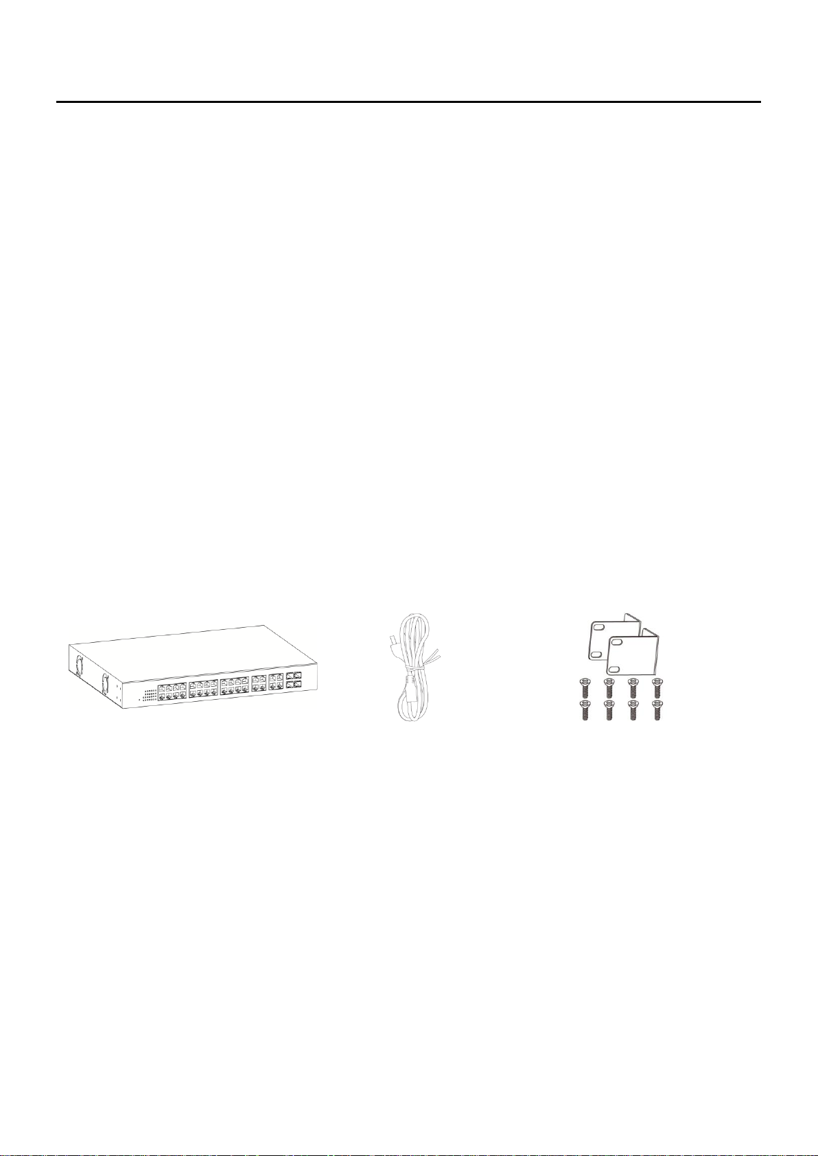
1 2 3
1. GS-5424PLC Switch
2. Power Cord
3. Rack-Mount Kit & Screws
I Introduction
Thank you for choosing a Edimax (PoE) WEB Smart Ethernet Switch. This device is
designed to be operational right out-of-the-box as a standard bridge. In the default
configuration, it will forward packets between connecting devices after powered up.
Before you begin installing the switch, make sure you have all of the package contents
available, and a PC with a web browser for using web-based system management tools.
I-1 Overview
The Edimax ES-5424P is 24-Port Gigabit PoE+ Smart Managed Switch with 4 RJ45/SFP
Combo respectively.
I-2 Package Content
Before using the product, check that the items listed below are included and in good
condition. If any item does not accord with the table, please contact your dealer
immediately.
1
Page 8
No.
Name
Description
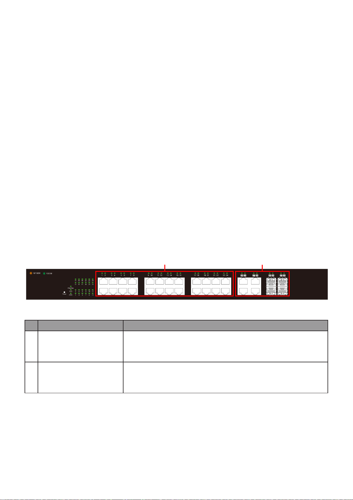
1
10/100/1000Mbps
RJ-45 ports (1-24)
Designed to connect to network devices with a bandwidth
of 10Mbps, 100Mbps or 1000Mbps. Each has a
corresponding 10/100/1000Mbps LED.
2
RJ45/SFP combo Ports
(SFP1, SFP2, SFP3, and
SFP4)
Designed to install SFP modules or RJ-45 connect to network
devices with a bandwidth of 1000Mbps. Each has a
corresponding 1000Mbps LED.
1
2
I-3 Features
Supports up to 24 10/100/1000Mbps Ethernet ports and 4 SFP slots or 4 mini-
GBIC/SFP slots
IEEE 802.3af/at PoE compliant to simplify deployment and installation
Supports PoE up to 30W per port with 400W total power budget
Automatically detects powered devices (PD) and power consumption levels
IEEE 802.1Q VLAN allows network segmentation to enhance performance and
security
Supports Access Control List (ACL)
Switch capacity: PG28CB: 56Gbps, Forwarding rate: 41.6Mbps
Supports IGMP Snooping V1 / V2 / V3
8K MAC address table and 10K jumbo frames
19-inch rack-mountable metal case
I-4 Product Components
I-4-1 Ports
The following view applies to ES-5424P.
Figure 1 - Front View
2
Page 9
No.
Name
Description
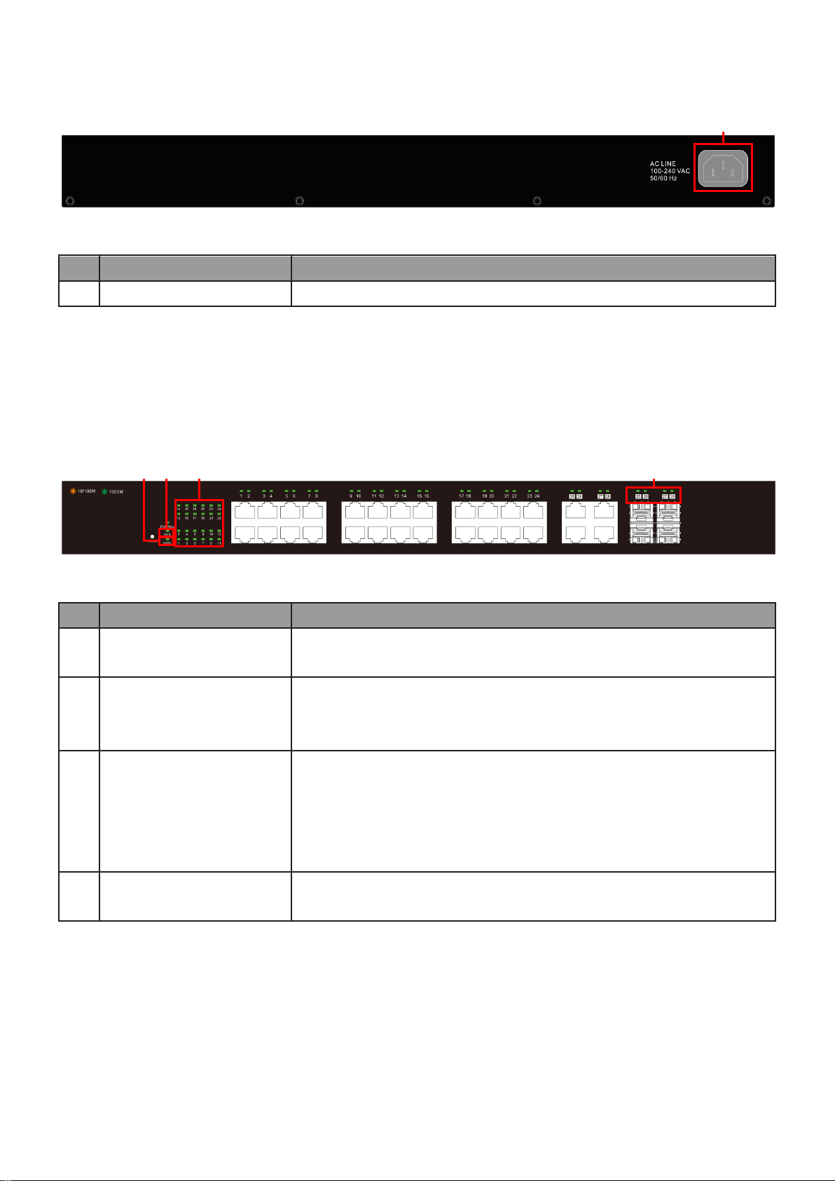
1
AC power in
Support AC100 – 240V 50-60Hz.
No.
Name
Description
1
Power
Off: power off
On: power on
2
System
Off: system not ready
On: system ready
Blinking: system boot-up
3
Port LED
LINK/ACT bi-color LED:
Off: port disconnected or link fail
Green on: 1000Mbs connected, PoE power output on
Amber on: 10/100Mbs connected
Blinking: sending or receiving data
4
SFP LED
Off: port disconnected or link fail
Green on: 1000Mbs connected
1 1 2 3 4
The following view applies to ES-5424P.
Figure 2 - Rear View
I-4-2 LED Indicators
The following view applies to ES-5424P.
Figure 3 - Front View LED Indicators
3
Page 10

II Installation
This chapter describes how to install and connect your Edimax Switch. Read the following
topics and perform the procedures in the correct order. Incorrect installation may cause
damage to the product.
II-1 Mounting the Switch
There are two ways to physically set up the switch.
Place the switch on a flat surface. To place the switch on a desktop, install the four
rubber feet (included) on the bottom of the switch.
Mount the switch in a standard rack (1 rack unit high).
II-1-1 Placement Tips
Ambient Temperature — To prevent the switch from overheating, do not operate it
in an area that exceeds an ambient temperature of 122°F (50°C).
Air Flow — Be sure that there is adequate air flow around the switch.
Mechanical Loading — Be sure that the switch is level and stable to avoid any
hazardous conditions.
Circuit Overloading — Adding the switch to the power outlet must not overload that
circuit.
Follow these guidelines to install the switch securely.
Put the switch in a stable place such as a desktop, to avoid it falling.
Ensure the switch works in the proper AC input range and matches the voltage
labeled.
Ensure there is proper heat dissipation from and adequate ventilation around the
switch.
Ensure the switch’s location can support the weight of the switch and its accessories.
Figure 4 - Desktop Installation
4
Page 11
II-1-2 Rack Mounting
You can mount the switch in any standard size, 19-inch (about 48 cm) wide rack. The
switch requires 1 rack unit (RU) of space, which is 1.75 inches (44.45 mm) high.
For stability, load the rack from the bottom to the top, with the heaviest devices on the
bottom. A top-heavy rack is likely to be unstable and may tip over.
When mounting smaller switch products into a standard 19-inch rack, a pair of extension
brackets (sometimes referred to as ears) are needed to adapt the switch to the rack size.
These extension brackets are mounted on the switch using the screws provided in the kit,
and have two holes that are used to then screw the switch into the rack.
An example of one type of these extension brackets is shown in the following figure.
A common problem that occurs during rack mounting is the distance between the screw
holes on the rack. Some racks are made with a uniform distance between all of the holes,
and others have the holes organized into groups (see photo on the next page for an
example).
When organized into groups, the switch must be placed in the rack so that the holes in
the extension brackets line up correctly.
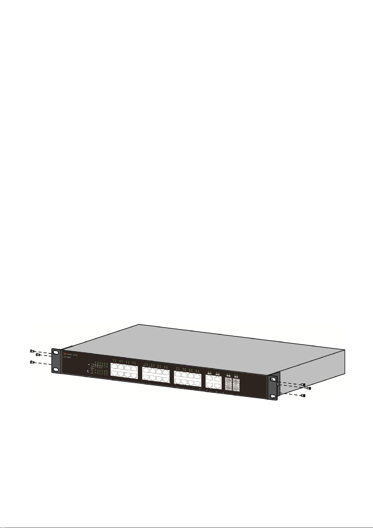
1. Align the mounting brackets with the mounting holes on the switch’s side panels
and secure the brackets with the screws provided.
Figure 5 - Bracket Installation
5
Page 12
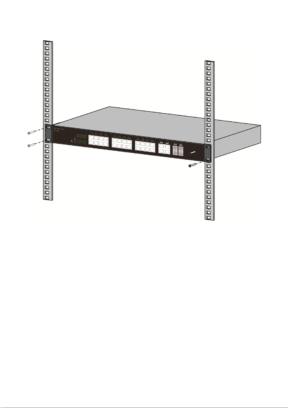
2. Secure the switch on the equipment rack with the screws provided.
Figure 6 - Rack Installation
6
Page 13

III Getting Started
This section provides an introduction to the web-based configuration utility, and
covers the following topics:
Powering on the device
Connecting to the network
Power over Ethernet (PoE) considerations
Starting the web-based configuration utility
III-1 Power
III-1-1 Connecting to Power
Power down and disconnect the power cord before servicing or wiring a switch.
Do not disconnect modules or cabling unless the power is first switched off. The device
only supports the voltage outlined in the type plate. Do not use any other power
components except those specifically designated for the switch.
Disconnect the power cord before installation or cable wiring.
The switch is powered by the AC 100-240 V 50/60Hz internal high-performance power
supply. It is recommended to connect the switch with a single-phase three-wire power
source with a neutral outlet, or a multifunctional computer professional source.
Connect the AC power connector on the back panel of the switch to the external power
source with the included power cord, and check the power LED is on.
Figure 7 - Rear View AC Power Socket
7
Page 14
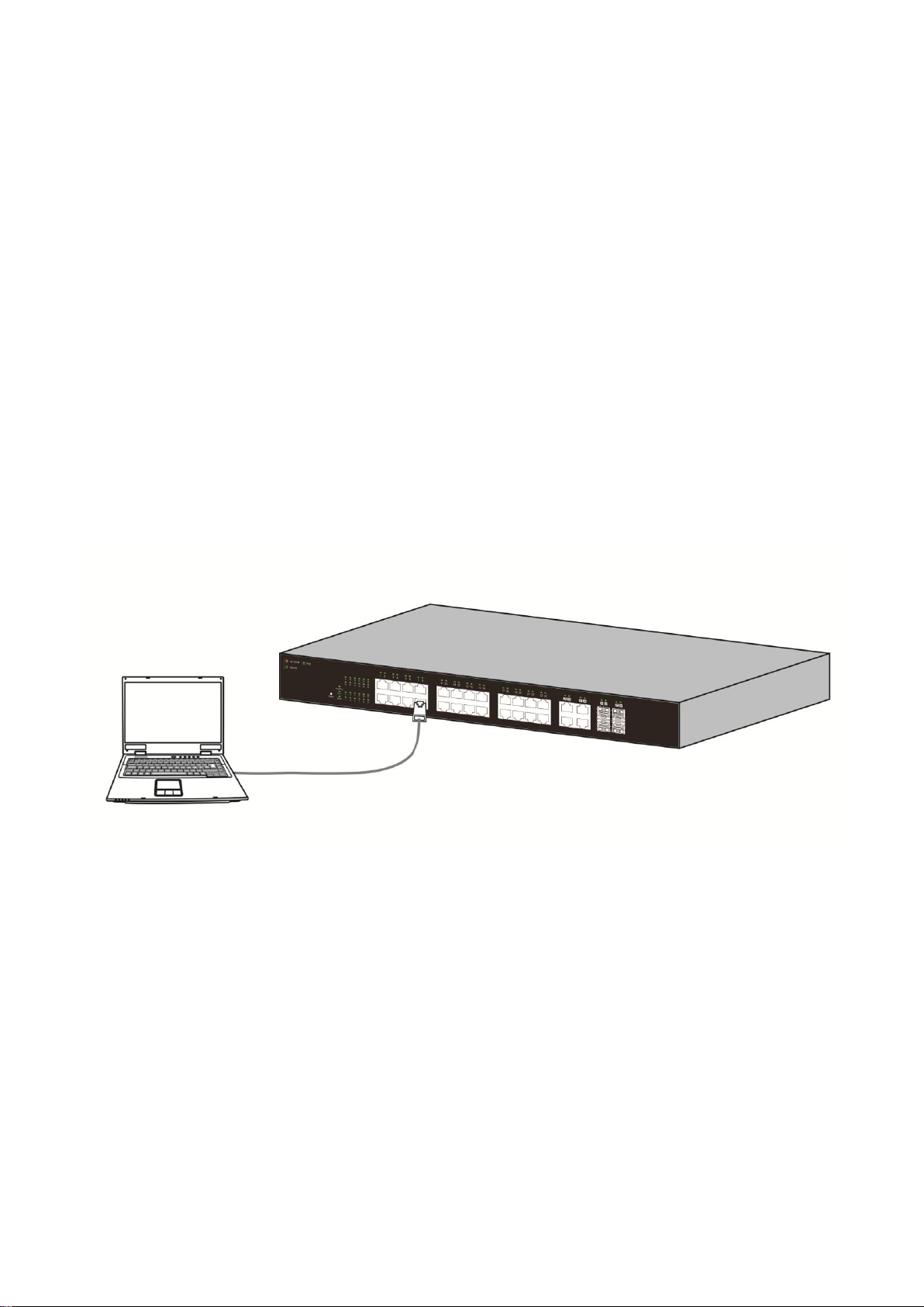
III-1-2 Connecting to Network
To connect the switch to the network:
1. Connect an Ethernet cable to the Ethernet port of a computer
2. Connect the other end of the Ethernet cable to one of the numbered Ethernet
ports of the switch. The LED of the port lights if the device connected is active.
3. Repeat Step 1 and Step 2 for each device to connect to the switch.
We strongly recommend using CAT-5E or better cable to connect network devices. When
connecting network devices, do not exceed the maximum cabling distance of 100 meters
(328 feet). It can take up to one minute for attached devices or the LAN to be operational
after it is connected. This is normal behavior.
Connect the switch to end nodes using a standard Cat 5/5e Ethernet cable (UTP/STP) to
connect the switch to end nodes as shown in the illustration below.
Switch ports will automatically adjust to the characteristics (MDI/MDI-X, speed, duplex)
of the device to which the switch is connected.
Figure 8 - PC Connect
8
Page 15

Model
Power Dedicated to PoE
PoE Ports
PoE Standard Supported
ES-5424P
240W
1 to 24
IEEE802.3at/af
III-1-3 Power over Ethernet (PoE) Considerations
For PoE switch models, consider the following information:
Devices considered a Power Sourcing Equipment (PSE), can support up to 30 Watts per
PoE port to a Powered Device (PD).
Ports 1-24 provide PoE power supply functionality with a maximum output power up to
30W each port. This can supply power to PDs such as internet phones, network cameras,
wireless access points. Connect the switch PoE port directly to the PD port using a
network cable.
When connecting switches capable of supplying PoE, consider the following information:
Switch models with PoE function are PSEs. These models are capable of supplying DC
power to attached PDs, such as VoIP phones, IP cameras, and wireless access points
(APs). PoE switches. Additionally, PoE switches are capable of detecting and
supplying power to pre-standard legacy PoE Power Devices. Due to the support for
legacy PoE, there is a possibility that PoE switches acting as a PSE may inadvertently
detect and supply power an attached PSE, including other PoE switches. This false
detection may result in a PoE switch operating improperly and unable to supply
power to attached PDs.
The prevention of a false detection can be easily remedied by disabling PoE on the
ports that are used to connect PSEs. Another simple practice to prevent a false
detection is to first power up a PSE device before connecting it to a PoE switch.
When a device is falsely detected as a PD, disconnect the device from the PoE port
and power recycle the device with AC power before reconnecting it to the PoE port.
9
Page 16
III-1-4 Starting the Web-based Configuration Utility
This section describes how to navigate the web-based switch configuration utility.
Be sure to disable any pop-up blocker.
Browser Restrictions
If you are using older versions of Internet Explorer, you cannot directly use an IPv6
address to access the device. You can, however, use the DNS (Domain Name System)
server to create a domain name that contains the IPv6 address, and then use that
domain name in the address bar in place of the IPv6 address.
If you have multiple IPv6 interfaces on your management station, use the IPv6 global
address instead of the IPv6 link local address to access the device from your browser.
Launching the Configuration Utility
To open the web-based configuration utility:
1. Open a Web browser.
2. Enter the IP address of the device you are configuring in the address bar on the
browser (factory default IP address is 192.168.2.1) and then press Enter.
When the device is using the factory default IP address, its power LED flashes
continuously. When the device is using a DHCP assigned IP address or an administrator-
configured static IP address, the power LED is lit a solid color. Your computer’s IP address
must be in the same subnet as the switch. For example, if the switch is using the factory
default IP address, your computer’s IP address can be in the following range: 192.168.2.x
(whereas x is a number from 2 to 254).
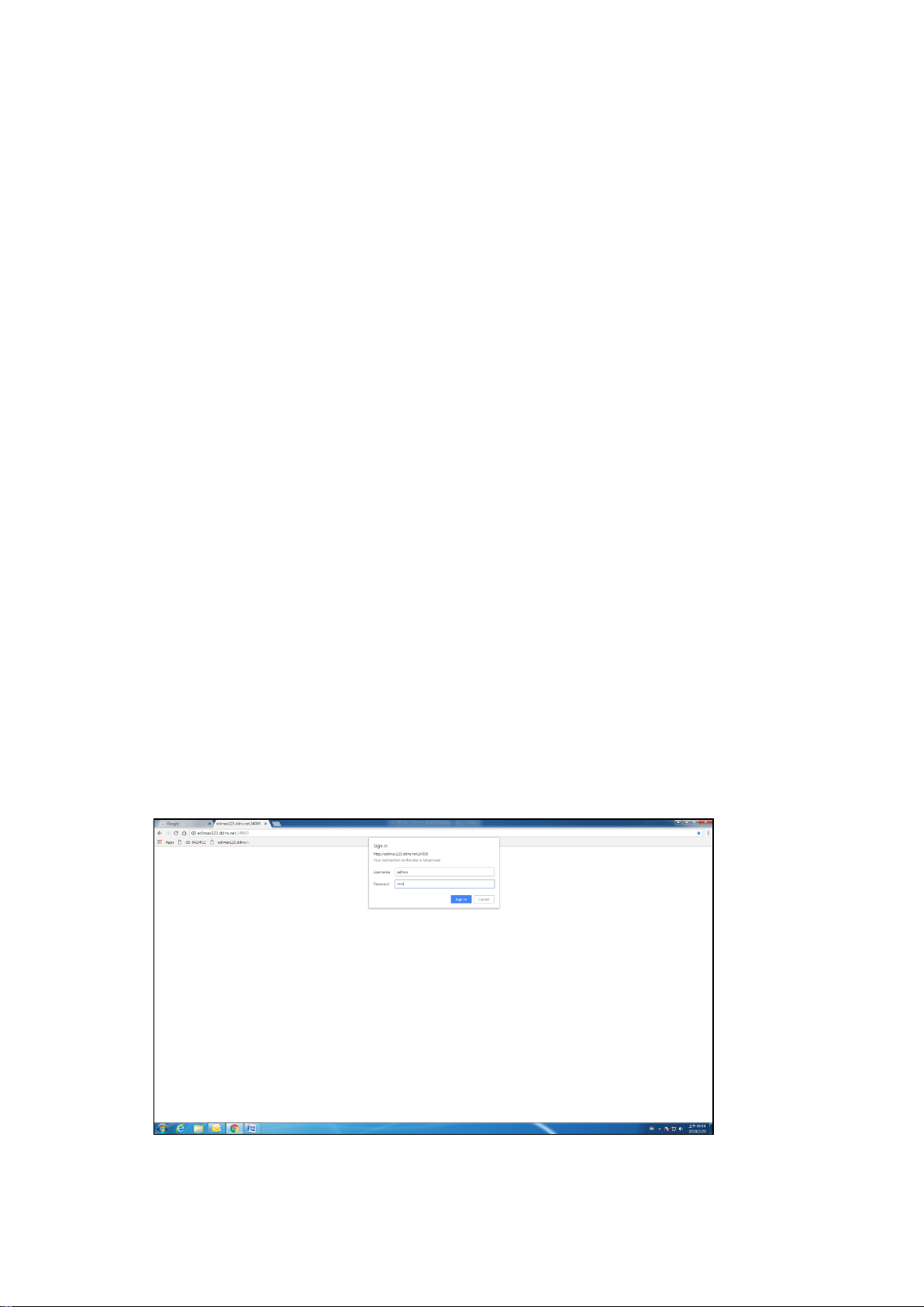
After a successful connection, the login window displays.
Figure 9 - Login Window
10
Page 17
III-1-5 Logging In
The default username is admin and the default password is 1234. The first time that you
log in with the default username and password, you are required to enter a new
password.
To log in to the device configuration utility:
1. Enter the default user ID (admin) and the default password (admin).
2. If this is the first time that you logged on with the default user ID (admin) and the
default password (admin) it is recommended that you change your password
immediately. See “4.9.3. Administrator” for additional information.
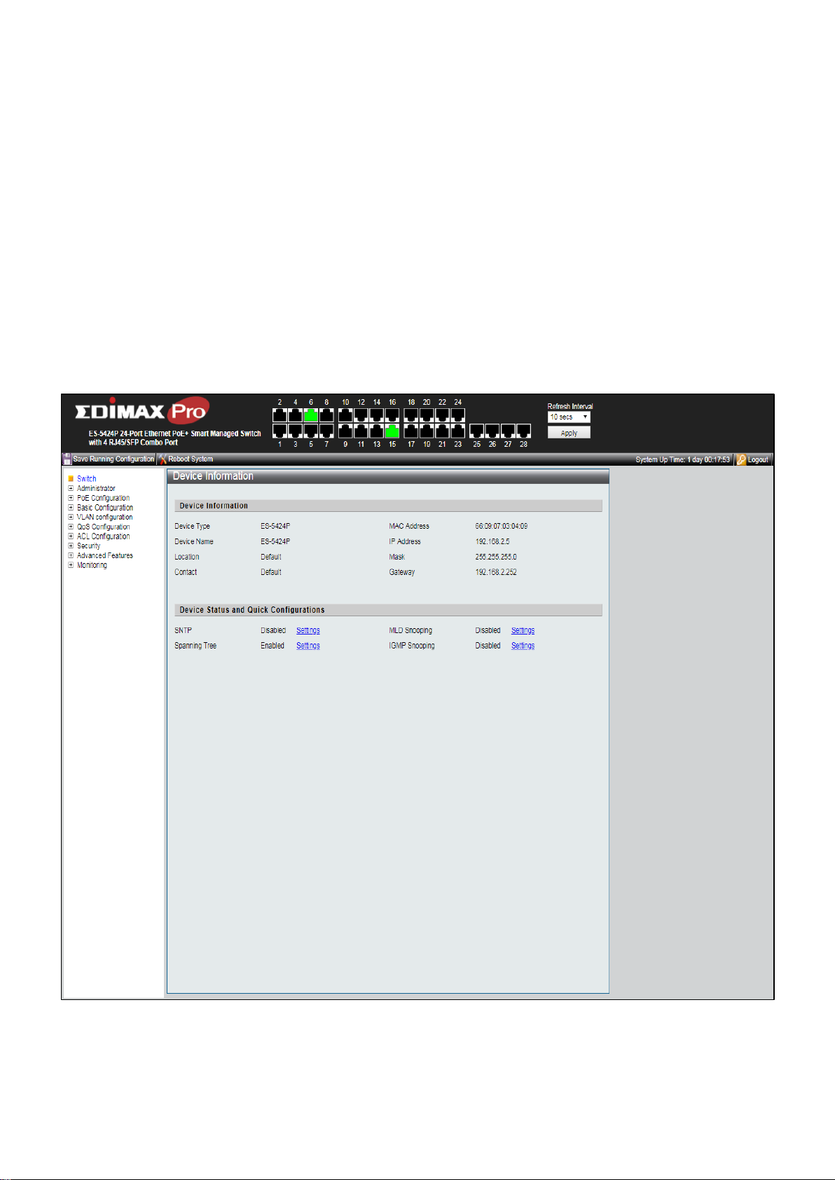
When the login attempt is successful, the System Information window displays.
Figure 10 - System Information
11
Page 18

If you entered an incorrect username or password, an error message appears and the
Login page remains displayed on the window.
If you are having problems logging in, please see the Launching the Configuration Utility
section in the Administration Guide for additional information.
III-1-6 Logging Out
By default, the application logs out after ten minutes of inactivity.
To manually logout, click Logout in the top right corner of any page.
When a timeout occurs or you intentionally log out of the system, a message appears and
the Login page appears, with a message indicating the logged-out state. After you log in,
the application returns to the initial page.
12
Page 19
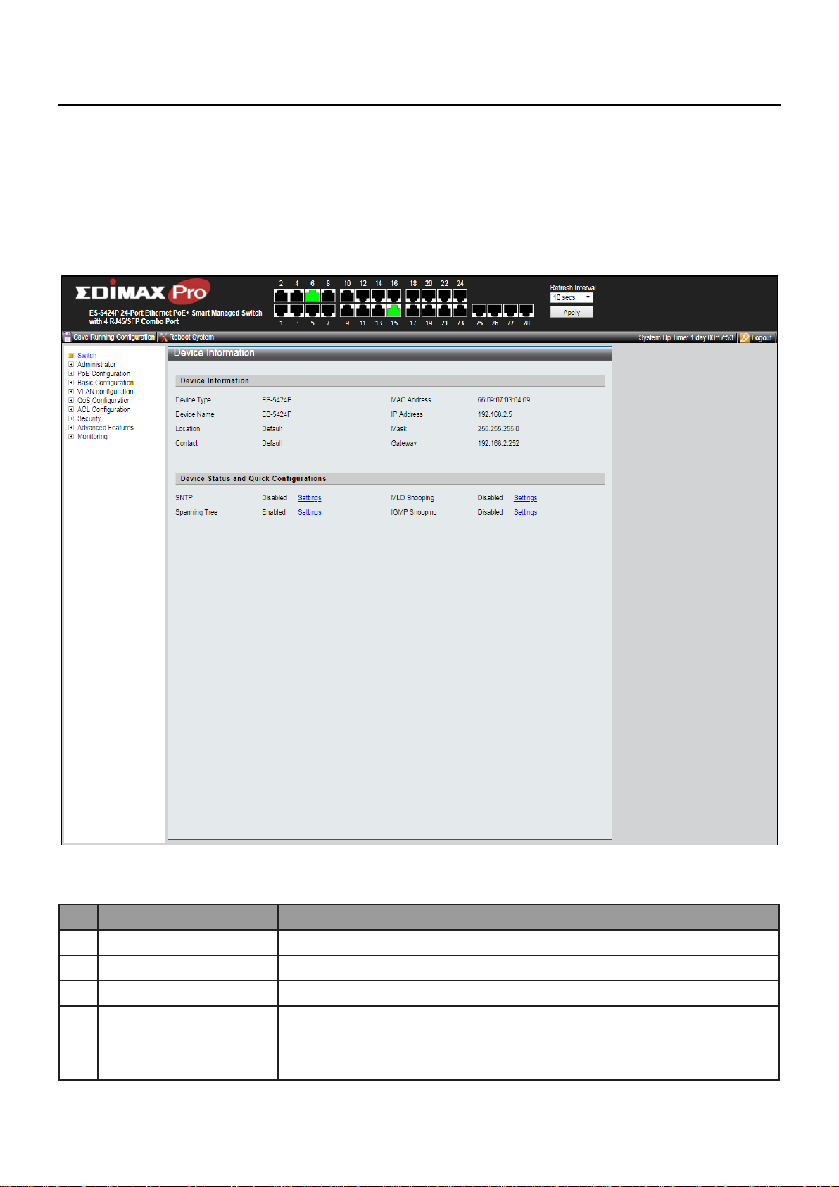
No.
Name
Description
1
Configuration menu
Navigate to locate specific switch functions.
2
Configuration settings
Edit specific function settings.
3
Switch’s information
Provides device information
4
Common toolbar &
Switch’s current link
status
Provides access to frequently used settings. Green squares
indicate the port link is up, while black squares indicate the
port link is down.
4
2
1
IV Web-based Switch Configuration
The PoE smart switch software provides rich Layer 2 functionality for switches in your
networks. This chapter describes how to use the web-based management interface (Web
UI) to configure the switch’s features.
For the purposes of this manual, the user interface is separated into four sections, as
shown in the following figure:
Figure 11 - User Interface
13
Page 20
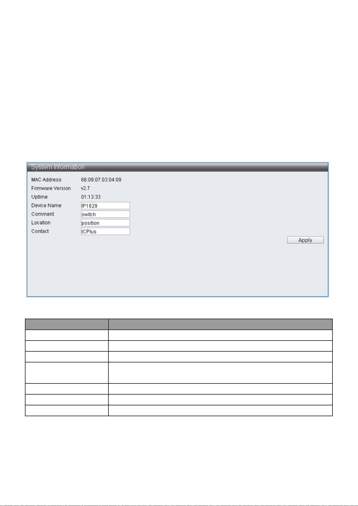
Item
Description
MAC Address
Base MAC address of the switch.
Firmware Version
Current running firmware image version.
Uptime
Display uptime.
Device Name
System name of the switch. This name will also use as CLI prefix
of each line. (“Switch>” or “Switch#”).
Comment
Edit switch’s application.
Location
Edit switch’s location.
Contact
Edit switch’s content.
IV-1 Administrator
Use the Administrator pages to view system information and status.
IV-1-1 System Information
This page shows switch’s MAC Address, Firmware Version, Uptime, Device name,
Comment, Location and Contact information. It also allows user to edit some system
information.
To display the Device Information web page, click Administrator > System Information.
Note: Up to 15 characters can be entered.
Figure 12 - Administrator > System Information
Only the Device name, Comment, Location and Contact fields are able to be edited. Click
“Apply” button on the table to apply the changes made.
14
Page 21
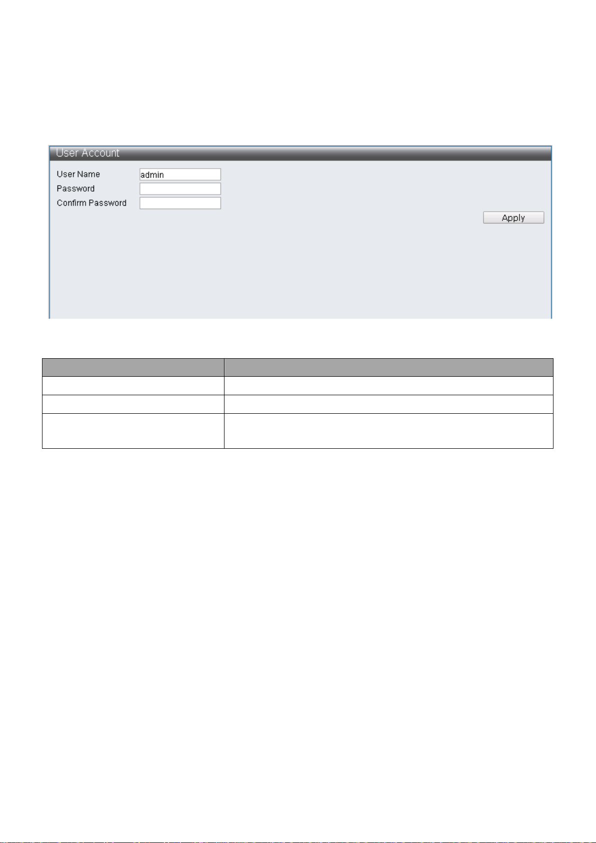
Item
Description
User Name
Edit username
Password
Set password of the account.
Confirm Password
Set the same password of the account as in “Password”
field.
IV-1-2 Account / Password
This page displays the account and password that must be entered to log on the interface.
To display the User Account web page, click Administrator > Account / Password.
Figure 13 - Administrator > Account / Password
Note: Up to 15 characters can be entered.
Enter the desired username and password. Click “Apply” button on the table to apply the
changes made.
15
Page 22
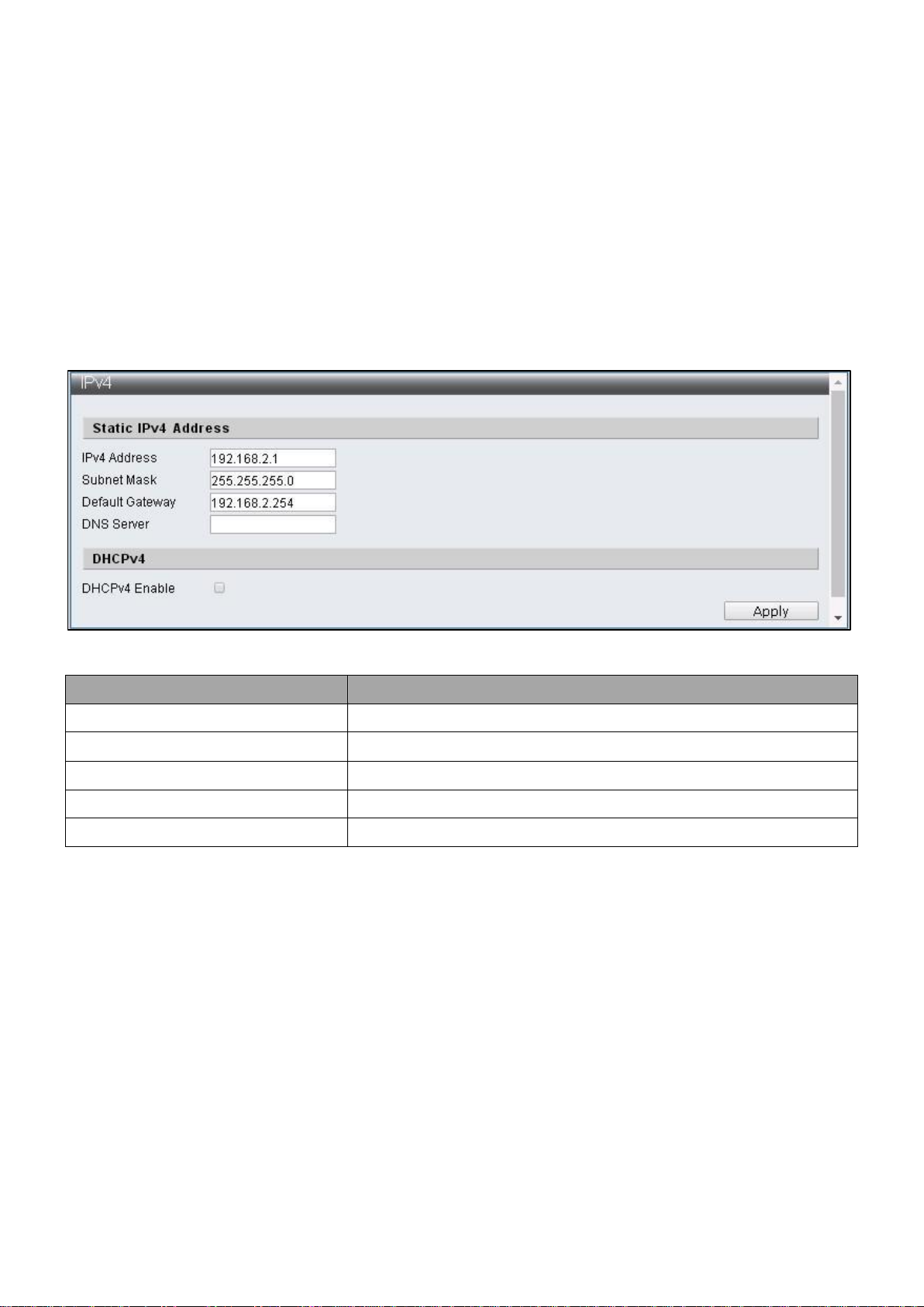
Item
Description
IPv4 Address
Edit IPv4 Address
Subnet Mask
Edit IPv4 Subnet Mask
Default Gateway
Edit IPv4 Default Gateway
DNS Server
Edit IPv4 DNS Server
DHCPv4 Enable
Enable IPv4 DHCP Server
IV-1-3 IP Configuration
IP Configuration allows users to assign IPv4 Address and IPv6 Address, or the IPv4
Address and IPv6 Address are automatically generated by DHCP Server.
IV-1-3-1 IPv4
This section allows you to configure the IPv4 address.
To display the IPv4 web page, click Administrator > IP Configuration > IPv4.
Figure 14 - Administrator > IP Configuration > IPv4
Note: The characters allowed to be entered are combinations of “0~9” and “.”.
16
Page 23
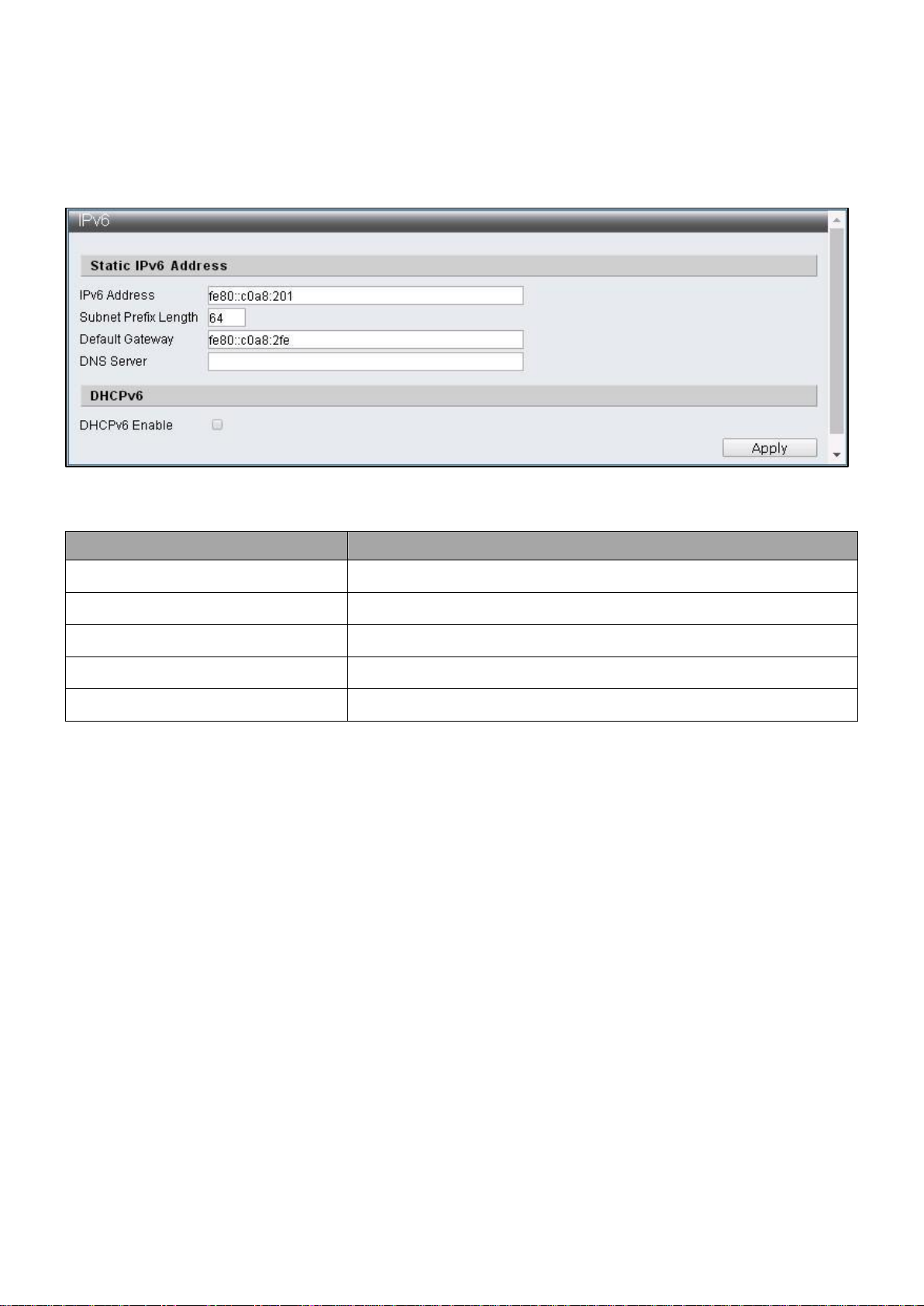
Item
Description
IPv6 Address
Configure IPv6 Address
Subnet Prefix Length
Configure IPv6 Subnet Prefix Length
Default Gateway
Configure IPv6 Default Gateway
DNS Server
Configure IPv6 DNS Server
DHCPv6 Enable
Enable IPv6 DHCP Server
IV-1-3-2 IPv6
This section allows you to configure the IPv6 address.
To display the IPv4 web page, click Administrator > IP Configuration > IPv6.
Figure 15 - Administrator > IP Configuration > IPv6
Note: The characters allowed to be entered are combinations of “0~9”, “a~f” and “.”.
IV-1-4 SNMP Settings
SNMP
Simple Network Management Protocol (SNMP) is an Internet Standard protocol for
collecting and organizing information about managed devices on IP networks. The core
of SNMP is a simple operation program enabling management to monitor SNMP
supported devices (hereafter referred to as agent). Simple Network Management
Protocol (SNMP) consists of three parts including SNMP, MIB (Management Information
Base) and SMI (Structure of Management Information). The SMI defines basic data
types that make it convenient to describe managed objects and their behaviors.
A management information base (MIB) is a database used for managing the entities in
a communication network. MIB describe the system status and configuration.
SNMP supports SNMPv1, SNMPv2 and SNMPv3, different versions can be selected to
monitor Switch. The security levels provided by three versions in network management
are different. The user authentication of SNMPv1 and SNMPv2 is done by community
string, which functions as password. The manager and agent has to use the same
community string in order to communicate. SNMPv3 use more complicated
authentication and additional security levels to encrypt the packets.
17
Page 24
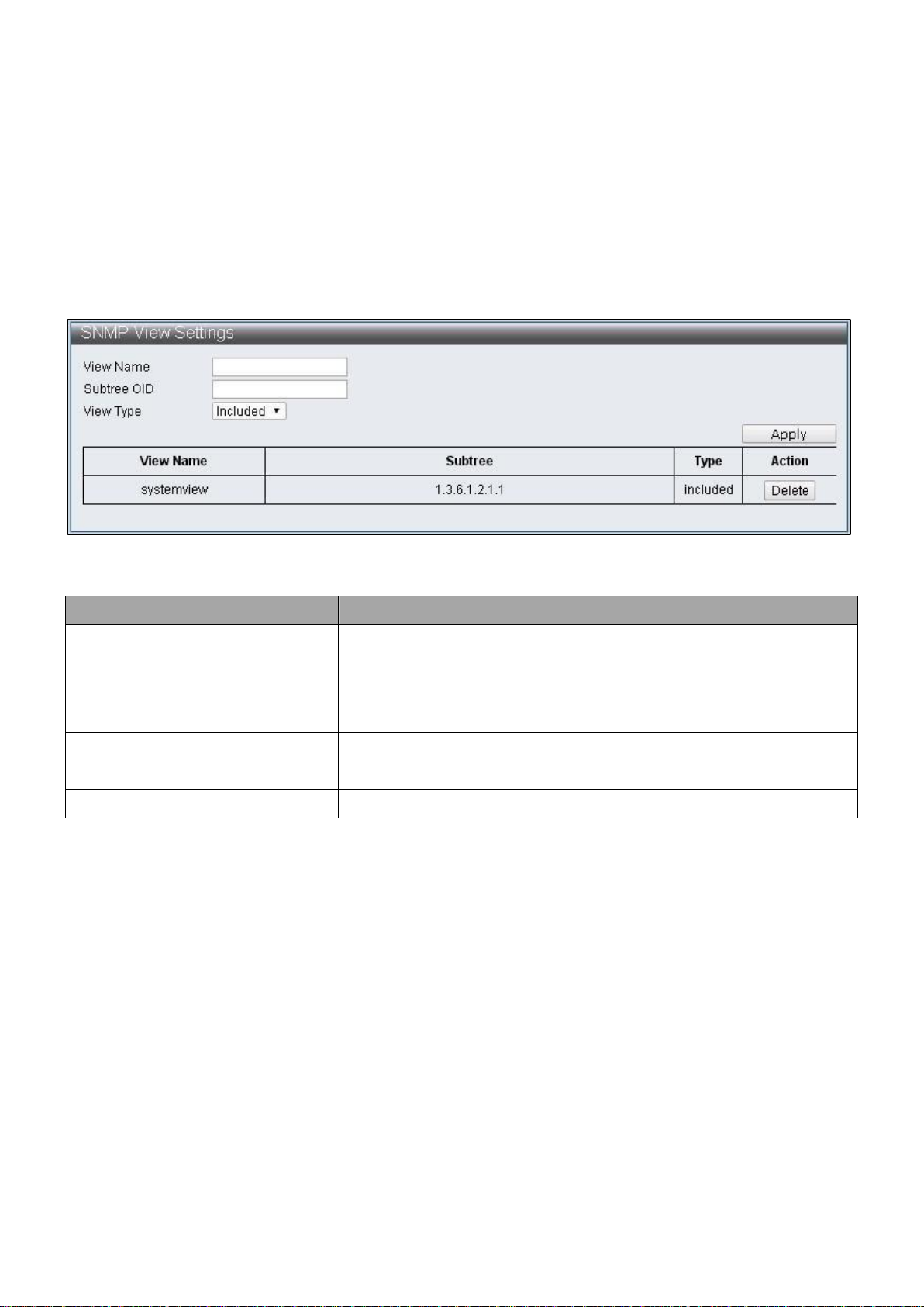
Item
Description
View Name
The SNMP view name. Its maximum length is 20
characters
Subtree OID
The OID identifies an object tree (MIB tree) that will be
included or excluded
View Type
Specify the configured OID is Included or Excluded that an
administrator can access
Delete
Remove the existing view
Trap is an unsolicited message sent by an SNMP agent to an SNMP manager when some
event has occurred. Examples of trap conditions include, but are not limited to, when a
port or module goes up or down, when the device is restarts, etc. Managers can
designate type of event to be notified.
IV-1-4-1 SNMP View Table
To configure and display the SNMP view table, click Administrator > SNMP Settings >
SNMP View Table.
Figure 16 - Administrator > SNMP Settings > SNMP View Table
18
Page 25
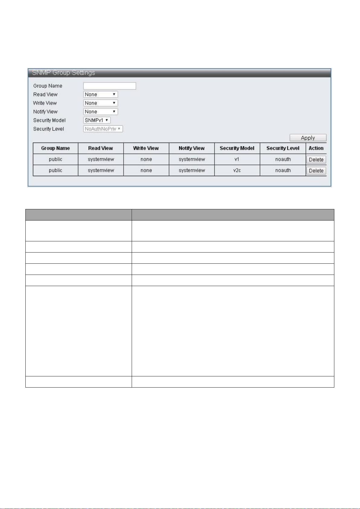
Item
Description
Group Name
Specify SNMP group name, and the maximum length is 20
characters.
Read View
Specify read access for the newly added group
Write View
Specify write access for the newly added group
Notify View
Specify Trap View for the newly added group
Security Model
Specify the SNMP version for the newly added group
Security Level
Specify SNMP security level for the newly added group,
only support SNMPv3
NoAuthNoPriv –No authorization and no encryption
for packets sent
AuthNoPriv –Authorization is required, but no
encryption for packets sent
AuthPriv – Both authorization and encryption are
required for packets sent
Delete
Remove the existing group
IV-1-4-2 SNMP Group Table
To configure and display the SNMP group table, click Administrator > SNMP Settings >
SNMP Group Table.
Figure 17 - Administrator > SNMP Settings > SNMP Group Table
19
Page 26
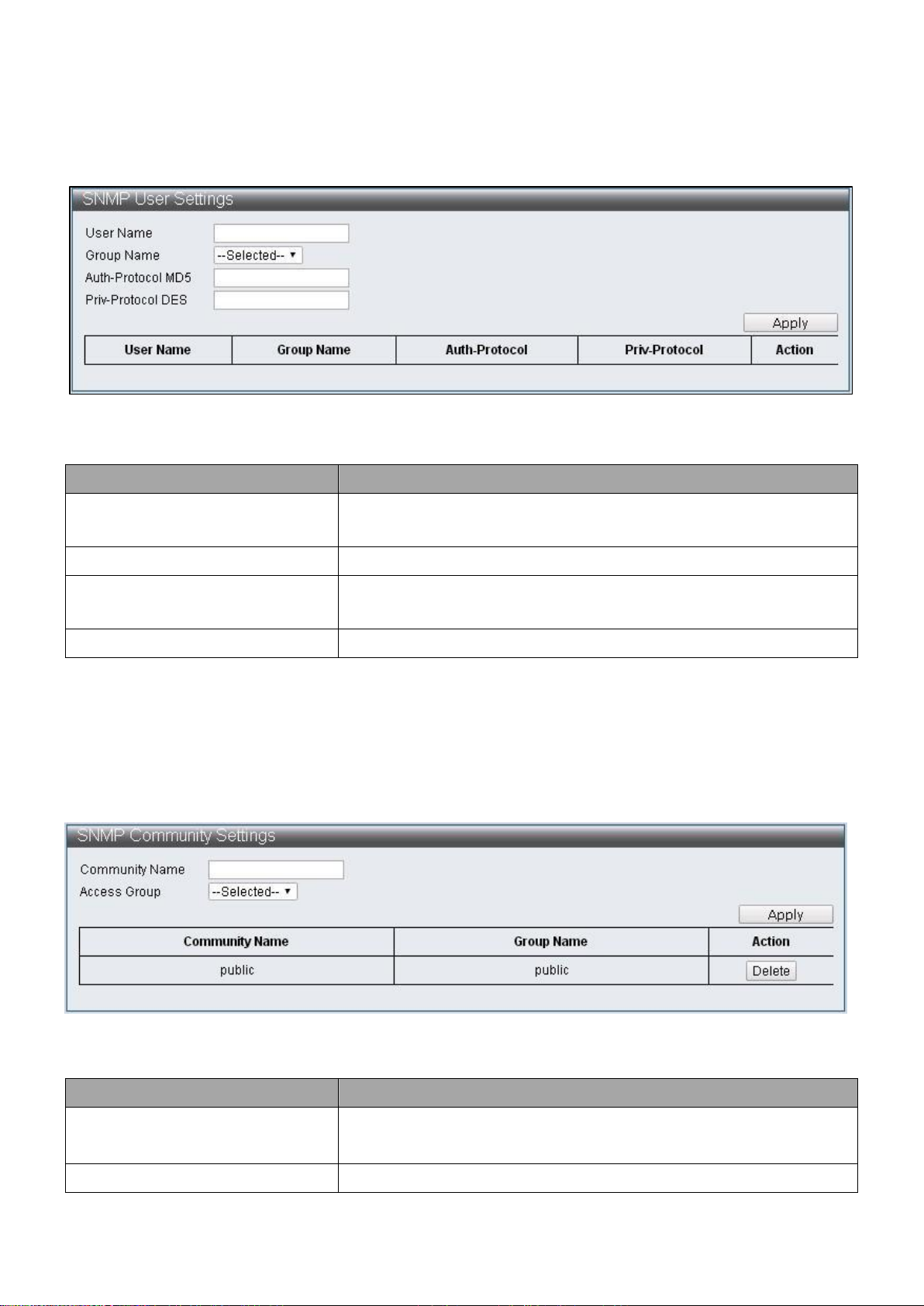
Item
Description
User Name
Specify SNMP user name, and the maximum length is 20
characters
Group View
Specify the SNMP group to which the SNMP user belongs.
Auth-Protocol MD5
Specify authentication protocol, MD5 authentication level
is used
Priv-Protocol DES
Specify encryption protocol, DES 56-bits encryption is used
Item
Description
Community Name
Specify the name for new SNMPv1 / SNMPv2 community
string, its maximum length is 20 characters
Access Group
Specify the SNMP group to which the SNMP user belongs
IV-1-4-3 SNMP User Table
To configure and display the SNMP user table, click Administrator > SNMP Settings >
SNMP User Table.
Figure 18 - Administrator > SNMP Settings > SNMP User Table
IV-1-4-4 SNMP Community Table
To configure and display the SNMP community table, click Administrator > SNMP
Settings > SNMP Community Table.
Figure 19 - Administrator > SNMP Settings > SNMP Community Table
20
Page 27

Item
Description
Host IP Address
Specify the IP address of SNMP Trap
Security Model
Specify the SNMP version
Security Level
Specify SNMP security level, only support SNMPv3
NoAuthNoPriv –No authorization and no
encryption for packets sent
AuthNoPriv –Authorization is required, but no
encryption for packets sent
AuthPriv – Both authorization and encryption are
required for packets sent
Community String/SNMPv3 User
Specify the community string or SNMPv3 user name
IV-1-4-5 SNMP Host Table
To configure and display the SNMP host table, click Administrator > SNMP Settings >
SNMP Host Table.
Figure 20 - Administrator > SNMP Settings > SNMP Host Table
21
Page 28
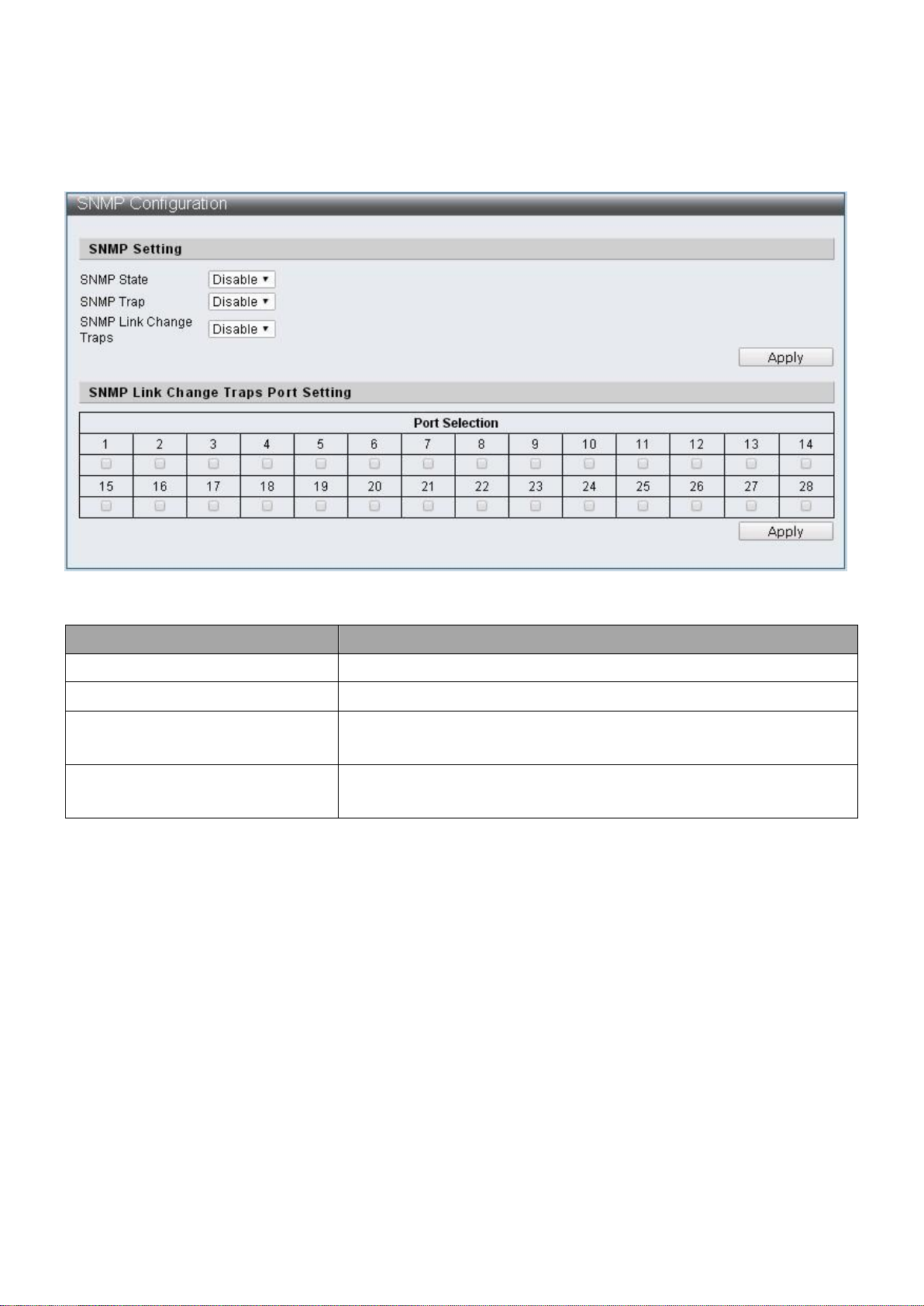
Item
Description
SNMP State
Enable / Disable SNMP state
SNMP Trap
Enable / Disable SNMP Trap
SNMP Link Change Traps
Enable / Disable to send trap to remote host when link
changes
Port Selection
Check off the port that needs to be enabled to send traps
for link changes detection
IV-1-4-6 SNMP Configuration
To configure and display the SNMP Configuration, click Administrator > SNMP Settings >
SNMP Configuration.
Figure 21 - Administrator > SNMP Settings > SNMP Configuration
22
Page 29
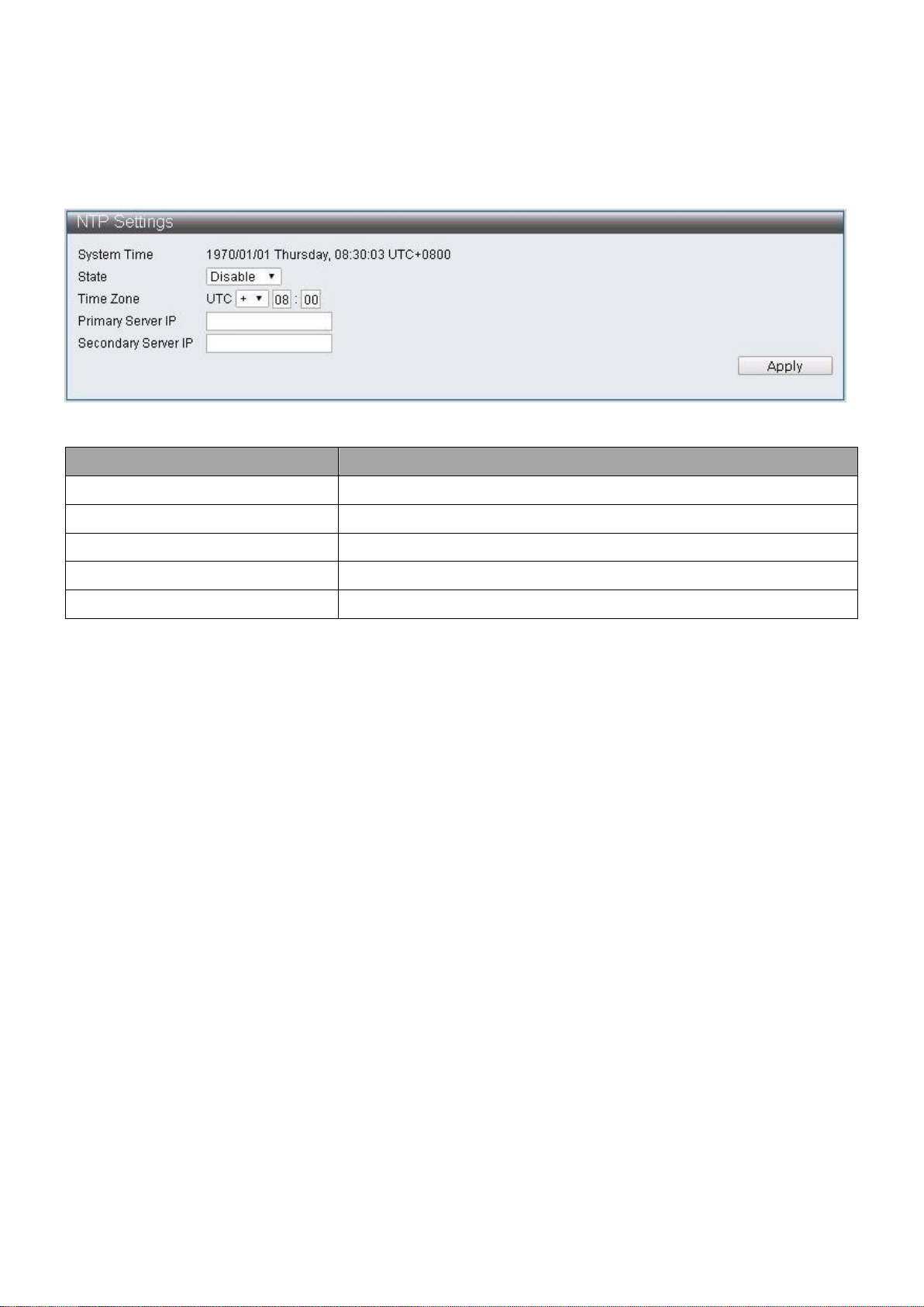
Item
Description
System Time
Display system time
State
Enable / Disable NTP state
Time Zone
Specify timezone
Primary Server IP
Primary Server IP
Secondary Server IP
Secondary Server IP
IV-1-5 NTP Settings
The NTP (Network Time Protocol) provide network time verification.
To configure and display the NTP Settings, click Administrator > NTP Settings
Figure 22 - Administrator > NTP Settings
23
Page 30
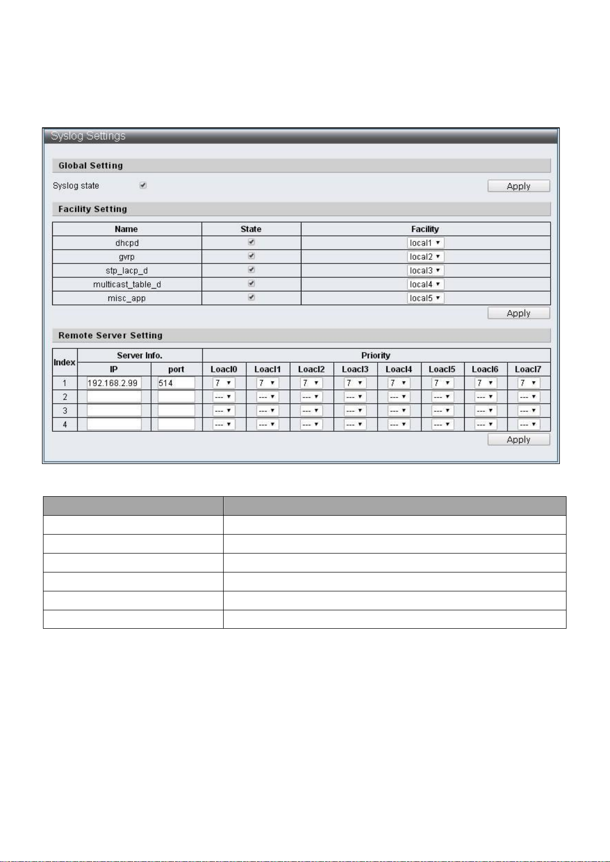
Item
Description
Syslog state
Enable Syslog
Name
Protocol
State
Enable / Disable protocol
Facility
Select Local number
Server Info.
Specify the server IP Address and port number
Priority
Select Local priortiy
IV-1-6 Syslog Settings
This page allow users to configure syslog.
To configure and display the Syslog Settings, click Administrator > Syslog Settings.
Figure 23 - Administrator > Syslog Settings
24
Page 31

Item
Description
Load Default
Reset the Switch to the factory default settings
IV-1-7 Load Factory Default
To reset the Switch to the factory default settings.
To configure and display the Load Factory Default, click Administrator > Load Factory
Default.
Figure 24 - Administrator > Load Factory Default
Note: Load Factory Default will reset the action pattern of ES-5424P to factory default
setting but User Name, Password and IP Address will not be affected.
25
Page 32

IV-1-8 Configuration
This page allows users to configure ES-5424P web Backup and Restore. A configuration
profile, current.tar.gz will be generated and saved through Backup by users, it contains
the current configuration of ES-5424P web. When users wish to restore the previous
configuration, current.tar.gz can be selected through Restore to overwrite the current
setting.
IV-1-8-1 Backups
To configure and display the Load Factory Default, click Administrator > Configuration >
Backup.
After clicking “Apply” Button, current.tar.gz configuration profile will be automatically
downloaded and saved to the directory assigned by users.
Figure 25 - Administrator > Configuration > Backup.
IV-1-8-2 Restore
To configure and display the Restore, click Administrator > Configuration > Restore
Figure 26 - Administrator > Configuration > Restore
26
Page 33

Item
Description
Select File
Select current.tar.gz configuration profile to overwrite the
current setting.
Item
Description
Choose File
Select Firmware Version for update.
Note: current.tar.gz configuration profile will not change the IP Address.
IV-1-9 Firmware Update
This page allows users to update ES-5424P Firmware versions. Click “Choose File” to
select the location where upgrade file is stored, then click the “Apply” to execute
Firmware Update. The update is completed when waiting time ended.
To configure and display the Firmware Update, click Administrator > Firmware Update.
Figure 27 - Administrator > Firmware Update
IV-2 Port Management
IV-2-1 Port Configuration
This page, Port Configuration, allows users to configure every port, including
settings of Power up/down, Speed, Duplex, Auto-negotiation, Flow control,
Address learning and Port name.
To configure and display the Port Configuration, click Basic Configuration > Port
Configuration.
27
Page 34

Item
Description
Port Selection
Select the port
Settings
Current configuration
Status
The current link status
State
Power up/down
Speed/Duplex
Select port speed and duplex
Auto Negotiation
Enable / Disable Auto-negotiation
Flow Control
Enable / Disable Flow control
Address Learning
Enable / Disable address learning
Name
Specify the port name
Refresh
Refresh the page
Figure 28 - Basic Configuration > Port Configuration
28
Page 35

Item
Description
Source Port Selection
Select the number of the ports whose network activity
will be monitored.
Destination Port Selection
Select the number of the port that will be used to
monitor the activity of the monitored port.
State
Enable / Disable monitoring function.
Method
Specify ingress, egress or both methods
IV-2-2 Port Mirror Function
Port Mirroring is a method of monitoring network traffic where the switch forwards a
copy of each incoming and/or outgoing packet from source port to destination port.
Under certain scenarios, network traffic can be monitored for other applications such as
diagnostics or management.
To configure and display the Port Mirror Function, click Basic Configuration > Port Mirror
Function.
Figure 29 - Basic Configuration > Port Mirror Function
29
Page 36
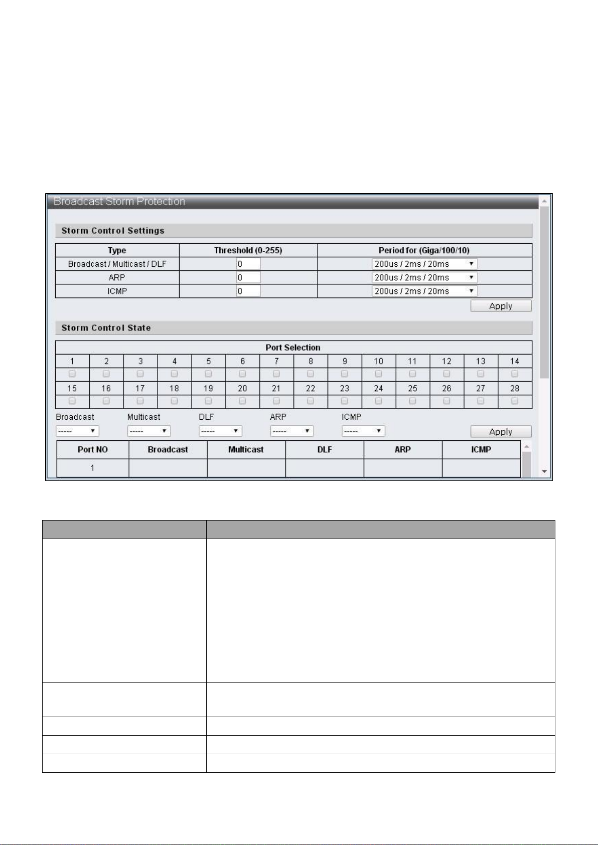
Item
Description
Type
Various storm control types:
Broadcast:broadcast packets
Multicast:one-to- many transmissions of packets and the
40-bit of destination MAC is set to 1.
DLF:the destination MAC address not included in MAC
address table
ARP:ARP packet
ICMP:ICMP packet
Threshold
The maximum number of assigned packets can be received
by port within the receival period.
Period for (Giga/100/10)
Specify the receival period.
Port Selection
Select the setting ports.
Broadcast
Enable / Disable the control on broadcast packets.
IV-2-3 Broadcast Storm Protection
The Broadcast Storm Protection feature provides the ability to control the receive rate of
broadcast, multicast, DLF, ARP and ICMP packets for every port. The maximum threshold
is 255 per time unit within the control period.
To configure and display the Broadcast Storm Protection, click Basic Configuration >
Broadcast Storm Protection.
Figure 30 - Basic Configuration > Broadcast Storm Protection
30
Page 37

Multicast
Enable / Disable the control on multicast packets.
DLF
Enable / Disable control on unknown destination MAC
packets.
ARP
Enable / Disable control on ARP packets.
ICMP
Enable / Disable control on ICMP packets.
31
Page 38
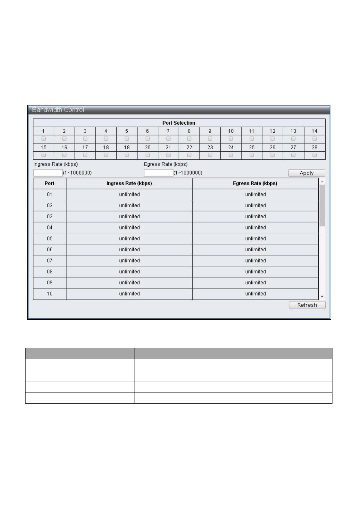
Item
Description
Port Selection
Select the settings port
Ingress Rate
Specify the rate of packet received
Egress Rate
Specify the rate of packets transmitted
Refresh
Refresh the status of bandwidth Control
IV-2-4 Bandwidth Control
This page provides the bandwidth control on transmitting and receiving data rates of
each port, the default setting is the maximum link speed.
To configure and display the Bandwidth Control, click Basic Configuration > Bandwidth
Control.
Figure 31 - Basic Configuration > Bandwidth Control
32
Page 39

Item
Description
VLAN Mode
Tag Vlan: Specify the VID of each Entry according to the Tagbased Entry setting and which port should be VLAN
members of such VID.
Group Vlan: Specify the port which is a Group VLAN
member according to Group-based Entry settings.
Tag Method
The setting is only effective under the Tag VLAN mode
By Tag: The transmitting port will add or remove tag
according to the value assigned to the port of Tag-based
Entry
By Port: The transmitting port will add or remove tags
according to the Tagging value assigned to the port of
VLAN port config web page
Egress Frame
Transmit the selected type of packets (Multicast, Unicast
and ARP) among different VLAN through egress rule
IV-3 VLAN Configuration
IV-3-1 VLAN Mode
A virtual local area network, virtual LAN or VLAN is able to configure one or more ports
into independent domain according to logic, the information between each domain is not
able to communicate; thus the bandwidth is saved and performance is increased to
provide a certain level of security for the network. The switch supports IEEE 802.1Q and
Port-Based VLAN, the untagged ports can remove the 802.1Q tag to maintain the
compatibility with equipment that does not support IEEE 802.1Q.
To configure and display the VLAN Mode, click VLAN Configuration > VLAN Mode.
Figure 32 - VLAN Configuration > VLAN Mode
33
Page 40

Item
Description
Group Name
Specify the Group VLAN name
Group Member Port
Specify Group VLAN member
Add
Add Group VLAN
Edit
Edit the selected Group VLAN
Modify
Modify the contents of selected Group VLAN
Delete
Deleted the selected Group VLAN
IV-3-2 VLAN Group-based Entry Config
To configure and display the VLAN Group-based Entry Config, click VLAN Configuration >
VLAN Group-based Entry Config.
Figure 33 - VLAN Configuration > VLAN Group-based Entry Config
34
Page 41

Item
Description
Add
Add Tag VLAN. Enter default Tag VLAN name and its VID
according to instructions
Edit
Edit the selected Tag VLAN
Delete
Delete the selected Tag VLAN
IV-3-3 VLAN Tag-based Entry Config
To configure and display the VLAN Tag-based Entry Config, click VLAN Configuration >
VLAN Tag-based Entry Config.
Figure 34 - VLAN Configuration > VLAN Tag-based Entry Config
35
Page 42

Item
Description
VLAN Name
Tag VLAN name
VID
The VID of this Tag VLAN
Priority
Specify the Tag VLAN priority
GVRP forward
When GVRP is enabled, specify if this Tag VLAN will be
transmitted through GVRP
VLAN Member
Specify the Tag VLAN member
Don’t care
It is a VLAN member
Add
It is a VLAN member, add tag to the packets transmitted by
this Port
Remove
It is a VLAN member, remove tag to the packets
transmitted by this Port
Forbidden
Configure this Port to be unable to register the Tag VLAN
through GVRP
Not member
It is not a VLAN member
Figure 35 - VLAN Configuration > VLAN Tag-based Entry Config > Edit > VLAN Tag-based
Entry config
36
Page 43

Item
Description
Port Selection
Select the settings port
PVID
Specify the Port VID
Tagging
Specify if the packets transmitted by Port should add or
remove VLAN Tag
Force VLAN Group
Specify if priority is set according to Group VLAN
Uplink
Configure as uplink port. When the destination Port of
packets are not in the same VLAN, packets will be
transmitted from uplink port automatically
Exclusive
Configure as exclusive port, packets cannot be transmitted
between exclusive ports
Egress
Configure as egress port, when the destination port of
packets is not in the same VLAN, such packets can still be
transmitted to the destination port through egress rule
IV-3-4 VLAN Port Config
To configure and display the VLAN Port Config, click VLAN Configuration > VLAN Port
Config.
Figure 36 - VLAN Configuration > VLAN Port Config
37
Page 44

Ingress Check
Enable ingress check functions, check if Port is VLAN
member through VID
GVRP
Enable /Disable Port GVRP functions
Ingress Frame
Configure the assigned frame to enable forward function
38
Page 45

Item
Description
Protocol VLAN enable
Enable / Disable Protocol VLAN
Enable check box
Select the group to be enabled
VID
Specify the VID, when the packets match with Protocol set
up, this VID will be used to search for VLAN Member
Protocol type
Specify Protocol type
Protocol Select
Ether Type: The Protocol type value should be larger than
0x0600 when the Ether Type is specified, the format is
DA + SA + Protocol type
LLC: the format is
DA + SA + Length + Protocol type RFC 1042: the format is
DA + SA + Length + AAAA03 + 000000 + Protocol type
IV-3-5 Protocol VLAN Config
To configure and display the Protocol VLAN Config, click VLAN Configuration > Protocol
VLAN Config.
Figure 37 - VLAN Configuration > Protocol VLAN Config
39
Page 46

Item
Description
Port Selection
Select setting port
Index
When the Index is selected, the Service Tag of that Index is
specified in QinQ Index Config webpage
Tagging
Add:
Add Service Tag to packets enter / exit the Port. If the
packets entered carries Service Tag, then modify or
replace Service Tag according to if Rx detect is enabled
RMV:
Service Tag can be removed only when Rx detect is
enabled
Rx detect
Enable / Disable the Service Tag check on packets entering
the port
Keep PCP/DEI
When modifying the Service Tag added to the packets,
specify is original PCP and DEI values are kept.
IV-3-6 QinQ Port Config
To configure and display the QinQ Port Config, click VLAN Configuration > QinQ Port
Config.
Figure 38 - VLAN Configuration > QinQ Port Config
40
Page 47

Item
Description
Type
Specify the Type of Service Tag
Index
Specify the Service Tag match with Index
IV-3-7 QinQ Index Config
To configure and display the QinQ Index Config, click VLAN Configuration > QinQ Index
Config.
Figure 39 - VLAN Configuration > QinQ Index Config
41
Page 48

Item
Description
Group A
Select Group A member Ports
Group B
Select Group B member Ports
IV-4 QoS(Quality of Service) Configuration
QoS is an implementation of the IEEE 802.1p standard that reserve bandwidth for
important functions that require a larger bandwidth or that might have a higher priority.
QoS can create larger bandwidth, less critical traffic is limited, and therefore excessive
bandwidth can be saved. Every physical port on the switch has its own queue to realize
the applications of various packets.
IV-4-1 QoS Group Member
To configure and display the QoS Group Member, click QoS Configuration > QoS Group
Member.
Figure 40 – QoS Configuration > QoS Group Member
42
Page 49

Item
Description
Queue Mode
Select the default mode for each Group, there are six
modes:
First-In-First-Out
SPx1+WRR/WFQ/BW/TWRRx7
SPx2+WRR/WFQ/BW/TWRRx6
SPx4+WRR/WFQ/BW/TWRRx4
SPx8
IV-4-2 QoS Mode Set
To configure and display the QoS Mode Set, click QoS Configuration > QoS Mode Set
Figure 41 – QoS Configuration > QoS Mode Set
43
Page 50

Queue Method
Select the type of Queue scheduling:
1. WRR
Specify the priority ratio of each Queue, using number
of packets as measuring unit
2. WFQ
Specify the weight ratio of each Queue, 4096 Bytes is
the measuring unit
3. Bwassure
Dynamic Bandwidth Management, specify the
bandwidth and its maximum value of each Queue. The
bandwidth specification method is Queue Ratio x BW
throttle period, when Queue bandwidth reach its
bandwidth setting, excessive bandwidth will continue
to increase to maximum bandwidth
4. Bwlimit
Static Bandwidth Management specify the maximum
bandwidth of each Queue, the bandwidth specification
method is Queue Ratio x BW throttle period
5. TWRR
Specify the transmission cycle of each Queue, its cycle
specification method should be Queue Ratio x TWRR
tickle unit
Queue Ratio
Specify the priority of each mode
Queue Max Bandwidth
Specify the maximum bandwidth under Bwassure method
Unit (BW throttle period /
TWRR tickle unit)
Specify the weight unit of each mode
44
Page 51
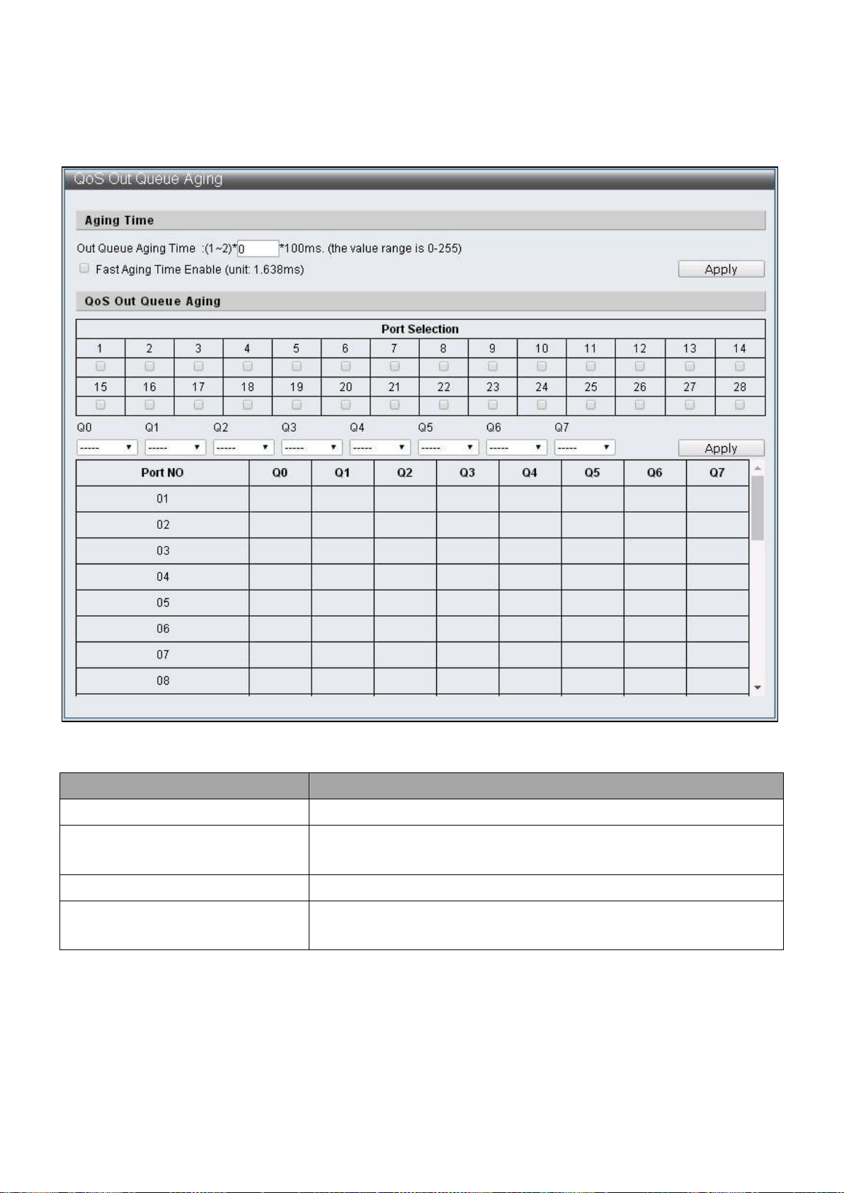
Item
Description
Out Queue Aging Time
Specify the Queue Aging Time
Fast Aging Time Enable
Specify Aging Time conversion units, change from 100ms
to 1.638ms
Port Select
Select default Ports
Q0 ~ Q7
Select the Queue with Out Queue Aging Time is enabled
by default
IV-4-3 QoS Out Queue Aging
To configure and display the QoS Out Queue Aging, click QoS Configuration > QoS Out
Queue Aging
Figure 42 – QoS Configuration > QoS Out Queue Aging
45
Page 52

Item
Description
Port Selection
Select settings Port
Mode
Mode selections of Tx,Rx or Tx&Rx
Q0 ~ Q7
Select the Queue Number mapped to each Queue by
default
IV-4-4 QoS Remap
To configure and display the QoS Remap, click QoS Configuration > QoS Remap
Figure 43 – QoS Configuration > QoS Remap
46
Page 53
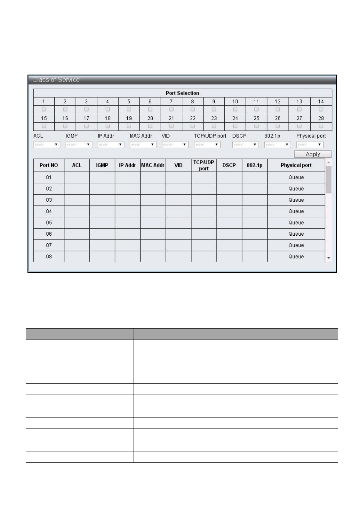
Item
Description
Port Selection
Select the Ports enabled with specific packets priority by
default
ACL
Enable / Disable ACL priority
IGMP
Enable / Disable IGMP priority
IP Addr
Enable / Disable IP Adrr (Port-MAC-IP Entry) priority
MAC Addr
Enable / Disable MAC Addr (LUT Priority) priority
VID
Enable / Disable VLAN Tag priority
TCP/UDP Port
Enable / Disable TCP/UDP Port number priority
DSCP
Enable / Disable IPv4 TOS /IPv6 DSCP priority
802.1q
Enable / Disable 802.1p priority
Physical Port
Select the priority of each Ports Q0 ~ 7
IV-4-5 Class of Service
To configure and display the Class of Service, click QoS Configuration > Class of Service
Figure 44 – QoS Configuration > Class of Service
Class of Service Priority Level:
ACL > IGMP > IP Addr > MAC Addr > VID > TCP/UDP Port > DSCP > 802.1p > Physical Port
47
Page 54

Item
Description
Earlier Edition
Select earlier edition
2005 Edition
Select 2005 edition
Exchange the priority
Edit the priority
IV-4-6 802.1q Base
To configure and display the 802.1q Base, click QoS Configuration > 802.1q Base
Figure 45 – QoS Configuration > 802.1q Base
48
Page 55

Item
Description
Priority For DSCP Not Match
Select the action when current DSCP value does not match
with DSCP List
DSCP List
Select default DSCP group
Value
Specify DSCP value
Priority
Specify Queue matching DSCP
IV-4-7 DSCP Base
To configure and display the DSCP Base, click QoS Configuration > DSCP Base
Figure 46 – QoS Configuration > DSCP Base
49
Page 56

Item
Description
Protocol
Each TCP/UDP protocol
Priority
The Queue corresponding to TCP/UDP protocol
User defined A
User defined TCP/UDP Port number
User defined B
User defined TCP/UDP Port number
User defined C
User defined TCP/UDP Port Range
User defined D
User defined TCP/UDP Port Range
IV-4-8 TCP/UDP Port Base
To configure and display the TCP/UDP Base, click QoS Configuration > TCP/UDP Port
Base
Figure 47 – QoS Configuration > TCP/UDP Base
50
Page 57
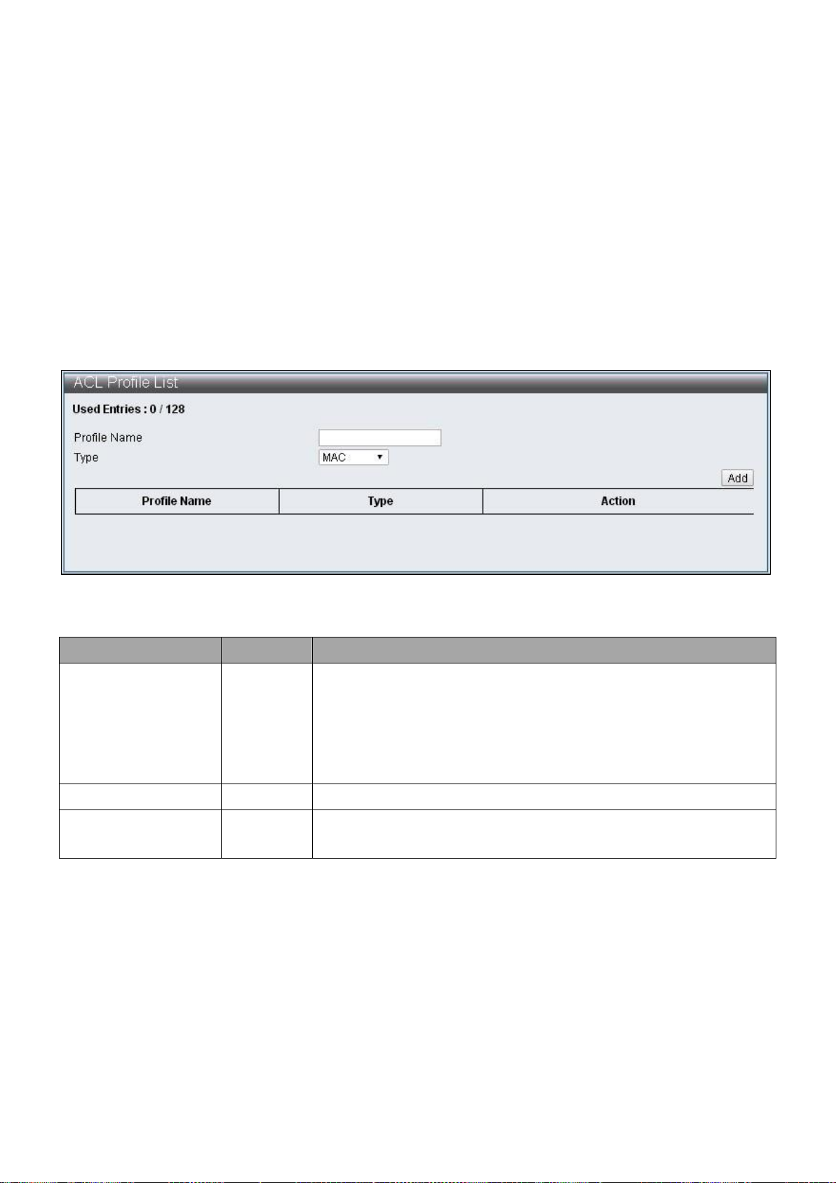
Item
Default
Description
Used Entries
0/128
Displays the number of entry used by successfully
configured rule, the maximum is 128. One rule does not
used by one entry, the number of entries used by one
rule is calculated automatically according to the
configurations
Profile Name
Name of the rules
Type
Provide types that configured by users: MAC, IP, IP_Ext,
IPv6, Advanced
IV-5 ACL Configuration
This switch provides 128 groups of Entries that can set up rules freely. Then according to
the complexity of rules set up, a rule may occupy multiple Entries.
ACL Profile List, ACL Ctag Settings, ACL Stag Settings, ACL VLAN Settings,
ACL Bandwidth Settings, ACL DSCP Settings
IV-5-1 ACL Profile List
To configure and display the ACL Profile List, click ACL Configuration > ACL Profile List
Figure 48 – ACL Configuration > ACL Profile List
The rules set up page can be entered according to following steps:
Step1:Enter Profile Name, select Type and press “Add” button.
Step2:Click “Edit” button to edit rules.
51
Page 58

Figure 49 – ACL Configuration > ACL Profile List
Figure 50 - ACL Configuration > ACL Profile List > ACL Profile Configuration - MAC
Figure 51 - ACL Configuration > ACL Profile List > ACL Profile Configuration - IP
52
Page 59

Figure 52 - ACL Configuration > ACL Profile List > ACL Profile Configuration – IP Extension
Figure 53 - ACL Configuration > ACL Profile List > ACL Profile Configuration - IPv6
53
Page 60
Item
Description
Source MAC Address
Enter Source MAC Address
Source MAC Mask
Select Source MAC Mask, then FF:FF:FF:FF:FF:FF,
FF:FF:FF:00:00:00 and FF:FF:00:00:00:00 can be selected
Destination MAC Address
Enter Destination MAC Address
Destination MAC Mask
Select Destination MAC Mask, then FF:FF:FF:FF:FF:FF,
FF:FF:FF:00:00:00 and FF:FF:00:00:00:00 can be selected
Source IP Address
Enter Source IP Address
Source IP Mask
Select Source IP Mask, then 255.255.255.255,
255.255.255.240, 255.255.255.0,255.255.240.0,
255.255.0.0,255.0.0.0 and 240.0.0.0 can be selected
Destination IP Address
Enter Destination IP Address
Destination IP Mask
Select Destination IP Mask, then 255.255.255.255,
255.255.255.240,255.255.255.0,255.255.240.0,
255.255.0.0,255.0.0.0 and 240.0.0.0 can be selected
Source Port
Enter Source Port, single value can be entered or a range
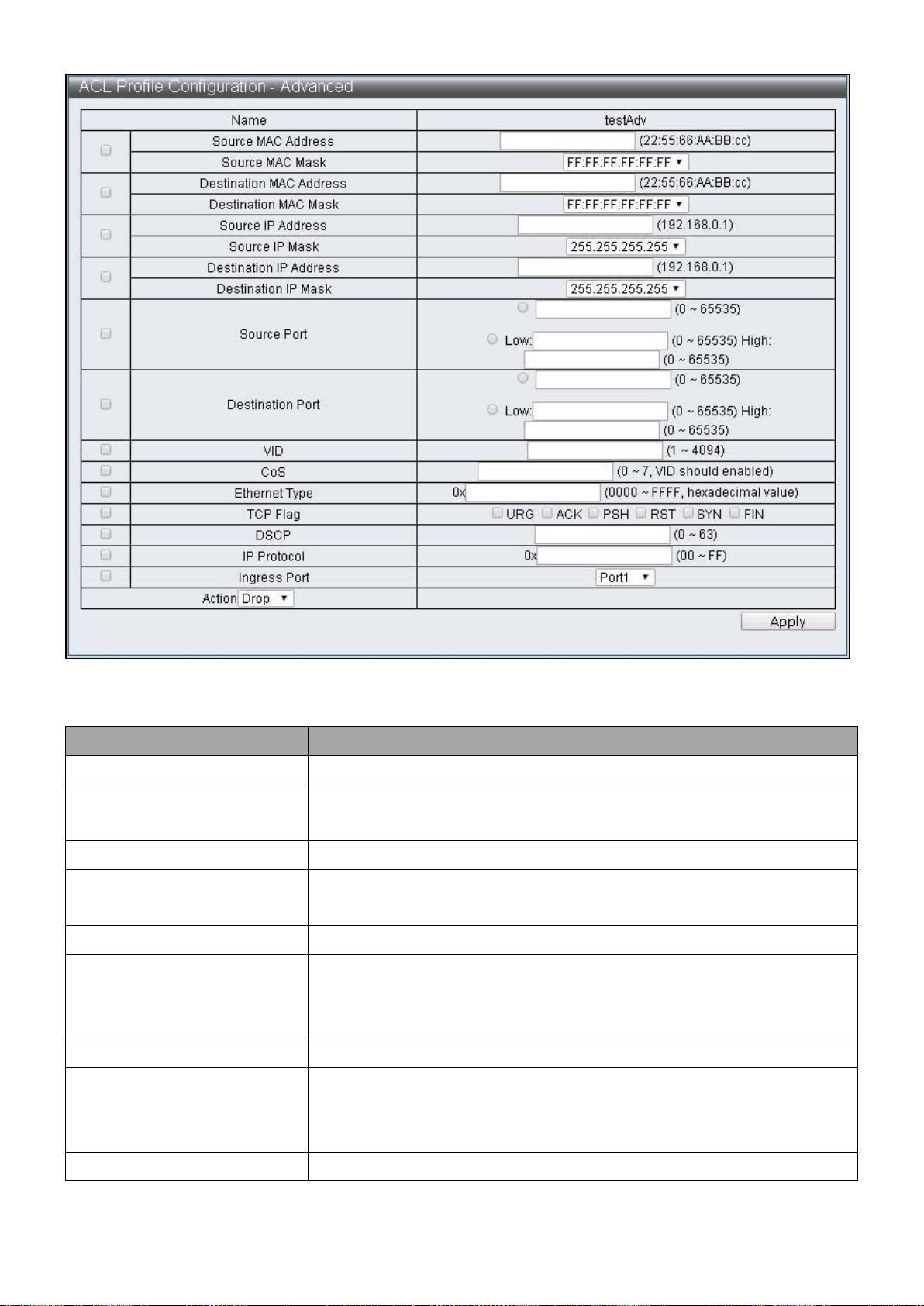
Figure 54 - ACL Configuration > ACL Profile List > ACL Profile Configuration - Advanced
54
Page 61

value can be configured
Destination Port
Enter Destination Port, single value can be entered or a range
value can be configured
VID
Enter VID, the configuration range is 1~4094
CoS
Configure CoS, it is effective only with VID settings together,
the configuration range is 0~7
Ethernet Type
Enter Ethernet Type, the configuration range is 0000~FFFF
TCP Flag
Select the TCP Flag to be checked
DSCP
Enter DSCP, the configuration range is 0~63
IP Protocol
Enter IP Protocol, the configuration range is 00~FF
Source IPv6 Address
Enter Source IPv6 Address
Source IPv6 Mask
Select Source IPv6 Mask,
FFFF:FFFF:FFFF:FFFF:FFFF:FFFF:FFFF:FFFF,FFFF:FFFF:FFFF:FFFF:
FFFF:FFFF:0000:0000,FFFF:FFFF:FFFF:0000:0000:0000:0000:00
00 and FFFF:0000:0000:0000:0000:0000:0000:0000 can be
selected
Destination IPv6 Address
Enter Destination IPv6 Address
Destination IPv6 Mask
Select Destination IPv6 Mask,
FFFF:FFFF:FFFF:FFFF:FFFF:FFFF:FFFF:FFFF,
FFFF:FFFF:FFFF:FFFF:FFFF:FFFF:0000:0000,
FFFF:FFFF:FFFF:0000:0000:0000:0000:0000 and
FFFF:0000:0000:0000:0000:0000:0000:0000 can be selected
Ingress Port
Select source Port
Action Drop
Action Type1
Action Type2
55
Page 62

Item
Description
Redirect
Specify to redirect to a Port
Priority
Specify Priority, the configuration range is 0~7
DSCP
Specify DSCP Index, edit the sent DSCP according to ACL
DSCP Settings
Bandwidth
Specify Bandwidth Index according to the value configured
by ACL Bandwidth Settings to restrict the packets traffic
Copy to CPU
Made a copy and send to CPU
PTP Enable
Specify the time when packets records is enabled
Mirror Enable
Enable Mirror function, then transmit packets to
Destination Port according to the configuration of Basic
Configuration->Port Mirror Function
Sflow Enable
Specify to enable the Sflow function
Insert Ctag
Specify Insert Ctag Index, then insert corresponding Ctag
according to ACL Ctag Settings
Ctag Vlan Enable
Enable the function of selecting ACL VLAN Settings to
transmit packets according Insert Ctag Index
Insert Stag
Specify Insert Stag Index, then insert corresponding Ctag
value according to ACL Stag Settings
Stag Vlan Enable
Enable the function of selecting ACL VLAN Settings to
transmit packets according to Insert Stag Index
Action Type3
Action Type4
56
Page 63
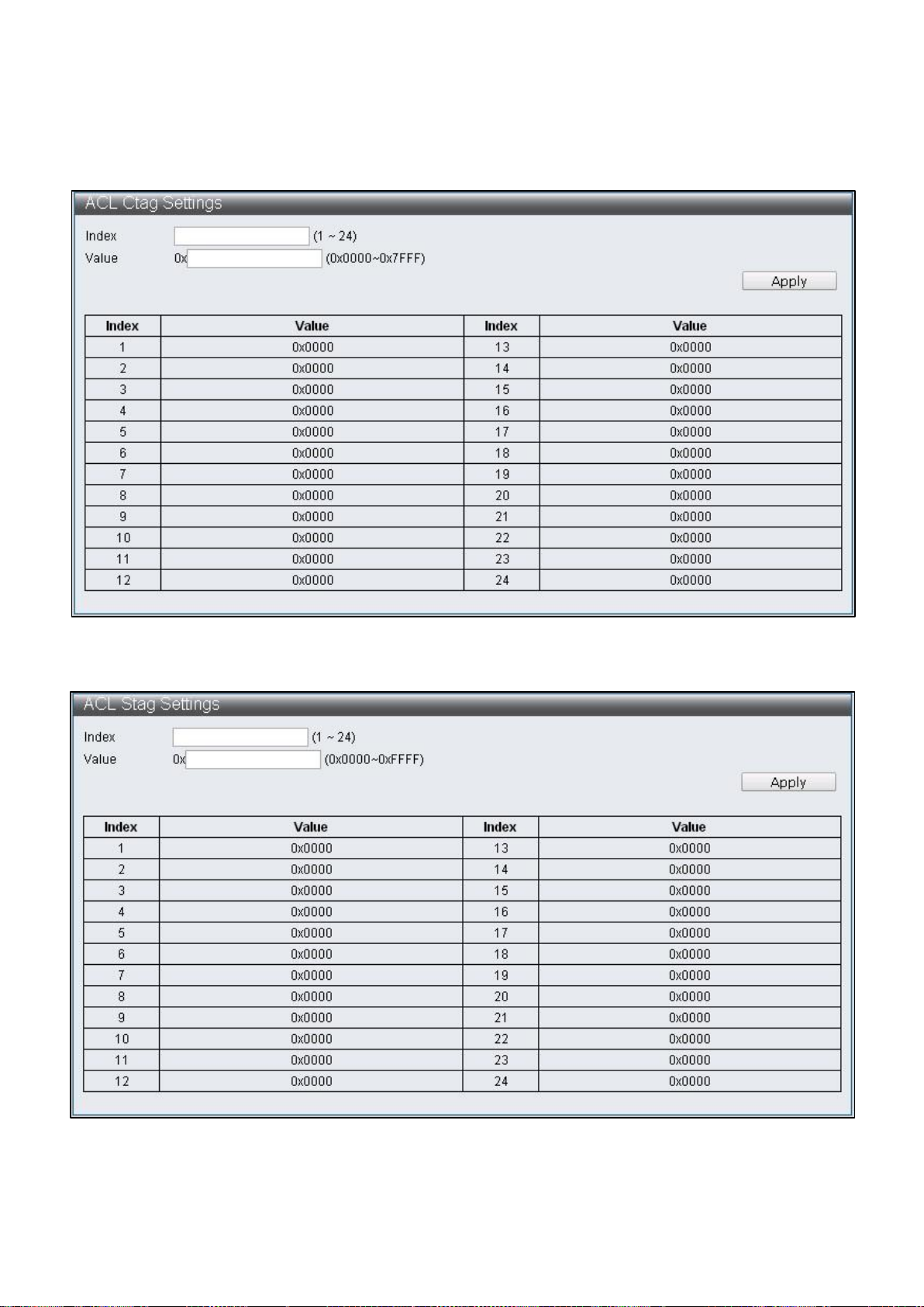
IV-5-2 ACL Ctag Settings
To configure and display the ACL Ctag Settings, click ACL Configuration > ACL Ctag
Settings
Figure 55 - ACL Configuration > ACL Ctag Settings
Figure 56 - ACL Configuration > ACL Stag Settings
57
Page 64

Figure 57 - ACL Configuration > ACL VLAN Settings
Figure 58 - ACL Configuration > ACL Bandwidth Settings
58
Page 65
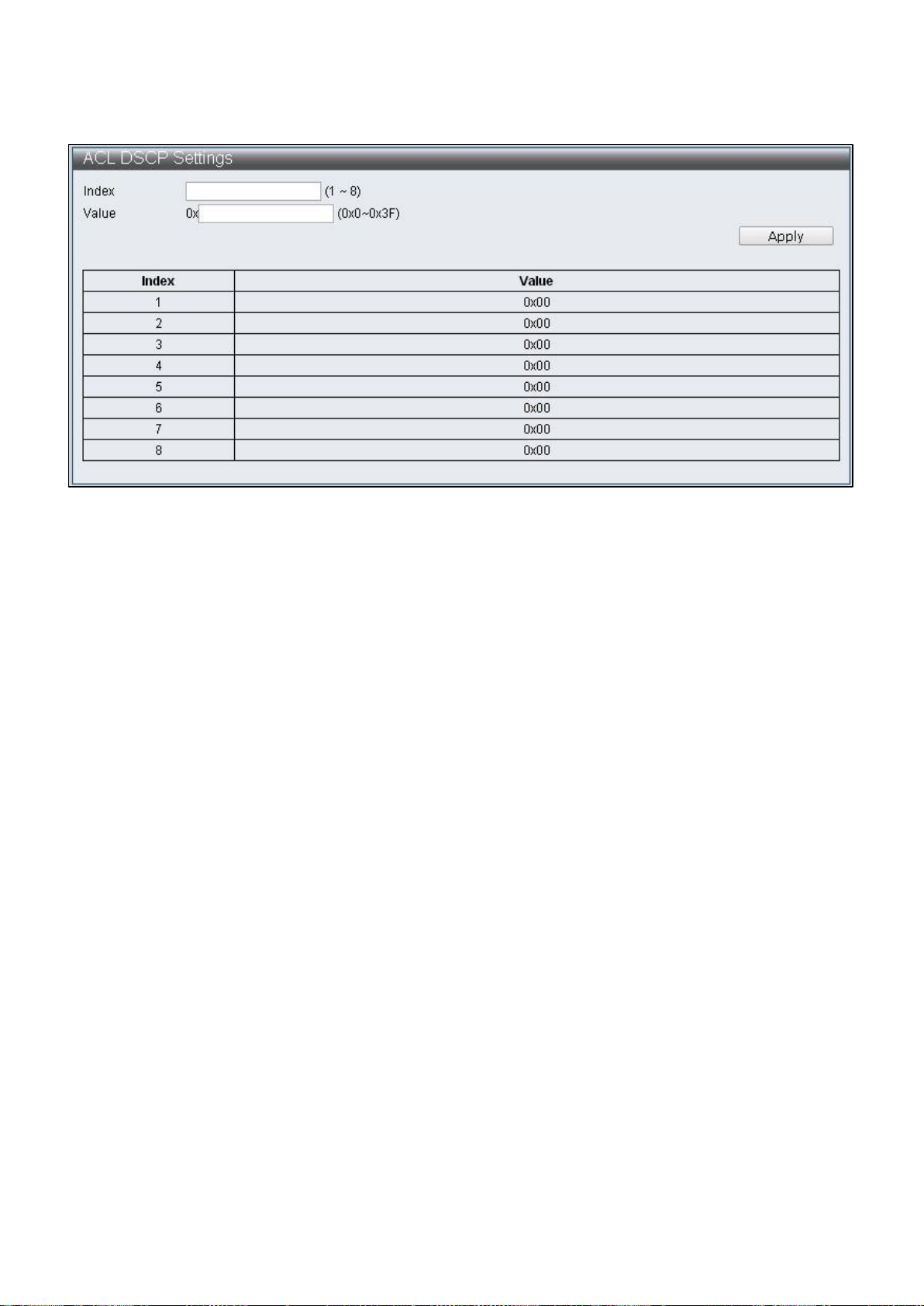
To configure and display the ACL DSCP Settings, click ACL Configuration > ACL DSCP
Settings
Figure 59 - ACL Configuration > ACL DSCP Settings
IV-6 Security
IV-6-1 Port-MAC-IP Binding
Supporting IPv4/IPv6 to achieve basic security protection and filtering through checking
the source IP address of packets. Configure each port through page to check if source IP
address, MAC address and source port are compatible, then perform further action on
matched packets through the two filtering modes.
IV-6-1-1 Port-MAC-IP Port Settings
To configure and display the Port - MAC - IP Port Settings, click Security > Port - MAC - IP
Binding > Port - MAC - IP Port Settings
59
Page 66

Item
Description
Port Selection
Select settings Ports
All
Select all Ports
Clear
Remove all Ports
Status
Enable / Disable Port-MAC-IP binding function
Max learning entry
Specify the maximum groups of dynamic binding of each Port
Recover learning entry
Enable / Disable the automatic coverage of the earliest binding
group when the dynamic binding groups reach the upper limit
Figure 60 - Security > Port - MAC – IP Binding > Port - MAC - IP Port Setting
60
Page 67

Item
Description
IPv4/IPv6
Select the default IMP Entry as IPv4 or IPv6, then enter its
IP Address in the blank cell on the right
IMP Entry Management
Select the IMP Entry to be edited in IP Table Monitor, then
click Edit for edit
IP
Match the selected IMP Entry IP Address
Check port
Enable / Disable if source Port is matched
Port
Specify the Port matched with this IP Address
Check MAC
Enable / Disable if MAC is matched
MAC
Specify the source MAC matched with IP Address
Action
Specify the matching Filter/Priority when the terms are
complied with
Priority
Specify that when Priority is enabled, the Queue matched
IMP Entry
IV-6-1-2 Port-MAC-IP Entry Setting
To configure and display the Port - MAC - IP Entry Setting, click Security > Port - MAC - IP
Binding > Port - MAC - IP Entry Settings
Figure 61 - Security > Port - MAC - IP Binding > Port - MAC - IP Entry Setting
61
Page 68

Item
Description
DHCP Snooping
Enable / Disable DHCP Snooping
ARP Inspection
Enable / Disable ARP Inspection
MAC Verification
Enable / Disable MAC Verification
IV-6-1-3 DHCP Snooping Entry Setting
To configure and display the DHCP Snooping Entry Setting, click Security > Port - MAC - IP
Binding > DHCP Snooping Entry Setting
Figure 62 - Security > Port - MAC - IP Binding > DHCP Snooping Entry Setting
IV-6-2 MAC Address Binding
To enable the security function of MAC address, packets that don’t match with MAC
address table should be configured to be discarded or ports are configured to discard
certain MAC address, port mirroring and sampling transmitted to CPU port. MAC address
not included in the MAC address table can only be effectively prevented from entering
the switch from its binding port when the port learning function is disabled. When the
port learning is enabled, MAC address included in the MAC address table can enter the
switch from its binding port, but MAC address not in the MAC address table cannot be
limited from entering the switch from any port.
To configure and display the MAC Address Binding, click Security > MAC Address Binding
62
Page 69

Item
Description
Port Selection
Select to disable port learning function
Binding Enable
Enable / Disable MAC binding
Aging Time
Specify the aging time range of MAC address binding from
1~1800000, unit: second
MAC Address
Add default MAC Address binding
Port
Select the Port binding MAC Address
MAC Entry Management
After adding the binding MAC Address, select MAC
address in the Table, click Edit to edit the content. Click
Delete to remove the setting of that record
MAC
Display the default MAC Address
port
Edit the Port binding MAC Address
Drop
When the Source MAC of packets received by Port match
with the setting, drop such packets
Figure 63 - Security > MAC Address Binding
63
Page 70

Sniffer1
When the Source MAC of packets received by Port match
with the setting, forward such packets to the Destination
Port of Port Mirror.
Sflow
Sampling transmits the matched packets to CPU ports
Priority
When the Source MAC of packets received by Port match
with the setting, save such packets into corresponding
Queue
64
Page 71

IV-7 Advanced Features
IV-7-1 Spanning Tree Protocol STP
Spanning Tree Protocol (STP) is a network protocol based on the data link layer (second
layer) of OSI model. It aims to build a loop-free logical topology for Ethernet networks.
STP prevents bridge loops and allows a network design to include backup (repetitive)
links to automatically activate back up path if an active link fails. Manual activation is
disabled and closes the demands of backup connection. Thus, STP has three functions
including: 1. Prevents broadcast storm, 2. Prevents duplicate packets, 3. Prevents MAC
address table trashing.
The STP work process is as follows: the first step is to elect a root bridge, then follow by
the bridge ID generated by combining bridge priority and MAC address. The network
bridge with smallest bridge ID will be the root bridge. Based on this, calculate the
distances from each node to the root bridge, then find the cost of redundant links. The
smallest path cost will be the communicating path (the corresponding port state will
become “forwarding”), others will be the backup paths (the corresponding port state will
become “blocking”). The communication tasks will be completed by BPDU (Bridge
Protocol Data Unit) during STP process.
BPDU
Bridge Protocol Data Unit (BPDU) is spanning tree protocol packets that send during
configured intervals and used in information exchange during network bridges.
Region (applicable to MSTP)
Switch in the same Region will only process BPDU from the same region to calculate
Topology. To check if it is in the same region, Switch will compare the three items of
spanning-tree mst configuration, these three items have to be the same to be seem as
the same Region.
Configuration Name Revision Number
VLAN and Instance map (instance 0 is CIST and communicate with STP/RSTP but cannot
be used for Region)
IV-7-1-1 STP Global Settings
To configure and display the STP Global Settings, click Advanced Features > Spanning
Tree Protocol > STP Global Settings
65
Page 72

Item
Default
Description
STP State
Enable
Enable / Disable STP state
STP Version
MSTP
Specify the STP versions used and supports STP, RSTP,
MSTP
Bridge Max Age (6-40)
20
Specify the maximum age of configuration when
this Switch is a Root Bridge, if any Bridge Port
(excluding Designated Port ) of spanning tree protocol
did not receive BPDU within this period, such Bridge
Port will start sending BPDU and build another
spanning tree protocol
Bridge Hello Time
(1-10)
2
The interval of each bridge in the STP sending BPDU
when Switch is Root Bridge
Bridge Forward Delay
(4-30)
15
Specify the time interval for all switch port
converting to Forwarding when this Switch is the
Root Bridge
Max Hops (6-40)
20
Specify the starting value of Remaining Hops when
MSTP mode is on, and the switch is the Root Bridge.
This value limit the maximum nodes BPDU can
send. Every Switch will reduce the Remaining Hops
by 1 after receiving BPDU, and no more BPDU will
be sent to the when the value reach 0.
Figure 64 - Advanced Features > Spanning Tree Protocol > STP Global Settings
66
Page 73
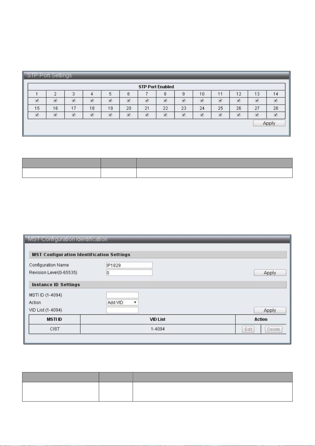
Item
Default
Description
STP Port Enabled
Enabled
Select STP enabled Port
Item
Default
Description
Configuration Name
IP1829
Specify the name of configuration, it is the only
identification of MSTI (Multiple Spanning Tree
IV-7-1-2 STP Port Settings
To configure and display the STP Port Settings, click Advanced Features > Spanning Tree
Protocol > STP Port Settings
Figure 65 – Advanced Features > Spanning Tree Protocol > STP Port Settings
IV-7-1-3 MST Configuration Identification
To configure and display the MST Configuration Identification, click Advanced Features >
Spanning Tree Protocol > MST Configuration Identification
Figure 66 – Advanced Features > Spanning Tree Protocol > MST Configuration
Identification
67
Page 74

Instance)
Revision Level(0-65535)
0
Specify version numbers to recognize if it is the same
MSTP region
MSTI ID (1-4094)
The ID code of MSTI entry to be specified
Action
Add VID
The VID List methods of MSTI to be specified
Add VID: Add VID List to this MSTI
Remove VID: Remove VID List from this MSTI
VID List (1-4094)
The VID List contents of MSTI to be changed
68
Page 75
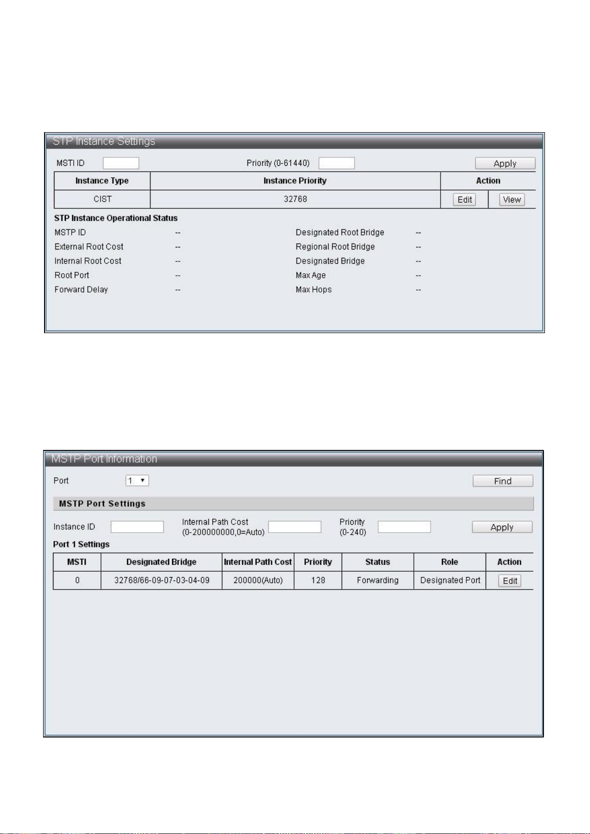
IV-7-1-4 STP Instance Settings
To configure and display the STP Instance Settings, click Advanced Features > Spanning
Tree Protocol > STP Instance Settings
Figure 67 – Advanced Features > Spanning Tree Protocol > STP Instance Settings
IV-7-1-5 MSTP Port Information
To configure and display the MSTP Port Information, click Advanced Features > Spanning
Tree Protocol > MSTP Port Information
Figure 68 – Advanced Features > Spanning Tree Protocol > MSTP Port Information
69
Page 76

Item
Default
Description
Port
1
The displaying and specified Port number
Instance ID
The ID number that needs to be specified with
MSTI entry
Internal Path Cost
(0-200000000,0=Auto)
Specify the internal path cost of this Port in MSTI
and treat this Region as an independent LAN, this
value refers to the root path cost from bridge to
the root of this network.
Priority (0-240)
Specified the priority of this Port in that MSTI
IV-7-2 Trunk & Link Aggregation
Trunk Groups are manually-configured aggregate links containing multiple ports to reach
faster network speed using specific traffic management. ES-5424P supports trunk group
of four 10/100MB and trunk group of two 1G. There are four static ports can be selected
as member in each 10/100MB trunk group, and there are two static ports can be selected
as member in each 1G trunk group. By combing two groups, then as much as eight
10/100MB members can be formed as a trunk group and join with another trunk group
of four 1G members.
To configure and display the Trunk & Link Aggregation, click Advanced Features >
Spanning Tree Protocol > Trunk & Link Aggregation
Figure 69 – Advanced Features > Spanning Tree Protocol > MSTP Port Information
70
Page 77

Item
Default
Description
Link Aggregation Algorithm
MAC Source
Link Aggregation algorithm supports Port,
MAC Source, MAC Destination , IP Source, IP
Destination, TCP/UDP Destination Port ,
TCP/UDP Source Port
Group
Group directory
Combine Group
Combine two groups
Port Select
Select group members
Status
Displays member status, “A” indicates that
function set up has been completed
State
Disable
Enable / Disable group
Trunk Type
LACP
Selection of Trunk type and supports LACP and
Static
Mode
Passive
Communication mode supports Passive and
Active
Time Out
Short
The length of Time Out, which include Short
and Long. Short refers to that packets are sent
every second, the Time Out is 3 seconds. Long
refers to that packets are sent every 30
seconds, the Time Out is 90 seconds
IV-7-3 IGMP Snooping
Internet Group Management Protocol (IGMP) Snooping
IGMP Snooping Settings
IGMP Snooping Router Ports Settings IGMP Snooping Groups
IGMP Snooping Ports
IV-7-3-1 IGMP Snooping Settings
To configure and display the IGMP Snooping Settings, click Advanced Features > IGMP
Snooping > IGMP Snooping Settings
71
Page 78

Item
Default
Description
IGMP Snooping State
Disable
Enable / Disable IGMP Snooping
Version
IGMPv3
Version selections, IGMPv1, IGMPv2 and IGMPv3
can be selected
IGMP Group Aged Out
Disable
The dynamically added Group should be
removed without receiving corresponding
packets after a period time as specified in the
GMI below
GMI
100(seconds)
Group Member Interval, dynamic Group will
inquire if there is existence of member after
specification
Router Aging Time
100(seconds)
Group Member Interval, dynamic Group will
inquire if there is existence of member after
specification
Item
Description
IGMP Snooping Static Router Ports
Static Router Ports can be specified
IGMP Snooping Dynamic Router Ports
Displays dynamic learning Router Ports
Figure 70 – Advanced Features > IGMP Snooping > IGMP Snooping Settings
IV-7-3-2 IGMP Snooping Router Ports Settings
To configure and display the IGMP Snooping Router Ports Settings, click Advanced
Features > IGMP Snooping > IGMP Snooping Router Ports Settings
Figure 71 – Advanced Features > IGMP Snooping > IGMP Snooping Router Ports Settings
72
Page 79

Item
Description
IGMP Snooping Static Group Configuration
Enable users to specify static Group and its
member port
IGMP Snooping Group Information
Displays all the currently existing Groups and
their status
Item
Description
IGMP Snooping Port Information
Displays the groups and their status of
selected Port
IV-7-3-3 IGMP Snooping Groups
To configure and display the IGMP Snooping Groups, click Advanced Features > IGMP
Snooping > IGMP Snooping Groups
Figure 72 – Advanced Features > IGMP Snooping > IGMP Snooping Groups
IV-7-3-4 IGMP Snooping Ports
To configure and display the IGMP Snooping Ports, click Advanced Features > IGMP
Snooping > IGMP Snooping Ports
Figure 73 – Advanced Features > IGMP Snooping > IGMP Snooping Ports
73
Page 80

Item
Default
Description
MLD Snooping State
Disable
Enable / Disable MLD Snooping
Version
IGMPv3
Version selections, MLDv1 and MLDv2 can be
selected
MLD Group Aged Out
Disable
The dynamically added Group should be removed
without receiving corresponding packets after a
period time as specified in the GMI below
GMI
100(seconds)
Group Member Interval, dynamic Group will inquire
if there is existence of member after specification
Router Aging Time
100(seconds)
The time of dynamic Router Port existed, if Query
packets are not received continuously, then such
dynamic Router Port will be cleared
IV-7-4 MLD Snooping
MLD Snooping
Multicast Listener Discovery (MLD) Snooping
MLD Snooping Settings
MLD Snooping Router Ports Settings MLD Snooping Groups
MLD Snooping Ports
IV-7-4-1 MLD Snooping Settings
To configure and display the MLD Snooping Settings, click Advanced Features > MLD
Snooping > MLD Snooping Settings
Figure 74 – Advanced Features > MLD Snooping > MLD Snooping Settings
74
Page 81

Item
Description
MLD Snooping Static Router Ports
Static Router Ports can be specified
MLD Snooping Dynamic Router Ports
Displays dynamic learning Router Ports
IV-7-4-2 MLD Snooping Router Ports Settings
To configure and display the MLD Snooping Router Ports Settings, click Advanced
Features > MLD Snooping > MLD Snooping Router Ports Settings
Figure 75 – Advanced Features > MLD Snooping > MLD Snooping Router Ports Settings
IV-7-4-3 MLD Snooping Groups
To configure and display the MLD Snooping Groups, click Advanced Features > MLD
Snooping > MLD Snooping Groups
Figure 76 – Advanced Features > MLD Snooping > MLD Snooping Groups
75
Page 82
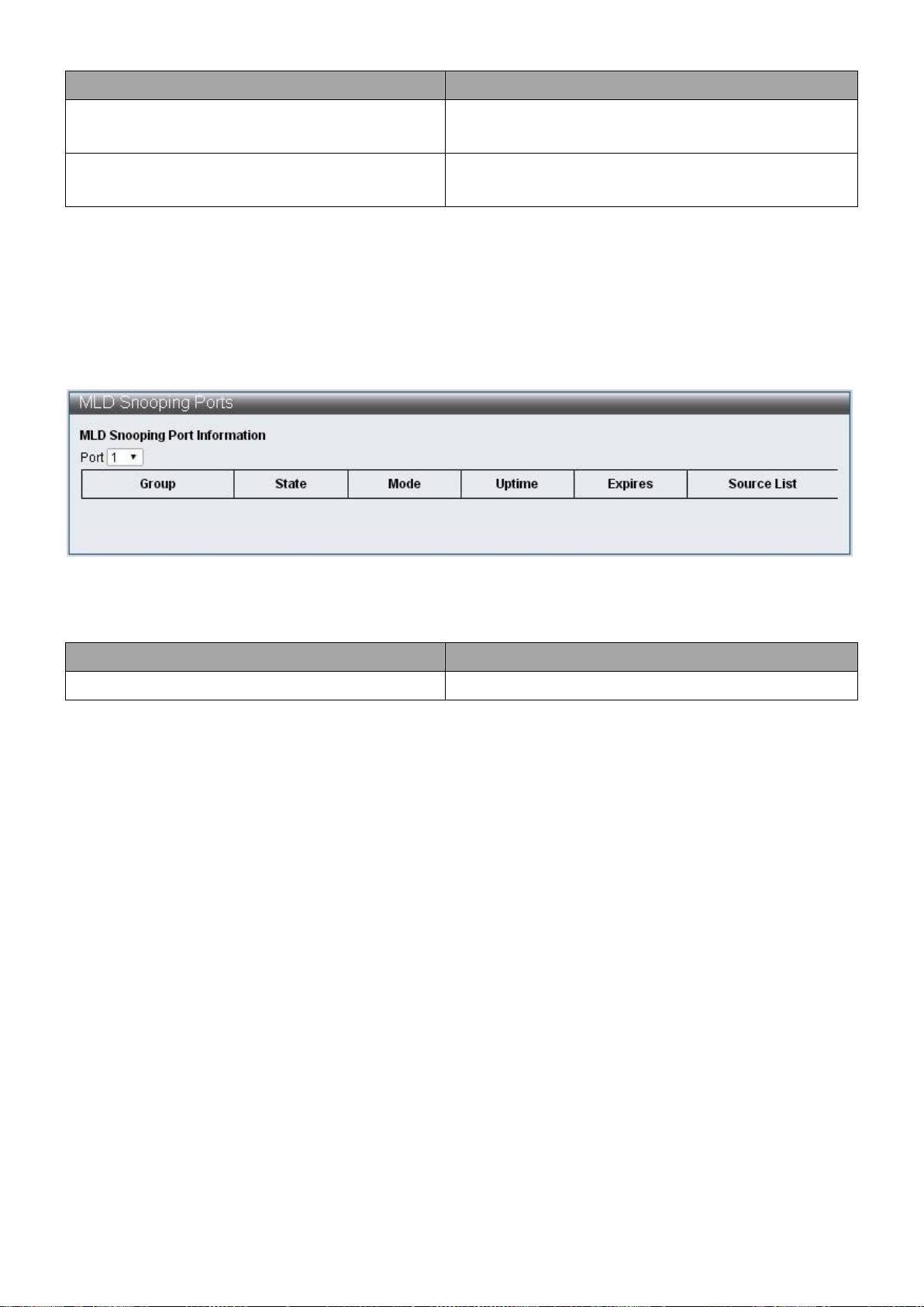
Item
Description
MLD Snooping Static Group Configuration
Enable users to specify static group and its
member port
MLD Snooping Group Information
Display the all the currently existed Groups
and their status
Item
Description
MLD Snooping Port Information
Display the group and states of selected Ports
IV-7-4-4 MLD Snooping Ports
To configure and display the MLD Snooping Ports, click Advanced Features > MLD
Snooping > MLD Snooping Ports
Figure 77 – Advanced Features > MLD Snooping > MLD Snooping Ports
76
Page 83

Item
Default
Description
DHCP relay-agent state
The switch of DHCP Relay-Agent
Hops Limit
4
The number of times DHCP packets can be
forwarded
DHCPv4 Server Setting
DHCPv4 server setting, 5 groups can be specified
DHCPv6 Server Setting
DHCPv6 server setting, 5 groups can be specified
IV-7-4-5 DHCP Relay Agent
To configure and display the DHCP Relay Agent, click Advanced Features > DHCP Relay
Agent
Figure 78 – Advanced Features >DHCP Relay Agent
77
Page 84

IV-7-5 Loop Detect
Loop Detect is able to detect the loops on the network of Switch, and then block 1 port of
2 ports that cause loop when it is detected, thus disable packets from entering Switch
through the loop and prevent the connection failure by Switch.
To configure and display the Loop Detect, click Advanced Features > Loop Detect
Figure 79 – Advanced Features > Loop Detect
78
Page 85

Item
Description
Loop Detect State
Enable/Disable Loop Detect function
LDP Interval Time
Specify the interval time of sending loop detection
packets
Block Release Time
Specify the blocked Port and its release time
LDP MAC Destination Address
Specify DA that sends loop detection packets
Loop Detect Port Enabled
Select Port with Loop Detect function enabled
Refresh
Refresh Loop Detect status
IV-7-6 GVRP
The GARP VLAN Registration Protocol (GVRP) is used to register and deregister VLAN
attributes through message exchange between each Port. GVRP use messages are Join
messages, Leave messages, and LeaveAll messages.
Join messages: When Switch receives Join messages from other devices or when it is
configured with VLAN statically, it sends Join messages to other devices.
Join messages are classified into JoinEmpty and JoinIn. JoinEmpty declares an
unregistered attribute; JoinIn declares a registered attribute.
Leave messages: When switch receives Leave message from other devices or when some
of its VLAN are deregistered statically, it sends Leave messages to other devices. Leave
messages are classified into LeaveEmpty and LeaveIn. LeaveEmpty deregisters an
unregistered attribute; LeaveIn deregisters a registered attribute.
LeaveAll messages: When the Port enabled GVRP function, LeaveAll timer is also started.
When the LeaveAll timer expires, the participant sends LeaveAll messages to other
devices. LeaveAll deregisters all attributes to delete useless attributes on the network.
GVRP timers are: Join timer, Leave timer and LeaveAll timer.
Join timer: The Join timer controls the sending of Join messages and ensures messages
can be sent to other Switch. Join timer is enabled after Join message is sent. If the JoinIn
message is not received, it sends a second Join message when the Join timer expires.
Leave timer: The Leave timer is used to control the sending of Leave messages. The Leave
timer is started after receiving a Leave or LeaveAll message. If other equipment does not
receive any Join message of the corresponding attribute before the Leave timer expires,
then such attribute is no longer in use and the Switch deregisters the attribute.
LeaveAll timer: When a Port starts GVRP function, it starts the LeaveAll timer. When the
LeaveAll timer expires, the participant sends a LeaveAll message. The LeaveAll timer will
restart after receiving LeaveAll message to prevent generation of unnecessary packets.
79
Page 86

Item
Description
GVRP Settings
Enable/Disable GVRP functions
Join Time
Specify Join timer, the minimum should not lower than 2
seconds
Leave Time
Specify Leave timer, the minimum should not lower than 2
times of Join timer
Leaveall Time
Specify Leaveall timer, the minimum should not lower
than Leave timer
Item
Description
Status
Enable/Disable Neighbor MACID functions
Send Period
Specify the send period of Neighbor Info packets
Aging Time
Specify the data removal time of each MAC ID
To configure and display the GVRP Settings, click Advanced Features > GVRP Settings
Figure 80 – Advanced Features > GVRP Settings
IV-7-7 Neighbor MACID
Neighbor MACID searches for neighboring Switch MAC ID of each Port. Then sends
Neighbor Info packets according to the configured send period, Switch will add or update
aging time of MAC ID after receiving Neighbor Info packets. The use of UDP NetCmd tool
may obtain the Switch Neighbor MAC ID information.
To configure and display the Neighbor MACID, click Advanced Features > Neighbor
MACID
Figure 81 – Advanced Features > Neighbor MACID
80
Page 87
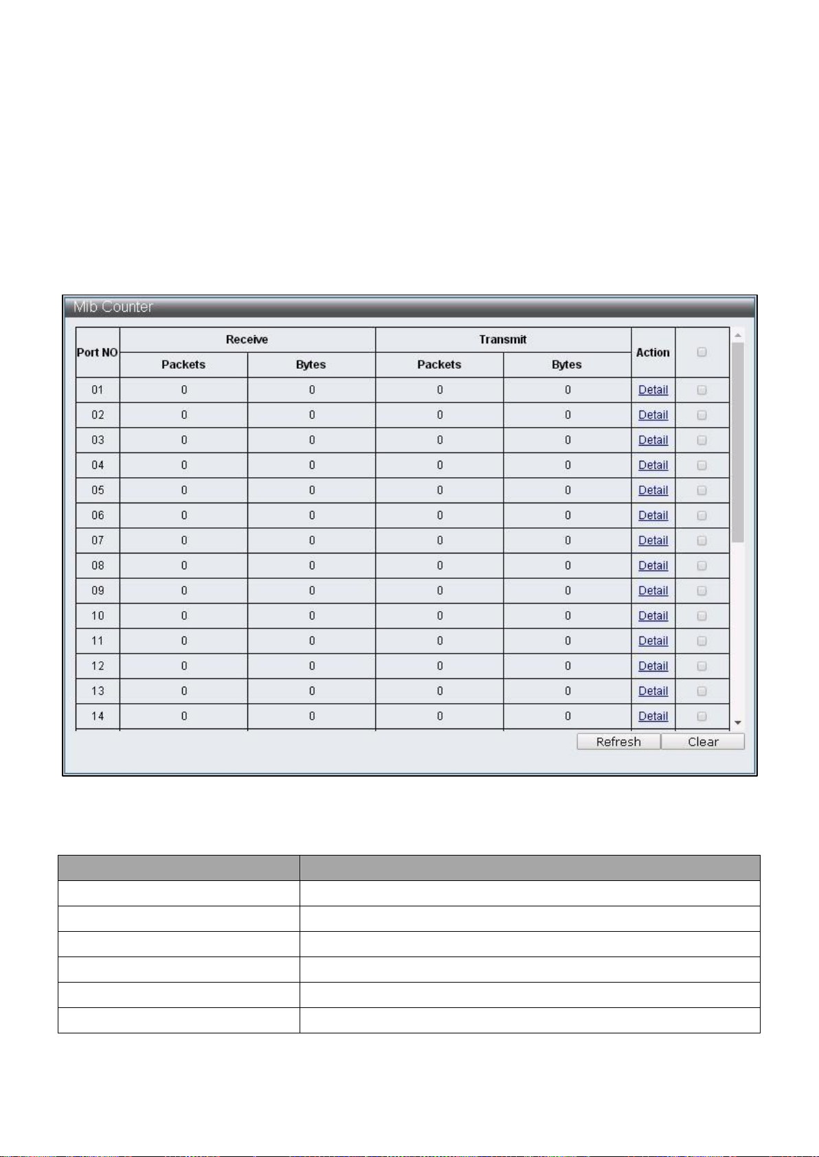
Item
Description
Port No.
Port Number
Receive
Displays data of Packets and Bytes received
Transmit
Displays data of Packets and Bytes transmitted
Action
Provide more detailed data of the Port
Refresh
Refresh the data of Ports
Clear
Clear the data of Ports
IV-8 Monitoring
IV-8-1 MIB Counter
MIB Counter is able to count the data volume received or transmitted by each Port. The
counting method of each Port can be further classified into 28 packet types received and
14 packets types transmitted.
To configure and display the MIB Counter, click Monitoring > MIB Counter
Figure 82 – Monitoring > MIB Counter
81
Page 88

Item
Description
Type
Type of packets
Receive
Display data received by different packet types
Transmit
Display data transmitted by different packet types
Refresh
Refresh the data of Ports
Clear
Clear the data of Ports
Monitoring > MIB Counter > Detail
82
Page 89

Item
Description
Port Selection
Select default Port
All
Select all the Port
Clear
Clear the selected Port
Apply
Clear the MAC Table of default Port
Refresh
Refresh MAC Table
IV-8-2 Scan MACID Lookup Table
Scan MACID Lookup Table provide MAC Address of each Port and users can remove the
MAC Address of Lookup Table.
To configure and display the Scan MACID Lookup Table, click Monitoring > Scan MACID
Lookup Table
Figure 83 – Monitoring > Scan MACID Lookup Table
83
Page 90

Item
Description
Refresh
Refresh the log
IV-8-3 Syslog
Syslog displays application log for managers.
To configure and display the Syslog, click Monitoring > Syslog
Figure 84 – Monitoring > Syslog
84
Page 91

COPYRIGHT
Copyright Edimax Technology Co., Ltd. all rights reserved. No part of this publication
may be reproduced, transmitted, transcribed, stored in a retrieval system, or translated
into any language or computer language, in any form or by any means, electronic,
mechanical, magnetic, optical, chemical, manual or otherwise, without the prior written
permission from Edimax Technology Co., Ltd.
Edimax Technology Co., Ltd. makes no representations or warranties, either expressed or
implied, with respect to the contents hereof and specifically disclaims any warranties,
merchantability, or fitness for any particular purpose. Any software described in this
manual is sold or licensed as is. Should the programs prove defective following their
purchase, the buyer (and not this company, its distributor, or its dealer) assumes the
entire cost of all necessary servicing, repair, and any incidental or consequential damages
resulting from any defect in the software. Edimax Technology Co., Ltd. reserves the right
to revise this publication and to make changes from time to time in the contents hereof
without the obligation to notify any person of such revision or changes.
The product you have purchased and the setup screen may appear slightly different from
those shown in this QIG. The software and specifications are subject to change without
notice. Please visit our website www.edimax.com for updates. All brand and product
names mentioned in this manual are trademarks and/or registered trademarks of their
respective holders.
85
Page 92

Federal Communication Commission Interference Statement
This equipment has been tested and found to comply with the limits for a Class B digital device, pursuant to Part
15 of FCC Rules. These limits are designed to provide reasonable protection against harmful interference in a
residential installation. This equipment generates, uses, and can radiate radio frequency energy and, if not
installed and used in accordance with the instructions, may cause harmful interference to radio communications.
However, there is no guarantee that interference will not occur in a particular installation. If this equipment does
cause harmful interference to radio or television reception, which can be determined by turning the equipment
off and on, the user is encouraged to try to correct the interference by one or more of the following measures:
1. Reorient or relocate the receiving antenna.
2. Increase the separation between the equipment and receiver.
3. Connect the equipment into an outlet on a circuit different from that to which the receiver is connected.
4. Consult the dealer or an experienced radio technician for help.
FCC Caution
This device and its antenna must not be co-located or operating in conjunction with any other antenna or
transmitter. This device complies with Part 15 of the FCC Rules. Operation is subject to the following two
conditions: (1) this device may not cause harmful interference, and (2) this device must accept any interference
received, including interference that may cause undesired operation. Any changes or modifications not expressly
approved by the party responsible for compliance could void the authority to operate equipment.
Federal Communications Commission (FCC) Radiation Exposure Statement
This equipment complies with FCC radiation exposure set forth for an uncontrolled environment. In order to avoid
the possibility of exceeding the FCC radio frequency exposure limits, human proximity to the antenna shall not be
less than 2.5cm (1 inch) during normal operation.
Federal Communications Commission (FCC) RF Exposure Requirements
This EUT is compliance with SAR for general population/uncontrolled exposure limits in ANSI/IEEE
C95.1-1999 and had been tested in accordance with the measurement methods and procedures specified in
OET Bulletin 65 Supplement C. The equipment version marketed in US is restricted to usage of the channels
1-11 only. This equipment is restricted to indoor use when operated in the 5.15 to 5.25 GHz frequency range.
R&TTE Compliance Statement
This equipment complies with all the requirements of DIRECTIVE 2014/30/EU OF THE EUROPEAN PARLIAMENT
AND THE COUNCIL of March 9, 1999 on radio equipment and telecommunication terminal equipment and the
mutual recognition of their conformity (R&TTE). The R&TTE Directive repeals and replaces in the directive
98/13/EEC (Telecommunications Terminal Equipment and Satellite Earth Station Equipment) As of April 8, 2000.
Safety
This equipment is designed with the utmost care for the safety of those who install and use it. However, special
attention must be paid to the dangers of electric shock and static electricity when working with electrical
equipment. All guidelines of this and of the computer manufacture must therefore be allowed at all times to
ensure the safe use of the equipment.
EU Countries Intended for Use
The ETSI version of this device is intended for home and office use in Austria, Belgium, Bulgaria, Cyprus, Czech,
Denmark, Estonia, Finland, France, Germany, Greece, Hungary, Ireland, Italy, Latvia, Lithuania, Luxembourg, Malta,
Netherlands, Poland, Portugal, Romania, Slovakia, Slovenia, Spain, Sweden, Turkey, and United Kingdom. The ETSI
version of this device is also authorized for use in EFTA member states: Iceland, Liechtenstein, Norway, and
Switzerland.
EU Countries Not Intended for Use
None
86
Page 93

EU Declaration of Conformity
English: This equipment is in compliance with the essential requirements and other relevant
provisions of Directive 2014/30/EU.
Français: Cet équipement est conforme aux exigences essentielles et autres dispositions de la
directive 2014/30/EU.
Čeština: Toto zařízení je v souladu se základními požadavky a ostatními příslušnými ustanoveními
směrnic 2014/30/EU.
Polski: Urządzenie jest zgodne z ogólnymi wymaganiami oraz szczególnymi warunkami
określonymi Dyrektywą UE 2014/30/EU.
Română: Acest echipament este în conformitate cu cerinţele esenţiale şi alte prevederi relevante ale
Directivei 2014/30/EU.
Русский: Это оборудование соответствует основным требованиям и положениям Директивы
2014/30/EU.
Magyar: Ez a berendezés megfelel az alapvető követelményeknek és más vonatkozó irányelveknek
(2014/30/EU).
Türkçe: Bu cihaz 2014/30/EU. direktifleri zorunlu istekler ve diğer hükümlerle ile uyumludur.
Українська: Обладнання відповідає вимогам і умовам директиви 2014/30/EU.
Slovenčina: Toto zariadenie spĺňa základné požiadavky a ďalšie príslušné ustanovenia smerníc
2014/30/EU.
Deutsch: Dieses Gerät erfüllt die Voraussetzungen gemäß den Richtlinien 2014/30/EU.
Español: El presente equipo cumple los requisitos esenciales de la Directiva 2014/30/EU.
Italiano: Questo apparecchio è conforme ai requisiti essenziali e alle altre disposizioni applicabili
della Direttiva 2014/30/EU.
Nederlands: Dit apparaat voldoet aan de essentiële eisen en andere van toepassing zijnde bepalingen
van richtlijn 2014/30/EU.
Português: Este equipamento cumpre os requesitos essênciais da Directiva 2014/30/EU.
Norsk: Dette utstyret er i samsvar med de viktigste kravene og andre relevante regler i Direktiv
2014/30/EU.
Svenska: Denna utrustning är i överensstämmelse med de väsentliga kraven och övriga relevanta
bestämmelser i direktiv 2014/30/EU.
Dansk: Dette udstyr er i overensstemmelse med de væ sentligste krav og andre relevante
forordninger i direktiv 2014/30/EU.
suomen kieli: Tämä laite täyttää direktiivien 2014/30/EU. oleelliset vaatimukset ja muut asiaankuuluvat
määräykset.
-----------------------------------------------------------------------------------------------------------------------
WEEE Directive & Product Disposal
At the end of its serviceable life, this product should not be treated as household or general waste. It
should be handed over to the applicable collection point for the recycling of electrical and electronic
equipment, or returned to the supplier for disposal.
87
Page 94

Declaration of Conformity
We, Edimax Technology Co., Ltd., declare under our sole responsibility, that the
equipment described below complies with the requirements of the European R&TTE
directives.
Equipment:
24-port FE Smart Switch + 4 Combo GbE Ports w/ 24 PoE+ ports
Model No.:
ES-5424P
The following European standards for essential requirements have been followed:
Directives 2014/30/EU
EMC
:
EN 55032:2015
EN 61000-3-2:2014 Class A
EN 61000-3-3:2013
EN 55035:2017
Safety (LVD)
:
EN 60950-1:2006 + A11:2009 + A1:2010 + A12:2011+A2:2013
Date of Signature:
Aug., 2018
Signature:
Printed Name:
Albert Chang
Title:
Director
Edimax Technology Co., Ltd.
Edimax Technology Europe B.V.
Fijenhof 2,
5652 AE Eindhoven,
The Netherlands
a company of :
Edimax Technology Co., Ltd.
No. 278, Xinhu 1st Rd.,
Neihu Dist., Taipei City,
Taiwan
Signature:
Printed Name:
Vivian Ma
Title:
Director
Edimax Technology Europe B.V.
88
Page 95

Notice According to GNU General Public License Version 2
This product includes software that is subject to the GNU General Public License version 2. The program is free software and
distributed without any warranty of the author. We offer, valid for at least three years, to give you, for a charge no more
than the costs of physically performing source distribution, a complete machine-readable copy of the corresponding source
code.
Das Produkt beinhaltet Software, die den Bedingungen der GNU/GPL-Version 2 unterliegt. Das Programm ist eine sog. „Free
Software“, der Autor stellt das Programm ohne irgendeine Gewährleistungen zur Verfügung. Wir bieten Ihnen für einen
Zeitraum von drei Jahren an, eine vollständige maschinenlesbare Kopie des Quelltextes der Programme zur Verfügung zu
stellen – zu nicht höheren Kosten als denen, die durch den physikalischen Kopiervorgang anfallen.
GNU GENERAL PUBLIC LICENSE
Version 2, June 1991
Copyright (C) 1989, 1991 Free Software Foundation, Inc. 51 Franklin Street, Fifth Floor, Boston, MA 02110-1301, USA
Everyone is permitted to copy and distribute verbatim copies of this license document, but changing it is not allowed.
Preamble
The licenses for most software are designed to take away your freedom to share and change it. By contrast, the GNU General
Public License is intended to guarantee your freedom to share and change free software--to make sure the software is free
for all its users. This General Public License applies to most of the Free Software Foundation’s software and to any other
program whose authors commit to using it. (Some other Free Software Foundation software is covered by the GNU Lesser
General Public License instead.) You can apply it to your programs, too.
When we speak of free software, we are referring to freedom, not price. Our General Public Licenses are designed to make
sure that you have the freedom to distribute copies of free software (and charge for this service if you wish), that you receive
source code or can get it if you want it, that you can change the software or use pieces of it in new free programs; an d that
you know you can do these things.
To protect your rights, we need to make restrictions that forbid anyone to deny you these rights or to ask you to surrender
the rights. These restrictions translate to certain responsibilities for you if you distribute copies of the software, or if you
modify it.
For example, if you distribute copies of such a program, whether gratis or for a fee, you must give the recipients all the rights
that you have. You must make sure that they, too, receive or can get the source code. And you must show them these terms
so they know their rights.
We protect your rights with two steps: (1) copyright the software, and (2) offer you this license which gives you legal
permission to copy, distribute and/or modify the software.
Also, for each author’s protection and ours, we want to make certain that everyone understands that there is no warranty for
this free software. If the software is modified by someone else and passed on, we want its recipients to know that what they
have is not the original, so that any problems introduced by others will not reflect on the original authors’ reputations.
Finally, any free program is threatened constantly by software patents. We wish to avoid the danger that redistributors of a
free program will individually obtain patent licenses, in effect making the program proprietary. To prevent this, we have
made it clear that any patent must be licensed for everyone’s free use or not licensed at all.
The precise terms and conditions for copying, distribution and modification follow.
TERMS AND CONDITIONS FOR COPYING, DISTRIBUTION AND MODIFICATION
0. This License applies to any program or other work which contains a notice placed by the copyright holder saying it may be
distributed under the terms of this General Public License. The ‘“Program’“, below, refers to any such program or work, and a
‘“work based on the Program’“ means either the Program or any derivative work under copyright law: that is to say, a work
containing the Program or a portion of it, either verbatim or with modifications and/or translated into another language.
(Hereinafter, translation is included without limitation in the term ‘“modification’“.) Each licensee is addressed as ‘“you’“.
Activities other than copying, distribution and modification are not covered by this License; they are outside its scope. The
act of running the Program is not restricted, and the output from the Program is covered only if its contents constitute a
work based on the Program (independent of having been made by running the Program). Whether that is true depends on
what the Program does.
1. You may copy and distribute verbatim copies of the Program’s source code as you receive it, in any medium, provided that
you conspicuously and appropriately publish on each copy an appropriate copyright notice and disclaimer of warranty; keep
89
Page 96

intact all the notices that refer to this License and to the absence of any warranty; and give any other recipients of the
Program a copy of this License along with the Program.
You may charge a fee for the physical act of transferring a copy, and you may at your option offer warranty protection in
exchange for a fee.
2. You may modify your copy or copies of the Program or any portion of it, thus forming a work based on the Program, and
copy and distribute such modifications or work under the terms of Section 1 above, provided that you also meet all of these
conditions:
a) You must cause the modified files to carry prominent notices stating that you changed the files and the date of any
change.
b) You must cause any work that you distribute or publish, that in whole or in part contains or is derived from the
Program or any part thereof, to be licensed as a whole at no charge to all third parties under the terms of this
License.
c) If the modified program normally reads commands interactively when run, you must cause it, when started
running for such interactive use in the most ordinary way, to print or display an announcement including an
appropriate copyright notice and a notice that there is no warranty (or else, saying that you provide a warranty)
and that users may redistribute the program under these conditions, and telling the user how to view a copy of
this License. (Exception: if the Program itself is interactive but does not normally print such an announcement,
your work based on the Program is not required to print an announcement.)
These requirements apply to the modified work as a whole. If identifiable sections of that work are not derived from the
Program, and can be reasonably considered independent and separate works in themselves, then this License, and its terms,
do not apply to those sections when you distribute them as separate works. But when you distribute the same sections as
part of a whole which is a work based on the Program, the distribution of the whole must be on the terms of this License,
whose permissions for other licensees extend to the entire whole, and thus to each and every part regardless of who wrote
it.
Thus, it is not the intent of this section to claim rights or contest your rights to work written entirely by you; rather, th e intent
is to exercise the right to control the distribution of derivative or collective works based on the Program.
In addition, mere aggregation of another work not based on the Program with the Program (or with a work based on the
Program) on a volume of a storage or distribution medium does not bring the other work under the scope of this License.
3. You may copy and distribute the Program (or a work based on it, under Section 2) in object code or executable form under
the terms of Sections 1 and 2 above provided that you also do one of the following:
a) Accompany it with the complete corresponding machine-readable source code, which must be distributed under
the terms of Sections 1 and 2 above on a medium customarily used for software interchange; or,
b) Accompany it with a written offer, valid for at least three years, to give any third party, for a charge no more than
your cost of physically performing source distribution, a complete machine-readable copy of the corresponding
source code, to be distributed under the terms of Sections 1 and 2 above on a medium customarily used for
software interchange; or,
c) Accompany it with the information you received as to the offer to distribute corresponding source code. (This
alternative is allowed only for noncommercial distribution and only if you received the program in object code or
executable form with such an offer, in accord with Subsection b above.)
The source code for a work means the preferred form of the work for making modifications to it. For an executable work,
complete source code means all the source code for all modules it contains, plus any associated interface definition files, plus
the scripts used to control compilation and installation of the executable. However, as a special exception, the source code
distributed need not include anything that is normally distributed (in either source or binary form) with the major
components (compiler, kernel, and so on) of the operating system on which the executable runs, unless that component
itself accompanies the executable.
If distribution of executable or object code is made by offering access to copy from a designated place, then offering
equivalent access to copy the source code from the same place counts as distribution of the source code, even though third
parties are not compelled to copy the source along with the object code.
4. You may not copy, modify, sublicense, or distribute the Program except as expressly provided under this License. Any
attempt otherwise to copy, modify, sublicense or distribute the Program is void, and will automatically terminate your rights
under this License. However, parties who have received copies, or rights, from you under this License will not have their
licenses terminated so long as such parties remain in full compliance.
5. You are not required to accept this License, since you have not signed it. However, nothing else grants you permission to
modify or distribute the Program or its derivative works. These actions are prohibited by law if you do not accept this License.
90
Page 97

Therefore, by modifying or distributing the Program (or any work based on the Program), you indicate your acceptance of
this License to do so, and all its terms and conditions for copying, distributing or modifying the Program or works based on it.
6. Each time you redistribute the Program (or any work based on the Program), the recipient automatically receives a license
from the original licensor to copy, distribute or modify the Program subject to these terms and conditions. You may not
impose any further restrictions on the recipients’ exercise of the rights granted herein. You are not responsible for enforcing
compliance by third parties to this License.
7. If, as a consequence of a court judgment or allegation of patent infringement or for any other reason (not limited to patent
issues), conditions are imposed on you (whether by court order, agreement or otherwise) that contradict the conditions of
this License, they do not excuse you from the conditions of this License. If you cannot distribute so as to satisfy
simultaneously your obligations under this License and any other pertinent obligations, then as a consequence you may not
distribute the Program at all. For example, if a patent license would not permit royalty-free redistribution of the Program by
all those who receive copies directly or indirectly through you, then the only way you could satisfy both it and this License
would be to refrain entirely from distribution of the Program.
If any portion of this section is held invalid or unenforceable under any particular circumstance, the balance of the section is
intended to apply and the section as a whole is intended to apply in other circumstances.
It is not the purpose of this section to induce you to infringe any patents or other property right claims or to contest validity
of any such claims; this section has the sole purpose of protecting the integrity of the free software distribution system,
which is implemented by public license practices. Many people have made generous contributions to the wide range of
software distributed through that system in reliance on consistent application of that system; it is up to the author/donor to
decide if he or she is willing to distribute software through any other system and a licensee cannot impose that ch oice.
This section is intended to make thoroughly clear what is believed to be a consequence of the rest of this License.
8. If the distribution and/or use of the Program is restricted in certain countries either by patents or by copyrighted interfaces,
the original copyright holder who places the Program under this License may add an explicit geographical distribution
limitation excluding those countries, so that distribution is permitted only in or among countries not thus excluded. In such
case, this License incorporates the limitation as if written in the body of this License.
9. The Free Software Foundation may publish revised and/or new versions of the General Public License from time to time.
Such new versions will be similar in spirit to the present version, but may differ in detail to address new problems or
concerns.
Each version is given a distinguishing version number. If the Program specifies a version number of this License which applies
to it and ‘“any later version’“, you have the option of following the terms and conditions either of that version or of any later
version published by the Free Software Foundation. If the Program does not specify a version number of this License, you
may choose any version ever published by the Free Software Foundation.
10. If you wish to incorporate parts of the Program into other free programs whose distribution conditions are different,
write to the author to ask for permission. For software which is copyrighted by the Free Software Foundation, write to the
Free Software Foundation; we sometimes make exceptions for this. Our decision will be guided by the two goals of
preserving the free status of all derivatives of our free software and of promoting the sharing and reuse of software
generally.
NO WARRANTY
11. BECAUSE THE PROGRAM IS LICENSED FREE OF CHARGE, THERE IS NO WARRANTY FOR THE PROGRAM, TO THE EXTENT
PERMITTED BY APPLICABLE LAW. EXCEPT WHEN OTHERWISE STATED IN WRITING THE COPYRIGHT HOLDERS AND/OR OTHER
PARTIES PROVIDE THE PROGRAM ‘“AS IS’“ WITHOUT WARRANTY OF ANY KIND, EITHER EXPRESSED OR IMPLIED, INCLUDING,
BUT NOT LIMITED TO, THE IMPLIED WARRANTIES OF MERCHANTABILITY AND FITNESS FOR A PARTICULAR PURPOSE. THE
ENTIRE RISK AS TO THE QUALITY AND PERFORMANCE OF THE PROGRAM IS WITH YOU. SHOULD THE PROGRAM PROVE
DEFECTIVE, YOU ASSUME THE COST OF ALL NECESSARY SERVICING, REPAIR OR CORRECTION.
12. IN NO EVENT UNLESS REQUIRED BY APPLICABLE LAW OR AGREED TO IN WRITING WILL ANY COPYRIGHT HOLDER, OR ANY
OTHER PARTY WHO MAY MODIFY AND/OR REDISTRIBUTE THE PROGRAM AS PERMITTED ABOVE, BE LIABLE TO YOU FOR
DAMAGES, INCLUDING ANY GENERAL, SPECIAL, INCIDENTAL OR CONSEQUENTIAL DAMAGES ARISING OUT OF THE USE OR
INABILITY TO USE THE PROGRAM (INCLUDING BUT NOT LIMITED TO LOSS OF DATA OR DATA BEING RENDERED INACCURATE
OR LOSSES SUSTAINED BY YOU OR THIRD PARTIES OR A FAILURE OF THE PROGRAM TO OPERATE WITH ANY OTHER
PROGRAMS), EVEN IF SUCH HOLDER OR OTHER PARTY HAS BEEN ADVISED OF THE POSSIBILITY OF SUCH DAMAGES.
91
 Loading...