

Page 1

IIC
C--
7
7
0
0
0
0
0
0
PPaann//TTiilltt IIPP SSuurrvveeiillllaannccee CCaam
meerraa
Pan/Tilt Remote Control
with Audio & Night Vision
User’s Manual
Page 2

`
IC-7000 CAM User’s Guide
PPaann//TTiilltt IIPP SSuurrvveeiillllaannccee CCaammeerra
a
IC-7000 USER’S GUIDE PAGE 2/62 Rev. PV1.0
--------------------------------------------TABLE OF CONTENTS--------------------------------------------
1. OVERVIEW.............................................................................................................................. 5
1.1 PRODUCT DESCRIPTION ............................................................................................................. 5
1.2 PRODUCT FEATURE.................................................................................................................... 5
1.3 PRODUCT SPECIFICATION ........................................................................................................... 5
1.4 PACKAGE CONTENTS.................................................................................................................. 6
1.5 SYSTEM REQUIREMENT .............................................................................................................. 6
1.6 INTRODUCTION OF IC-7000 EXTERIOR FUNCTIONS ...................................................................... 7
1.7 INTRODUCTION OF TV_OUT FUNCTION....................................................................................... 8
1.8 BASIC SET-UP PROCEDURES .................................................................................................... 9
2. UTILITIES AND TOOLS.............................................................................................................. 9
2.1 CAM_EZ SEARCH .....................................................................................................................9
2.2 USE IP-CAM AND TEST THE FUNCTIONALITY FOR THE FIRST TIME .............................................. 10
2.3 NETWORK SETUP.....................................................................................................................12
2.4 SETTING THE WAY HOW IP-CAM OBTAIN IP-ADDRESS...............................................................12
2.5 INSTALLATION PROCEDURE FOR NETWORK ENVIRONMENT WITH RESIDENTIAL ROUTER ...............25
2.6 WORK-AROUND FOR AUDIO PROBLEM WITH RESIDENTIAL ROUTER ............................................. 27
3. GETTING STARTED................................................................................................................ 29
3.1 SYSTEM LOGIN......................................................................................................................... 29
3.2 LIVEVIEW................................................................................................................................. 30
3.3 TAKE A SHOT............................................................................................................................ 33
4. ADVANCED FUNCTION OF LIVEVIEW ...................................................................................... 34
4.1 IMAGE ADJUSTMENT ................................................................................................................. 34
4.2 AVI RECORD SETUP ................................................................................................................. 35
4.3 IMAGE ENLARGEMENT ..............................................................................................................35
4.4 MOTION DETECTION SETUP ...................................................................................................... 36
4.5 MOTOR CONTROL .................................................................................................................... 37
5. ADVANCED APPLICATION ...................................................................................................... 37
5.1 IMAGE SETUP........................................................................................................................... 37
5.2 CAPTURE VIEW ........................................................................................................................38
5.3 EVENT TRIGGER....................................................................................................................... 39
5.4 NETWORK SETUP.....................................................................................................................40
5.5 SERVER SETUP........................................................................................................................42
5.6 ADMINISTRATION SETUP ...........................................................................................................44
5.7 SOFTWARE UPDATE ................................................................................................................. 46
Page 3

`
IC-7000 CAM User’s Guide
PPaann//TTiilltt IIPP SSuurrvveeiillllaannccee CCaammeerra
a
IC-7000 USER’S GUIDE PAGE 3/62 Rev. PV1.0
APPENDIX ................................................................................................................................49
APPENDIX A. USING A PPPOE DIALUP CONNECTION AND DDNS WITH THE IC-7000 EZ IPCAM (USING A
HUB ) ............................................................................................................................................... 49
APPENDIX B. FAQ: ........................................................................................................................... 58
Page 4

`
IC-7000 CAM User’s Guide
PPaann//TTiilltt IIPP SSuurrvveeiillllaannccee CCaammeerra
a
IC-7000 USER’S GUIDE PAGE 4/62 Rev. PV1.0
Copyright© by Edimax Technology Co, LTD. all rights reserved. No part of this
publication may be reproduced, transmitted, transcribed, stored in a retrieval system,
or translated into any language or computer language, in any form or by any means,
electronic, mechanical, magnetic,optical, chemical, manual or otherwise, without the
prior written permission of this company
This company makes no representations or warranties, either expressed or implied,
with respect to the contents hereof and specifically disclaims any warranties,
merchantability or fitness for any particular purpose. Any software described in this
manual is sold or licensed "as is". Should the programs prove defective following their
purchase, the buyer (and not this company, its distributor, or its dealer) assumes the
entire cost of all necessary servicing, repair, and any incidental or consequential
damages resulting from any defect in the software. Further, this company reserves the
right to revise this publication and to make changes from time to time in the contents
hereof without obligation to notify any person of such revision or changes.
The product you have purchased and the setup screen may appear slightly different
from those shown in this QIG. For more detailed information about this product, please
refer to the User's Manual on the CD-ROM.The software and specifications subject to
change without notice. Please visit our web site www.edimax.com.tw for the update. All
right reserved including all brand and product names mentioned in this manual are
trademarks and/or registeredtrademarks of their respective holders.
Linux Open Source Code
Certain Edimax products include software code developed by third parties,
including software code subject to the GNU General Public License ("GPL") or
GNU Lesser General Public License ("LGPL"). Please see the GNU
(www.gnu.org) and LPGL (www.gnu.org) Web sites to view the terms of each
license.
The GPL Code and LGPL Code used in Edimax products are distributed without
any warranty and are subject to the copyrights of their authors. For details, see
the GPL Code and LGPL Code licenses. You can download the firmware-files at
http://www.edimax.com.tw under "Download" page.
※ The product you have purchased and the setup screen may appear slightly
different from those shown in this QIG. For more detailed information about this
product, please refer to the User's Manual on the CD-ROM.
※ Software and specifications subject to change without notice. Please visit our web
site for the update.
※ All rights reserved. Trademarks or registered trademarks are the property of their
respective
Page 5

`
IC-7000 CAM User’s Guide
PPaann//TTiilltt IIPP SSuurrvveeiillllaannccee CCaammeerra
a
IC-7000 USER’S GUIDE PAGE 5/62 Rev. PV1.0
1. OVERVIEW
1.1 PRODUCT DESCRIPTION
IC-7000 is an effective and easy-to-use IP Camera for remote monitoring. The setup
procedure required for this device is very simple. Built-in Web server allows you to use
web browser (e.g., Microsoft IE) through LAN or internet in any time and any place. Type
the IP address of the IP-CAM camera on the address bar of web browser to carry out the
works of remote image monitoring and administration. Also, the user can control the
motor of the camera to change the direction of camera over internet, and obtain the
real-time image of the monitored location.
In addition, the camera supports many network protocols such as PPPoE, DHCP,
STATIC IP, DDNS, SMTP, FTP and NTP with high-performance SDRAM control and
memory card access. The built-in TV-out decoding/coding feature can display monitored
image on TV screen (NTSC or PAL TV) in families with combining fast Motion Detection
and SD Expansion Card in hardware. Moreover, IC-7000 is equipped with IR LED, so it is
capable to work in environments without light. Besides, this device also has the function
of video recording and real-time photographing. To a family, such remote monitoring can
reach professional security and have great fun.
1.2 PRODUCT FEATURE
¾ Use standard web browser to monitor, record, and take shot remotely.
¾ Maximum image resolution: 640x480, full-screen display.
¾ View images from multiple camera in a single web browser.
¾ Allow on-line image viewing remotely for multi-user simultaneously
¾ Motion-triggered capture.
¾ Remote real-time video recoding, images can be stored on FTP, SD Card, PC, and send by
E-mail.
¾ Support virtual IP and port switch in IP DSLAM.
¾ Support multiple communication protocols: TCP/IP, DHCP, SMTP, FTP, PPPoE, DDNS,
¾ Password-protected web access control.
¾ Standard RJ-45 network connector, supports 10/100 Mbps Ethernet.
1.3 PRODUCT SPECIFICATION
Image Size: 160x120、320x240、640x480 (Selectable)
Image Quality: Fine、Normal、Basic (Selectable)
Video Frequency: 50 Hz for PAL、60 Hz for NTSC
Image Compression Format : M-JPEG
Focal Distance Range : From 30mm to infinity (Adjustable)
Digital Zoom : 4X
Video Recording : Video Frame rate setting : auto; 1, 3, 5, 10, fps (Selectable)
Motion-triggered image capture, image can be sent to FTP, E-Mail, SD Card and PC
Supports TCP/IP, SMTP, FTP, PPPoE, DHCP Protocol.
Page 6

`
IC-7000 CAM User’s Guide
PPaann//TTiilltt IIPP SSuurrvveeiillllaannccee CCaammeerra
a
IC-7000 USER’S GUIDE PAGE 6/62 Rev. PV1.0
Obtain IP address from DHCP server, or manually setting. (Also supports PPPoE
protocol when used with DSL lines).
Build-in web server.
Remote image capture (JPG format), remote video recording (AVI format).
Microphone : High touch 10φ-40db±3
Video output frequency: 50 Hz for PAL、60 Hz for NTSC
Night vision: Auto and Manual (Selectable), IR LED x 6/ 5φ/850λ
Monitoring angle: Vertical angle: Up/Down Tilt +180 to –35 degrees
Horizontal angle: Left / Right Pan +/- 175 degrees
Standard RJ-45 network connector, support 10/100 Mbps Ethernet.
5V/ 1.5A switching power supply.
1.4 PACKAGE CONTENTS
1. IC-7000 Pan/Tilt IP-Camera
2. Power adaptor, 5V/ 1.5A power supply.
3. Ethernet Cable(red), used to connect to the network card of PC for testing purpose
and camera configuration.
4. Ethernet Cable (blue), used to connect to Hub, ADSL modem, residential router.
5. TV-OUT A/V Cable
6. Setup CD
7. User’s Guide (You’re reading now!)
8. Accessory for mounting camera.
1.5 SYSTEM REQUIREMENT
PC
Processor: Intel Pentium 4 ® 1.4GHz or above is recommended
RAM: 256MB or more.
Operation System: Windows 2000
®
or Windows XP®
Hard Disk: More than 10MB or more available disk spaces.
Network
Network Interface: 10/100/1000 Ethernet interface..
Page 7

`
IC-7000 CAM User’s Guide
PPaann//TTiilltt IIPP SSuurrvveeiillllaannccee CCaammeerra
a
IC-7000 USER’S GUIDE PAGE 7/62 Rev. PV1.0
Web Browser: Microsoft Internet Explorer 6.0 or above
Internet connectivity.
Active-X plug-in.of IE.
1.6 INTRODUCTION OF IC-7000 EXTERIOR FUNCTIONS
Usage of Reset Switch:
In case the system is working abnormally, press and hold Reset Switch for a short period of
time (about 3 to 5 seconds) until Status LED is illuminated. The system will restart and the
device will recover to the factory default settings.
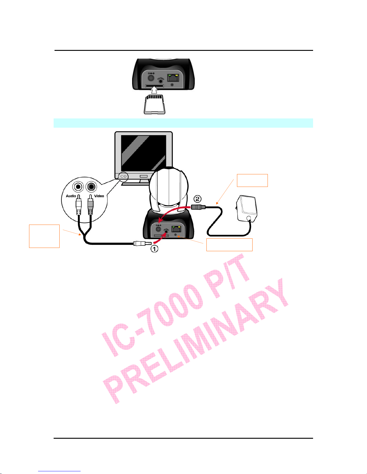
How to insert SD card:
Microphone
LED
(For status display)
IR LEDX6
Reset Switch
DC JACK
RJ-45 JACK
TV_OUT JACK
SD Card Slot
Focus ring
(For focus adjustment)
Page 8
`
IC-7000 CAM User’s Guide
PPaann//TTiilltt IIPP SSuurrvveeiillllaannccee CCaammeerra
a
IC-7000 USER’S GUIDE PAGE 8/62 Rev. PV1.0
1.7 HOW TO CONNECT THE CAMERA TO TV SET
z 1. Insert the TV_OUT cable to the TV-Out jack located at the back of camera, as shown in
Figure (1).
z 2. Connect the power adapter to camera, as shown in Figure (2). Press and hold Reset
switch for three seconds. Then, release it. The camera will switch to TV_OUT mode.
z 3.How to use TV_OUT function:
a. Hold to change TV output mode: Default TV-OUT mode is NTSC, if you want to use
PAL system, press and hold Reset switch about three seconds to
switch TV output mode between NTSC and PAL system.
b. Push to exit : Press Reset button to access into TV screen and adjustable
50Hz,60Hz,Outdoor
Reset Switch
TV_OUT
Cable
Adapter
Page 9

`
IC-7000 CAM User’s Guide
PPaann//TTiilltt IIPP SSuurrvveeiillllaannccee CCaammeerra
a
IC-7000 USER’S GUIDE PAGE 9/62 Rev. PV1.0
1.8 PRODUCT SET-UP
2. UTILITIES AND TOOLS
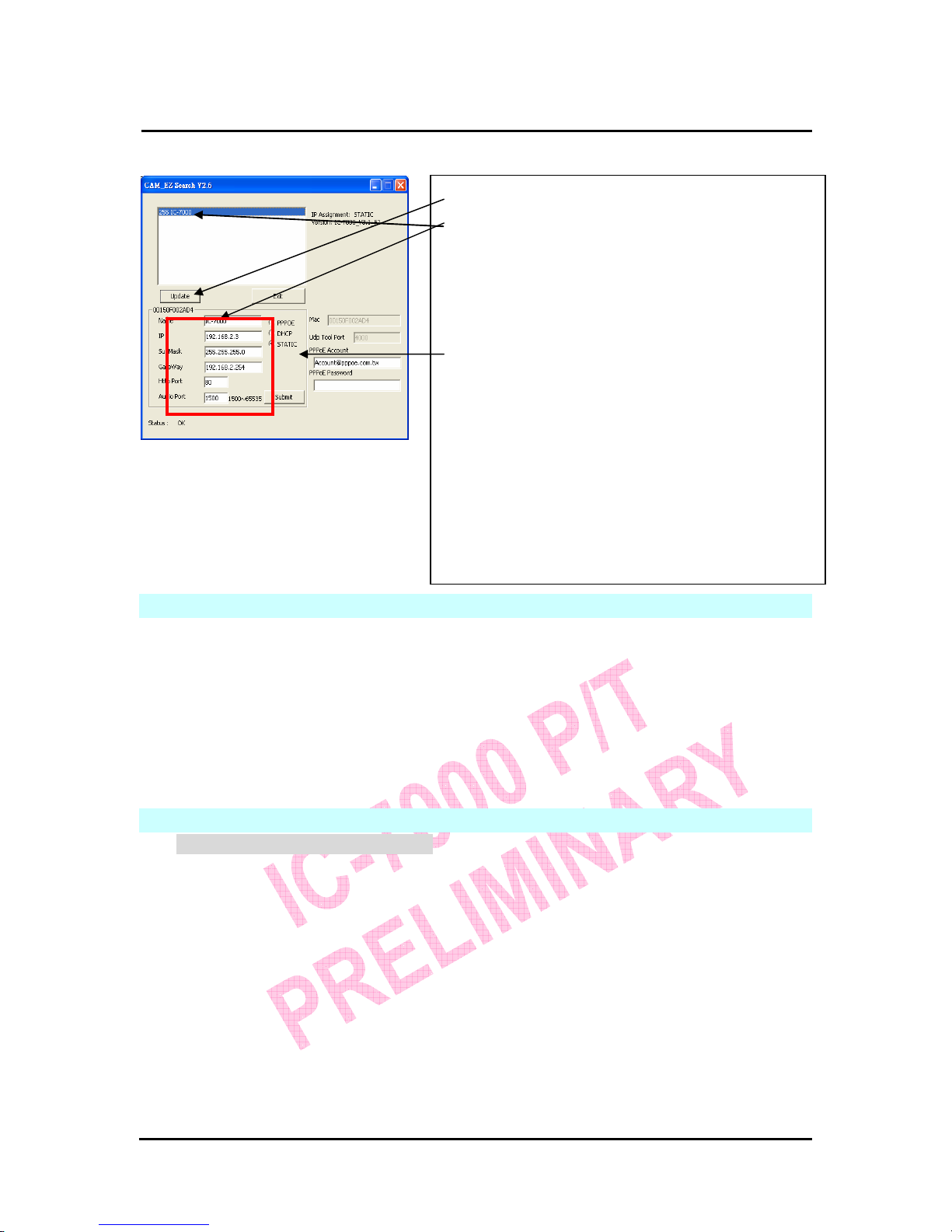
2.1 CAM_EZ SEARCH
CAM_EZ Search is a camera search utility comes with this product. It can search all IP
CAMs connected to LAN by sending broadcasting packets. After IP CAM responds the
inquery packet, the utility will display a list of all IP CAM found on LAN. And it allows you
to modify the settings of specified IP CAM, such as IP address or the name of IP CAM.
CAM_EZ Search Screen
Anchor
Frame
Screw (P head
M3.5X25)
Page 10

`
IC-7000 CAM User’s Guide
PPaann//TTiilltt IIPP SSuurrvveeiillllaannccee CCaammeerra
a
IC-7000 USER’S GUIDE PAGE 10/62 Rev. PV1.0
figure 1
圖(一)
2.2 USE IP-CAM AND TEST THE FUNCTIONALITY FOR THE FIRST TIME
The following ※ network architecture is suitable for IP-CAM test/ IP address change
(static IP address) /firmware update (strongly recommended).
Please refer to the following instructions:
A. Installing the camera for the first time:
z You computer must be equipped with network card and RJ-45 network
connector.
z Connect the RJ-45 jack which is located at the rear of IP-CAM with the red
test network cable. One end is connected to the network jack of computer;
the other end is connected to the network jack located at the rear side of the
IP-CAM.
z Connect the power adaptor to the power port (on the rear) of IP-CAM. Now,
the status LED on the top of IP-CAM will be illuminated.
Audio Port
number
(UDP)
Submit
settings
PPPoE Account
Choose the
way to get IP
IP address
Communication Port
Default Gateway
Subnet Mask
MAC address
Renew List
IP CAM List
IP CAM Name
Version of
CAM_EZ
Search
Version of IP CAM
Display the way
to
g
et IP
Renew
executed to
obtain an IP
Key in PPPoE
Page 11

`
IC-7000 CAM User’s Guide
PPaann//TTiilltt IIPP SSuurrvveeiillllaannccee CCaammeerra
a
IC-7000 USER’S GUIDE PAGE 11/62 Rev. PV1.0
B. Make sure the IP addresses of PC and IP CAM are on the same network
section:
z Usually, static IP address will be used to access Internet, so the IP
address will vary. When you want to change IP address, please write
down the original IP address on your computer first. Then you have to
modify the IP address of your computer for testing if the IP-CAM can be
operated normally or not. After finishing the test, IP address for your
computer should be recovered to original settings.
z In general, the IP address for your computer in LAN will be set with
“Obtain an IP address automatically”. To test the IP-CAM is working
properly or not, the IP address of your computer must be changed
temporarily. After the test is finished, it can be changed back to original
setting.
C. Next, choose Control Panel->Network Connections->choose the activated
area
Network Connections---> right click your mouse --->select Properties(P)--->
Select Internet Protocol (TCP/IP)---> Select Properties(R) , then you can
check the current IP address status for the computer. The way to modify IP
address is:
D. Open and execute CAM_EZ Search (as shown in Figure 2). The system will
scan the IP-CAM that you just installed automatically. Then, you will find
255IC-7000 in the column of Camera Lists. Click 255IC-7000 with left mouse
button. You can see the default settings of IP-CAM.
IP Address(I):1 92.168.9.5
Subnet Mask (U):255.255.255.0
Default Gateway(D):192.168.9.254
Page 12
`
IC-7000 CAM User’s Guide
PPaann//TTiilltt IIPP SSuurrvveeiillllaannccee CCaammeerra
a
IC-7000 USER’S GUIDE PAGE 12/62 Rev. PV1.0
Figure 2
2.3 NETWORK SETUP
Before you set up IP CAM, you have to know how your ISP provide you with IP address
(static or dynamic). If you do not know, please contact your ISP and ask for help.
Common network architecture (1 ~ 7 types).is listed in section 2.5, you can refer to the
listing to find out which type is suitable for your computer and finish the setting as the
instructions given in section 2.5. To set up IP-CAM and IP address, the common way that
people use is to change the obtaining of IP address of IP-CAM**. Detailed information is
listed in section 2.4-1 to 2.4.3.
2.4 SETTING THE WAY HOW IP-CAM OBTAIN IP ADDRESS
2.4-1 STATIC - IP Address Setting
z You computer must be equipped with network card and RJ-45 network jack.
z Connect the RJ-45 jack on the rear of IP-CAM with the red test network
cable. One end is connected to the network card of computer; the other end
is connected to the network jack located at the rear of the IP-CAM.
z Connect the power adaptor to the power jack (on the rear of IP-CAM). Now,
the status LED on the top of IP-CAM will be illuminated.
Step 1. Click Update. You can see 255IC-7000.
Step 2. Click 255IC-7000. You can see
Name : IC-7000
IP : 192.168.9.1
SubMask :255.255.255.0
GateWay :192.168.9.254
HTTP Port :Http communication port. The default
setting is 80.
AudioPort: Port used for audio transmission,
default setting is 1500.
Step 3. Make sure the IP setting is STATIC.
Step 4. Double click on 255IC-7000 to launch the
browser. Type ID/Password to login and get accessed to
network monitoring screen (for detailed information,
please refer to 3.1). If you can see the image displayed in
web browser, it means that IP-CAM is working properly.
Page 13

`
IC-7000 CAM User’s Guide
PPaann//TTiilltt IIPP SSuurrvveeiillllaannccee CCaammeerra
a
IC-7000 USER’S GUIDE PAGE 13/62 Rev. PV1.0
z Open and execute CAM_EZ Search (as shown in Figure 3). The system will
scan the IP-CAM that you just installed automatically. Then, you will find
255IC-7000 in the column of Camera Lists. Click 255IC-7000 with left
mouse button. You can see the default settings for IP-CAM.
Figure 3
z Fill static IP Address as shown below. (If you do not know your IP address,
please contact your ISP. An example of static IP Address modification.is
shown below)
Step 4. Type Fixed IP.
Name :
IC-7000
IP : 211.78.174.94
SubMask :255.255.255.248
GateWay :211.78.174.89
HTTP Port:Http communication port. The
default setting is 80.
(If you have multiple IP-CAMs installed in the
same network, you have to divide them
with different Port numbers, e.g, 1025、
1026、1039…..)
UDP Port : UDP Port,Pre-setting is 1500
Step 5. Choose STATIC.
Step 6. After finishing the settings, click Submit. The
network settings for IC-7000 IP-CAM will be renewed.
Step 1. Click Update. You can see 255 IC-7000.
Step 2. Click 255
IC-7000. You can see
Name :
IC-7000
IP : 192.168.2.3
SubMask :255.255.255.0
GateWay :192.168.2.254
HTTP Port:Http communication port. The
default setting is 80.
(If you have multiple IP-CAMs installed in
the same network, you have to divide them with
different Port numbers, e.g, 1025、1026、1039….)
UDP Port : UDP port,Pre-setting is 1500
Step 3. Make sure the IP setting is STATIC.
Page 14
`
IC-7000 CAM User’s Guide
PPaann//TTiilltt IIPP SSuurrvveeiillllaannccee CCaammeerra
a
IC-7000 USER’S GUIDE PAGE 14/62 Rev. PV1.0
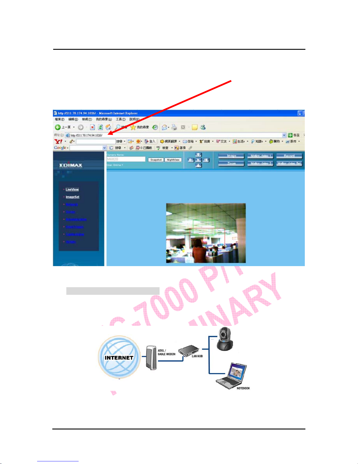
Example:
1. Set up the IP CAM with static IP address.
2. Turn on your computer and launch IE browser. Type 211.78.174.94:(
1025、
1026、1039….)
in the Address line. Now you can see the monitoring screen on
web browser.
2.4-2 DHCP - IP Address Setting:
z Use RJ-45 Ethernet cable (red) to connect ADSL host and LAN hub. Then
use RJ-45 Ethernet cable (blue) to connect PC and IP CAM (as shown
below).
z Connect the power adaptor to the power port (on the rear) of IP-CAM. Now,
the status LED on the top of IP-CAM will be illuminated.
z Set up the connection way inside the PC network: Please go to
Page 15

`
IC-7000 CAM User’s Guide
PPaann//TTiilltt IIPP SSuurrvveeiillllaannccee CCaammeerra
a
IC-7000 USER’S GUIDE PAGE 15/62 Rev. PV1.0
Control Panel ---> Network Connections ---> Choose Activated LAN
connection ---> right click your mouse ---> Select Properties(P)---> Select
Internet Protocol (TCP/IP)---> Select Properties(R)
--->Click Obtain an IP address automatically(O), Obtain DNS server address
automatically(B).
z Start CAM_EZ Search utility (as shown in Figure 3). Press Update to scan
the IP-CAM that you just installed automatically. Then, you will find
255IC-7000 in the column of Camera Lists. Click 255IC-7000 with left
mouse button. You can see the default settings for IP-CAM.
Obtain an IP address automatically (O)
Obtain DNS server address
automatically (B)
Step 1. Click Update. You can see 255 IC-7000.
Step 2. Click 255
IC-7000. You can see
Name :
IC-7000
IP : 192.168.2.3
SubMask :255.255.255.0
GateWay :192.168.2.254
HTTP Port:Http communication port. The
default setting is 80.
Step 3. Choose DHCP.
Step 4. After finishing the settings, click Submit. The
network settings for IP CAM IP-CAM will be
renewed. (That is, you can obtain a virtual IP
address)
Page 16

`
IC-7000 CAM User’s Guide
PPaann//TTiilltt IIPP SSuurrvveeiillllaannccee CCaammeerra
a
IC-7000 USER’S GUIDE PAGE 16/62 Rev. PV1.0
Figure 5
Example:
1. Now, IP-CAM is set up with an IP address in LAN.
2. Or, use CAM_EZ Search to access the monitoring screen according to the
instructions given in Figure 5.
3. Or, turn on your PC and launch IE Browse. Type 10.1.10.82 in Address bar
to access the monitoring screen.
Step 5. Click Update. You can see 255IC-7000.
Step 6. Click 255IC-7000. You can see the change of
IP-CAM:
Name : IC-7000
IP : 10.1.10.82
SubMask :255.255.0.0
GateWay :10.1.10.252
HTTP Port:Http communication port. The
default setting is 80.
Step 7. The IP setting is DHCP.
Step 8. Double click 255IP CAM to open IE browser to
access into network monitoring screen.
Page 17

`
IC-7000 CAM User’s Guide
PPaann//TTiilltt IIPP SSuurrvveeiillllaannccee CCaammeerra
a
IC-7000 USER’S GUIDE PAGE 17/62 Rev. PV1.0
2.4-3 PPPoE - IP Address Setting
z Access into monitoring screen of network by following the instruction given
in section 2.2.
z Click ‘Network’ on the left, please fill PPPoE account and password in
corresponding field, click ‘submit’ to save settings, and click ‘reboot’ to
restart web browser.
z Start CAM_EZ Search utility and click Update. Wait for 60 seconds (it varies
according to the connection quality). Then the system will search IC-7000
IP-CAM automatically. 1. Click the IP-CAM in the list. 2. Check the IP
address and Gateway. IP address obtained from ISP, SubMask and
Gateway will be shown in dimmed color. It means that IC-7000 IP-CAM
found is working properly with PPPoE.
1.
2.
Page 18

`
IC-7000 CAM User’s Guide
PPaann//TTiilltt IIPP SSuurrvveeiillllaannccee CCaammeerra
a
IC-7000 USER’S GUIDE PAGE 18/62 Rev. PV1.0
z You can also use CAM_EZ Search utility to setup PPPoE account and
password.
z Select PPPoE. Click Submit to send out. The IC-7000 IP-CAM network
settings will be renewed.
z Now you can click the searched IP-CAM to open IE Browser to log onto
IP-CAM web configuration utility automatically.
I
NSTALL IP-CAM IN AN EXISTED NETWORK ENVIRONMENT
Scenario 1
The way to access Internet ADSL or Cable Modem
Public IP address required? Yes, several public IP addresses are required
for multiple IP-CAMs
DHCP server required? No
Network Setup for IP -CAM LAN Enable / Manually
This scenario is best for: Users with several static public IP addresses
and multiple IP-CAMs.
1. Connect the red test network cable to the RJ-45 Ethernet jack located on the rear
of IP-CAM. The other end is connected to the network card of computer.
Page 19

`
IC-7000 CAM User’s Guide
PPaann//TTiilltt IIPP SSuurrvveeiillllaannccee CCaammeerra
a
IC-7000 USER’S GUIDE PAGE 19/62 Rev. PV1.0
2. Refer to 2.4-1 STATIC – IP Address Settings to input the IP address properly.
3. Set a static public IP address for each IP-CAM.
4. To view the image of IP-CAM from remote computer: Open IP browser and type in
the IP address of the IP-CAM, e.g., http://211.78.174.03.
Scenario 2
The way to access Internet ADSL or Cable Modem
Public IP address required? Yes, only one public IP address is required
DHCP server required? Yes
Network Setup for IP -CAM LAN Enable / Manually
Every IP-CAM need an unique port number
This scenario is best for: Users with one public fixed IP addresses,
residential router and several IP-CAMs
installed in local network.
1. Set a public IP address (e.g., 211.78.174.01) for the public IP of residential router.
Then, set the private IP address and activate the DHCP server function of residential
router.
2. In the IP configuration for each IP-CAM, please assign different private IP address.
In the Http Port setting, please give every IP CAM an unique port number. (Please
Page 20

`
IC-7000 CAM User’s Guide
PPaann//TTiilltt IIPP SSuurrvveeiillllaannccee CCaammeerra
a
IC-7000 USER’S GUIDE PAGE 20/62 Rev. PV1.0
refer to 2.4-1 STATIC - IP Address Settings to get instructed.)
3. For the instruction of port mapping function of residential router, please refer to IP
and port settings of camera to make proper configuration.
4. To view the image of IP-CAM from remote computer: Launch IP browser and type
the public IP address of the residential router and the port number of IP-CAM, e.g.,
http:// 211.78.174.01:1025.
Scenario 3
The way to access Internet ADSL or Cable Modem
Public IP address required? Yes, a dynamically-located IP address is
required
DHCP server required? Must be equipped with DHCP and NAT
function
Network Setup for IP -CAM LAN Enable / Manually
Every IP-CAM need an unique port number
This scenario is best for: Users with dial-up ADSL, one dynamic IP
address and several IP-CAMs installed
1. Activate PPPoE function of residential router. Then, set private IP address and
activate the DHCP server function of residential router. When the dial-up procedure of
ADSL is completed, you will get a dynamically-allocated IP address from your ISP.
2. In the IP configuration for each IP-CAM, please assign an unique private IP address
for every IP CAM. For Http Port setting, please specify an unique port number for
each IP CAM also. (Please refer to 2.4-1 STATIC - IP Address Settings to get
instructed)
3. For the instruction of port mapping function of residential router, please refer to IP
Page 21

`
IC-7000 CAM User’s Guide
PPaann//TTiilltt IIPP SSuurrvveeiillllaannccee CCaammeerra
a
IC-7000 USER’S GUIDE PAGE 21/62 Rev. PV1.0
and port settings of camera to make proper configuration.
4. To view the image of IP-CAM from remote computer: Launch IP browser and type
the public IP address of the residential router and the port number of IP-CAM, e.g.,
http:// 211.78.174.01:1025
Scenario 4
The way to access Internet ADSL or Cable Modem
Public IP address required? Yes, one public address is required
DHCP server required? No
Network Setup for IP -CAM LAN Enable / Manually
This scenario is best for: Users with one public physical IP address and
one IP-CAM.
1. Connect the red test network cable to the RJ-45 Ethernet jack located on the rear of
IP-CAM. The other end is connected to the network card of computer.
2. Refer to 2.4-1 STATIC – IP Address Settings to input IP address properly.
3. Set up the IP-CAM with a public IP address.
4. To view the image of IP-CAM from remote computer: Launch IP browser and type
the public IP address of the residential router and the port number of IP-CAM, e.g.,
http:// 211.78.174.01:1025
Page 22

`
IC-7000 CAM User’s Guide
PPaann//TTiilltt IIPP SSuurrvveeiillllaannccee CCaammeerra
a
IC-7000 USER’S GUIDE PAGE 22/62 Rev. PV1.0
Scenario 5
The way to access Internet ADSL or Cable Modem
Public IP address required? Yes, one dynamically-allocated public IP
address is required
DHCP server required? No
Network Setup for IP -CAM PPPoE function should be set, LAN Enable
This scenario is best for: Users with dial-up ADSL, and one IP-CAM
installed
1. Please obtain the PPPoE username and password from your ISP.
2. Connect the red test network cable to the RJ-45 Ethernet jack located on the rear of
IP-CAM. The other end is connected to the network card of computer.
3. Refer to 2.4-3 PPPoE - IP Address Settings to input account name and password.
4. Please setup the Mail server setup information in IP-CAM setup utility.
5. Activate the
Dial up function of IP-CAM to get connected to internet by ADSL
Modem.
6. When the dial-up is successful, IP-CAM will send a notification e-mail of dynamic IP
Address to the users.
7. Launch IE browser and type in the public IP address (such public IP is
dynamically-allocated by your ISP) of the IP-CAM, e.g., http://211.78.174.94.
Page 23

`
IC-7000 CAM User’s Guide
PPaann//TTiilltt IIPP SSuurrvveeiillllaannccee CCaammeerra
a
IC-7000 USER’S GUIDE PAGE 23/62 Rev. PV1.0
Scenario 6
The way to access Internet ADSL or Cable Modem
Public IP address required? Yes, one dynamically-allocated public IP
address is required
DHCP server required? Must be equipped with DHCP and NAT
function
Network Setup for IP -CAM LAN Enable / Manually
This scenario is best for: Users with several dynamic IP addresses and
several IP-CAMs installed
1. Please obtain the PPPoE username and password from your ISP.
2.
Connect the red test network cable to the RJ-45 Ethernet jack located on the rear of
IP-CAM. The other end is connected to the network card of computer
3.
Refer to 2.4-3 PPPoE - IP Address Settings to input PPPoE account and password.
4. Please type the Mail server setup information in IP-CAM setup utility.
5.
Connect IP-CAM to LAN Hub.
6. Use CAM_EZ Search utility to find out the dynamic IP address assigned by ISP for
each IP-CAM.
7. Open IP browser and type in the physical IP address (such float IP is dispatched by
ISP) of the IP-CAM, e.g., http://211.78.174.94.
8. Follow the steps above to configure for each IP-CAM.
二. IP-CAM Network Framework Installation 7
The way to access Internet ADSL or Cable Modem
Public IP address required? One static public IP address required
DHCP server required? Must be equipped with DHCP and NAT
Page 24

`
IC-7000 CAM User’s Guide
PPaann//TTiilltt IIPP SSuurrvveeiillllaannccee CCaammeerra
a
IC-7000 USER’S GUIDE PAGE 24/62 Rev. PV1.0
functions
Network Setup for IP -CAM LAN Enable / Manually
This scenario is best for: Users with one static public IP address,
several IP-CAMs installed, used residential
router to access internet
1. Set a public IP address (e.g., 211.78.174.01) for the public IP of your residential
router, which is assigned by your ISP. Then, set another private IP address and
activate DHCP server function of residential router.
2. For the IP configuration for each IP-CAM, please assign an unique private IP
address for every IP-CAM. In the Http Port setting, please give an unique port
number to every IP-CAM (Please refer to 2.4-1 ST ATIC - IP Address Settings to set
IP address properly.)
3. For the instruction of port mapping function of residential router, please refer to IP
and port settings of camera to make proper configuration.
4. To view the image of IP-CAM from remote computer: Launch IP browser and type
the public IP address of the residential router and the port number of IP-CAM, e.g.,
http:// 211.78.174.01:1025.
Page 25

`
IC-7000 CAM User’s Guide
PPaann//TTiilltt IIPP SSuurrvveeiillllaannccee CCaammeerra
a
IC-7000 USER’S GUIDE PAGE 25/62 Rev. PV1.0
2.5 INSTALLATION PROCEDURE FOR NETWORK ENVIRONMENT WITH RESIDENTIAL ROUTER
When a residential router is installed in network, IP-CAM can obtain a dynamic IP address
from the DHCP server of residential router. If you want to access IP-CAM from internet, a static
private IP address must be assigned to IP-CAM.
(1) Please use CAM_EZ Search to set a static IP address for IP-CAM, e.g.,
192.168.0.120 and change the http port number (1025~35534). ( refer to Figure
1)
Figure 1
(2) Type admin to access into ADSL router’s web configuration. (Refer to Figure 2)
NOTE: The following setup procedure may very when you’re using different residential router,
please refer to the user manual of your residential router to get instructed.
Figure 2
Page 26

`
IC-7000 CAM User’s Guide
PPaann//TTiilltt IIPP SSuurrvveeiillllaannccee CCaammeerra
a
IC-7000 USER’S GUIDE PAGE 26/62 Rev. PV1.0
(3) Enable DHCP function of residential router. (Refer to Figure 3. The range of available IP
address is 192.168.0.100~192.168.0.199)
Figure 3
(4) Access into the web page of Virtual Server. Add the fixed IP address specified by CAM_EZ
Search in step (1) and enable it. (Refer to Figure 4.1)
Figure 4.1
Page 27

`
IC-7000 CAM User’s Guide
PPaann//TTiilltt IIPP SSuurrvveeiillllaannccee CCaammeerra
a
IC-7000 USER’S GUIDE PAGE 27/62 Rev. PV1.0
(5) Restart PC and residential router. After restarted, if you want to connect IP-CAM from
internet, please go to Status\WAN\IP Address of the router’s web configuration interface.
(http://59.104.28.251:5000, refer to Figure 5)
Figure 5
2.6 WORK-AROUND FOR AUDIO PROBLEM WITH RESIDENTIAL ROUTER
If you found that the audio function of IP-CAM is not working properly, please follow the
following instructions to fix this problem:
1. Assign a new audio port number, default value is 1500 (available value from 1500 to
25535), press ‘Submit’ after a new value has been entered.
Page 28

`
IC-7000 CAM User’s Guide
PPaann//TTiilltt IIPP SSuurrvveeiillllaannccee CCaammeerra
a
IC-7000 USER’S GUIDE PAGE 28/62 Rev. PV1.0
2. Add a new UDP port on your residential router (available value from 1500 to 25535),
every IP-CAM must have an unique port number.
Page 29

`
IC-7000 CAM User’s Guide
PPaann//TTiilltt IIPP SSuurrvveeiillllaannccee CCaammeerra
a
IC-7000 USER’S GUIDE PAGE 29/62 Rev. PV1.0
3. GETTING STARTED
3.1 SYSTEM LOGIN
The system login is the procedure to identify users grant proper permission to a user.
There are 2 kinds of user in this IP-CAM: “administer” and “general user”. After a user is
authenticated and logged onto the system, he or she can get video / audio from IP-CAM,
or modify setting of IP-CAM.,Please follow the following steps below to log in as
an ”admin” user:
Step 1: Launch the login window, as shown below.
Using the CAM_EZ Search utility, select the IC-7000 from the menu , and double click on
it ; .
Step 2: The system login window will appear in your browser as shown below:
Step 3: Enter Account ID and Password (the default settings are “admin” and “1234”)
Step.4 Press Submit after ID and password has been entered, and then follow the
instructions for the
feature show on next page ;
Step.5 If your typed wrong ID and/or password, please press Cancel try again.
1.
Page 30

`
IC-7000 CAM User’s Guide
PPaann//TTiilltt IIPP SSuurrvveeiillllaannccee CCaammeerra
a
IC-7000 USER’S GUIDE PAGE 30/62 Rev. PV1.0
3.2 LIVEVIEW
When you’re using IP Cam for the first time, you must change the Internet Explorer
security settings (please refer to section 3.2.1
to get instructed). Otherwise, the system
will display the following warning, and be unable to display the image of IP-CAM.
After the security setting of Internet Explorer has been changed, you don’t have to modify
it again in the future.
3.2.1 The IE security settings can be changed by following the instructions listed below:
Step 1. IE Toolbar ---> Tools ---> Internet Options ---> Security ---> Custom Level …
Page 31

`
IC-7000 CAM User’s Guide
PPaann//TTiilltt IIPP SSuurrvveeiillllaannccee CCaammeerra
a
IC-7000 USER’S GUIDE PAGE 31/62 Rev. PV1.0
Step 2. After clicking Custom Level …, a security settings window will appear.
Change ActiveX Control Options and Plug-ins settings to the following new setting:
1. Download signed ActiveX controls: Enable
2. Download unsigned ActiveX controls: Enable
3. Initialize and script ActiveX controls not marked as safe: Enable
4. Run ActiveX controls and plug-ins: Enable
5. Script ActiveX controls marked safe for scripting: Enable
Step 3. After clicking “ok”, a warning window will appear. Click on “Yes” , and you will
return to the last window. Press “OK”, and the setup is complete.
Page 32

`
IC-7000 CAM User’s Guide
PPaann//TTiilltt IIPP SSuurrvveeiillllaannccee CCaammeerra
a
IC-7000 USER’S GUIDE PAGE 32/62 Rev. PV1.0
Step 4. At this time, the computer will display a warning window, as shown below :
Press “Yes” , to proceed;
Step 5. When the installation is complete , you may begin to view the surveillance
image of IP-CAM, as shown below.
Note: This action loads ActiveX components from the IC-7000 System to the local machine. To
ensure your machine will not execute malicious ActiveX codes from the Internet without your
permission, you will be prompted to allow the ActiveX component of your browser to interact
with the IC-7000 each time you access it. When you view the video stream from the IC-7000
IP-CAM and you see the prompts regarding downloading, running or enabling ActiveX content
from the IP address of the IC-7000 IP-CAM, click “Yes” to allow your computer to display the
video from IP-CAM .If you are prompted to allow ActiveX content when you are not connected
to your IP-CAM , please ensure the provider of the content is a reliable and secure source for
Page 33

`
IC-7000 CAM User’s Guide
PPaann//TTiilltt IIPP SSuurrvveeiillllaannccee CCaammeerra
a
IC-7000 USER’S GUIDE PAGE 33/62 Rev. PV1.0
running programs on your PC. If you are in doubt about the source of the ActiveX program you
are being requested to allow to run on your system , click “No” to ensure that no malicious
codes will be executed on your PC .
3.3 TAKE A SHOT
This function allows users to capture the screenshot as a picture, and save it on your
computer.
Please follow the following instructions:
Step 1. Go to the
menu, and go to the live image.
Step 2: Hold down the Ctrl key on your keyboard;
Step 3. Place the mouse cursor on the surveillance image and left click with your mouse.
The captured image should flash momentarily, as shown below:
(you can also press
button to do this)
Step 4. Release the Ctrl key, and the single still shot image will be stored on your
computer.
Step 5. Select the
menu to browse through the captured images. Refer to
Chapter 錯誤! 找不到參照來源。 for detailed information.
Note: Snapshot can only be stored to PC, can't store to SD Card which is inserted in the IP-CAM.
Page 34

`
IC-7000 CAM User’s Guide
PPaann//TTiilltt IIPP SSuurrvveeiillllaannccee CCaammeerra
a
IC-7000 USER’S GUIDE PAGE 34/62 Rev. PV1.0
4. ADVANCED FUNCTION OF LIVEVIEW
Move the cursor to the live image, and right click with your mouse. A small menu will appear with
four options:
- Image:Adjust image parameters
- Record:Setup for recording video in AVI format.
- Zoom:Adjust digital zoom parameters.
- Motion Detec Set:Adjust settings for motion detection.
These settings will be described in detail in the next section.
4.1 IMAGE ADJUSTMENT
After selecting an image, you may change various image settings, as shown below:
( )
Page 35

`
IC-7000 CAM User’s Guide
PPaann//TTiilltt IIPP SSuurrvveeiillllaannccee CCaammeerra
a
IC-7000 USER’S GUIDE PAGE 35/62 Rev. PV1.0
4.2 AVI RECORD SETUP
By selecting “Record”, you can adjust the AVI Frame Rate (i.e. how many frames per
second) settings and the name of video file.
(
):
4.3 IMAGE ENLARGEMENT
If you want to enlarge a portion of image, press and hold left mouse key and move the
mouse to select a square area in the image, as shown by the grey box in the image below.
The area you select will be enlarged like the example shown below: (
)
Page 36

`
IC-7000 CAM User’s Guide
PPaann//TTiilltt IIPP SSuurrvveeiillllaannccee CCaammeerra
a
IC-7000 USER’S GUIDE PAGE 36/62 Rev. PV1.0
4.4 MOTION DETECTION SETUP
Setting up the Motion Detection (MD) values, including the first area (red border) and
second area (green border).
Please check whether the event trigger has been enabled or not first, then you can setup
parameters of motion detection as described below:
- Reset MD range: Select motion detect 1 or 2, and hold down on the left mouse button
(this will appear as the upper left corner of the MD range). Then, drag out the desired
range, and release when finished.
( , )
- Cancel MD: Same as above, but just left click once and release. This will cancel the
MD (Motion Detection).
- Motion_detec_set: This sets the MD (Motion Detection) sensitivity, which is usually set
to a value of 5. This means that the motion detection will be triggered with as little of a
5% change within the MD range. The lower the number your entered, the higher the
sensitivity of the MD.
( ) will be.
When motion is detected, the screen should display an MD warning in red in the upper
left hand corner if there is movement within MD1 or MD2, as shown in below:
- Any motion detection range can be selected in 640x480 and 320x240 resolutions
Page 37

`
IC-7000 CAM User’s Guide
PPaann//TTiilltt IIPP SSuurrvveeiillllaannccee CCaammeerra
a
IC-7000 USER’S GUIDE PAGE 37/62 Rev. PV1.0
- In 160x120 resolution, the motion detection is fixed to the entire image.
Note:
1. Motion detection can exist PC and SD Card **
2. Image will be stored to ‘C: \tmp\webmd’ directory.
4.5 MOTOR CONTROL
1. — Home , return to the middle place.
2. — Up, press it to move camera up.
3. — Down , press it to move camera down.
4.
— Left, press it to move camera left.
5.
— Right , press it to move camera right.
6. — Auto , after press this bottom, camera will pan between left and right automatically.
5. ADVANCED APPLICATION
This section describes the advanced settings of the IC-7000 IP-CAM, including:
- Image Setup
- Capture View
- Network Setup
- Server Setup
- Event Trigger Setup
- Administration Setup
- Software Update
5.1 IMAGE SETUP
This includes:
- Resolution:Users can select between image resolution of 160x120, 320x240, and
640x480. The default resolution is 320x240.
- Quality: Users can select between “fine”, “normal”, and “basic” image quality. The
default image quality is “basic”.
- Anti-Flicker:Users can select between 60Hz for USA and Canada, 50Hz for Australia
and Europe, or Outdoor for when you are using this camera in an environment without
artificial light; The default setting is 50Hz.
- Audio:Audio output. Default setting is “off”.
- Rotate 180: This setting turns the image upside-down for when the camera is mounted
to a ceiling; Default setting is “off”.
- IR Auto Detection:IR LED will be activated automatically when there’s no enough light.
Default setting is “on”
- Message: LiveView characters are hidden,
Default setting is “on”**
Instructions for image setup:
Step 1. Click
to enter imageset menu, the default settings are shown
Page 38

`
IC-7000 CAM User’s Guide
PPaann//TTiilltt IIPP SSuurrvveeiillllaannccee CCaammeerra
a
IC-7000 USER’S GUIDE PAGE 38/62 Rev. PV1.0
below:
Step 2. After entering the desired values, click Submit.
Step 3. if you want to discard changes, click Cancel
5.2 CAPTURE VIEW
This view includes:
- Capture still images using LiveView.
-
Capture still images via MD automatically.
How to Use Capture View:
Step 1. Click
to enter captureview menu. The menu is capable of saving
up to 48 images, viewable on three pages. Images saved by motion detection function
will not be shown here;
Step 2. You can set the system to read image from either your computer or your SD
Page 39

`
IC-7000 CAM User’s Guide
PPaann//TTiilltt IIPP SSuurrvveeiillllaannccee CCaammeerra
a
IC-7000 USER’S GUIDE PAGE 39/62 Rev. PV1.0
Memory card. After your selection has been chosen, click on Apply.
Step 3. Select desired thumbnail image using the mouse cursor to view image at the
default dimensions.
Note: When you’re using function to view images, when you select ‘PC’ at
‘View From’, you’re viewing the image of snapshot; when you select ‘FlashCard’, you’re
viewing the image captured by motion detection function. If you want to save images captured
by motion detection function to your PC, images will be stored in C:\tmp\webmd directory.
5.3 EVENT TRIGGER
This function includes both event trigger settings and display:
- Event: Entering events
- Trigger:Setting trigger and picture capture times
Detailed descriptions can be found in the next chapter.
Page 40

`
IC-7000 CAM User’s Guide
PPaann//TTiilltt IIPP SSuurrvveeiillllaannccee CCaammeerra
a
IC-7000 USER’S GUIDE PAGE 40/62 Rev. PV1.0
5.3.1 Event
Event settings, including:
- Motion Detection (set 1)
- Motion Detection (set 2)
Individual or both set signal input triggers can be selected.
How to Use Event Settings:
Step 1. Activate Event for either set (Trigger sensitivity will be displayed automatically
for MD)
Step 2. After you finished, click Submit; otherwise;
Step 3. Click Default to use factory default settings (sets all to off).
Note: After engaging either type of event, “Save in PC” will be switched on
automatically.
5.3.2 Trigger
Event trigger image transfer settings, including:
- Save in PC:The image file is saved in your computer.
- Save in Flash Card:The image file is saved in the SD card.
- Mail Image:Send captured event trigger image file by e-mail.
- FTP Image: Send captured event trigger image file by FTP.
- Shutter Timer:Change shutter time for event trigger image capture; Default setting is 2
seconds.
5.4 NETWORK SETUP
Network Setup can be used to change the network settings of the IP CAM. The default
setting for IP assignment is “static”. Available settings are:
- IP Assignment:Static, DHCP, or PPPoE
- PPPoE settings (PPPoE is the most common type of Broadband Internet connection,
where your ISP assigns a different IP address to your connection each time you log on)
- Http Server port settings
- Audio Port Settings
- DNS settings
MAC Address:Displays the Mac address of the IP CAM
Page 41

`
IC-7000 CAM User’s Guide
PPaann//TTiilltt IIPP SSuurrvveeiillllaannccee CCaammeerra
a
IC-7000 USER’S GUIDE PAGE 41/62 Rev. PV1.0
IP Assignment:
Static IP Assignment refers to the IP address assigned by your ISP (or IT department of
your company)
IP Address: Includes Static, DHCP and PPPoE. IP addresses assigned through DHCP
and PPPoE are generally dynamic.
When using the “Static” setting, you must enter the following information:
- IP Address:The IP address of the IP CAM
- Subnet Mask:Set by default to 255.255.255.0
- Gateway:Default gateway
When using the “DHCP” setting, you do not need to enter any of the above settings.
When using the “PPPoE” setting, you must enter your PPPoE account and password.
5.4.2 PPPoE
This menu allows you to enter the dial-up settings when you’re using PPPoE. You have
to enter PPPoE ID and password here.
How to Setup PPPoE
Step 1. Enter your PPPoE user ID in the “Account” field.
Step 2. Enter your PPPoE password in the “Password” field.
Step 3. Click Submit to complete setup procedure.
Page 42

`
IC-7000 CAM User’s Guide
PPaann//TTiilltt IIPP SSuurrvveeiillllaannccee CCaammeerra
a
IC-7000 USER’S GUIDE PAGE 42/62 Rev. PV1.0
Note: Some ISP assigns IP address dynamically, so the IP address you obtained from
ISP for the IC-7000 IP-CAM may very every time when you connected to
internet, and there will be problem when you want to connect your IP-CAM
from the other computer on internet. To solve this problem, you can use a
residential router which comes with DDNS client with this IP-CAM.
5.4.3 HTTP Server
This menu allows you to enter the port number of the IC-7000 IPCAM internal
web server (or HTTP Server) via HTTP protocol. The default port number is
“80”.
5.4.4 DNS Server
This menu allows you to enter the IP address of the DNS (Domain Name Service) server.
By doing this, you can replace the IP address of the IP CAM with an http name (such as
myIPCAM.XXX), making it easier to remember. The default DNS1 value is “168.95.1.1”
(Hinet/CHT). If the connection fails, the system will automatically attempt to connect to
the IP address of DNS2. ** DNS Server really work in this way?
5.5 SERVER SETUP
This menu allows you to enter various server settings, including:
- Mail Server
- FTP Server
- DDNS Server
- NTP Server
Page 43

`
IC-7000 CAM User’s Guide
PPaann//TTiilltt IIPP SSuurrvveeiillllaannccee CCaammeerra
a
IC-7000 USER’S GUIDE PAGE 43/62 Rev. PV1.0
5.5.1 Mail Server
This refers to settings pertaining to sending image files via a mail server. You must also
make sure that the Mail Image settings from 5.3
are enabled to e-mail a file
to the designated email address upon event trigger. This system supports SMTP (Simple
Mail Transfer Protocol).
How to use mail server settings:
Step 1: Enter the IP address or http web address of the mail server in “IP/Host”.
Step 2: Enter the e-mail address of the sender in “Mail From”.
Step 3: Enter the e-mail address of the recipient in “Receipt to”.
Step 4: Enter the registered account ID of the mail server in “Account ID”
Step 5: Enter the correct mail server password in “Password”
Step 6: Enter whether or not your mail server requires authorization in “Authorization”
Step 7: Click on Submit when you finish.
5.5.2 FTP Server
This menu allows you to enter the FTP (File Transfer Protocol) Server settings. You must
also make sure that the FTP Image settings from 5.3
are enabled to send
a file to the designated FTP server via FTP upon event trigger. This system supports Port
Mode and Passive Mode. The FTP account you use here must have write access
permission to the root folder of the ftp server to use this feature.
How to use FTP Server settings:
Step 1: Enter the IP or HTTP address of the FTP server in “IP/Host”
Step 2: Enter the designated FTP port number in “Port”
Step 3: Enter the account ID of the FTP server in “Account ID”
Step 4: Enter the FTP server password in “Password”
Step 5. Select whether you wish to use “Port Mode” or “Passive Mode” transfer
protocol.
Step 6. Click Submit when you finish.
5.5.3 DDNS Server
This menu allows you to enter your DDNS(Dynamic Domain Name Server) Settings.
With this function, you can reach your IP-CAM from any computer on internet with a
pre-registered DDNS hostname (such as sqipcam.dyndns.org), even the IP-CAM is
Page 44

`
IC-7000 CAM User’s Guide
PPaann//TTiilltt IIPP SSuurrvveeiillllaannccee CCaammeerra
a
IC-7000 USER’S GUIDE PAGE 44/62 Rev. PV1.0
assigned with dynamic IP address. This is convenient when you’re trying to connect to
IP-CAM with dynamic IP addresses.
Entering the DDNS Server Settings:
Step 1: Find a DDNS service (such as http://www.dyndns.org
), and register a user
account, password, and HTTP user address.
Step 2: Enter the address (IP or HTTP) of the DDNS server. Enter the host name,
account ID, and password in respective field.
Step 3: Enter the account ID of the DDNS server in “Account ID”
Step 4: Enter the DDNS server password in “Password”
Step 5. Select the DDNS server connection status automatic display setting.
Step 6. Click Submit when you finish.
5.5.4 NTP Server
NTP(Network Time Protocol) allows you to calibrate the internal clock of IP-CAM.
Using the NTP Server settings:
Step 1: Enter the NTP Server IP or HTTP address in “IP/Host”.
Step 2: Select the correct time zone in the “Time Zone” menu.
Step 3: Click on Submit when you finish.
5.6 ADMINISTRATION SETUP
This menu allows you to designate a name to your IP CAM, change administrator other
user’s password. Administrators may access all functions and settings of IP-CAM, while
general users may only access to the
function and may not change any
settings.
Page 45

`
IC-7000 CAM User’s Guide
PPaann//TTiilltt IIPP SSuurrvveeiillllaannccee CCaammeerra
a
IC-7000 USER’S GUIDE PAGE 45/62 Rev. PV1.0
5.6.1 Camera Name
This allows you to set a name for the IP-CAM name, which will be displayed on the video
for identification purposes.
5.6.2 General User
This menu allows you to change the account ID and password for general users.
Using the General User settings:
Step 1: Enter the user name in the “Account ID” field.
Step 2: Enter current password you wish to change in the “Old Password” field.
Step 3: Enter the new password in the “New Password” field.
Step 4: Confirm the password by entering it once more in the “Re-type” field;
Step 5: Click Submit to finish.
5.6.3 Administrator
This menu allows you to change the account ID and password for administrators.
Using the Administrator Settings:
Step 1: Enter the registered IP CAM name in the “Account ID” field.
Step 2: Enter current password you wish to change in the “Old Password” field.
Step 3: Enter new password in the “New Password” field.
Page 46

`
IC-7000 CAM User’s Guide
PPaann//TTiilltt IIPP SSuurrvveeiillllaannccee CCaammeerra
a
IC-7000 USER’S GUIDE PAGE 46/62 Rev. PV1.0
Step 4: Confirm the password by entering it once more in the “Re-type”.
Step 5: Click Submit to finish.
5.7 SOFTWARE UPDATE
This menu allows you to update the firmware of IP-CAM . You may use this feature to
update the internal software of IP-CAM in order to make sure you have the newest
function available, as well as updates to fix any software glitches.
Using the Update Feature:
Step 1. Camera Name: The name of this IP-CAM will be displayed here.
Step 2. Current Version: The firmware version of this IP-CAM will be displayed here.
Step 3. New File Name: The filename (including directory) that you want to upload for
update.
Step 4. Click Browse… to select the file.
Step 5. Check the above settings and then click Submit.
Step 6. The system will upload the file right away. It might take 7~10 seconds in LAN of
100Mbps.
Step 7. The system will count down about 50 seconds automatically. If it succeeds, the
message of Update completed! System will auto reset after 3 seconds ! will be
displayed on the screen.
Step 8. After update is finished, please close the window of Internet Explorer and delete
CSQ objects in the following path:
My Computer\Control Panel\Internet Options\Settings…\View Objects…\CSQ Object
Page 47

`
IC-7000 CAM User’s Guide
PPaann//TTiilltt IIPP SSuurrvveeiillllaannccee CCaammeerra
a
IC-7000 USER’S GUIDE PAGE 47/62 Rev. PV1.0
Page 48

`
IC-7000 CAM User’s Guide
PPaann//TTiilltt IIPP SSuurrvveeiillllaannccee CCaammeerra
a
IC-7000 USER’S GUIDE PAGE 48/62 Rev. PV1.0
Step 9. Login onto IP CAM and type the Account ID and Password.
Step10. Check current firmware version again to make sure the update is successfully
completed.
Note: DO NOT disconnect the network connection between your computer and IP-CAM
during update, otherwise, the firmware inside the IP-CAM may corrupt and the
IP-CAM will not be function again. In case this happens, please contact your
dealer of purchase for help.
※ It’s highly recommend to follow the connection method described in section 2.2.
Launch the browser and log onto network monitoring screen, then perform
update procedure. (This is to avoid any risks about network connection that
could be happen during update )
Page 49

`
IC-7000 CAM User’s Guide
PPaann//TTiilltt IIPP SSuurrvveeiillllaannccee CCaammeerra
a
IC-7000 USER’S GUIDE PAGE 49/62 Rev. PV1.0
APPENDIX
APPENDIX A. USING A PPPOE DIALUP CONNECTION AND DDNS WITH THE IC-7000 EZ IPCAM
(USING A HUB )
This section is intended to help users connecting a computer to the IC-7000 IP-CAM by a hub.
It also describes the instructions of how to connect to IP-CAM with dynamic IP address by
using DDNS. The instructions are as described below:
A. Apply for a DDNS account.
B. Connect to the IC-7000 IP-CAM with your computer (using the CAM_EZ Search Tool).
C. Setup your IC-7000 IP-CAM to connect to internet via PPPoE, and enter your DDNS
settings.
D. You may now view your EZ IPCAM with DDNS viewer.
A. Applying for a DDNS Account
Please follow the following instructions to apply for a DDNS account:
Step 1: Launch Internet Explorer and go to
http://www.dyndns.org/.
Step 2: Go to the “Account” Menu, and click on “Create Account”.
Step 3: Enter the desired account name (the account name “domain” is used in this
example). Enter your E-mail address and password, click on “Create Account” to
complete the account creating procedure.
Page 50

`
IC-7000 CAM User’s Guide
PPaann//TTiilltt IIPP SSuurrvveeiillllaannccee CCaammeerra
a
IC-7000 USER’S GUIDE PAGE 50/62 Rev. PV1.0
Step 4: Check the box after ‘I afree to the AUP’ and ‘I will only create one (1) free
account’ statement, and click ‘Create Account’.
Step 5: If the application is successful, the following message will appear on your screen.
Step 6: After your application has been completed, you will receive an email for
confirmation. Follow the instructions given in that email to complete the
confirmation procedure, and go back to http://www.dyndns.org/
to enter your user
Page 51

`
IC-7000 CAM User’s Guide
PPaann//TTiilltt IIPP SSuurrvveeiillllaannccee CCaammeerra
a
IC-7000 USER’S GUIDE PAGE 51/62 Rev. PV1.0
name and password.
Step 7: Go to Dynamic DNS from the “Account” menu, and click on “Add Host”. The
following message should appear:
Step 8: The “Services” menu should automatically appear. Choose your Domain Name
(gotdns.com has been used in this example).
Step 9: Enter your Host Name (mjipcam001 has been used in this example). Click “Add
Host” to finish.
Page 52

`
IC-7000 CAM User’s Guide
PPaann//TTiilltt IIPP SSuurrvveeiillllaannccee CCaammeerra
a
IC-7000 USER’S GUIDE PAGE 52/62 Rev. PV1.0
Step 10: After the new hostname has successfully created, the following screen should
appear:
B. Connecting to the IC-7000 EZ IPCAM (Using the CAM_EZ Search Tool)
Step 1: Please connect the IC-7000 EZ IPCAM to the HUB as shown in following chart:
Step 2: Open CAM_EZ Search. Click on “Update” to begin searching for any IC-7000 EZ
IPCAM connected to the local network. The menu should automatically display the
EZ IPCAM under the name “IC-7000”. It is recommended that you change its IP
address to 192.168.2.3 (factory default) first. For gateway, it is recommended that
you use 192.168.2.253. Click “submit” to update.
Page 53

`
IC-7000 CAM User’s Guide
PPaann//TTiilltt IIPP SSuurrvveeiillllaannccee CCaammeerra
a
IC-7000 USER’S GUIDE PAGE 53/62 Rev. PV1.0
Step 3: Go to My Computer > Control Panel > Network and Dialup Connection > Local
Connection > click on “Preferences (P)”.
Step 4: Select “Internet Protocol (TCP/IP)”, and click on the preferences (R). Click on “Ok”.
Page 54

`
IC-7000 CAM User’s Guide
PPaann//TTiilltt IIPP SSuurrvveeiillllaannccee CCaammeerra
a
IC-7000 USER’S GUIDE PAGE 54/62 Rev. PV1.0
Step 5: Change the IP Address to 192.168.2.5. Change Subnet mask to 255.255.255.0.
The default gateway is 192.168.2.254 (Change the IP address to any numbers
within the range of 192.168.2.4 – 192.168.2.253). Click on “ok”.
Step 6: In EZ Search Tool, click ‘update’ ahain to search for IPCAM on the local network.
Double click on “IC-7000” from the list, and your browser will automatically bring you to the
IC-7000 EZ IPCAM login window.
Please refer to page 10 of this user manual for descriptions on how to browse the surveillance
video from the IC-7000 EZ CAM.
IP Address(I):1 92.168.2.5
Subnet Mask (U):255.255.255.0
Default Gateway(D):192.168.2.254
Page 55

`
IC-7000 CAM User’s Guide
PPaann//TTiilltt IIPP SSuurrvveeiillllaannccee CCaammeerra
a
IC-7000 USER’S GUIDE PAGE 55/62 Rev. PV1.0
C. Changing the IC-7000 EZ IPCAM Settings to PPPoE / Using DDNS
Step 1: Select “Network” to access to the network menu. Enter your account ID and
password in the appropriate field in “PPPoE” (in this example, we have used
Chung Hwa Telecom ADSL for your reference). Then click “Submit”.
Step 2: Go to the “Server” menu. Enter the host name, account ID, and password in the
appropriate field in “DDNS Server”. Click “Submit” to finish.
Page 56

`
IC-7000 CAM User’s Guide
PPaann//TTiilltt IIPP SSuurrvveeiillllaannccee CCaammeerra
a
IC-7000 USER’S GUIDE PAGE 56/62 Rev. PV1.0
Step 3: At this time, you must change the IP settings of your computer back to their original
settings (Obtain an IP address automatically). To do this, click on “Network
Neighborhood”, right click on the preferences (R). Select your local connection and
right click to view the preferences (R).
Step 4: Select “Internet Protocol (TCP/IP)”, and click on the preferences (R). Click on “ok”.
Page 57

`
IC-7000 CAM User’s Guide
PPaann//TTiilltt IIPP SSuurrvveeiillllaannccee CCaammeerra
a
IC-7000 USER’S GUIDE PAGE 57/62 Rev. PV1.0
Step 5: Select “Obtain an IP address automatically (O)” and “Automatically retrieve DNS
server address (B)”. Then click on “ok”.
D. Using the IC-7000 EZ IPCAM with DDNS Viewer.
Step 1: Open CAM_EZ Search, and Click ‘Update’. Wait for about 60 seconds (actual time
dependant on the quality of network connection), and the IC-7000 EZ IPCAM
should be detected automatically. Click on the EZ IPCAM to view its IP and
gateway settings. If the IP-CAM is using dynamic IP address currently, and the
value of IP address, submask, or gateway field cannot be changed, it means that
Page 58

`
IC-7000 CAM User’s Guide
PPaann//TTiilltt IIPP SSuurrvveeiillllaannccee CCaammeerra
a
IC-7000 USER’S GUIDE PAGE 58/62 Rev. PV1.0
the IC-7000 EZ IPCAM on the local network has been successfully connected via
a PPPoE connection, as shown below:
At this time, you may select the EZ IPCAM that has been detected. Your browser should
automatically launch the EZ IPCAM login window.
Step 2: You may also view the surveillance video from the IC-7000 EZ IPCAM via a
browser from a remote connection (such as your office) by entering a DDNS
address of your IP-CAM (such as mjipcam001.gotdns.com).
APPENDIX B. FAQ:
1.
2.
3.
Page 59

`
IC-7000 CAM User’s Guide
PPaann//TTiilltt IIPP SSuurrvveeiillllaannccee CCaammeerra
a
IC-7000 USER’S GUIDE PAGE 59/62 Rev. PV1.0
General questions for IP Camera
Q:What is IP Camera?
A: IP Camera is an independent system that is able to connect to wired or wireless network
directly. It is different from general camera. It is an all-in-one system with built-in CPU and
transmits high-quality video / still images by network. You can use any computer with network
connection to view video / still images shot by IP Camera.
Q: How many IP Cameras can be existed in a single LAN?
A: Eight IP Cameras are allowed to be connected in a LAN at one time. Transmitting too many
packets through LAN might affect the efficiency of the network.
Q: What video / still image compressing algorithm that IC-7000 uses for compressing images?
A: IC-7000 uses JPEG file format to compress the images and uses dynamic JPEG image
compressing technology to deal with dynamic videos. Thus it can ensure both high-quality video /
still image and high-compression ratio of the images. JPEG is a standard industry image
compression technology which can be displayed on most of web browsers and no additional
software or plug-in required.
Q: How can I enhance the image quality?
A1: Please make sure the color setting for your monitor display is 16 bits or above. 16 colors or
256 colors will reduce the image quality for your monitor display and result in bad quality of the
video / still images,
Q: Can I capture the static images from IP Camera manually?
A: Yes. You can capture the static image form the IP Camera. While browsing the screen on
network, right click the mouse on the static image or click
Snapshot button on the
screen to save the picture with another filename. You can click the Re-arrange button on the
browser to re-capture a new picture via IP Camera.
Q: Can I use IP CAM outdoor?
A: The IP CAM is not waterproof. You have to attach waterproof cover on it for using it outdoor. By
the way, we do not recommend you to do so.
Q: What kind of network cable is necessary for IP CAM?
A: Standard RJ-45 category 5 UTP twisted pair cable is required for IC-7000 IP-CAM to connect it
to an existed Ethernet network environment.
Q: Can I use IP CAM as general PC camera?
A: No. IC-7000 IP CAM can connect and transmit through network or wireless network only, and
Page 60

`
IC-7000 CAM User’s Guide
PPaann//TTiilltt IIPP SSuurrvveeiillllaannccee CCaammeerra
a
IC-7000 USER’S GUIDE PAGE 60/62 Rev. PV1.0
cannot be used with the same usage as a common PC Camera.
Q: Why the time setting for the image is incorrect?
A: Please make sure the setting of SNTP is correct, and the IP-CAM is able to connect to internet.
Also make sure that the SNTP server is working properly. In addition, while initiating the
system, it will connect to SNTP sever to synchronize the time setting, and the time will be
synchronized again every hour.
Q: Why the IP Address cannot be renewed?
A: Please make sure if there’s any device on the same network segment using the same IP
address of IC-7000 IP-CAM. If yes, please connect IC-7000 to your computer and change its
IP address to get rid of the interference of other devices. Then, the renewal of the IP address
of IP-CAM can be performed without problem.
Q: Why IC-7000 can be searched by IP Search Tool but cannot be reached by web browser?
A: The reason is that the configuration for IE Browser is incorrect, therefore you can not reach
IP-CAM by web browser normally.
You may correct this problem by cancelling the use of proxy server for local addresses, please
do the following:
Internet Options(O)→Connections→ LAN Settings(L), check the box of Byp ass proxy serv er
for local address
Q: If I do not want to use SD card, can I send mail out?
A: Yes, currently, Save in Flash Card and Mail Image can be used at the same time.
Q: Why the recorded video cannot be shown by web browser?
A1: The ActiveX control you used might be invalid or too old. If you use Internet Explorer 4.0 or
above, please make sure ActiveX control is invoked on network setting. Please refer to 3.2
LiveView – real time monitoring network browse settings to set your Internet Explorer.
A2: Please make sure your IE browser supports ActiveX control. If you use Internet Explorer 4.0 or
older version, you have to upgrade your network browser software to view the recorded video
from IP Camera.
Q: It seems that my network browser cannot be used with IP CAM smoothly. Why?
A1: Please make sure the version of your Internet Explorer is 6.0 or above. If the problem still
exists, please visit Microsoft web site for downloading the latest version of Internet Explorer.
Q: How can I know the Active X control having been installed on my computer?
A1: Please make sure that ‘CamImage Class’ is installed in C:\Windows\Downloaded Program
files directotry of your hard disk. Also, “Installed” should be displayed on the status bar**. If the file
is not listed in the above direcroty, please make sure the security settings of Internet Explorer are
Page 61

`
IC-7000 CAM User’s Guide
PPaann//TTiilltt IIPP SSuurrvveeiillllaannccee CCaammeerra
a
IC-7000 USER’S GUIDE PAGE 61/62 Rev. PV1.0
properly set. Then reload the web page of IP Camera and try again.
Q: Page Error message is shown in the status bar on the left side of the web page of Internet
Explorer.
A1: The ActiveX control was not downloaded and installed correctly. Please check the security
settings of Internet Explorer again. Restart Internet Explorer and try to reach IP-CAM and login
again.
Q: There is something wrong with the focal distance of IC-7000. How can I improve it?
A1:Adjust the focus dial manually. You can adjust the focal distance to a proper focal length.
Q: If I forget IP password and IP address, how can I connect and access IP CAM?
A: For users who forget IP password and IP address, please press and hold reset button for five
seconds to discard all settings and get the factory default settings back.
Q: After I get the factory settings bacl, what should I type for Account ID and Password?
A: Account ID= admin,Password = 1234
Q: If the mails cannot be sent out, what will IC-7000 do for it?
A: If IC-7000 IP-CAM found that the mails could not be sent out due to some reasons, it would
stop sending mail out and return to normal operation. It will not try to send mail again.
Installation Problems of IP Camera
Q: Can IP Camera be operated in the environment of private IP addresses (the case of most
home / office networks)?
A: Sure. IC-7000 IP Camera can be operated in the environment of private IP addresses.
Q: Can IC-7000 IP Camera be installed inside the firewall of network?
A: If the IP Camera is behind the firewall, port 80 is usually used for common web page access.
You can change the http port number of the IP Camera with other value without any problem.
Also, you have modify the firewall settings to make the IP Camera be able to pass through the
firewall. Or you can modify the NAT Route setting, and use NAT forward or DMZ function. It can
forward the packets from internet to a specific private IP address of your network.
Q: I cannot connect IP Camera through IE browser.
A1: It might be that the IP address has been used by other device. To solve this problem, you
have to disconnect the IP Camera from the network first, then use CAM_EZ Search to assign
Page 62

`
IC-7000 CAM User’s Guide
PPaann//TTiilltt IIPP SSuurrvveeiillllaannccee CCaammeerra
a
IC-7000 USER’S GUIDE PAGE 62/62 Rev. PV1.0
another IP address that no device uses to the IP Camera.
A2: Check the LED on the network. Green and orange LEDs should blink. The green LED in the
front side will flash regularly. If not, please check the connection of the network between two
ends.
A3: Please make sure IP address and port that you connected to are correct. You can use
CAM_EZ Search tool to check the settings of IP Camera. Please confirm the gateway settings of
IP Camera matching the settings on gateway/router. There might be error in the gateway setting,
please refer to the description of the gateway.
A4: Please check if there is any conflict with http port (default setting is 80) of IP Camera, the IP
setting/Gateway setting, and the setting of your gateway/router. Please modify the settings
manually.
A5: If the IP Camera is installed inside LAN (behind residential outer), then the computer from
internet can not reach this IP-CAM. You can modify DMZ or NAT forwarding function of the
residential router to forward the packets from internet to the IP. You cal also activate DDNS
function of your IP-CAM, so you can reach your IP-CAM which is assigned with dynamic IP
address without problem.
Q: The power LED blinks for a long time. What’s wrong with it?
A: It might have trouble in power supply. Please make sure the power supply you’re using is
working properly. The output power should be DC 5V / 1.5A. In addition, please check the
connection between power supply and IP-CAM. If you have any problem about power supply,
please contact your dealer of purchase for help,.
Q: The network LED indicates there is a problem occurred, why?
A1: It might be something wrong with your network cable. Please make sure there’s no problem
with network cable. If you found any problem with network cable, please replace with a new one
and try again.
A2: There might be something wrong with the network equipment connecting to IP Camera, e.g.,
hub or switch. Please make sure the power supply of these devices is working properly. Then,
shut the device down and restart again.
Q: I can not reach my IP-CAM from internet , why?
A1: Maybe your IP-CAM is located behind the firewall. Please use the administrator account of the
firewall to chck the firewall settings. When you want to connect IP Camera of intranet from external
network, you may have to change the firewall settings.
A2: Please make sure there is no confliction of IP addresses between IP Camera and other
devices in the network.
A3: The firewalling rules could be the reason too. Please check the access rules of firewall, make
sure it allows your IP-CAM to communicate with internet.
 Loading...