

Page 1

Office 1-2-3 Master Unit
User Manual
11-2020 / v1.2
Page 2

CONTENTS
OVERVIEW ...................................................................................... 1
I Quick Summary & Reminder ....................................................... 2
II Product Information ................................................................... 5
II-1 Package Contents ............................................................................ 5
II-2 System Requirements ..................................................................... 6
II-3 Hardware Overview ........................................................................ 6
II-4 LED Status ....................................................................................... 7
II-5 Reset ............................................................................................... 7
III Quick Setup ................................................................................ 8
III-1 Initial Setup – Computer ................................................................. 8
III-2 Initial Setup – Mobile Device ........................................................ 12
III-3 Setup Wizard ................................................................................. 15
IV Further Expansion .................................................................... 21
V Hardware Installation / Deployment ........................................ 22
V-1 Office 1-2-3 Deployment .............................................................. 22
V-2 Mounting ...................................................................................... 24
V-2-1 Wooden Ceiling .................................................................................... 24
V-2-2 Other Ceiling ......................................................................................... 26
V-2-3 T-Rail Mount ......................................................................................... 28
VI Replacing Master AP ................................................................ 30
VII Office 1-2-3 Interface ................................................................ 37
VII-1 IP Finder ........................................................................................ 37
VII-2 Home ............................................................................................. 39
VII-3 Wizard ........................................................................................... 41
VII-4 Navigation ..................................................................................... 41
VII-5 Network Settings .......................................................................... 42
VII-5-1 Manage AP ..................................................................................... 43
VII-5-1-1 Edit Managed AP ......................................................................................... 46
VII-5-1-1-1 Basic Settings ....................................................................................... 46
VII-5-1-1-2 Radio Settings ...................................................................................... 48
VII-5-1-1-3 Bandsteering ....................................................................................... 49
VII-5-1-1-4 Airtime Fairness .................................................................................. 49
VII-5-1-2 Group Edit Managed AP.............................................................................. 51
VII-5-1-2-1 Basic Settings ....................................................................................... 51
Page 3

VII-5-1-2-2 Radio Settings ...................................................................................... 52
VII-5-1-2-3 Bandsteering ....................................................................................... 52
VII-5-1-2-4 Airtime Fairness .................................................................................. 53
VII-5-2 Office Network ............................................................................... 54
VII-5-3 Device Network .............................................................................. 56
VII-5-4 Wireless Schedule .......................................................................... 59
VII-5-5 Guest Network ............................................................................... 61
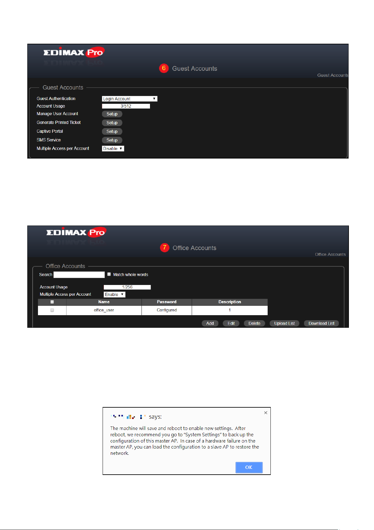
VII-6 Guest Accounts ............................................................................. 64
VII-6-1 Manage User Account .................................................................... 65
VII-6-2 Generate Printed Ticket ................................................................. 67
VII-6-3 Captive Portal ................................................................................. 69
VII-6-4 SMS Service .................................................................................... 72
VII-7 Office Accounts ............................................................................. 74
VII-7-1 RADIUS Authentication for Office Network under Win 7 .............. 76
VII-8 System Settings ............................................................................. 80
VII-8-1 LAN IP Address ............................................................................... 81
VII-8-2 System Settings .............................................................................. 83
VII-8-3 Management VLAN ID .................................................................... 86
VII-8-4 Save Settings to PC ......................................................................... 86
VII-8-5 Restore Settings from PC ............................................................... 87
VII-8-6 Master AP Firmware Upgrade ....................................................... 87
VII-8-7 Slave AP Firmware Upgrade........................................................... 88
VII-8-8 Firmware Upgrade (Slave-Only Interface) ..................................... 88
VII-9 E-MAPs .......................................................................................... 89
VII-9-1 Add / Edit Zone .............................................................................. 90
VII-9-2 Delete Zone .................................................................................... 92
VII-9-3 Show Map ...................................................................................... 92
VII-10 System Status .......................................................................... 98
VII-11 Advance Settings ................................................................... 104
VIII Advanced Settings ............................................................. 106
VIII-1 Dashboard ................................................................................... 106
VIII-1-1 System Information ..................................................................... 107
VIII-1-2 Devices Information ..................................................................... 107
VIII-1-3 Managed AP ................................................................................. 108
VIII-1-4 Managed AP Group ...................................................................... 110
VIII-1-5 Active Clients ............................................................................... 112
VIII-1-6 Active Users ................................................................................. 112
Page 4

VIII-2 Zone Plan .................................................................................... 112
VIII-2-1 Menu ............................................................................................ 114
VIII-2-2 Control ......................................................................................... 117
VIII-3 NMS Monitor .............................................................................. 119
VIII-3-1 Access Point ................................................................................. 119
VIII-3-1-1 Managed AP ..............................................................................................119
VIII-3-1-2 Managed AP Group ...................................................................................121
VIII-3-2 WLAN ........................................................................................... 124
VIII-3-2-1 Active WLAN ..............................................................................................124
VIII-3-2-2 Active WLAN Group ..................................................................................125
VIII-3-3 Clients .......................................................................................... 126
VIII-3-3-1 Active Clients .............................................................................................126
VIII-3-4 Users ............................................................................................ 127
VIII-3-4-1 Active Users ...............................................................................................127
VIII-3-4-2 Users Log ...................................................................................................127
VIII-3-5 Rogue Devices .............................................................................. 128
VIII-3-6 Information .................................................................................. 129
VIII-3-6-1 All Events/Activities ..................................................................................129
VIII-3-6-2 AP Monitoring ...........................................................................................130
VIII-3-6-3 SSID Overview ...........................................................................................132
VIII-4 NMS Settings ............................................................................... 133
VIII-4-1 Access Point ................................................................................. 134
VIII-4-1-1 Edit Access Point .......................................................................................135
VIII-4-1-1-1 Edit Basic Settings .............................................................................136
VIII-4-1-1-2 Edit Web Account Settings ................................................................137
VIII-4-1-1-3 Edit VLAN Settings .............................................................................138
VIII-4-1-1-4 Edit Radio Settings ............................................................................139
VIII-4-1-1-5 Edit WMM-EDCA Settings .................................................................142
VIII-4-1-1-6 Edit BandSteering Settings ................................................................142
VIII-4-1-1-7 Edit Profile Settings ...........................................................................143
VIII-4-1-1-8 Events.................................................................................................144
VIII-4-1-2 Add/Edit Access Point Group....................................................................145
VIII-4-1-2-1 Edit Basic Group Settings ..................................................................145
VIII-4-1-2-2 Edit Web Account Group Settings.....................................................146
VIII-4-1-2-3 Edit VLAN Group Settings .................................................................146
VIII-4-1-2-4 Edit Radio Group Settings .................................................................146
VIII-4-1-2-5 Edit WMM-EDCA Settings .................................................................149
Page 5

VIII-4-1-2-6 Edit BandSteering Settings ................................................................149
VIII-4-1-2-7 Edit Profile Settings ...........................................................................149
VIII-4-1-2-8 Edit Group Settings............................................................................150
VIII-4-2 WLAN ........................................................................................... 151
VIII-4-2-1 Add/Edit WLAN .........................................................................................152
VIII-4-2-2 Add/Edit WLAN Group ..............................................................................155
VIII-4-3 RADIUS ......................................................................................... 156
VIII-4-3-1 Add/Edit External RADIUS Server .............................................................157
VIII-4-3-2 Add/Edit Internal RADIUS Server .............................................................158
VIII-4-3-3 Add/Edit/Import/Export RADIUS Accounts .............................................159
VIII-4-3-4 Add/Edit RADIUS Group ...........................................................................162
VIII-4-4 Access Control .............................................................................. 163
VIII-4-4-1 Add/Edit MAC Access Control ..................................................................164
VIII-4-4-2 Add/Edit/Clone MAC Access Control Group ............................................165
VIII-4-5 Guest Network ............................................................................. 166
VIII-4-5-1 Add/Edit Guest Network ..........................................................................167
VIII-4-5-2 Add/Edit Guest Network Group ...............................................................170
VIII-4-6 Users ............................................................................................ 171
VIII-4-7 Guest Portal ................................................................................. 173
VIII-4-7-1 Free Guest Portal Type ..............................................................................174
VIII-4-7-2 User Level Agreement Guest Portal Type ................................................175
VIII-4-7-3 Static Users Guest Portal Type .................................................................176
VIII-4-7-4 Dynamic Users Guest Portal Type ............................................................177
VIII-4-7-5 External Captive Portal Guest Portal Type ...............................................179
VIII-4-7-6 Editing “Login Portal” ................................................................................180
VIII-4-8 Zone Edit ...................................................................................... 182
VIII-4-9 Schedule ....................................................................................... 184
VIII-4-10 Smart Roaming ............................................................................. 185
VIII-4-11 Device Monitoring ....................................................................... 187
VIII-4-12 Firmware Upgrade ....................................................................... 188
VIII-4-13 Advanced ..................................................................................... 189
VIII-4-13-1 System Security .........................................................................................189
VIII-4-13-2 Date & Time ...............................................................................................189
VIII-4-13-3 Google Maps .............................................................................................191
VIII-4-13-4 SMS ............................................................................................................192
VIII-5 Local Network ............................................................................. 194
VIII-6 Local Settings .............................................................................. 195
Page 6

VIII-6-1 Operation Mode .......................................................................... 195
VIII-6-2 Network Settings ......................................................................... 197
VIII-6-2-1 System Information ..................................................................................197
VIII-6-2-2 Wireless Clients .........................................................................................200
VIII-6-2-3 Wireless Monitor ......................................................................................201
VIII-6-2-4 Log ..............................................................................................................202
VIII-6-3 Management ................................................................................ 204
VIII-6-3-1 Admin ........................................................................................................204
VIII-6-3-2 Date and Time ...........................................................................................206
VIII-6-3-3 Syslog Server Settings ...............................................................................208
VIII-6-3-4 Syslog E-mail Settings ...............................................................................209
VIII-6-3-5 I’m Here .....................................................................................................210
VIII-6-4 Advanced ..................................................................................... 211
VIII-6-4-1 LED Settings ...............................................................................................211
VIII-6-4-2 Update Firmware ......................................................................................212
VIII-6-4-3 Save/Restore Settings ...............................................................................213
VIII-6-4-4 Factory Default ..........................................................................................214
VIII-6-4-5 Reboot .......................................................................................................215
VIII-7 Toolbox ....................................................................................... 216
VIII-7-1 Network Connectivity .................................................................. 217
VIII-7-1-1 Ping ............................................................................................................217
VIII-7-1-2 Trace Route ...............................................................................................218
VIII-7-1-3 IP Scan........................................................................................................219
IX Appendix ................................................................................ 220
IX-1 Configuring your IP address ........................................................ 220
IX-1-1 Windows XP ........................................................................................ 221
IX-1-2 Windows Vista ..................................................................................................223
IX-1-3 Windows 7 .........................................................................................................225
IX-1-4 Windows 8 .........................................................................................................229
IX-1-5 Mac ....................................................................................................................233
X FAQ ........................................................................................ 235
Page 7

OVERVIEW
The Edimax Office 1-2-3 is a complete and expandable Wi-Fi system designed
to meet the needs of small to medium offices. With easy setup, friendly
operation user interface, super-fast wireless speed, an extensive feature set
and a practical, ceiling-mount design, it is ideal for modern business
environments – in working areas, meeting rooms, lobby, or open spaces.
Office 1-2-3 Master includes a pre-configured Master Access Point
(expandable with Office +1 AP to up to a total of 16 APs), allowing a capacity
of up to 100 simultaneous users. The kit can setup multiple SSIDs (up to 32) to
suit different user environments such as departmental groups or user groups.
A built-in RADIUS server provides additional verification with a scalable AP
array architecture, as well as a centralized management system for multiple
access points. Power over Ethernet (PoE) support allows for deployment
flexibility and extensive network options for company MIS departments and
network administrators.
*There can be only one Office 1-2-3 master unit on the network. The
additional AP should be Office +1.
1
Page 8

I Quick Summary & Reminder
1. You can find all supporting documents, video, and programs, we advise
you to upgrade to the latest firmware first:
http://office123.edimax.com
2. If you connect extra Office +1 APs during initial power up, please wait
10 minutes for APs to communicate with each other.
3. Download our IP Finder from the link below to search and find the
master AP for configurations.
www.edimax.com/edimax_pro/download/IPfinder
4. To setup Office 1-2-3 using a mobile device, IP Finder mobile app can
be downloaded and used. Please III-2 Initial Setup – Mobile Device
below.
5. If you are unable to load IP Finder: Right-click on the IP Finder and
choose “Property”. Click Unblock on the bottom selection and click
“OK”.
6. The default username and password are admin and 1234 respectively.
Changing password on the Master AP will also change the password of
the Slave APs.
7. It is recommended that you use the default settings whenever possible.
Refer to later sections of this manual for more information on the
settings
8. It is recommended to use import and export list for simple
management of guest and office accounts.
2
Page 9

9. When configuring, please check for a “Progress Circle” on the upper
right hand side of the page. Please wait until the progress circle is
finished before further configurations.
10. The RADIUS function used by Office network works directly with most
OS except Windows versions older than Win 8.0. For instructions on
setting up RADIUS function, please refer to 1) VII-7-1 RADIUS
Authentication for Office Network under Win 7 on page 76; 2) the
included A4 Sheet; or 3) download “RADIUS Authentication for Office
Network” from the link:
www.edimax.com/edimax_pro/download/Office1-2-3
11. This product supports multiple devices per login account.
12. Clicking Apply during any of the configuration will reboot the AP, which
takes time, it is recommended that you use Apply only after changing
all settings.
13. Should you connect to the guest network, open a browser to trigger
the login page. If no login page is shown, try entering
www.edimax.com.
14. A maximum of 128 Guest accounts and 256 Office accounts are
supported. Multiple logins (of the same account/password) are
accounted as using multiple accounts.
15. The frontdesk account is for creation of guest accounts only. It cannot
make changes to other settings.
16. To connect Office 1-2-3 to your VLAN Network, Management VLAN ID
(under System Settings) must be configured to be the same as the one
on your switch. All the wireless SSID and LAN can only share one VLAN
ID. It is recommended to put the AP on the VLAN that can access both
3
Page 10

LAN and Internet network. The Guest network in Office 1-2-3 can
prohibit guest accessing the Intranet network by IP filtering.
17. If you wish to add more APs to expand your office coverage, please
consult your representative and refer to the “Office +1 AP” package.
4
Page 11

II Product Information
1. Office 1-2-3 Master Access
Point
2. Ceiling Mount Bracket
3. T-Rail Mounting Kit & Screws
4. CD
5. Quick Installation Guide
6. Ethernet Cable
7. Power Adapter
8. Ceiling Mount Screw Template
7
8 5 6 4 1 2 3
II-1 Package Contents
Product Information
5
Page 12
II-2 System Requirements
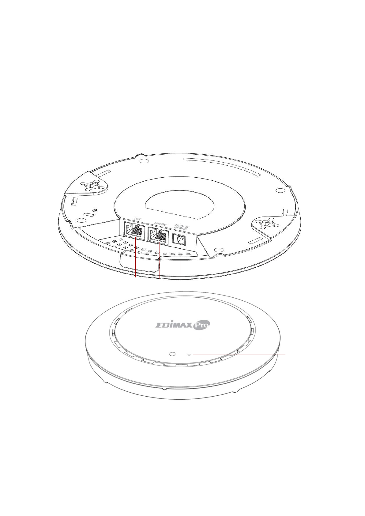
A
12V DC IN
12V DC port to connect the power adapter
B
LAN 1 (PoE)
LAN port with Power over Ethernet (PoE) IN
C
LAN 2
LAN port
D
Reset
Resets the device to factory default settings
A
B
C
D
- Existing cable/DSL modem & router.
- Existing PoE Switch connected to the router
- Computer with web browser for access point configuration
II-3 Hardware Overview
Product Information
6
Page 13
II-4 LED Status
LED Color
LED Status
Description
Blue
On
The access point is on.
Flashing Slowly
Upgrading firmware.
Flashing Quickly
Resetting to factory defaults.
Amber
On
Starting up.
Flashing
Error.
Off
Off
The access point is off.
NOTE: You may need to use a pin or similar sharp object to push the
reset button.
II-5 Reset
Product Information
If you experience problems with your access point, you can reset the device
back to its factory settings. This resets all settings back to default.
1. Press and hold the reset button on the access point for at least 10
seconds then release the button.
2. Wait for the access point to restart. The access point is ready for setup
when the LED is blue.
7
Page 14

Quick Setup
III Quick Setup
This quick setup is a guide to setting up your Office 1-2-3 high speed Wi-Fi
network. Please note that these sections can be revisited later on for further
configurations, but will serve as the basics of the system.
III-1 Initial Setup – Computer
The computer initial setup is a simple step-by-step process to start up the web
user interface. Please follow the steps below:
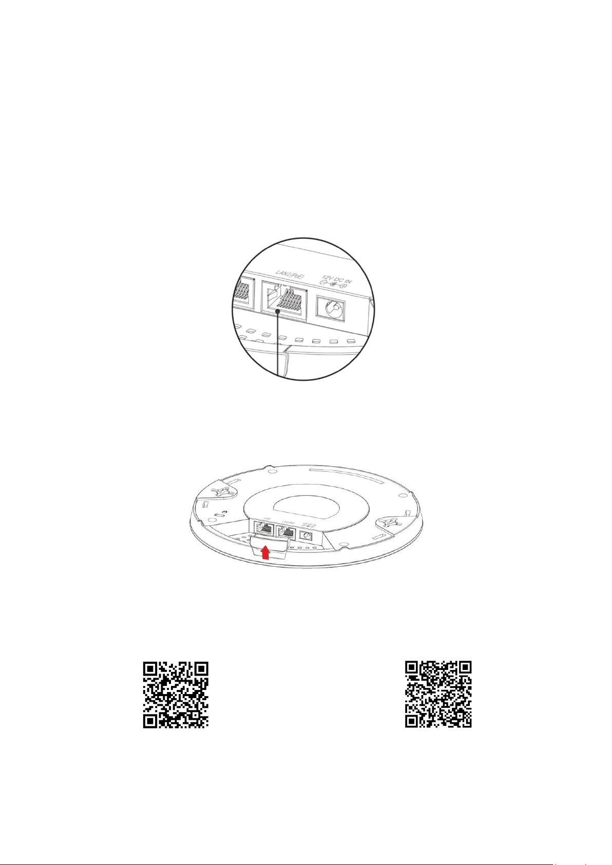
1. Connect your computer to the PoE Switch using an Ethernet cable.
2. Connect the access point to the PoE Switch using the included Ethernet
cable. Please make sure the Ethernet cable is connected to the PoE port
of the access point as shown below:
If you need to, remove the cap from the underside of the access point.
This creates extra space for cables to pass through.
8
Page 15
Quick Setup
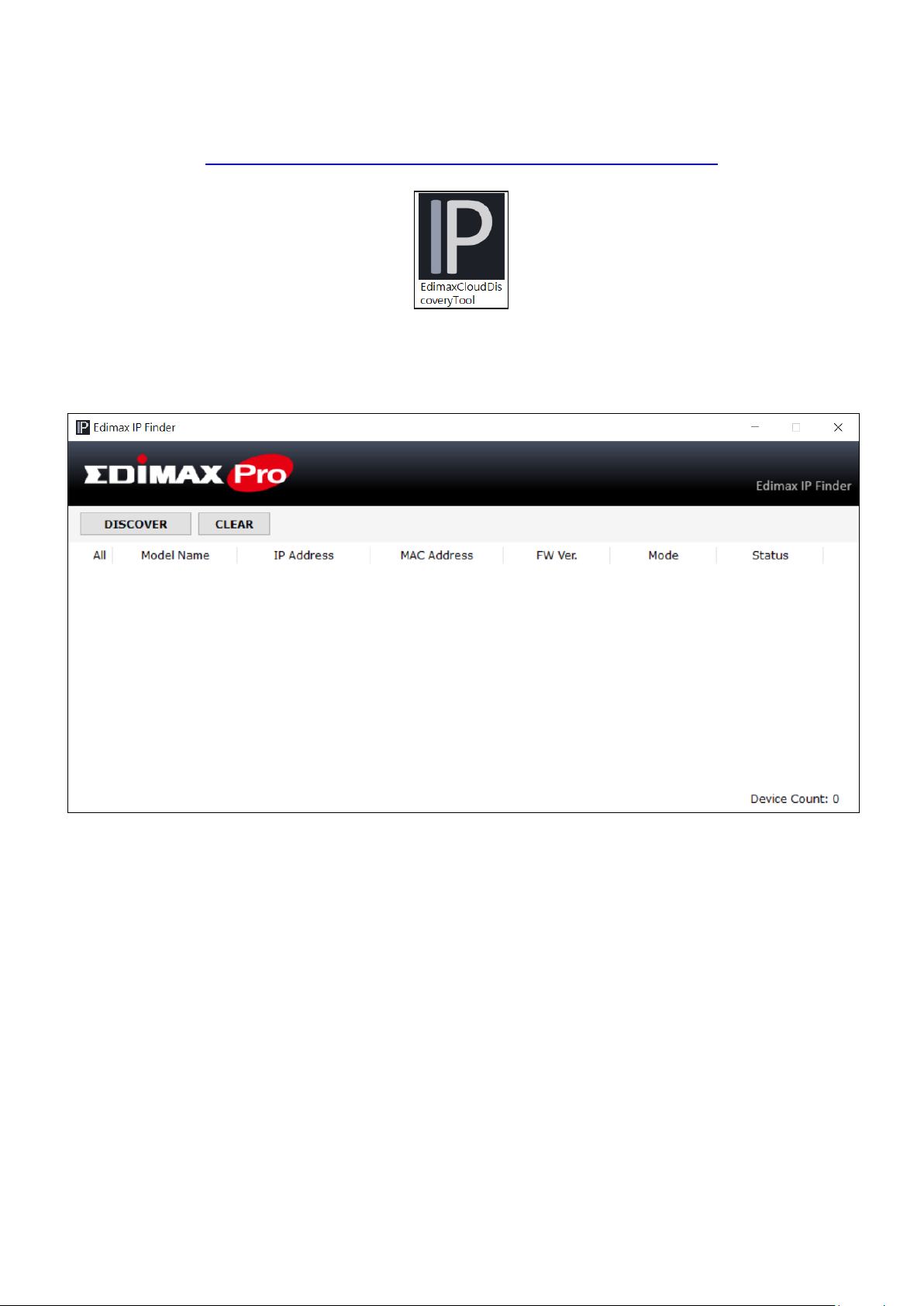
3. Download and Install the Edimax Cloud Discovery Tool (IP Finder) on
your computer from the link below:
www.edimax.com/edimax_pro/download/IPfinder
4. Open the “EdimaxCloudDiscoveryTool”:
9
Page 16
Quick Setup
Unable to open IP Finder Tool
If you were unable to open the IP Finder Tool, it may be because the
antivirus on your system is blocking it. To unblock, please see below:
1. Right-click on the IP Finder
tool and click “Properties”
2. Locate “Security” at the bottom of
the window. Click the Unblock
button.
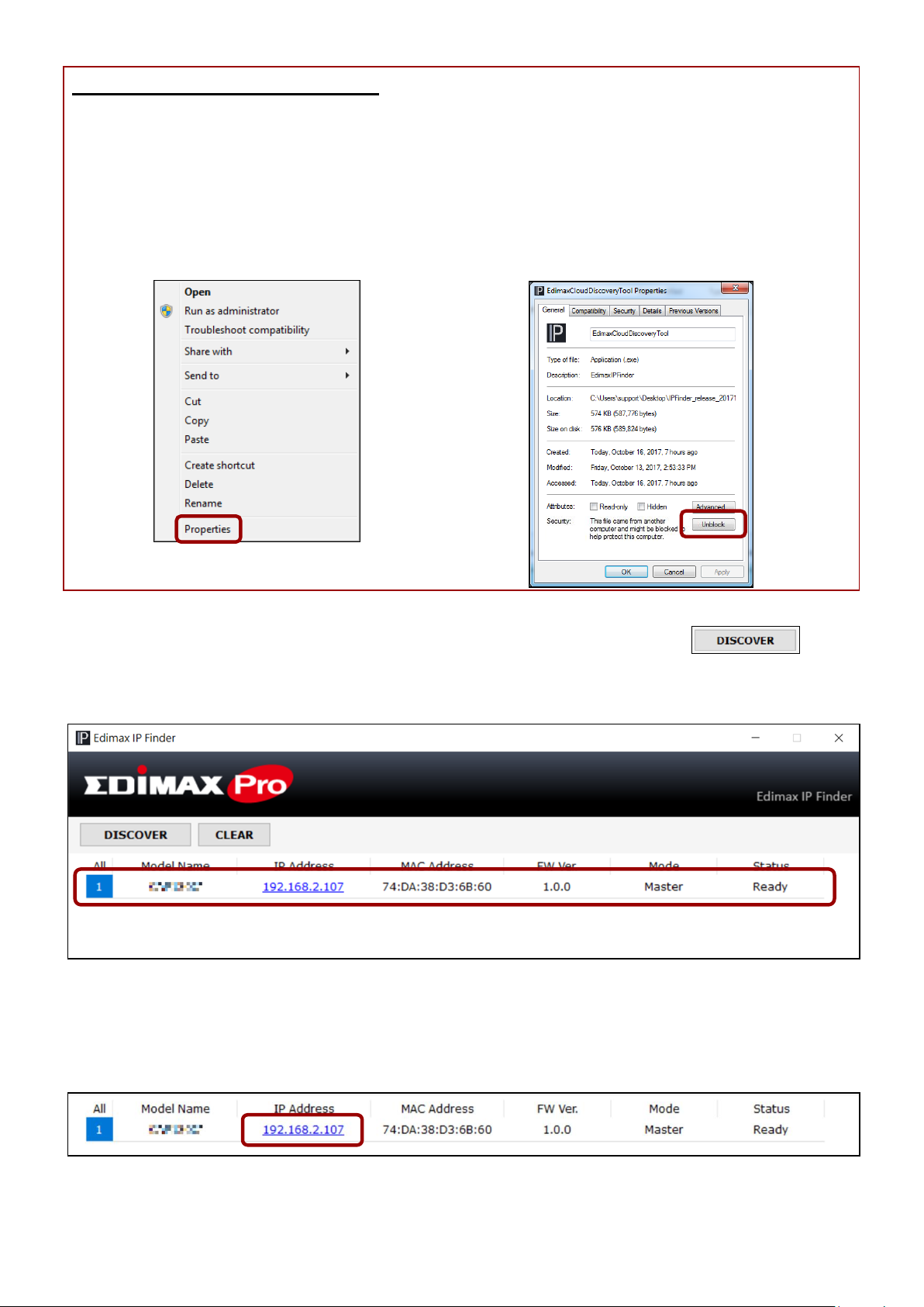
5. Locate your master access point by clicking “Discover” on
the IP finder.
6. Click the IP address of the master access point to go into the web user
interface.
10
Page 17
Quick Setup
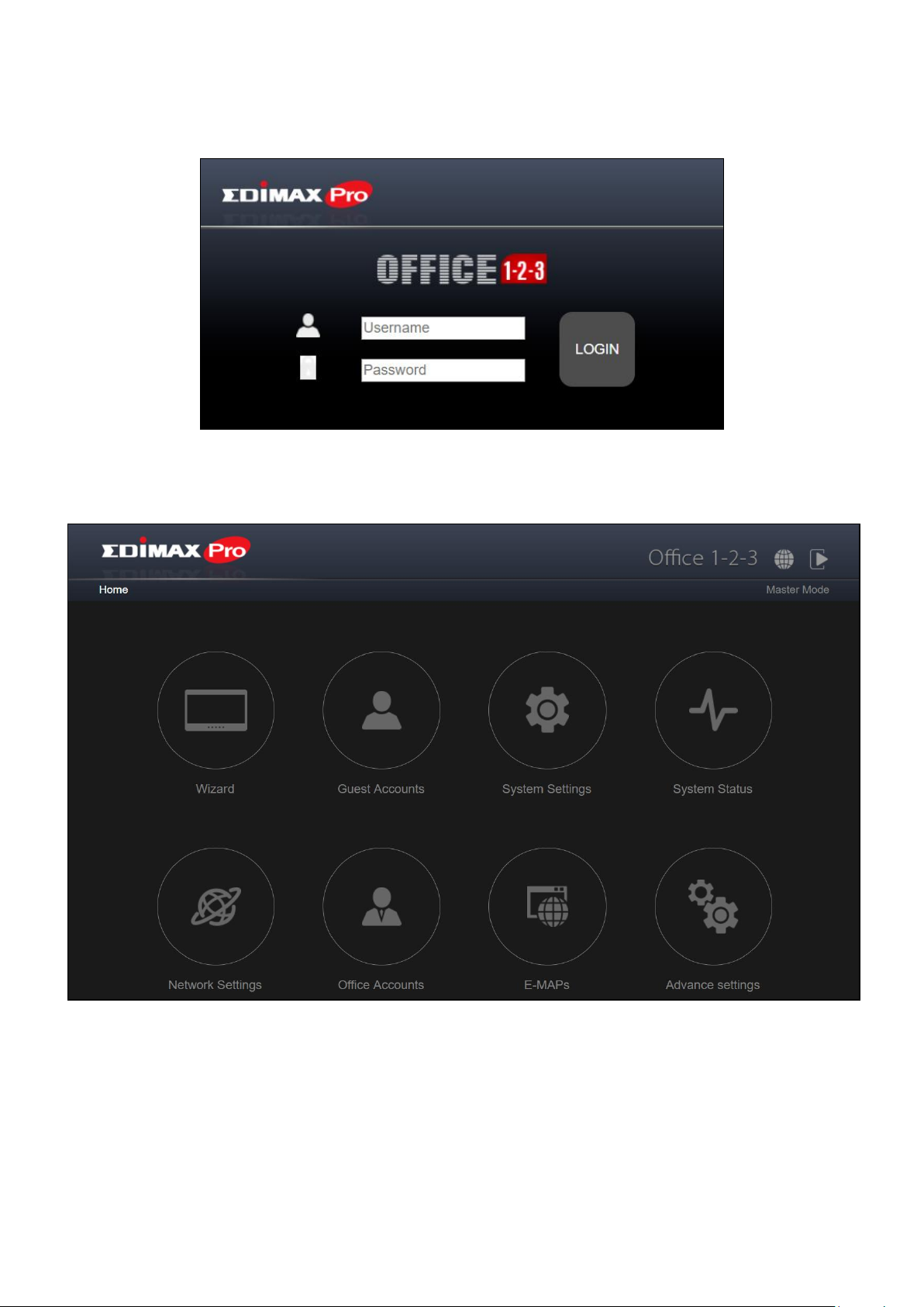
Upon entering the webpage, you should be prompted to enter the username
and password, enter them (default username: admin, password: 1234) to
proceed:
The web user interface is shown below:
7. Click “Wizard” and go to the next section to go through the setup
wizard.
11
Page 18
Quick Setup
iOS
Android
III-2 Initial Setup – Mobile Device
The initial setup for mobile device is a simple step-by-step process to start up
the mobile web user interface.
1. Connect the access point to the PoE Switch using the included Ethernet
cable. Please make sure the Ethernet cable is connected to the PoE port
of the access point as shown below:
If you need to, remove the cap from the underside of the access point.
This creates extra space for your cables to pass through.
2. Please scan the QR Code below to download the mobile app
“Office123”.
3. On your mobile device, connect to the device network. The device
network SSID is “device”.
12
Page 19
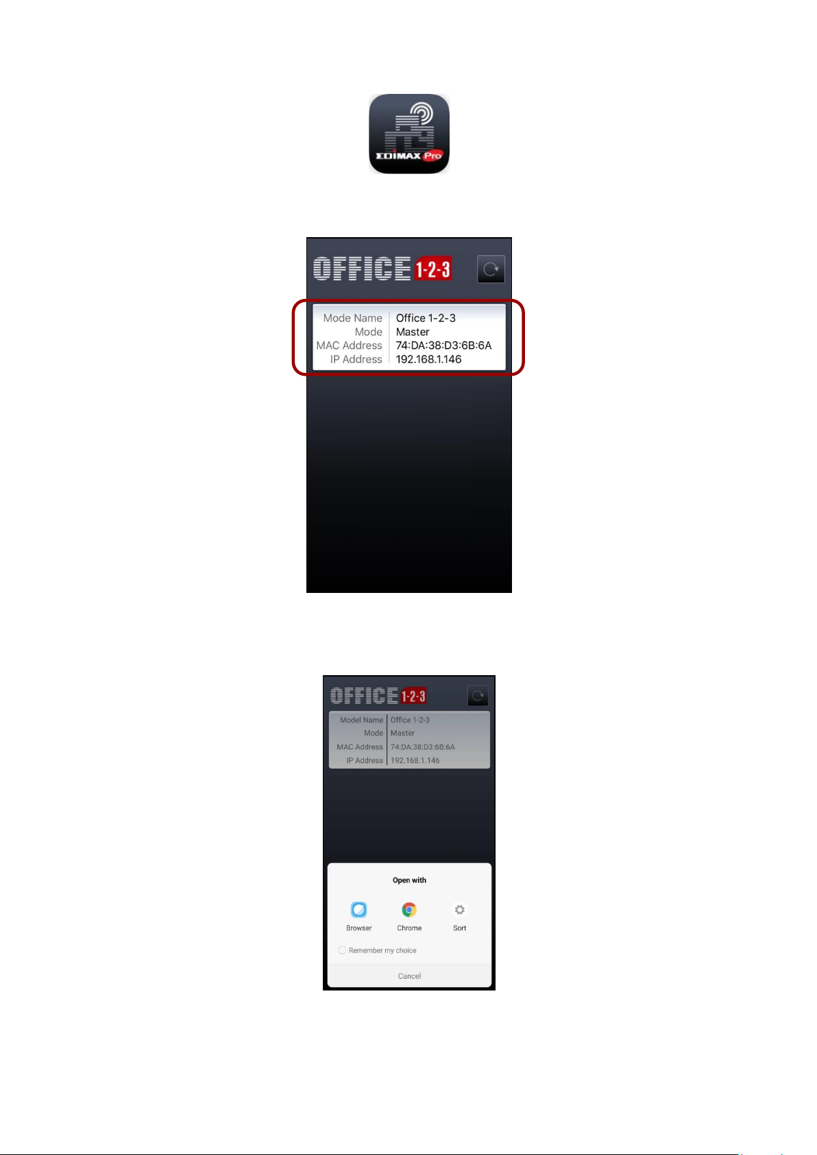
4. Open the “Office123” app.
5. Locate the Master AP and tap it.
Quick Setup
The system may prompt you to select a desired browser as shown
below:
13
Page 20
Quick Setup
NOTE: Please remember to assign a WPA-PSK2 password to the
Device Network later to prevent others from accessing the network
freely.
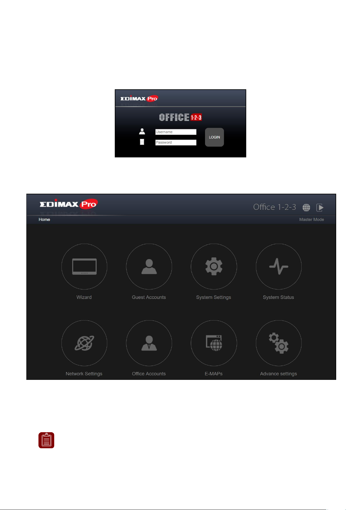
6. The browser will be at the login page of Office 1-2-3.
Upon entering the webpage, you should be prompted to enter the username
and password, enter them (default username: admin, password: 1234) to
proceed:
The web user interface is shown below:
7. Tap “Wizard” and go to the next section to go through the setup
wizard.
14
Page 21
Quick Setup
NOTE: In most cases, simply go through the steps below by clicking
“Next”, although adding / editing password, Wi-Fi-key, and accounts
are recommended.
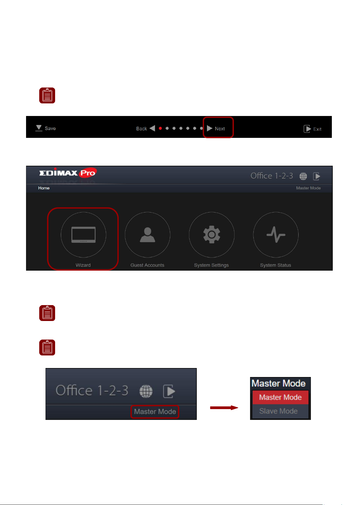
NOTE: The Frontdesk account is for creating guest accounts and
ticket printing only.
NOTE: You can change between master and slave modes at will by
clicking the current mode (outlined area below). It is, however, not
recommended except for the recovery of master AP.
III-3 Setup Wizard
The wizard aims to help you with setting the basic settings of the Office 1-2-3
network including Office Accounts, Guest Accounts and Device Network, etc.
1. Click “Wizard” on the web interface to start the setup wizard:
2. Change the password for Administrator and Frontdesk account.
15
Page 22
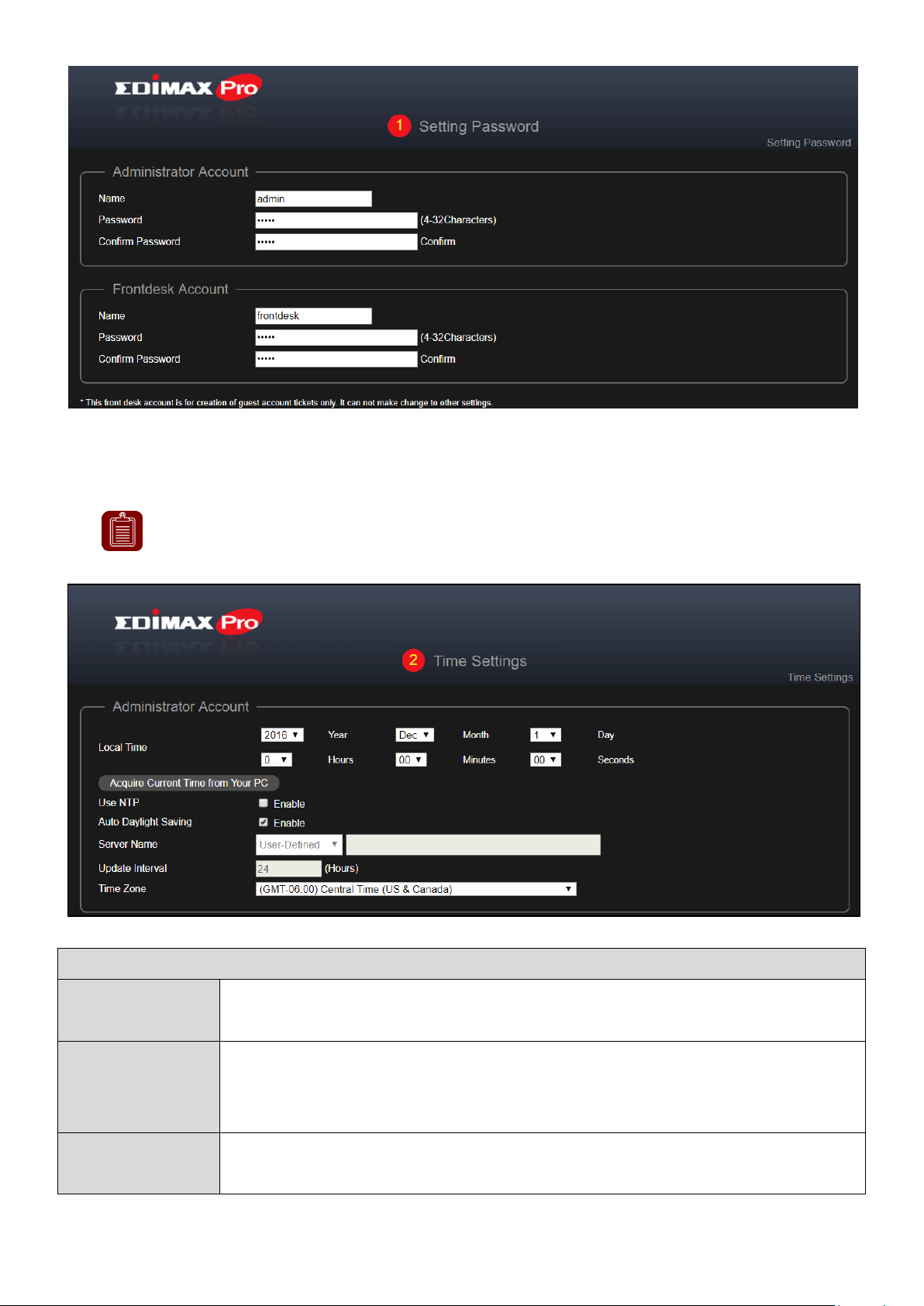
NOTE: It is highly recommended to turn on the NTP server so the
device can remain on time even after power recycling. Choose an
NTP server that is close to your country.
Date and Time Settings
Local Time
Set the system’s date and time manually using the drop down
menus.
Acquire
Current Time
from your PC
Click to acquire time and date automatically from your PC.
Use NTP
Check to enable automatic time and date sync to an NTP
server.
3. Time Settings: Set the time of your access point.
Quick Setup
16
Page 23
Auto Daylight
Saving
Check / uncheck to enable / disable daylight saving function.
Server Name
Use the drop down menu to select a region. A server will be
shown after selecting the region. Choose the region according
to your location.
Update
Interval
Specify how often (in hours) the access point synchronizes
with the NTP server.
Time Zone
Select the time zone of your country/region. If your
country/region is not listed, please select another
country/region whose time zone is the same as yours.
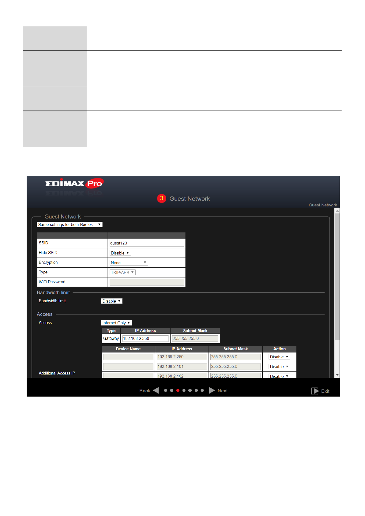
4. Guest Network: Configure the guest network settings
Quick Setup
For more information on the settings, please refer to VII-5-5 Guest Network on
page 61.
Press “Next” to continue.
17
Page 24
Quick Setup
NOTE: It is recommended to leave the settings as it is (default
values).
NOTE: It is recommended to only change the Wi-Fi password.
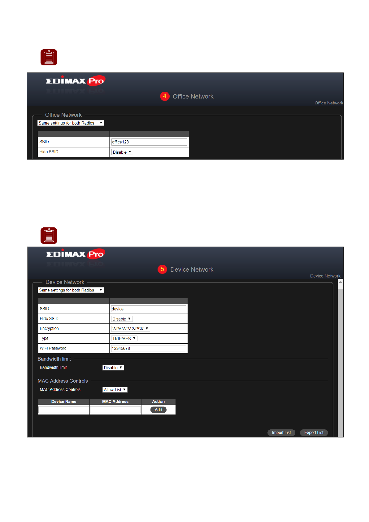
5. Office Network: Configure the office network settings.
For more information on the settings, please refer to VII-5-2 Office Network on
page 54.
Press “Next” to continue.
6. Device Network: Configure the device network settings.
Select WPA-PSK2 for encryption field and enter a Wi-Fi Password.
For more information on the settings, please refer to VII-5-3 Device Network on
page 56.
Press “Next” to continue.
18
Page 25
Quick Setup
7. Guest Accounts: Configure the guest account settings.
For more information on the settings, please refer to VII-6 Guest Accounts on
page 64.
Press “Next” to continue.
8. Office Accounts: Configure the Office Accounts settings.
For more information on the settings, please refer to VII-7 Office Accounts on
page 74.
Press “Next” to continue.
9. Click “Save & Exit” to complete the wizard.
An advice message will be shown before saving and rebooting:
19
Page 26

Click “OK” to continue (with message shown below):
10. Please wait a moment for the AP to reboot.
Quick Setup
20
Page 27

Further Expansion
IV Further Expansion
The Office 1-2-3 Master is a pre-configured and self-managed access point.
Expansion is very easy with additional Office 1-2-3 Access Points (available as
Office +1 AP) of up to 16 access points in total.
The Office 1-2-3 Master will manage other connected Office 1-2-3 APs where
they are automatically designated as Managed APs (slaves).
21
Page 28
Hardware Installation / Deployment
V Hardware Installation / Deployment
If you plan to add more Office +1 APs, a quick deployment guide is shown
below:
V-1 Office 1-2-3 Deployment
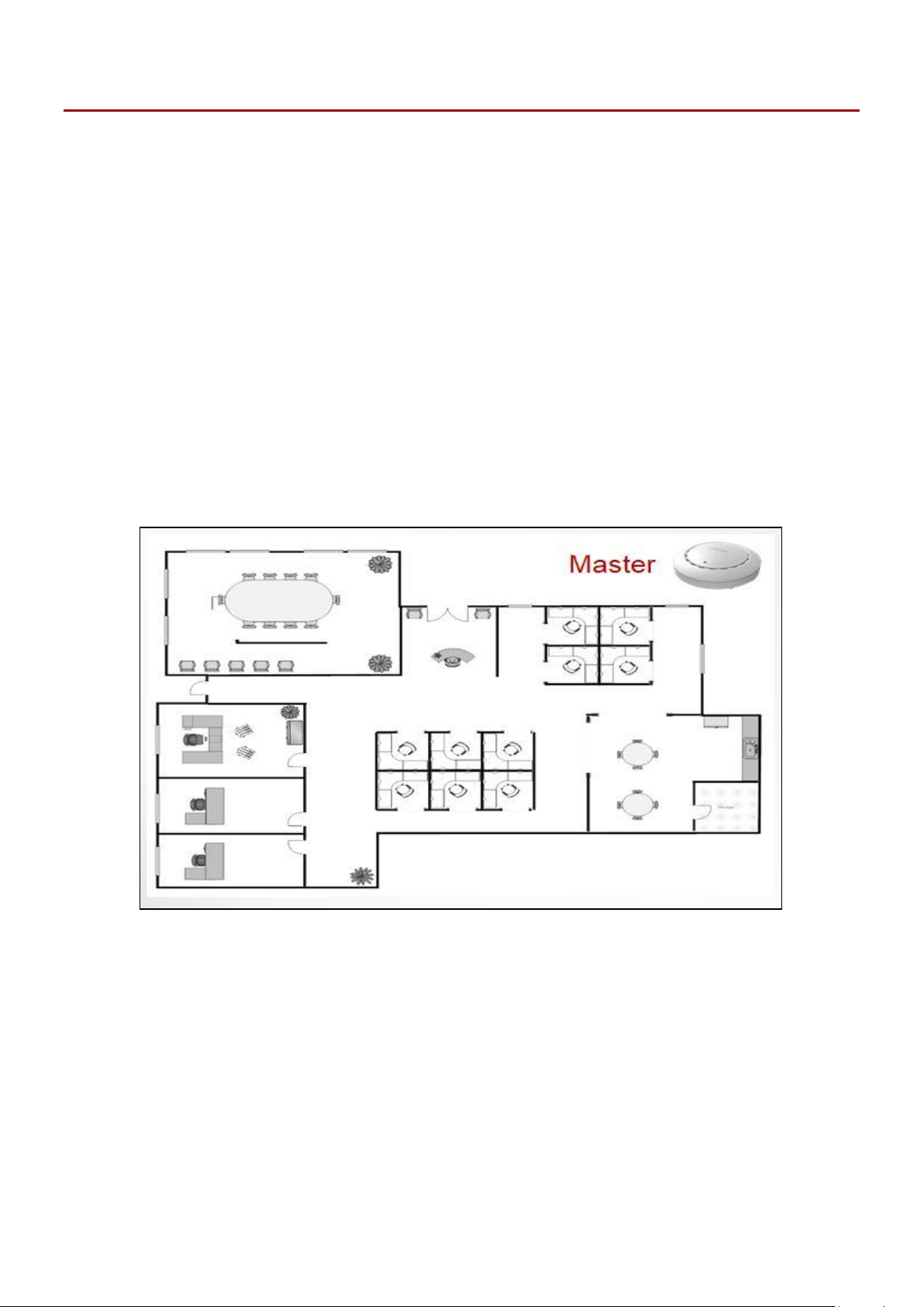
1. Install the Master AP in a less crowded area.
This will reduce the loading of the Master AP. Due to the fact that the
Master AP being the controller of the network, having reduced loading
will benefit. For example, you can install the Master AP in a corner of
your office, where there will be less users attempting to connect to it.
22
Page 29
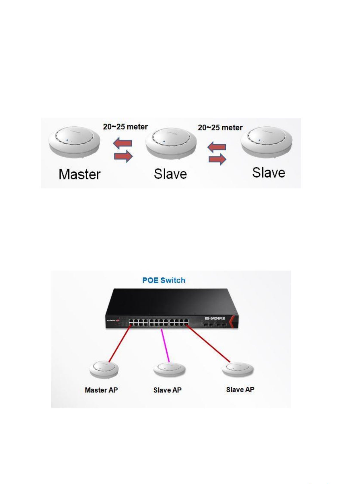
2. Install the slave APs in more crowded areas.
Since the APs will only be extending the Wi-Fi signals (no need to
manage the network), they can be installed where connections are in
greater demand.
The distance between the Master AP and the Slave APs is
recommended to be between 20-25 meters.
Hardware Installation / Deployment
3. Install Master/Slave AP Hardware on the POE switch.
Connect a PoE switch to the Master and Slave AP’s LAN 1 (PoE) port
using an Ethernet cable.
23
Page 30
Hardware Installation / Deployment
A
A
B B C
C
D
D
E E F
F
V-2 Mounting
When deployment plan is sorted, please refer to the instructions below on
how to mount each of your Office 1-2-3 Access Points.
V-2-1 Wooden Ceiling
Please refer to the figure below:
24
Page 31

Hardware Installation / Deployment
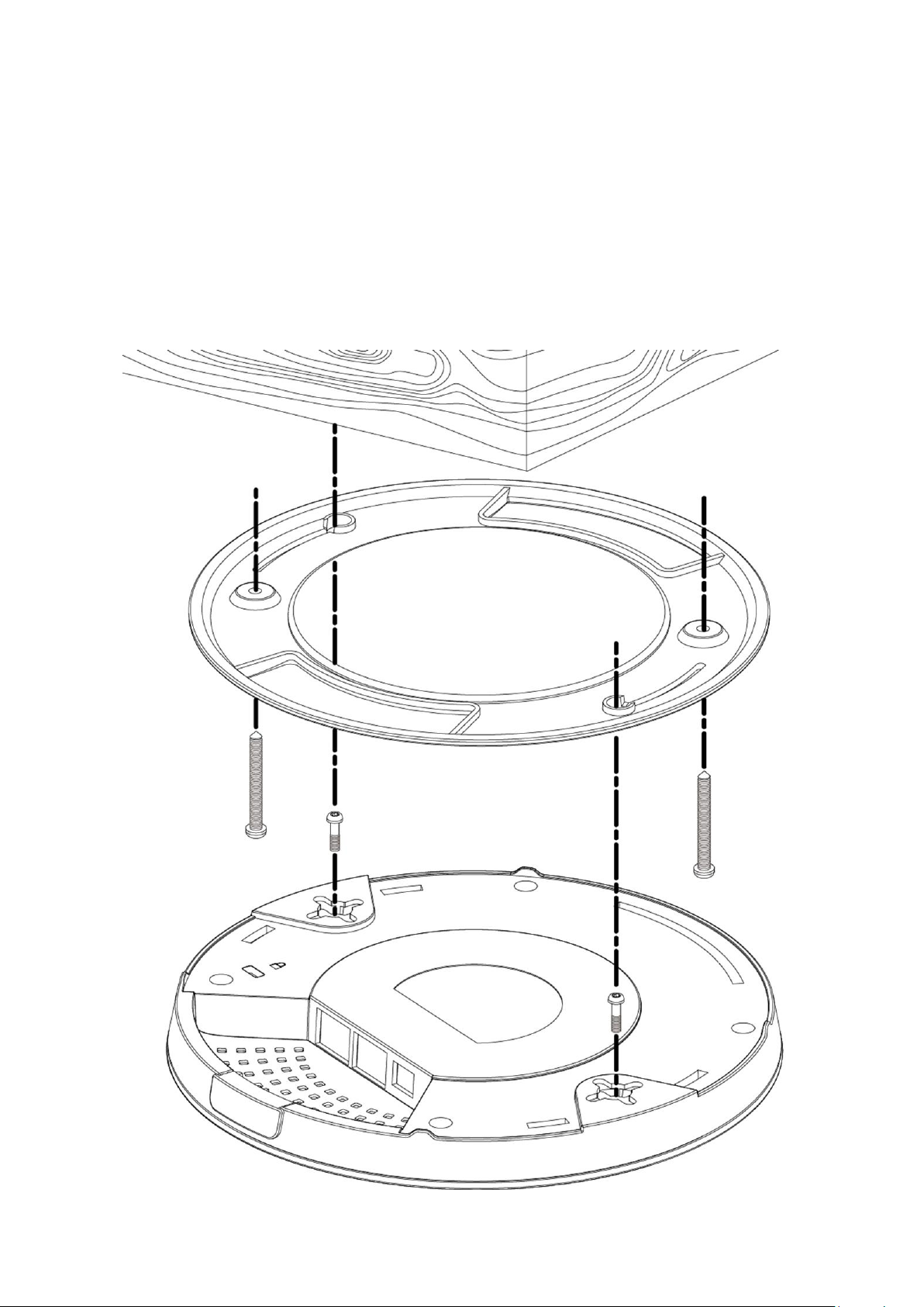
1. By using the holes A on the ceiling bracket, identify and mark correct
screw positions of the desired mounting location.
2. Where necessary, drill a hole (of radius smaller than the radius of the
provided screws) on each of the marked screw positions.
3. Fix the ceiling mount bracket to the desired location by inserting the
ceiling fixing screws B through the bracket ceiling holes A. Tighten the
ceiling fixing screws B to the marked screw position using a screw driver
to fix the bracket in place.
4. Fix the bracket rail screws C into the holes D on the device using a
screw driver. The cap of the screws should be protruding outwardly
from the holes D.
5. Insert the bracket rail screws C into the device fixing holes E.
6. Twist the device as the bracket rail screws C slide through the bracket
rail F.
Twist the device all the way until you feel that it is fixed in position.
25
Page 32

V-2-2 Other Ceiling
E
G
G
E A A F F B B
C C D
D
Please refer to the figure below:
Hardware Installation / Deployment
1. By using the holes A on the ceiling bracket, identify and mark correct
screw positions of the desired mounting location.
2. Where necessary, drill a hole on each of the marked screw positions.
26
Page 33

Hardware Installation / Deployment
3. Insert the anchors G into the holes (use a screw driver where necessary)
at the marked screw positions.
4. Fix the ceiling mount bracket to the desired location by inserting the
ceiling fixing screws B through the bracket ceiling holes A. Tighten the
ceiling fixing screws B onto the anchors G using a screw driver to fix the
bracket to the ceiling.
5. Fix the bracket rail screws C into the holes D on the device using a
screw driver. The cap of the screws should be protruding outwardly
from the holes D.
6. Insert the bracket rail screws C into the device fixing holes E.
7. Twist the device as the bracket rail screws C slide through the bracket
rail F.
Twist the device all the way until you feel that it is fixed in position.
27
Page 34

Hardware Installation / Deployment
A A C C B
B
D A A
V-2-3 T-Rail Mount
To mount the device to a T-Rail, please follow the instructions below and refer
to the diagrams below.
1. Select the correct size T-Rail bracket included in the package contents.
2. Attach the selected T-Rail brackets A to holes B using bracket fixing
screws C.
28
Page 35

Hardware Installation / Deployment
E E A
A
3. Clip the device onto the T-Rail D using the now attached T-Rail brackets
A.
If you need more space between the device and the T-Rail, additional
cushion bracket E can be added between T-Rail brackets A and holes B
(use the longer screws included).
29
Page 36

Hardware Installation / Deployment
NOTE: there can only be ONE Master AP inside your network. Use
this procedure only if your master AP is down and need a
replacement.
Reminder:
Download and Install the Edimax Cloud Discovery Tool (IP Finder) on your
computer from the link below:
www.edimax.com/edimax_pro/download/IPfinder
If you are unable to open the IP Finder Tool, please refer to the included IP
Finder document in the Office 1-2-3 Kit Box or III-1 Initial Setup – Computer.
VI Replacing Master AP
This section will be a step-by-step procedure guiding you through replacing
the original Master AP, where you will be upgrading the replacement AP to
the Master AP’s firmware, followed by recovering previously saved system
settings.
Please make sure you have:
- The Master AP firmware (downloadable from Edimax website)
- The Master AP’s settings (backed up from the system on a regular basis)
1. Open the “EdimaxCloudDiscoveryTool”:
30
Page 37

Hardware Installation / Deployment
2. Locate your Office +1 AP by clicking “Discover” on the IP
finder.
3. Click the IP address of the access point designated to be the master AP
and go into the web user interface.
31
Page 38

Hardware Installation / Deployment
Upon entering the webpage, you should be prompted to enter the username
and password, enter them (default username: admin, password: 1234) to
proceed:
The web user interface is shown below:
32
Page 39

Hardware Installation / Deployment
4. Click on “System Settings” icon.
Upgrading Firmware
5. Scroll down to the bottom of the page to find “Firmware Upgrade”.
If you haven’t already, please go to the URL link below to download the
newest Master firmware:
www.edimax.com/edimax_pro/download/Office1-2-3
Locate the Master firmware and click on the download icon to download.
6. Click “Choose File” to select the master firmware file.
7. Click “Update” to update the unit to the master firmware version. The
system will ask you whether to continue, click “OK”.
33
Page 40

Hardware Installation / Deployment
A reminder message will be displayed, click “OK” to continue.
The system will be updating, please wait…
8. After the firmware upgrade, the system will prompt you to enter the
username and password, enter them (default username: admin,
password: 1234) to proceed:
9. The system is still in slave mode, click on the outlined “Slave Mode”
icon and click “Master Mode”:
34
Page 41

Hardware Installation / Deployment
More system message will be displayed, click “OK” to continue”
The system is now rebooting, please wait…
10. After the firmware upgrade, the system will prompt you to enter the
username and password again, enter them (default username: admin,
password: 1234) to proceed:
The Master AP web user interface will be displayed:
35
Page 42

11. Click on “System Settings” icon.
Restore Previous Settings
Hardware Installation / Deployment
12. Scroll down to find “Firmware Upgrade”.
13. Click the “Choose File” button to find a previously saved settings file on
your computer.
14. Click “Restore” to replace your current settings.
If your settings file is encrypted with a password, check the “Open file with
password” box and enter the password in the following field.
The system will show that restoring the settings is complete and is rebooting:
Congratulations! You have successfully replaced the previous Master AP!
36
Page 43

Office 1-2-3 Interface
VII Office 1-2-3 Interface
Office 1-2-3 offers friendly interface that are easy to use and intuitive for
administrators.
VII-1 IP Finder
IP Finder is a tool to help you discover Office 1-2-3 Access Points currently
connected to your network. It will display the Access Points’ IP Addresses,
MAC Addresses, Firmware Version, Current Mode and Current Status.
- Download and Install the Edimax Cloud Discovery Tool (IP Finder) on your
computer from the link below:
www.edimax.com/edimax_pro/download/IPfinder
- Once downloaded, double-click the file to open the tool. The finder
interface is as shown below:
37
Page 44

Office 1-2-3 Interface
Unable to open IP Finder Tool
If you were unable to open the IP Finder Tool, it may be because the antivirus
on your system is blocking it. To unblock, please see below:
1. Right-click on the IP Finder
tool and click “Properties”
2. Locate “Security” at the bottom of the
window. Click the Unblock button.
Discover
Clicking the button will display all Access Points in your network.
Enter Office 1-2-3 Setup Page
Clicking on the IP Address of an Access Point allows you to go into its setup
page.
38
Page 45

Office 1-2-3 Interface
NOTE: You can change between master and slave modes at will by
clicking the current mode (outlined area below). It is, however, not
recommended except for the recovery of master AP.
A B C
D
VII-2 Home
This is the dashboard or home of the Office 1-2-3 Master interface.
To select the mode of the access point, click A and select the mode:
39
Page 46

Office 1-2-3 Interface
To log out of the web user interface, click (or B).
To select a different language, click (or C) and select the language of
the interface:
If you wish to return to this home page during any of the navigation through
the interface, click (or D) to return home.
40
Page 47

Office 1-2-3 Interface
Wizard
Network Settings
Guest Accounts
Office Accounts
System Settings
E-Maps
System Status
Advanced Settings
VII-3 Wizard
Click the “Wizard” icon to go through the setup wizard of office 1-2-3. Refer
to III-3 Setup Wizard on the setup process.
VII-4 Navigation
When using the user interface, navigation can also be achieved by selecting
the navigation icons on the left, as demonstrated below:
41
Page 48

Office 1-2-3 Interface
VII-5 Network Settings
This is the general network settings of your Office 1-2-3 system. You can
Manage APs, Manage AP group, configure Office Network, Device Network,
Guest Network and setup a Wireless Schedule for your system.
Click the “Network Settings” icon.
42
Page 49

VII-5-1 Manage AP
Click the “Manage AP” icon.
Office 1-2-3 Interface
This page displays information about each Managed AP in the local network:
Index (reference number), Mode, Device Name (MAC Address), Model, IP
Address, No. of Clients connected to each access point, Status, and Actions.
Click the “Refresh” button to refresh the managed AP list.
43
Page 50

Office 1-2-3 Interface
Status Icons
Icon
Color
Status
Definition
Grey
Disconnected
Managed AP is disconnected. Please check
the network connection and ensure the
Managed AP is in the same IP subnet as the
Master AP.
Red
Authentication
Failed
Or
Incompatible
AP Version
System security must be the same for all
access points in the AP array. Please check
security settings.
All access points must have the same
firmware version. Please use the Master
AP’s firmware upgrade function.
Orange
Configuring or
Upgrading
Please wait while the Managed AP makes
configurations or while the firmware is
upgrading.
Yellow
Connecting
Please wait while the Managed AP is
connecting.
Green
Connected
Managed AP is connected.
Blue
Waiting for
Approval
Managed AP is waiting for approval. Note:
Up to 15 Managed APs are supported.
Additional APs will have this status until an
existing Managed AP is removed.
Click the “Edit” button to edit the checked AP’s settings (see Edit below).
Click the “Group Edit” button to edit the group settings (see Group Edit
below).
Click the “Delete” button to delete the checked AP(s).
The Status icon displays the status of each Managed AP.
44
Page 51

Office 1-2-3 Interface
Each Managed AP has “Action” icons with the following functions:
1. Disallow
Remove the Managed AP from the AP array and disable connectivity.
2. Edit
Edit various settings for the Managed AP (see Edit below).
3. Blink LED
The Managed AP’s LED will flash temporarily to help identify & locate
access points.
4. Buzzer
The Managed AP’s buzzer will sound temporarily to help identify & locate
access points.
5. Network Connectivity
Go to the “Network Connectivity” panel to perform a ping or traceroute.
6. Restart
Restarts the Managed AP.
45
Page 52

Office 1-2-3 Interface
VII-5-1-1 Edit Managed AP
To Edit a managed AP, either 1) check the checkbox of said AP, and click the
“Edit” button;
Or 2) click the Edit icon.
Click “Save” to save the settings. Click “Cancel” to forfeit the changes. Click
“Save and Apply” to save and apply the settings.
VII-5-1-1-1 Basic Settings
If the AP is a member of an AP Group and you wish to use a different setting
than the AP Group setting, check “Override Group Setting” for the options /
fields to turn white to allow adjustments.
46
Page 53

Office 1-2-3 Interface
Basic Settings
Name
Edit the access point name. The default name is AP + MAC
address.
Description
Enter a description of the access point for reference e.g. 2nd
Floor Office.
MAC Address
Displays MAC address.
IP Address
Assignment
“DHCP Client” or “Static IP Address” are the two options.
Select “DHCP Client” for automatic assignment of a dynamic
IP address from your router’s DHCP server.
Select “Static IP Address” to manually specify a static/fixed IP
address for your access point.
IP Address
If “Static IP Address” is selected in the option above, specify
an IP address in the field. This IP address will be assigned to
your access point and will replace the default IP address.
If “DHCP Client” is selected, no entry will be required.
Subnet Mask
If “Static IP Address” is selected in the option above, specify a
subnet mask. The default value is 255.255.255.0.
If “DHCP Client” is selected, no entry will be required.
Default
Gateway
For DHCP users, select “From DHCP” to get default gateway
from your DHCP server or “User-Defined” to enter a gateway
manually. For static IP users, the default value is blank.
DHCP users can select “From DHCP” to get default gateway
from DHCP. No entry will be required.
Select “User-Defined” to manually enter a value.
If “Static IP Address” is selected in the option above, enter a
value in the field that follows.
Primary DNS
DHCP users can select “From DHCP” to get primary DNS
server’s IP address from DHCP. No entry will be required.
Select “User-Defined” to manually enter a value.
If “Static IP Address” is selected in the option above, enter a
value in the field that follows.
Secondary
DNS
DHCP users can select “From DHCP” to get secondary DNS
server’s IP address from DHCP. No entry will be required.
Select “User-Defined” to manually enter a value.
If “Static IP Address” is selected in the option above, enter a
value in the field that follows.
47
Page 54

Office 1-2-3 Interface
IGMP
Snooping
Enable / Disable the IGMP Snooping function.
IGMP snooping is the process of listening to Internet Group
Management Protocol (IGMP) network traffic.
Radio Settings
Wireless
Enable or disable the access point’s 2.4GHz or 5GHz wireless
radio. When disabled, no SSIDs on that frequency will be
active.
Channel
Select a channel manually.
Channel
Bandwidth
Select a channel bandwidth.
Tx Power
Set the power output of the wireless radio. You may not
require 100% output power. Setting a lower power output can
enhance security since potentially malicious/unknown users
in distant areas will not be able to access your signal.
VII-5-1-1-2 Radio Settings
Check “Override Group Setting” for options/fields to turn white to allow
adjustments.
48
Page 55

Office 1-2-3 Interface
VII-5-1-1-3 Bandsteering
Band steering detects clients capable of 5GHz operation and steers them
there to make the more crowded 2.4 GHz band available for clients only
capable of connecting to 2.4GHz band. This helps improve end user
experience by reducing channel utilization, especially in high density
environments.
Check “Override Group Setting” for options/fields to turn white to allow
adjustments.
If user defined is selected, enter the threshold values and RSSI as desired.
VII-5-1-1-4 Airtime Fairness
Enable / Disable this function by using the drop down menu.
Enable - Auto
The shared rate is automatically chosen by the system when “Auto” is
selected.
49
Page 56

Office 1-2-3 Interface
Enable - Static
When “Static” is selected, enter the shared rates of the networks.
50
Page 57

Office 1-2-3 Interface
Basic Settings
IGMP
Snooping
Enable / Disable the IGMP Snooping function.
IGMP snooping is the process of listening to Internet Group
Management Protocol (IGMP) network traffic.
VII-5-1-2 Group Edit Managed AP
Click the “Group Edit” button to manage the AP group.
Click “Save” to save the settings. Click “Cancel” to forfeit the changes. Click
“Save and Apply” to save and apply the settings.
VII-5-1-2-1 Basic Settings
Default Gateway, Primary DNS and Secondary DNS will be assigned by the
DHCP Server.
51
Page 58

VII-5-1-2-2 Radio Settings
Radio Settings
Wireless
Enable or disable the access point’s 2.4GHz or 5GHz wireless
radio. When disabled, no SSIDs on that frequency will be
active.
Channel
Select a channel manually.
Channel
Bandwidth
Select a channel bandwidth.
Tx Power
Set the power output of the wireless radio. You may not
require 100% output power. Setting a lower power output can
enhance security since potentially malicious/unknown users
in distant areas will not be able to access your signal.
Office 1-2-3 Interface
VII-5-1-2-3 Bandsteering
Band steering detects clients capable of 5GHz operation and steers them
there to make the more crowded 2.4 GHz band available for clients only
capable of connecting to 2.4GHz band.
If “User Defined” is selected, enter the threshold values and RSSI as desired.
52
Page 59

Office 1-2-3 Interface
VII-5-1-2-4 Airtime Fairness
Enable / Disable this function by using the drop down menu.
Enable - Auto
The shared rate is automatically chosen by the system when “Auto” is
selected.
Enable - Static
When “Static” is selected, enter the shared rates of the networks.
53
Page 60

VII-5-2 Office Network
Click the “Office Network” icon.
Office 1-2-3 Interface
Use the drop down menu to select whether you want “Same settings for both
Radios” or “Different settings for each Radio” (“Different settings for each
Radio” is displayed).
54
Page 61

SSID
Enter an SSID name for the guest network.
Hide SSID
Enable: the SSID will be hidden. Clients must manually enter
the SSID in order to connect.
Disable: the SSID will be visible (default)
Office 1-2-3 Interface
55
Page 62

VII-5-3 Device Network
Click the “Device Network” icon.
Office 1-2-3 Interface
Use the drop down menu to select whether you want “Same settings for both
Radios” or “Different settings for each Radio” (“Different settings for each
Radio” is displayed).
56
Page 63

Office 1-2-3 Interface
SSID
Enter an SSID name for the Device network.
Hide SSID
Enable: the SSID will be hidden. Clients must manually enter
the SSID in order to connect.
Disable: the SSID will be visible (default)
Encryption
Select from WPA/WPA2-PSK, WPA2-PSK, WPA-PSK or None.
Type
Select “TKIP/AES”, “TKIP” or “AES” encryption type.
The “TKIP/AES” is the default encryption type.
WiFi Password
Please enter a Wi-Fi password.
Bandwidth Limit
This function limits the aggregated speed of the entire SSID.
When enabled, Downlink and Uplink fields will become available. Enter a
value for each field.
MAC Address Controls
Select “Allow List” from the drop down menu to have an “Allow List”.
Enter the Device Name, MAC Address and click “Add” to add the device into
the allow list.
Import List
If you have a previously saved Allow List, click “Import List” to enter the page
below:
Click “Choose File”, select the list file (*.csv document format) and click
“Upload”.
57
Page 64

Office 1-2-3 Interface
NOTE: Please wait for a few seconds for the upload task.
NOTE: Uploading a new list will replace the current list. If you wish
to keep all listed details, please download your current list, add it to
the desired list and upload.
Random Hardware Addresses
For Win 10 users, if you have trouble staying connected to the Device
Network, please Disable the “Random Hardware Addresses” function. Follow
the instructions below:
1. Click on the
network icon
and click “Network
Settings”
2. Click “Wi-Fi” on the
left-side panel.
3. Locate “Random hardware
addresses” and click the
enable / disable icon. Make
sure it is “Off”.
Click “Cancel” to cancel the actions and return to the previous page.
Export List
If you wish to save your current Allow List, click “Export List”. Your browser
should prompt you download the list in *.csv document format.
An example is shown below:
Click “Save” to save the settings. Click “Cancel” to forfeit the changes. Click
“Save and Apply” to save and apply the settings to the system.
58
Page 65

VII-5-4 Wireless Schedule
Click the “Device Network” icon.
Office 1-2-3 Interface
The schedule feature allows you to automate the wireless network for the
specified time ranges. Wireless scheduling can save energy and increase the
security of your network.
59
Page 66

Office 1-2-3 Interface
To schedule:
1. Select the network (Device, Office or Guest) to be scheduled by using
the drop down menu.
2. Select enable by using the drop down menu.
3. Select the day(s) you wish to put a schedule to by checking the
checkbox of the day(s).
4. Select the “Start Time” and “End Time” using the drop down menus.
Click “Save” to save the settings. Click “Cancel” to forfeit the changes. Click
“Save and Apply” to save and apply the settings to the system.
60
Page 67

VII-5-5 Guest Network
Click the “Guest Network” icon.
Office 1-2-3 Interface
61
Page 68

Office 1-2-3 Interface
SSID
Enter an SSID name for the guest network.
Hide SSID
Enable: the SSID will be hidden. Clients must manually enter
the SSID in order to connect.
Disable: the SSID will be visible (default)
Encryption
Select from WPA/WPA2-PSK, WPA2-PSK, WPA-PSK or None.
Type
Select “TKIP/AES”, “TKIP” or “AES” encryption type.
The “TKIP/AES” is the default encryption type.
WiFi Password
Please enter a Wi-Fi password.
Internet Only
Guests have Internet access only (Default Setting).
Full Access
Guests have full access to your network.
Use the drop down menu to select whether you want “Same settings for both
Radios” or “Different settings for each Radio” (“Different settings for each
Radio” is displayed).
Bandwidth Limit
This function limits the aggregated speed of the entire SSID.
When enabled, Downlink and Uplink fields will become available. Enter a
value for each field.
Guest Access
Access:
62
Page 69

Office 1-2-3 Interface
Access
Gateway
Your router’s IP address and subnet mask.
Primary DNS
The Primary DNS Server
Secondary
DNS
The Secondary DNS Value.
Additional Access IP
Additional
Access IP
If you have devices (e.g. printer, scanner, etc.) that are
within the network and wish these to be made available to
the guests, select Allow in the “Action” column. Enter Device
Names, IP Addresses and Subnet Masks.
Office 1-2-3 will automatically get the Gateway and DNS data from the router.
63
Page 70

Office 1-2-3 Interface
VII-6 Guest Accounts
This section allows you to configure settings related to Guest Accounts. You
can determine Guest Authentication Method, view Account Usage, Manage
User Account, configure Generate Printed Ticket, Captive Portal, and SMS
Service settings.
Click “Guest Accounts” icon for guest account settings.
64
Page 71

Office 1-2-3 Interface
Guest
Authentication
You have 4 choices for Guest Authentication:
Free: Guests can access your network freely without an
account.
Service Level Agreement: Guests need to read a
disclaimer and click okay in order to access the network.
Login Account (Default): Guests need to enter username
and password for access.
Login Account+SMS: Guests can enter their phone
number and the system will send the account information
to their mobile phone via SMS.
Multiple
Access per
Account
Enable to allow the use of one account information on
multiple devices.
VII-6-1 Manage User Account
Click “Setup” for the page options below:
Add or Edit
Click “Add” to add a new user, or “Edit” to edit an existing user:
65
Page 72

Office 1-2-3 Interface
Name
Enter a user name.
Description
Enter a description for possible future reference
Password
Enter a password
Confirm
Password
Enter the same password as above
Valid Time
Select a valid time in days or hours. Or you can select
“Always” to always allow this account’s access to the
network.
Delete or Delete All Expired Users
If you wish to delete certain users, check the user entries and click “Delete”. If
you wish to delete expired users, click “Delete All Expired Users”.
Upload List or Download List
You can upload or down list of user accounts. The list is in .CSV format so you
can edit it using a spread sheet program such as Microsoft Excel.
Import List
If you have a previously saved User List, click “Import List” to enter the page
below:
Click “Choose File”, select the list file (*.csv document format) and click
“Upload”.
Click “Cancel” to cancel the actions.
Export List
If you wish to save your current User List, click “Export List”. Your browser
should prompt you download the list in *.csv document format.
An example is shown below:
Click “Save” to save the settings. Click “Cancel” to forfeit the changes. Click
“Save and Apply” to save and apply the settings.
66
Page 73

Office 1-2-3 Interface
Valid Time
Select a valid time in days or hours. Or you can select
“Always” to always allow this account’s access to the
network.
Account
Number
Select a number from the drop down menu for the number
of guest accounts to generate.
Guest #1-10
Depends on the “Account Number” above, name(s) and
password(s) of the Guest will be displayed. You can edit the
fields available.
VII-6-2 Generate Printed Ticket
This section configures the information required to generate random accounts
to be printed out. The print out is the easiest way to create account for your
guests on demand.
Click “Setup” for the page options below:
Click “Next” for the page below:
Click “Print All” to print all available tickets out, or click “Back” to go back to
the previous page for more configuration.
67
Page 74

Office 1-2-3 Interface
Customized Ticket
Click “Setup” to see / configure the content of the printed
ticket.
In the “Printout Content” section, enter / edit your desired messages.
You can preview the message by clicking the “Preview” button. A window will
pop up with the preview. An example is shown below:
68
Page 75

VII-6-3 Captive Portal
Landing Page
Check either “Redirect to the original URL” or the http://
field. If http:// field is checked, enter a website such as your
company’s website.
Default
Language
Choose a default language.
Idle Timeout
Select an idle timeout time from the drop down menu.
Login
Password
Retry Lockout
Enter a number (between 1 and 30) for the number of login
password retry. If login password has been entered
incorrectly for the number entered here, it will be locked.
Click “Setup” for the page options below:
Office 1-2-3 Interface
69
Page 76

Customize Login Portal
Header Image
Click “Choose File” to select a file as the header image.
Logo Image
Click “Choose File” to select a file as the logo image.
Title Message
Enter / edit a title message.
Background
Color
Click on the field where color selection will be available.
Select a desired color.
Click “Edit” for the page below:
Office 1-2-3 Interface
70
Page 77

Office 1-2-3 Interface
Accept by
Default
Check / uncheck to enable / disable auto-accepting terms of
use agreement.
Terms of use
Enter / edit the terms of use message
Click “Preview” for captive portal preview in another page (example below).
If you are sure of the content, click “Confirm” to confirm customization of the
captive portal, or “Cancel” to forfeit the changes.
71
Page 78

VII-6-4 SMS Service
Provider
Select a service provider from the drop down menu.
Pilivo and Stream Telecom are the available options.
Username
Enter the username for the service provider.
Password
Enter the password for the service provider.
Phone Number
Enter the phone number.
SMS Quota
Limit
Enter a number for SMS quota limit.
Number of
SMS Sent
This keeps track of the number of sent SMS.
Click “Reset” to restart the sent SMS count.
Click “Setup” for the page options below:
Office 1-2-3 Interface
Pilivo:
Click “Test Account” to test the validity of the above-entered fields.
72
Page 79

Stream Telecom:
Username
Enter the username for the service provider.
Password
Enter the password for the service provider.
Sender Name
Enter the sender’s name.
SMS Quota
Limit
Enter a number for SMS quota limit.
Number of
SMS Sent
This keeps track of the number of sent SMS.
Click “Reset” to restart the sent SMS count.
Office 1-2-3 Interface
Click “Test Account” to test the validity of the above-entered fields.
Click “Apply” to apply the settings, or “Cancel” to forfeit the changes.
73
Page 80

Office 1-2-3 Interface
VII-7 Office Accounts
This section allows you to configure settings related to Office Accounts. You
can determine add / edit / delete Office Accounts and its settings, Upload and
Download account list.
Click “Office Accounts” icon for office account settings.
Users can connect to the office accounts using the account information
created in this section.
It is recommended to use Upload List and / or Download List for simple
management of office accounts. The list is in .CSV format so you can edit it
using a spread sheet program such as Microsoft Excel.
74
Page 81

Office 1-2-3 Interface
Add or Edit User
Add or edit an user account for the office network. Click “Add” to add a new
user or “Edit” to edit an existing user.
Enter / edit the fields and click “Save” to save the settings, or “Cancel” to
forfeit. Once you have created all the accounts, please remember to “Apply”
for the new accounts to take effect. Otherwise, the setting will not take effect.
Apply
Please remember to click on Apply once you have created and saved your
accounts.
Delete
If you wish to delete certain users, check the user entries and click “Delete”
(multiple selections possible).
Upload List
Click “Upload List” to enter the page below:
Click “Choose File”, select the list file (*.csv document format) and click
“Upload”.
Click “Cancel” to cancel the actions.
75
Page 82

Office 1-2-3 Interface
Download List
If you wish to save your current User List, click “Download List”. Your browser
should prompt you download the list. The list is in *.csv document format.
An example is shown:
VII-7-1 RADIUS Authentication for Office Network under Win
7
The Office 1-2-3 uses RADIUS authentication for Office Network. For Win 7,
Vista or OS version before, specific configuration is mandatory to enable
radius login. Please follow the instructions below:
1. Find and click the network icon on the bottom right of the desktop and
click Open Network and Sharing Center. Click Manage wireless
networks Add Manually create a network profile.
76
Page 83

Office 1-2-3 Interface
2. Enter a network name in the field after “Network name”, select
WPA2-Enterprise for “Security type”, select AES for “Encryption type”,
and make sure to check the “Start this connection automatically”
checkbox. Click “Next” for a successfully added network message and
click “Close” to close the window.
3. Double-click the newly created network to “Properties” page. Click
Security Settings.
77
Page 84

Office 1-2-3 Interface
4. Uncheck “Validate server certificate” and click “Configure”. Make sure
“Automatically use …” is unchecked and click “OK”.
Check “Enable Fast Reconnect” (if unchecked) and click “OK” to return
to the “Security” tab.
5. Click “Advanced settings”. Check “Specify authentication mode”, select
User authentication from the dropdown menu and click “Save
credentials”. Enter an office account username and password. Confirm
the newly created network by clicking “OK” until returning to the
“Managed Wireless Network” page.
78
Page 85

Office 1-2-3 Interface
6. Find and click the network icon on the bottom right of the desktop.
Select the office network of your Office 1-2-3 and connect to it.
79
Page 86

Office 1-2-3 Interface
VII-8 System Settings
This section allows you to configure the system settings. These settings
include LAN IP Address, Management Account, Frontdesk Account, Advanced
Settings, Date & Time, System Logs / Log Server, VLAN Management, Save /
Restore Settings from PC, and Master / Slave Firmware Upgrade.
Click the “System Settings” icon.
80
Page 87

Office 1-2-3 Interface
DHCP Client
IP Address
This field cannot be modified if “DHCP Client” is selected.
Subnet Mask
This field cannot be modified if “DHCP Client” is selected.
Default
Gateway
This field cannot be modified if “From DHCP” is selected.
Select “User-Defined” and enter a default gateway.
Primary DNS
Address
This field cannot be modified if “From DHCP” is selected.
Select “User-Defined” and enter a primary DNS address.
Secondary
DNS Address
This field cannot be modified if “From DHCP” is selected.
Select “User-Defined” and enter a secondary DNS address.
VII-8-1 LAN IP Address
Enable the access point to dynamically receive an IP address from your
router’s DHCP server or specify a static IP address, as well as configure DNS
servers.
DHCP Client
The access point will be assigned a dynamic IP address from the DHCP server
of your network.
81
Page 88

Static IP Address
NOTE: If Static IP Address is selected, system settings of all APs of
Office 1-2-3 must also be configured.
Static IP Address
IP Address
Specify the IP address here. This IP address will be assigned to
your access point and will replace the default IP address.
Subnet Mask
Specify a subnet mask. The default value is 255.255.255.0
Default
Gateway
For DHCP users, select “From DHCP” to get default gateway
from your DHCP server or “User-Defined” to enter a gateway
manually. For static IP users, the default value is blank.
Primary DNS
Address
For static IP users, the default value is blank.
Secondary
DNS Address
For static IP users, the default value is blank.
Manually specify a static/fixed IP address for your access point.
Office 1-2-3 Interface
Click “Apply” to apply the changes.
82
Page 89

VII-8-2 System Settings
Office 1-2-3 Interface
83
Page 90

Office 1-2-3 Interface
Account to Manage This Device
Administrator
Name
Set the access point’s administrator name. This is used to log
in to the browser based configuration interface and must be
between 4-16 alphanumeric characters (case sensitive).
Administrator
Password
Set the access point’s administrator password. This is used to
log in to the browser based configuration interface and must
be between 4-32 alphanumeric characters (case sensitive).
Management
IP Lock
This feature allows you to determine who is able to manage
the whole system.
Disable (Default): All that have the administrator name and
password can manage the system.
Enable: Up to 3 computers / devices can manage the system.
The 3 computers / devices are allocated according to the
settings shown below:
Use the drop down menu in the Action column to enable /
disable the IP addresses. When Enable is selected, enter the
IP Address and Subnet Mask.
Front Desktop Account
Name
Set the system’s front desktop account name.
Password
Set the system’s front desktop account password.
Advanced Settings
HTTP Port
Specify an HTTP Port
HTTPS Port
Specify an HTTPS Port
Management
Protocol
Check/uncheck the boxes to enable/disable specified
management interfaces (see below).
Login Timeout
Specify the idle time (in minutes) before being kicked from
the server.
The Frontdesk account is for creating guest accounts and ticket printing only.
HTTP
Internet browser HTTP protocol management interface
84
Page 91

TELNET
Date and Time Settings
Local Time
Set the system’s date and time manually using the drop
down menus.
Acquire
Current Time
from your PC
Click to acquire time and date automatically from your PC.
Use NTP
Check to enable automatic time and date sync to an NTP
server.
Auto Daylight
Saving
Check / uncheck to enable / disable daylight saving function.
Server Name
Use the drop down menu to select a region. A server will be
shown after selecting the region. Choose the region
according to your location.
Update
Interval
Specify how often (in hours) the access point synchronizes
with the NTP server.
Time Zone
Select the time zone of your country/region. If your
country/region is not listed, please select another
country/region whose time zone is the same as yours.
Syslog Server Settings
Transfer Logs
Check the box to enable the use of a syslog server, where
system logs are sent to the designated server.
Enter a host name, domain or IP address for the server,
consisting of up to 128 alphanumeric characters.
Syslog E-mail Settings
E-mail Logs
Check the box to enable/disable e-mail logs.
E-mail Subject
Specify the subject line of log emails.
SMTP Server
Address
Specify the SMTP server address used to send log emails.
SMTP Server
Port
Specify the SMTP server port used to send log emails.
Sender E-mail
Specify the sender email address.
Receiver
Specify the email to receive log emails.
Client terminal with telnet protocol management interface
Office 1-2-3 Interface
85
Page 92

Office 1-2-3 Interface
E-mail
Authentication
Disable or select authentication type: SSL or TLS. When using
SSL or TLS, enter the username and password.
Click “Apply” to apply the changes.
VII-8-3 Management VLAN ID
To connect Office 1-2-3 to your VLAN Network, Management VLAN ID (under
System Settings) must be configured to be the same as the one on your switch.
All the wireless SSID and LAN can only share one VLAN ID. It is recommended
to put the AP on the VLAN that can access both LAN and Internet network.
The Guest network in Office 1-2-3 can prohibit guest accessing the Intranet
network by IP filtering.
Click “Apply” to apply the changes.
VII-8-4 Save Settings to PC
This section enables you to save / backup the device’s current settings as a file
to your local computer.
Click “Save” to save current settings.
Encryption: If you wish to encrypt the configuration file with a password,
check the “Encrypt the configuration file with a password” box and enter a
password.
86
Page 93

Office 1-2-3 Interface
NOTE: Please upgrade the firmware of the slave APs before the
master AP. See next section.
VII-8-5 Restore Settings from PC
This section enables you to restore the device’s current settings from a file in
your local computer.
Click the “Choose File” button to find a previously saved settings file on your
computer.
Click “Restore” to replace your current settings.
If your settings file is encrypted with a password, check the “Open file with
password” box and enter the password in the following field.
VII-8-6 Master AP Firmware Upgrade
This section allows you to update the firmware of the Master AP. Updated
firmware versions often offer increased performance and security, as well as
bug fixes. Download the latest firmware from the Edimax website.
Click “Choose File” to upload firmware from your local computer and click
“Update” to start firmware upgrade.
87
Page 94

Office 1-2-3 Interface
VII-8-7 Slave AP Firmware Upgrade
This section allows you to update the firmware of the Slave AP(s) using the
master AP’s interface. Updated firmware versions often offer increased
performance and security, as well as bug fixes. Download the latest firmware
from the Edimax website.
Click “Choose File” to upload firmware from your local computer and click
“Upload” to upload the firmware to the interface.
Check the checkbox of the slave AP you want to upgrade and click “Update
Selected” to start firmware upgrade.
VII-8-8 Firmware Upgrade (Slave-Only Interface)
This section allows you to update the firmware of the Access Point. Updated
firmware versions often offer increased performance and security, as well as
bug fixes. Download the latest firmware from the Edimax website.
Click “Choose File” to upload firmware from your local computer and click
“Update” to start firmware upgrade.
88
Page 95

Office 1-2-3 Interface
VII-9 E-MAPs
This section allows you to simulate how you would deploy the Office 1-2-3 APs
and provides a pictorial presentation of various information for each AP.
For a general rule of deployment, please also refer to V-1 Office 1-2-3
Deployment.
Click “E-MAPs” icon for E-Map settings.
89
Page 96

VII-9-1 Add / Edit Zone
Upload Zone Image
Choose File
Click to locate an image file to be displayed as a map.
Typically a floor plan image is useful.
Click “Add” for the page shown below:
Office 1-2-3 Interface
Upload Map Image
Click “Upload” to upload the image.
An example of an image being uploaded is shown below:
90
Page 97

Member(s) Settings
Member(s) Setting
Name/Location
Name the location or simply enter the name of the location.
Description
Enter a description of the zone/location for reference.
Members
Assign access points to the specified zone/location for use
with the feature.
Office 1-2-3 Interface
Click “Apply” to complete your zone addition. An example of adding the zone
is shown below:
91
Page 98

Office 1-2-3 Interface
VII-9-2 Delete Zone
Check the checkbox of the zone you wish to delete and click “Delete” to
delete the zone.
VII-9-3 Show Map
When “Show Map” is clicked, the uploaded map image will be displayed. An
example is shown below:
Move the cursor over an Access Point will display certain information.
92
Page 99

Office 1-2-3 Interface
Simulate Floor Plan
Moving the Access Point
On this page, the system planner can move the Access Points around to
simulate the floor plan. Simply click and hold the AP and drag it along. An
example is shown:
Radio Coverage
Information such as radio coverage (in both 2.4GHz and 5GHz) can be
displayed to allow the planner to plan where to put the access points.
2.4GHz Radio Coverage 5GHz Radio Coverage
93
Page 100

Office 1-2-3 Interface
Draw to Scale
Actual scale of the floor plan can also be drawn on this page to have a much
more relative, and thus more accurate, signal distribution and planning.
1. Click on “Draw a line to scale” button.
2. Draw a line on the map.
94
 Loading...