

Page 1
OAP900
User Manual
05-2016 / v1.0
Page 2

CONTENTS
I. Product Information .............................................................................. 2
I-2. System Requirements ........................................................................................................ 3
I-3. Hardware Overview ........................................................................................................... 3
I-4. LED Status ......................................................................................................................... 4
I-5. Reset ................................................................................................................................. 4
I-6. Mounting .......................................................................................................................... 5
I-7. Safety Information ............................................................................................................. 7
II. Quick Setup ........................................................................................... 8
II-1. Passive PoE Injector ........................................................................................................... 8
II-2. AP Mode.......................................................................................................................... 10
II-3. Managed AP Mode: Edimax Pro NMS .............................................................................. 14
II-4. Client Bridge Mode .......................................................................................................... 18
IV. Browser Based Configuration Interface ................................................. 20
IV-1. Information ................................................................................................................... 22
IV-1-1. System Information ....................................................................................................... 22
IV-1-2. Wireless Clients ............................................................................................................. 26
IV-1-3. Wireless Monitor ........................................................................................................... 28
IV-1-4. DHCP Client Table .......................................................................................................... 29
IV-1-5. Log ................................................................................................................................ 30
IV-2. Network Settings ........................................................................................................... 32
IV-2-1. LAN-Side IP Address ....................................................................................................... 32
IV-2-2. LAN Port ........................................................................................................................ 34
IV-2-3. VLAN ............................................................................................................................. 35
IV-3. Wireless Settings ........................................................................................................... 36
IV-3-1. Wireless Extender .......................................................................................................... 36
IV-3-2. Profile List...................................................................................................................... 38
IV-3-3. 5GHz 11ac 11an ............................................................................................................. 39
IV-3-3-1. Basic ........................................................................................................................ 39
IV-3-3-2. Advanced ................................................................................................................. 41
IV-3-3-3. Security.................................................................................................................... 43
IV-3-3-3-1. No Authentication.................................................................................................. 44
IV-3-3-3-2. WEP ....................................................................................................................... 44
IV-3-3-3-3. IEEE802.1x/EAP ...................................................................................................... 45
IV-3-3-3-4. WPA-PSK ................................................................................................................ 45
IV-3-3-3-5. WPA-EAP ............................................................................................................... 45
IV-3-3-3-6. Additional Authentication ...................................................................................... 46
Page 3

IV-3-3-4. WDS ......................................................................................................................... 47
IV-3-3-5. Guest Network ......................................................................................................... 49
IV-3-4. WPS ................................................................................................................................. 51
IV-3-5. RADIUS ............................................................................................................................ 53
IV-3-5-1. RADIUS Settings ....................................................................................................... 54
IV-3-5-2. Internal Server ......................................................................................................... 55
IV-3-5-3. RADIUS Accounts ..................................................................................................... 57
IV-3-6. MAC Filter ..................................................................................................................... 59
IV-3-7. WMM .............................................................................................................................. 61
IV-3-8. Traffic Shaping ................................................................................................................. 63
IV-3-9. Antenna........................................................................................................................... 64
IV-4. Management ................................................................................................................. 65
IV-4-1. Admin ............................................................................................................................ 65
IV-4-2. Date and Time ............................................................................................................... 68
IV-4-3. Syslog Server ................................................................................................................. 70
IV-4-4. Ping Test ........................................................................................................................ 71
IV-5. Advanced....................................................................................................................... 72
IV-5-1. LED Settings ................................................................................................................... 72
IV-5-2. Update Firmware ........................................................................................................... 73
IV-5-3. Save/Restore Settings .................................................................................................... 74
IV-5-4. Factory Default .............................................................................................................. 76
IV-5-5. Reboot........................................................................................................................... 77
IV-6. Operation Mode ............................................................................................................ 78
V. Appendix ............................................................................................. 79
V-1. Configuring your IP address ........................................................................................... 79
V-1-1. Windows XP .................................................................................................................. 80
V-1-2. Windows Vista ............................................................................................................... 82
V-1-3. Windows 7 .................................................................................................................... 84
V-1-4. Windows 8 .................................................................................................................... 88
V-1-5. Mac ............................................................................................................................... 92
Page 4
OVERVIEW
Your access point can function in three different modes.
The default mode for your access point is AP mode.
AP mode is a regular access point for use in your wireless network.
Managed AP mode acts as a “slave” AP within the AP array (controlled by the
AP Controller “master”).
In Client Bridge mode the OAP900 connects wirelessly to an AP’s SSID while
remaining in the same IP address range as that AP – the WAN and LAN are on
the same subnet. This is ideal for last-mile solutions.
1
Page 5

I. Product Information
1. Access Point
2. PoE Injector
3. CD
4. Quick Installation Guide
5. Wall Mount Screw Template
6. Power Cord
7. Ethernet Cable
8. Power Adapter
9. Wall Mount Screw Set
10. Pole Mount Set
1 2 3 4 6 5 7 8 10
9
2
Page 6
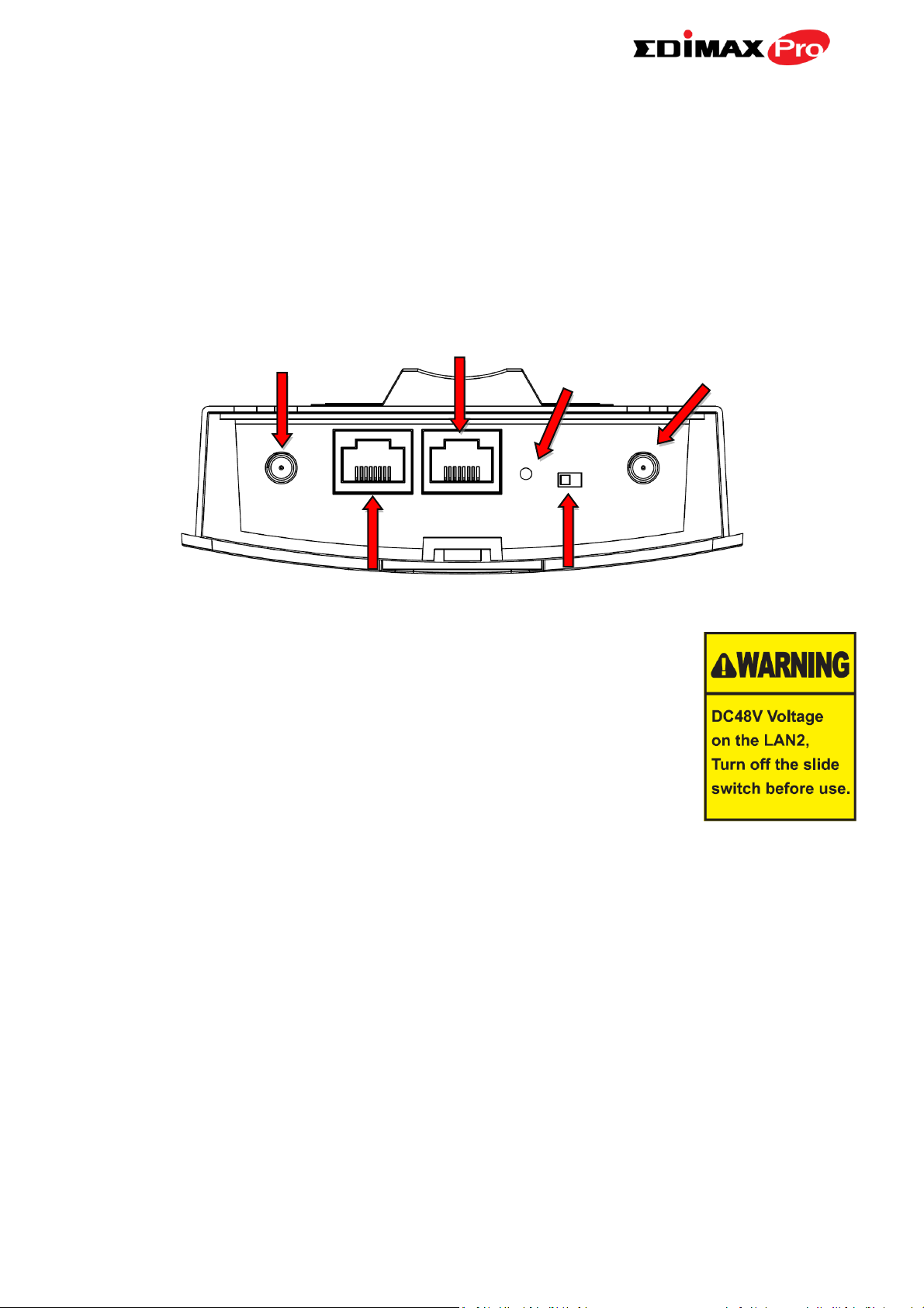
I-2. System Requirements
A LAN1 (PoE) IN
E PoE Out On/Off
D SMA
C Reset
- Existing cable/DSL modem & router
- Computer with web browser for access point configuration
I-3. Hardware Overview
A. LAN1 port with Power over Ethernet (Passive PoE) IN.
B. LAN2 port with Power over Ethernet (Passive PoE) OUT.
C. Reset the access point to factory default settings
D. SMA connector for optional antenna.
E. Switch the LAN2 (Passive PoE) OUT on/off.
3
Page 7

I-4. LED Status
LED Behavior
Power
Blue
The access point is on.
Off
The access point is off.
LAN 1 & 2
Blue
LAN port is connected.
Flashing
Activity (transferring and receiving)
Off
LAN port is unconnected.
Wireless
(Client mode
only)
Blue
Wireless enabled.
Flashing
Excellent/Good/Medium/Bad for RSSI Signal
Strength.
Off
Wireless disabled.
I-5. Reset
If you experience problems with your access point, you can reset the device
back to its factory settings. This resets all settings back to default.
1. Press and hold the reset button on the access point for at least 10
seconds. Then release the button.
You may need to use a pencil or similar sharp object to push the
reset button.
2. Wait for the access point to restart. The access point is ready for setup
when the LED is blue.
4
Page 8
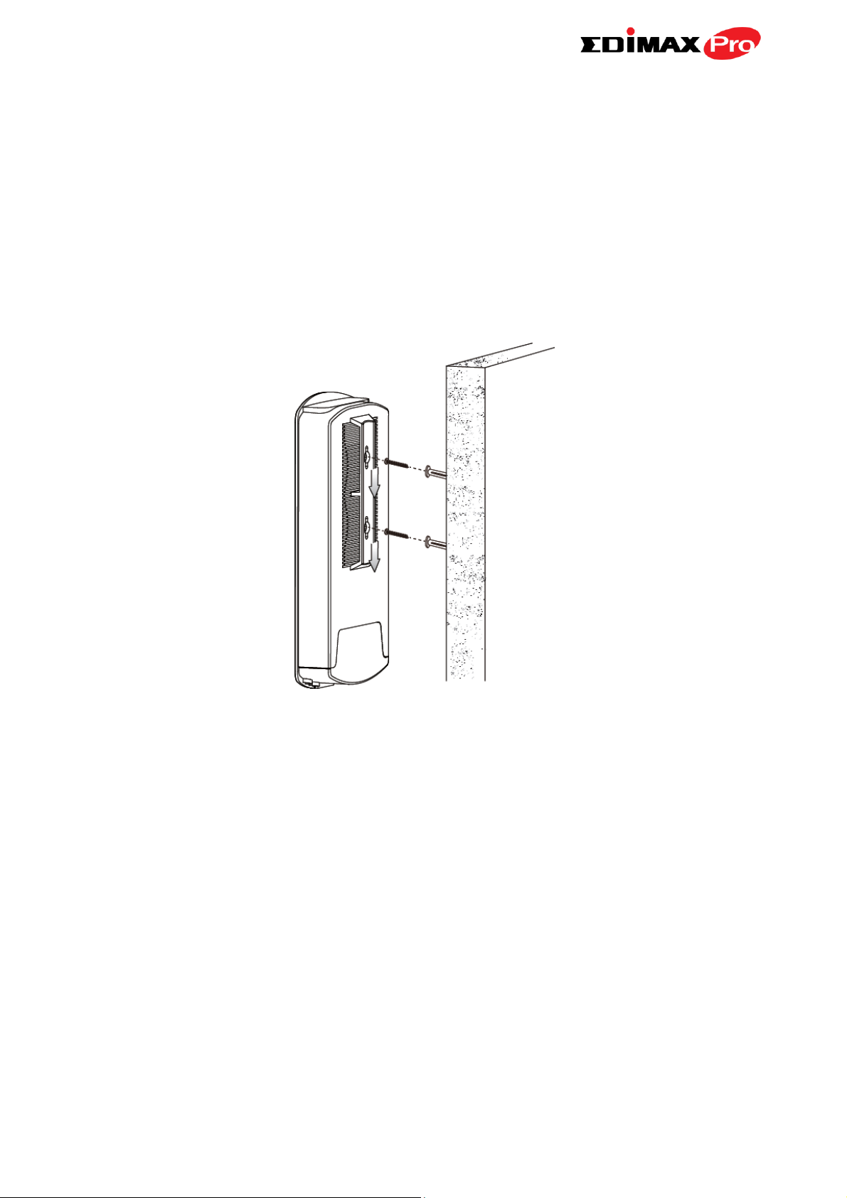
I-6. Mounting
The access point includes a mount for wall or pole which requires some
assembly.
Wall Mount
1. Attach the mount and access point to a wall using the included screws and
plugs.
5
Page 9

Pole Mount
2. Fix the mount and access point to a pole using the included pole mount
straps.
6
Page 10

I-7. Safety Information
In order to ensure the safe operation of the device and its users, please read
and act in accordance with the following safety instructions.
1. Do not place the access point in or near hot/humid places, such as a
kitchen or bathroom.
2. Do not pull any connected cable with force; carefully disconnect it from
the access point.
3. Handle the access point with care. Accidental damage will void the
warranty of the access point.
4. The device contains small parts which are a danger to small children
under 3 years old. Please keep the access point out of reach of children.
5. Do not place the access point on paper, cloth, or other flammable
materials. The access point may become hot during use.
6. There are no user-serviceable parts inside the access point. If you
experience problems with the access point, please contact your dealer
of purchase and ask for help.
7. If you smell burning or see smoke coming from the access point or
power adapter, then disconnect the access point and power adapter
immediately, as far as it is safely possible to do so. Call your dealer of
purchase for help.
7
Page 11

II. Quick Setup
The OAP900 Long Range 802.11ac Outdoor Access Point features a range of
powerful functions:
- 802.11ac high-speed wireless technology
- 16 SSIDs for management
- SNMP v1/v2c/v3
Your access point can be up and running in just a few minutes. It can function
as a standalone access point (AP mode), as part of an AP array (Managed AP
mode), or as a client bridge for WISP last-mile services (Client Bridge mode).
For use as a Managed AP in an AP array, the access point will automatically
switch mode when an AP Controller is configured as described in II-3.
Managed AP Mode: Edimax Pro NMS.
II-1. Passive PoE Injector
Do not connect a non-PoE device to the access point’s LAN2 (PoE
Out) port. The LAN2 port outputs 48 V and can damage a non PoE
device.
1. Connect the access point’s LAN1 (PoE In) port to the PoE injector’s PoE
port via Ethernet cable.
8
Page 12

2. Use an Ethernet cable to connect the access point’s LAN port to your
network: router, access point or switch. If it’s more convenient for initial
setup, you can connect a computer directly to the access point’s LAN port
instead.
3. Connect the PoE injector to a power source using the included power
adapter. Wait a moment for the access point to start up. The access point
is ready when the LED is blue.
9
Page 13
II-2. AP Mode
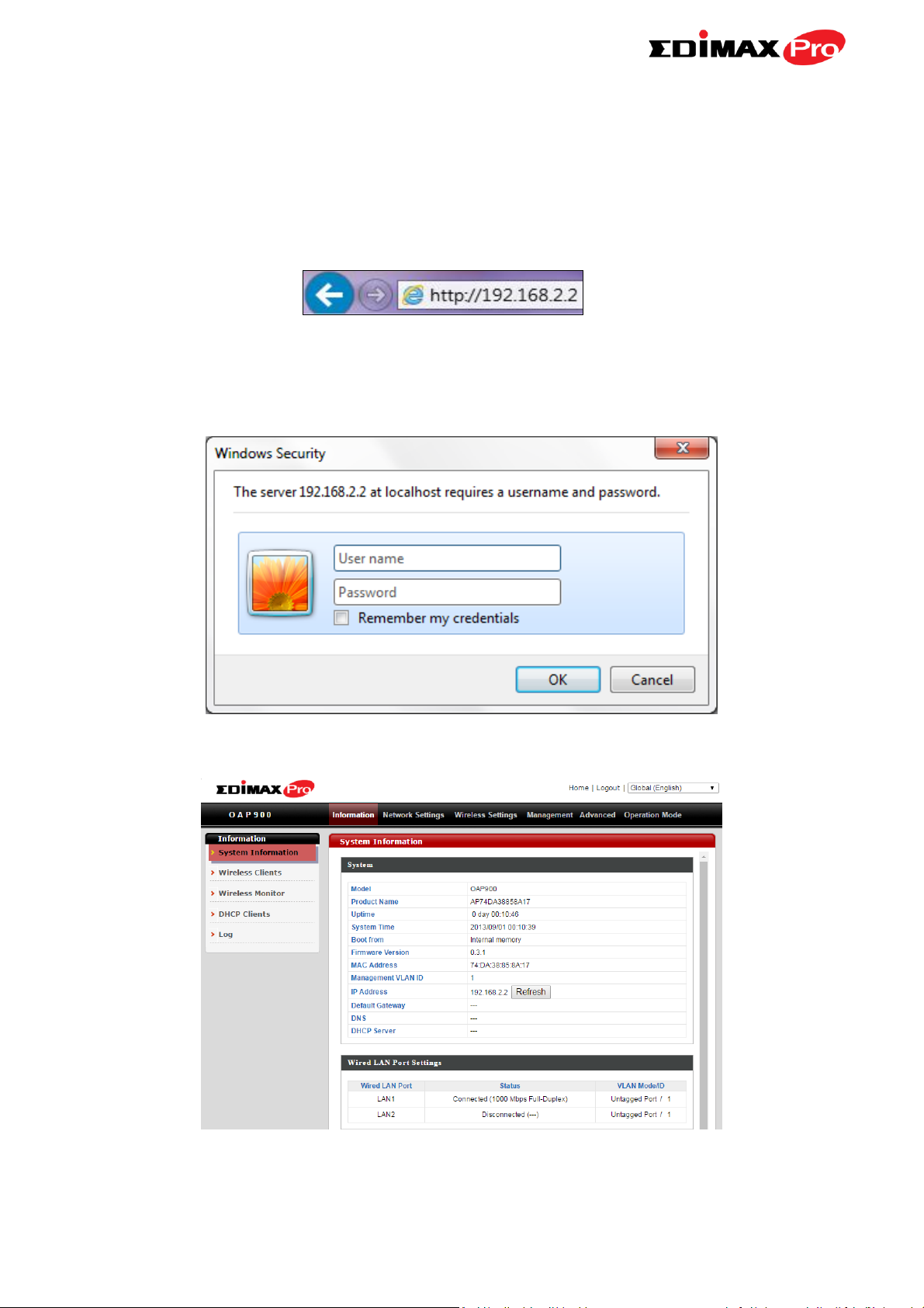
1. Enter the access point’s IP address into the URL bar of a web browser. The
default IP is 192.168.2.2. If the AP is connected to a DHCP server, ensure
you use the correct address.
2. You will be prompted for a user name and password. Enter the default
username “admin” and the default password “1234”.
3. You will arrive at the “System Information” screen shown below.
The next steps will help you to configure the following basic settings of the
access point:
10
Page 14
- LAN IP Address
- 5GHz SSID & Security
- Administrator Name & Password
- Time & Date
It is recommended you configure these settings before using the
access point.
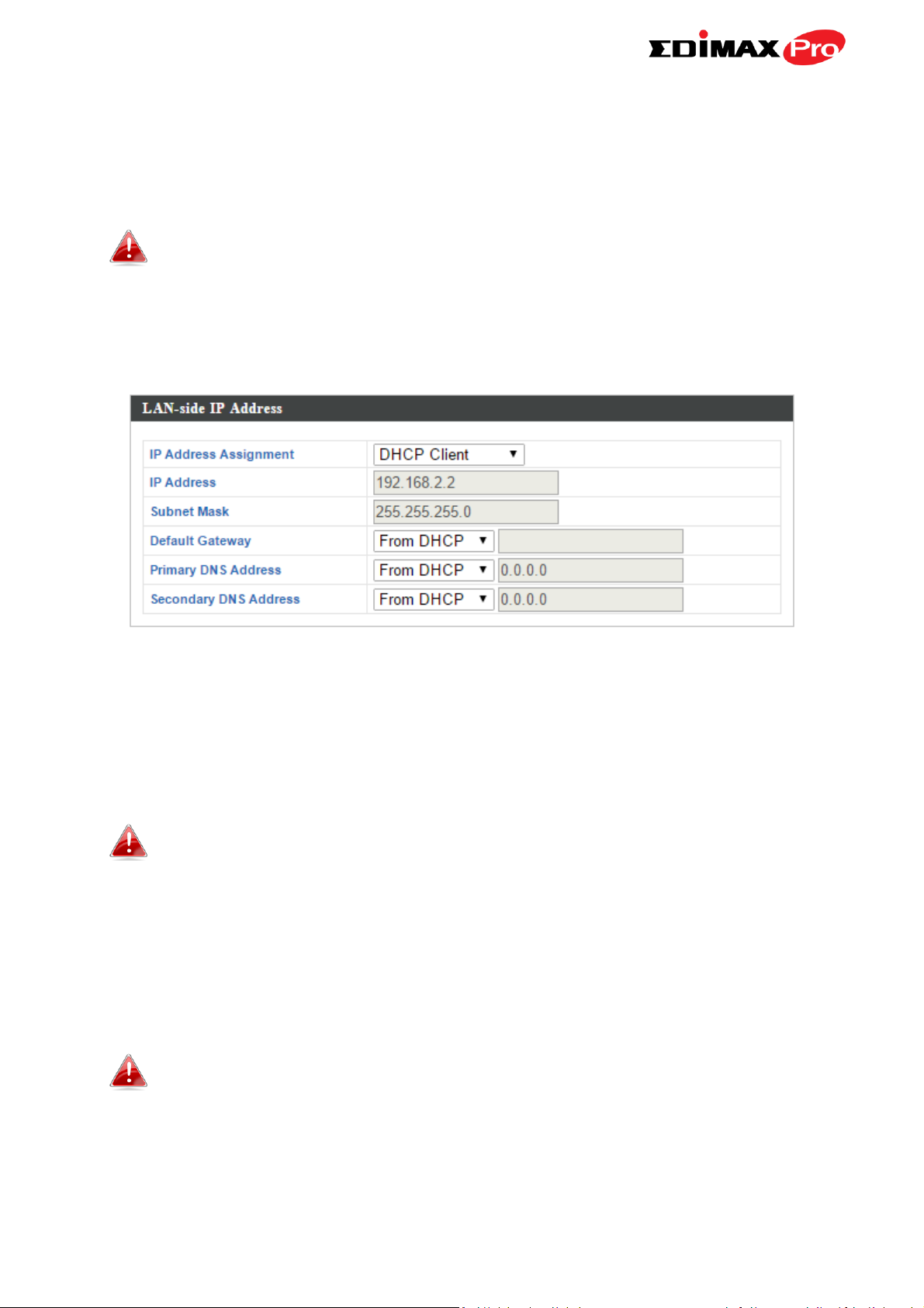
1. To change the access point’s LAN IP address, go to “Network Settings” >
“LAN-side IP Address” and you will see the screen below.
2. Enter the IP address settings you wish to use for your access point. You
can use a dynamic (DHCP) or static IP address, depending on your network
environment. Click “Apply” to save the changes and wait a few moments
for the access point to reload.
When you change your access point’s IP address, you need to use
the new IP address to access the browser based configuration
interface instead of the default IP 192.168.2.2.
3. To change the SSID of your access point’s 5GHz wireless network(s), go to
“Wireless Settings” > “5GHz 11ac” > “Basic”. Enter the new SSID for your
2.4GHz wireless network in the “SSID1” field and click “Apply”.
To utilize multiple 5GHz SSIDs, open the drop down menu labelled
“Enable SSID number” and select how many SSIDs you require.
Then enter a new SSID in the corresponding numbered fields
below, before clicking “Apply”.
11
Page 15
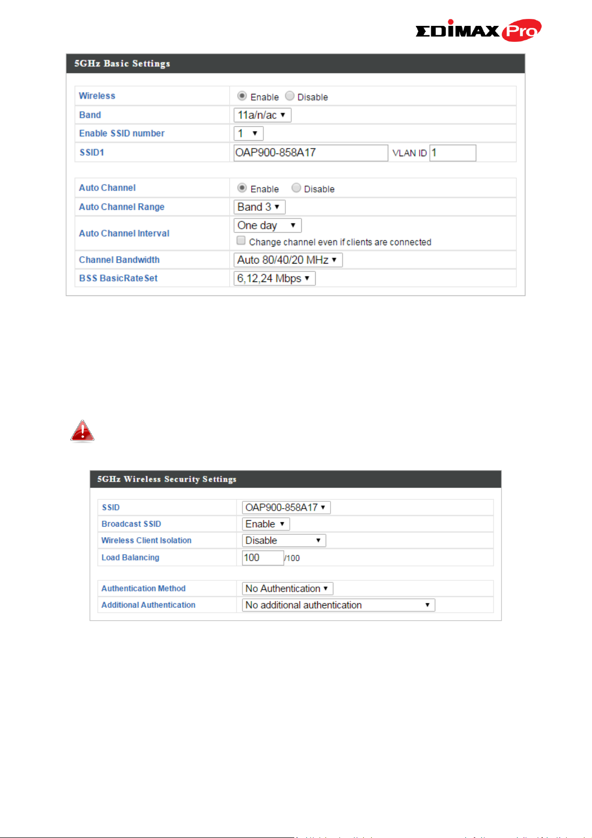
4. To configure the security of your access point’s 5GHz wireless network(s),
go to “Wireless Settings” > “5GHz 11ac 11an” > “Security”. Select an
“Authentication Method” and enter a “Pre-shared Key” or “Encryption Key”
depending on your choice, then click “Apply”.
If using multiple SSIDs, specify which SSID to configure using the
“SSID” drop down menu.
5. To change the administrator name and password for the browser based
configuration interface, go to “Management” > “Admin”.
12
Page 16
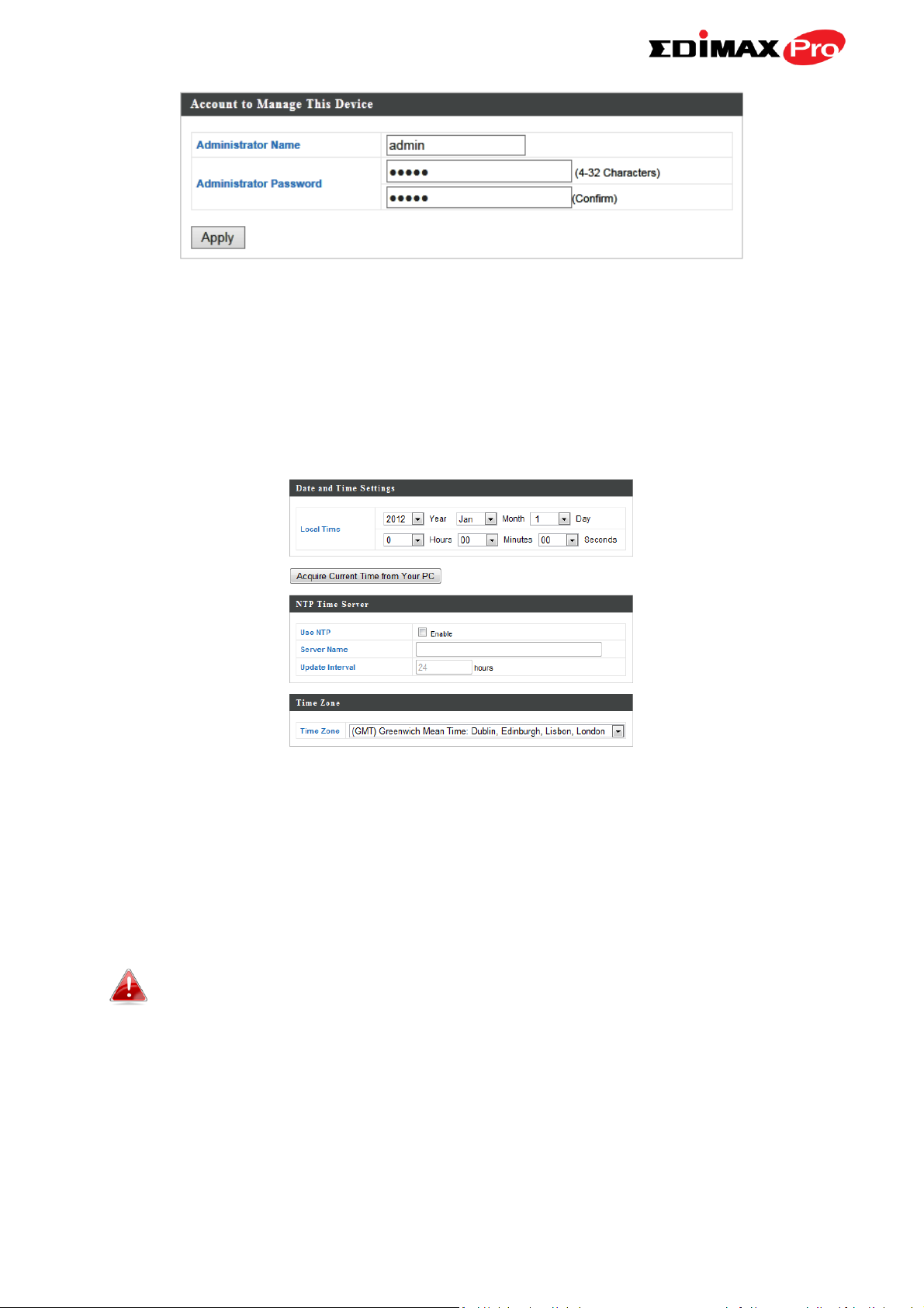
6. Complete the “Administrator Name” and “Administrator Password” fields
and click “Apply”.
7. To set the correct time for your access point, go to “Management” >
“Date and Time Settings”.
8. Set the correct time and time zone for your access point using the drop
down menus. The access point also supports NTP (Network Time Protocol)
so alternatively you can enter the host name or IP address of a time server.
Click “Apply” when you are finished.
You can use the “Acquire Current Time from your PC” button if
you wish to set the access point to the same time as your PC.
9. The basic settings of your access point are now configured.
13
Page 17
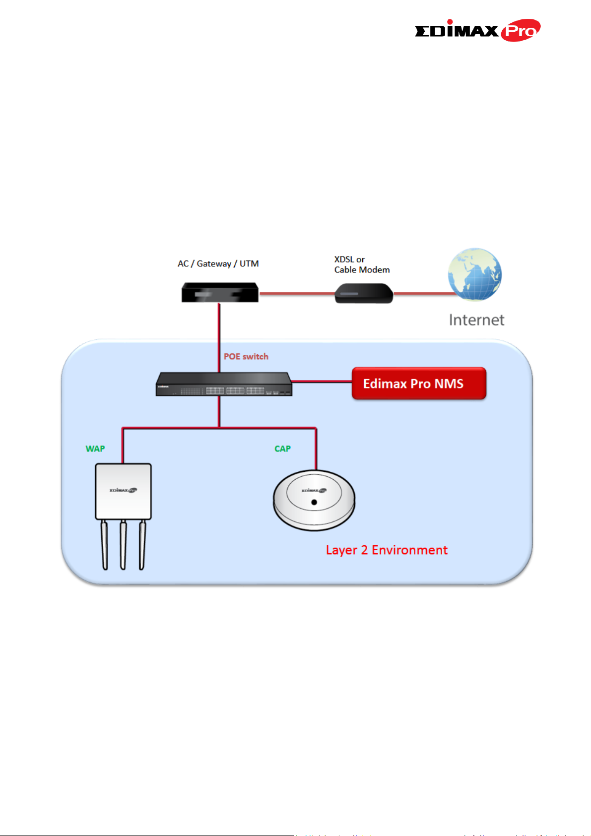
II-3. Managed AP Mode: Edimax Pro NMS
Edimax Pro Network Management Suite (NMS) supports the central
management of a group of access points, otherwise known as an AP Array.
NMS supports up to 16 Edimax Pro access points with no additional wireless
controller required or 128 access points with the APC 500 AP controller reducing costs and facilitating efficient remote AP management.
Edimax Pro NMS is simple to setup. An overview of the system is shown
below:
One AP (access point) is designated as the AP Controller (master) and other
connected Edimax Pro APs are automatically designated as Managed APs
(slaves). Using Edimax Pro NMS you can monitor, configure and manage all
Managed APs (up to 128) from the single AP Controller.
The OAP900 functions as a Managed AP and cannot act as an AP
Controller.
14
Page 18
When using an Edimax NMS AP controller, other connected APs are
automatically set to Managed APs. In the case that the AP Controller
cannot find your OAP900 as a Managed AP, you can configure the
setting manually as below:
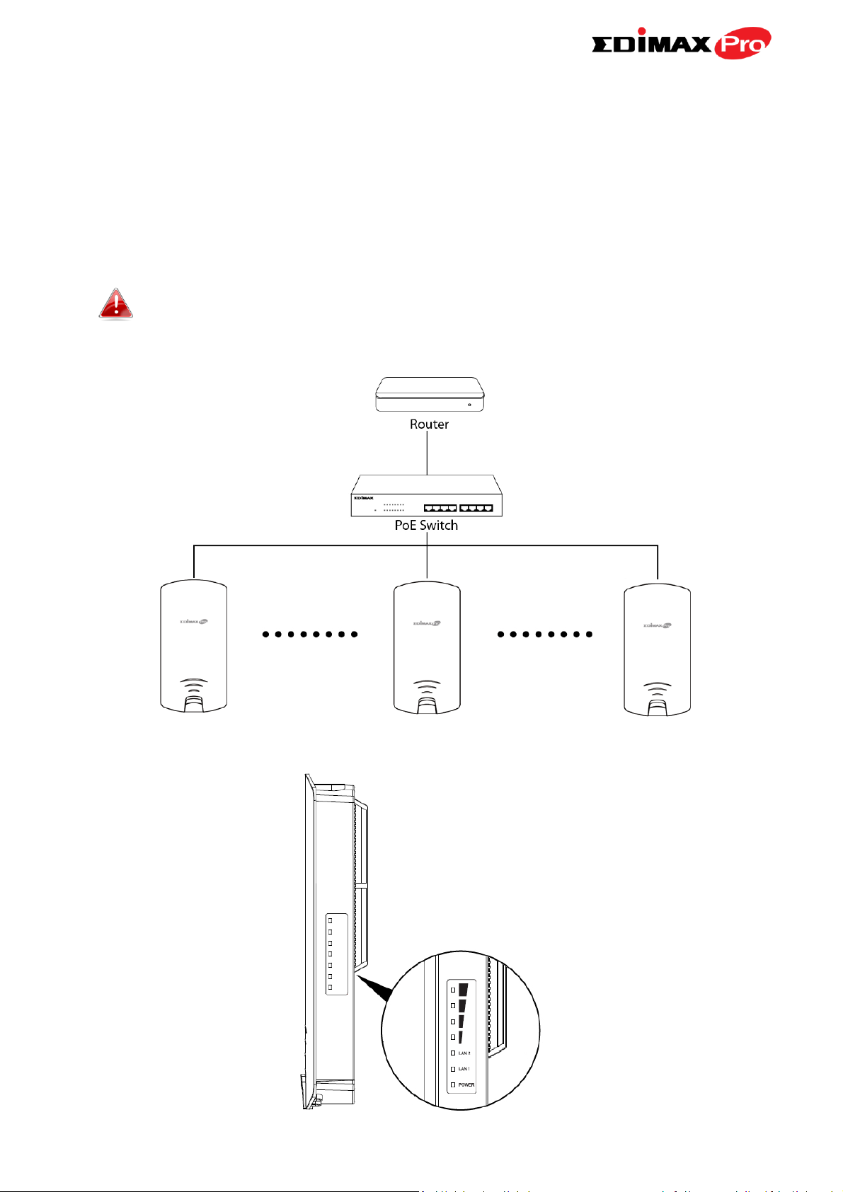
1. Ensure all APs including your OAP900 are connected to an Ethernet or PoE
switch which is connected to a gateway/router.
You can use your router as a DHCP server or you can later
configure your AP Controller as a DHCP server.
2. Ensure all APs are powered on and check LEDs.
15
Page 19
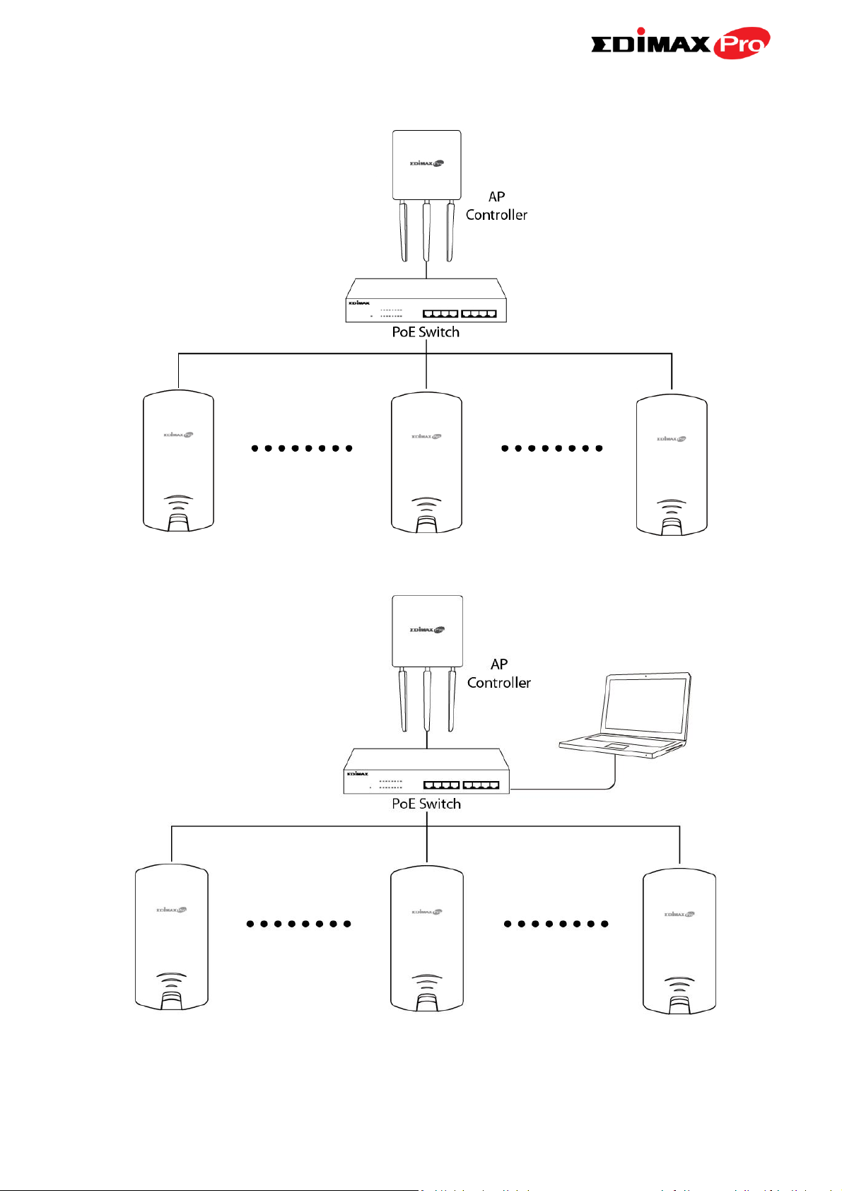
3. Ensure you have setup and designated one AP as the AP Controller which
will manage all other connected APs (up to 128 depending on model).
4. Connect a computer to the OAP900 via PoE switch using an Ethernet cable.
5. Open a web browser and enter the OAP900’s IP address in the address
field. The default IP address is 192.168.2.2
16
Page 20
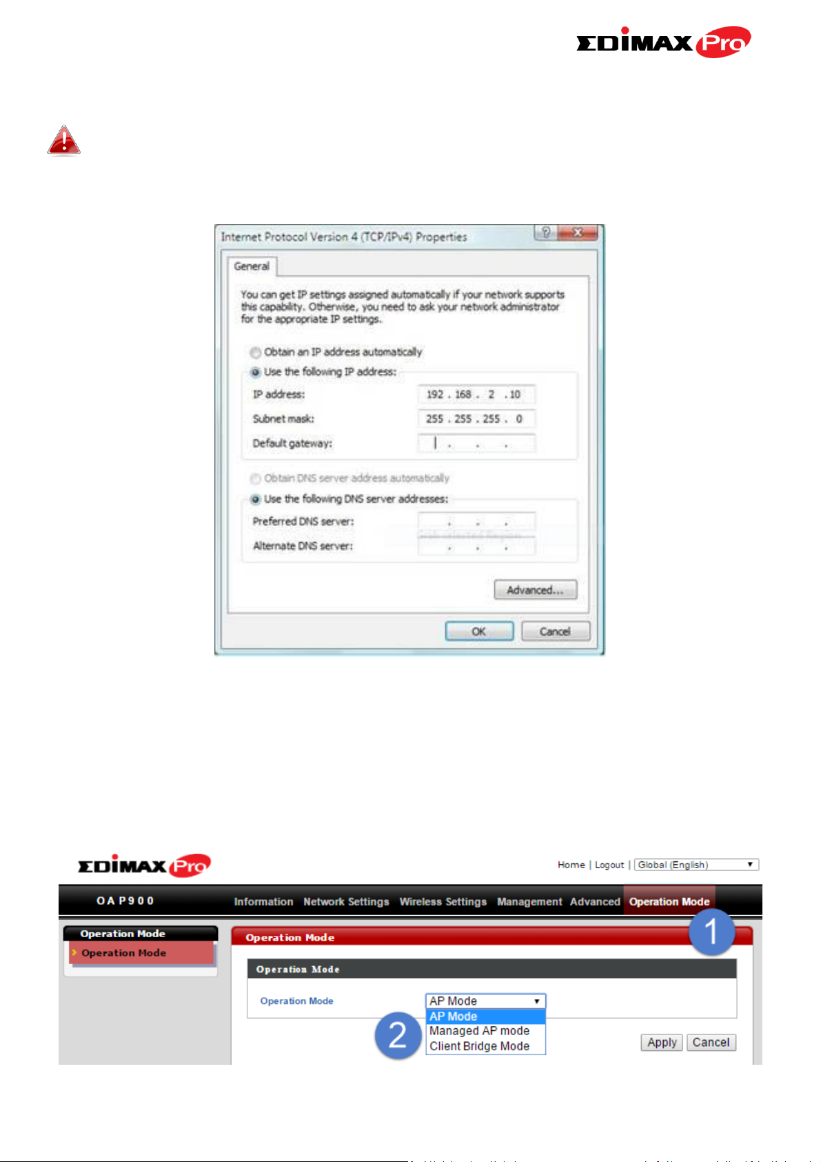
Your computer’s IP address must be in the same subnet as the AP
Controller. If you changed the AP Controller’s IP address, or if your
gateway/router uses a DHCP server, ensure you enter the correct IP
address.
6. Enter the username & password to login. The default username &
password are admin & 1234.
7. You will arrive at the Edimax Pro NMS Dashboard. Go to “Operation
Mode” and select “Managed AP Mode” from the drop down menu.
17
Page 21
8. Click “Apply” to save the settings and your AP Controller & Managed APs
should be fully functional. Use Edimax NMS on your AP controller to
manage & monitor your Managed APs.
Refer to your AP controller’s user manual for help with Edimax
NMS.
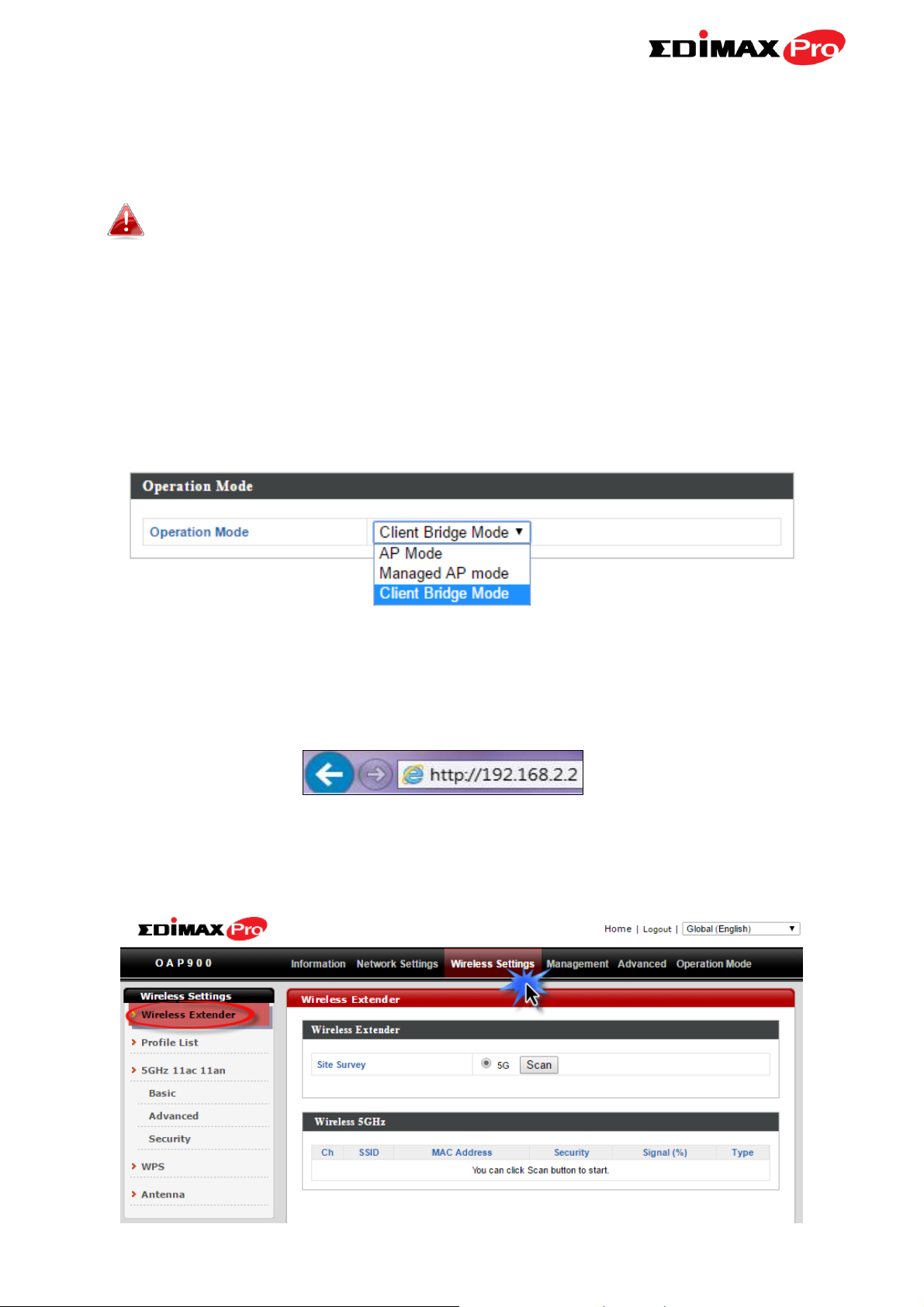
II-4. Client Bridge Mode
Client Bridge mode enables the OAP900 to wirelessly connect to an AP’s SSID
while remaining in the same IP address range as that AP – the WAN and LAN
are on the same subnet. This is ideal for last-mile solutions. Settings here are
saved as profiles.
1. Enter the access point’s IP address into the URL bar of a web browser. The
default IP is 192.168.2.2. If the AP is connected to a DHCP server, ensure
you use the correct address.
2. Enter the default username “admin” and the default password “1234”,
and then go to Wireless Settings Wireless Extender.
18
Page 22
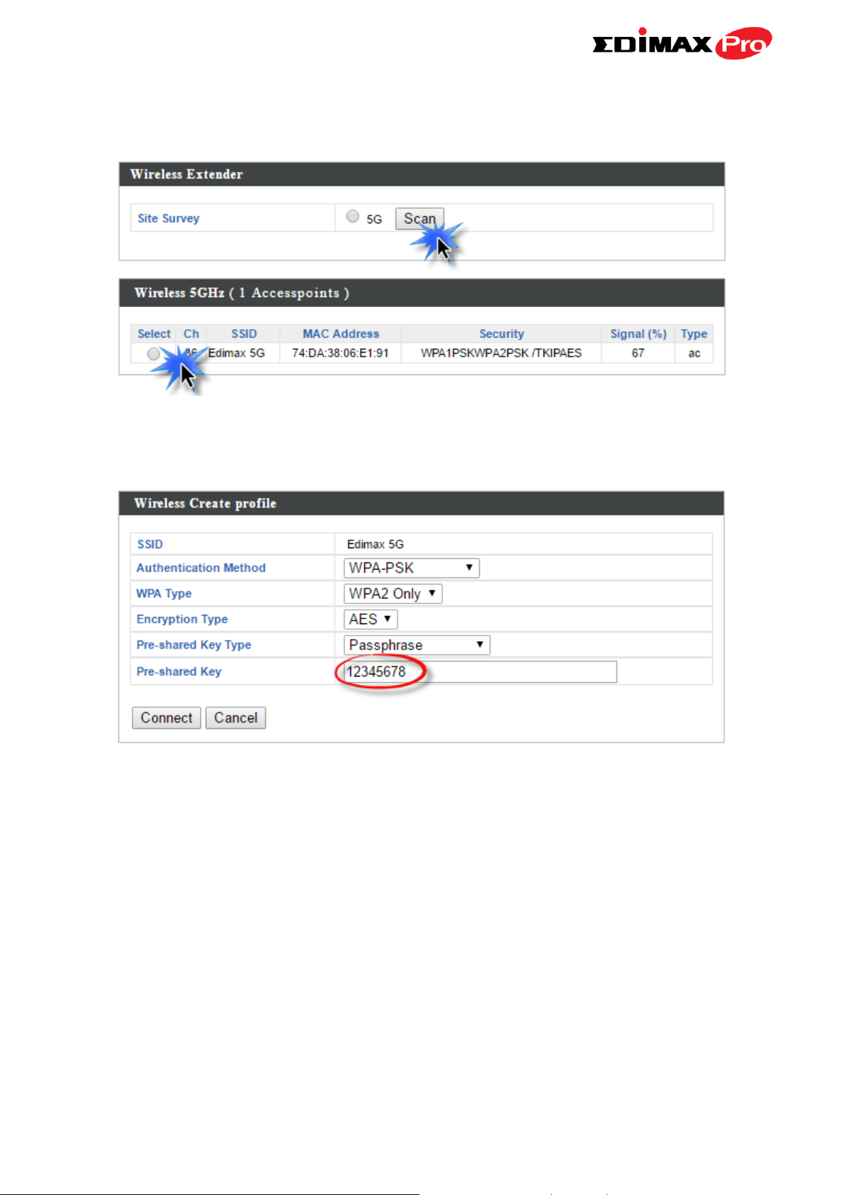
3. Click Scan to search for and display available SSIDs and click Select to
connect to an available source SSID.
4. Enter the encryption information for the SSID and then click Connect.
19
Page 23

IV. Browser Based Configuration Interface
In Managed AP mode some functions of the browser based
configuration interface are disabled. Please use Edimax Pro NMS
on your Controller AP to configure your Managed AP(s).
The browser-based configuration interface enables you to configure the
access point’s advanced features. The OAP900 features a range of advanced
functions such as MAC filtering, MAC RADIUS authentication, VLAN
configurations, up to 16 SSIDs and many more. To access the browser based
configuration interface:
1. Connect a computer to your access point using an Ethernet cable.
2. Enter the access point’s IP address into the URL bar of a web browser. The
default IP is 192.168.2.2. If the AP is connected to a DHCP server, ensure
you use the correct address.
3. You will be prompted for a username and password. The default
username is “admin” and the default password is “1234”, though it was
recommended that you change the password during setup.
If you cannot remember your password, reset the access point
back to its factory default settings. Refer to I-5. Reset
4. You will arrive at the “System Information” screen shown below.
20
Page 24
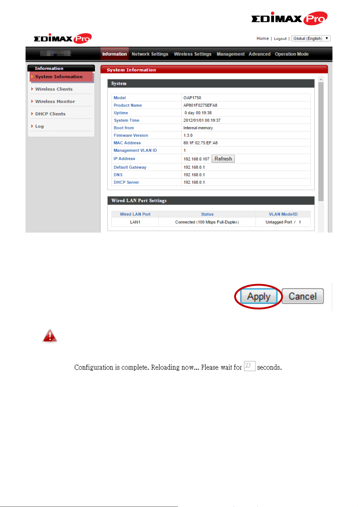
5.Use the menu across the top and down the left side to navigate. Click
“Apply” to save changes and reload the access point, or “Cancel” to cancel
changes.
Please wait a few seconds for the access point to reload after you
“Apply” changes, as shown below.
6. Please refer to the following chapters for full descriptions of the browser
based configuration interface features.
21
Page 25
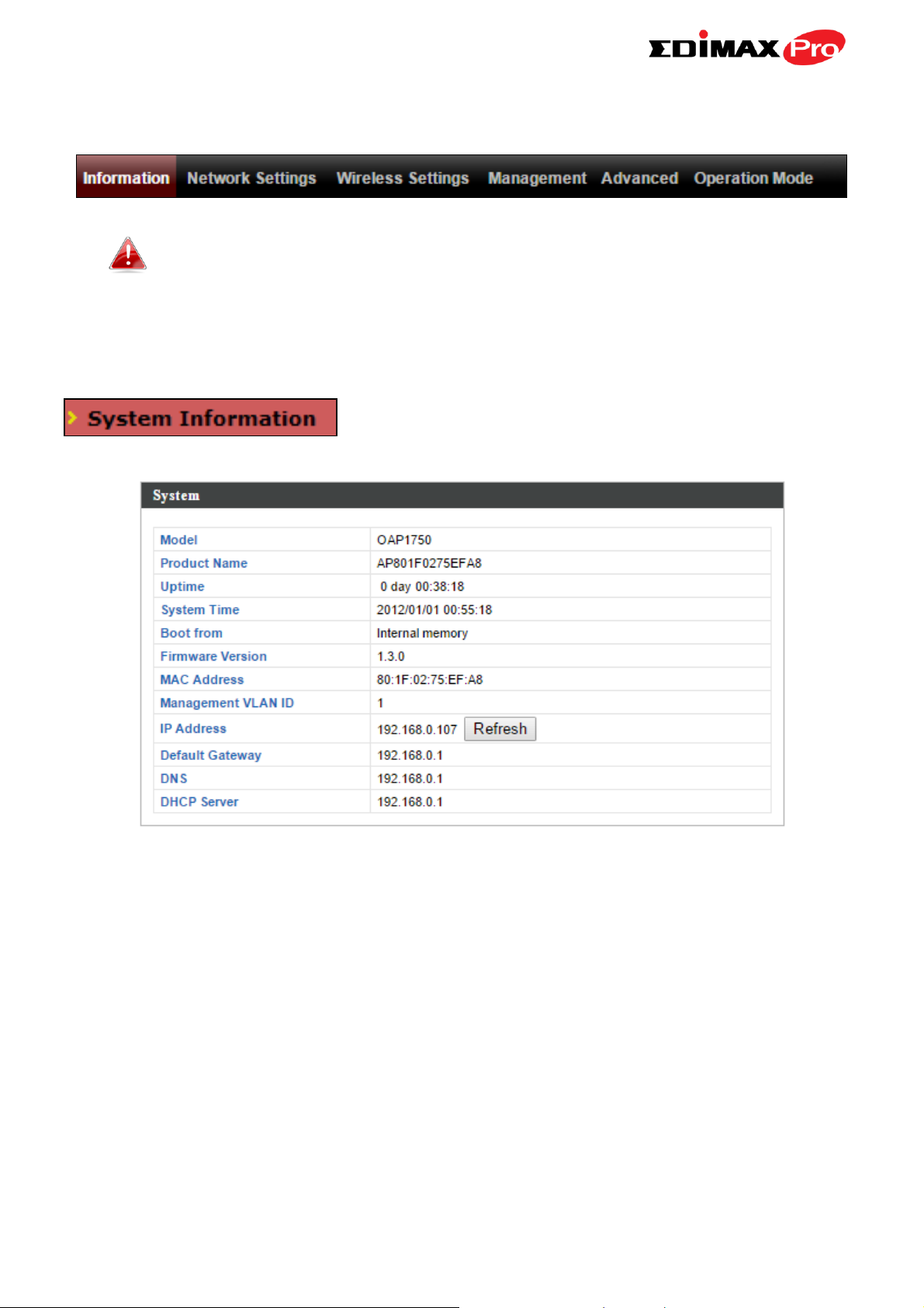
IV-1. Information
Screenshots displayed are examples. The information shown on
your screen will vary depending on your configuration.
IV-1-1. System Information
The “System Information” page displays basic
system information about the access point.
22
Page 26
System
Model
Displays the model number of the access
point.
Product Name
Displays the product name for reference,
which consists of “AP” plus the MAC address.
Uptime
Displays the total time since the device was
turned on.
Boot From
Displays information for the booted
hardware, booted from either USB or internal
memory.
Firmware Version
Displays the firmware version.
MAC Address
Displays the access point’s MAC address.
Management VLAN
ID
Displays the management VLAN ID.
IP Address
Displays the IP address of this device. Click
“Refresh” to update this value.
Default
Displays the IP address of the default
23
Page 27

Gateway
gateway.
DNS
IP address of DNS (Domain Name Server)
DHCP Server
IP address of DHCP Server.
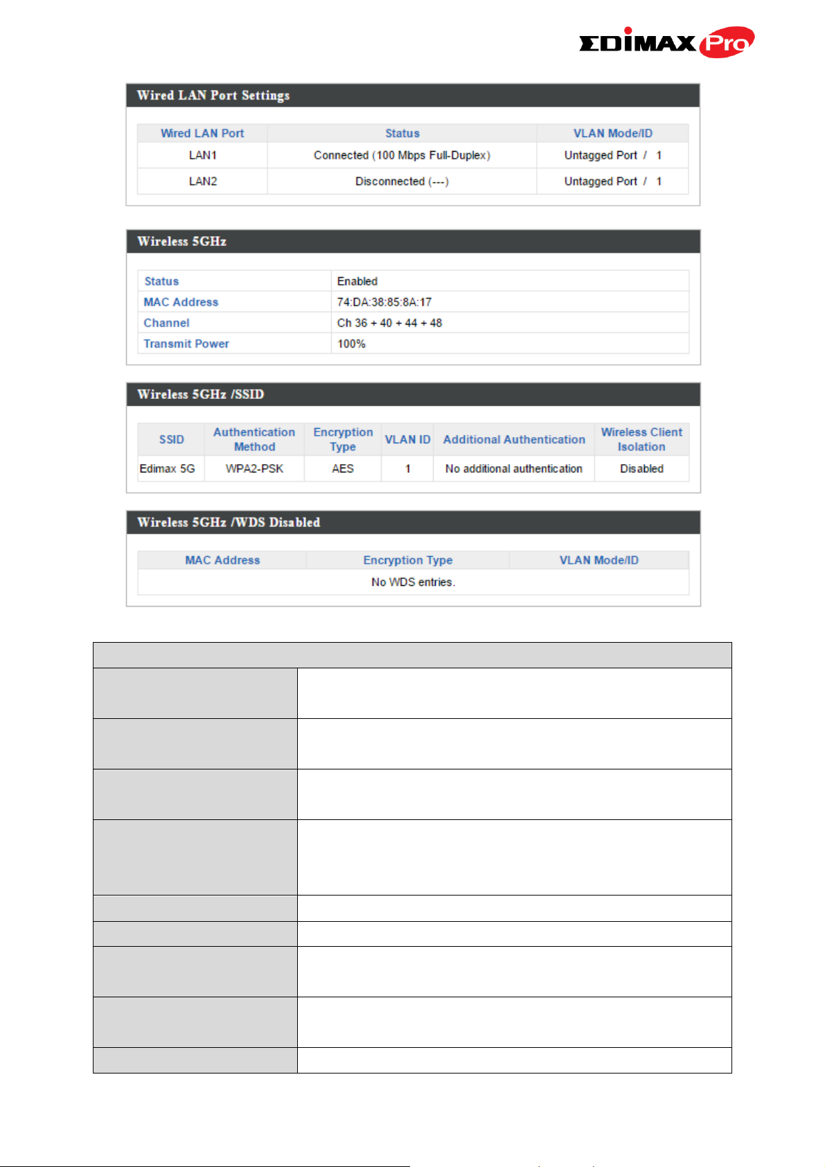
Wired LAN Port Settings
Wired LAN Port
Specifies which LAN port.
Status
Displays the status of the specified LAN port
(connected or disconnected).
VLAN Mode/ID
Displays the VLAN mode (tagged or untagged)
and VLAN ID for the specified LAN port. See
IV-2-3. VLAN
Wireless 5GHz
Status
Displays the status of the 2.4GHz or 5GHz
wireless (enabled or disabled).
MAC Address
Displays the access point’s MAC address.
Channel
Displays the channel number the specified
wireless frequency is using for broadcast.
Transmit Power
Displays the wireless radio transmit power
level as a percentage.
Wireless 5GHz / SSID
SSID
Displays the SSID name(s) for the specified
frequency.
Authentication
Method
Displays the authentication method for the
specified SSID. See IV-3. Wireless Settings
Encryption Type
Displays the encryption type for the specified
SSID. See IV-3. Wireless Settings
VLAN ID
Displays the VLAN ID for the specified SSID.
See IV-2-3. VLAN
Additional
Authentication
Displays the additional authentication type for
the specified SSID. See IV-3. Wireless Settings
Wireless Client
Isolation
Displays whether wireless client isolation is in
use for the specified SSID. See IV-2-3. VLAN
Wireless 5GHz / WDS Status
MAC Address
Displays the peer access point’s MAC address.
Encryption Type
Displays the encryption type for the specified
WDS. See IV-3-1-4. WDS
24
Page 28
VLAN Mode/ID
Displays the VLAN ID for the specified WDS.
See IV-3-1-4. WDS
Refresh
Click to refresh all information.
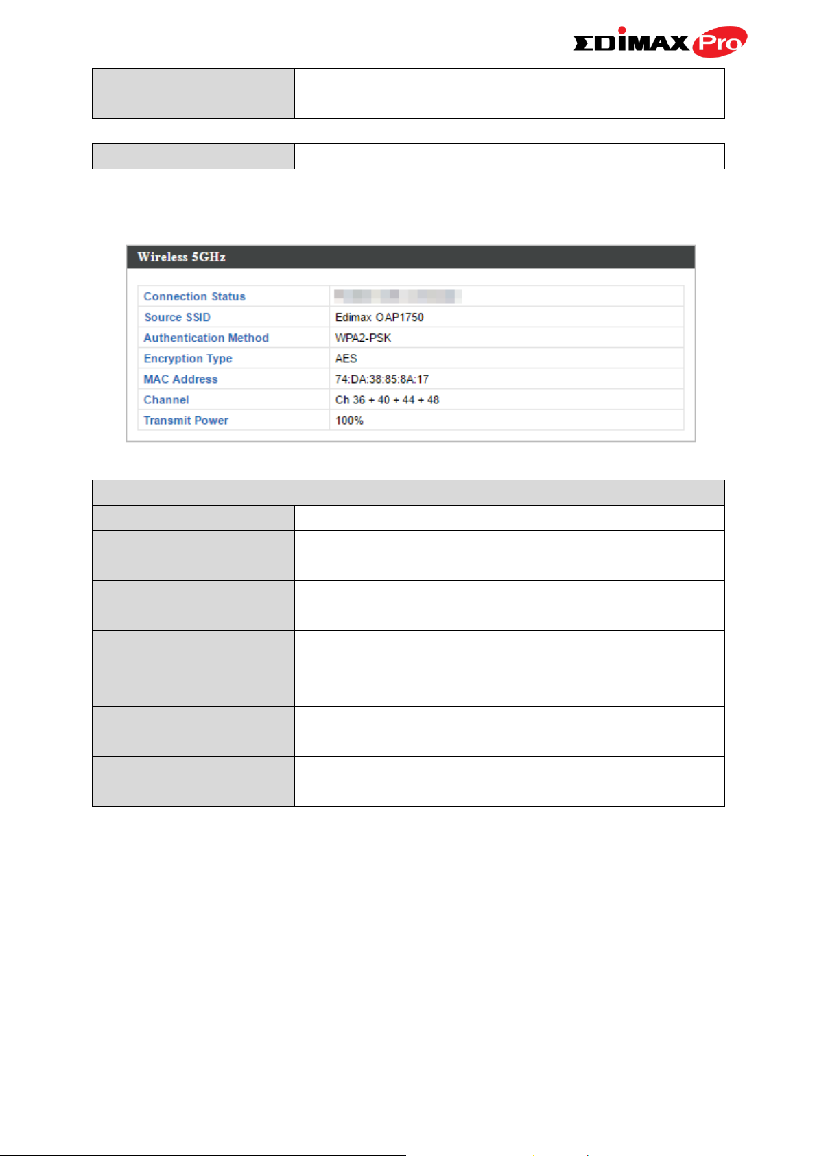
Wireless 2.4GHZ (5GHz) / SSID
Connection Status
Current status of the repeater’s connection.
Source SSID
Displays the SSID name(s) for the repeater’s
source.
Authentication
Method
Displays the authentication method for the
specified SSID. See IV-3. Wireless Settings
Encryption Type
Displays the encryption type for the specified
SSID. See IV-3. Wireless Settings
MAC Address
Displays the access point’s MAC address.
Channel
Displays the channel number the specified
wireless frequency is using for broadcast.
Transmit Power
Displays the wireless radio transmit power
level as a percentage.
Client Bridge Mode:
25
Page 29
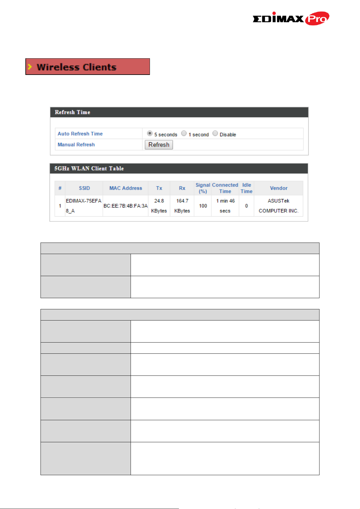
IV-1-2. Wireless Clients
Refresh time
Auto Refresh Time
Select a time interval for the client table list to
automatically refresh.
Manual Refresh
Click refresh to manually refresh the client
table.
5GHz WLAN Client Table
SSID
Displays the SSID which the client is
connected to.
MAC Address
Displays the MAC address of the client.
Tx
Displays the total data packets transmitted by
the specified client.
Rx
Displays the total data packets received by
the specified client.
Signal (%)
Displays the wireless signal strength for the
specified client.
Connected Time
Displays the total time the wireless client has
been connected to the access point.
Idle Time
Client idle time is the time for which the client
has not transmitted any data packets i.e. is
idle.
The “Wireless Clients” page displays
information about all wireless clients
connected to the access point on the 2.4GHz or 5GHz frequency.
26
Page 30

Vendor
The vendor of the client’s wireless adapter is
displayed here.
27
Page 31

IV-1-3. Wireless Monitor
Wireless Monitor
Site Survey
Select which frequency (or both) to scan, and
click “Scan” to begin.
Channel Survey
Result
After a scan is complete, click “Export” to save
the results to local storage.
Site Survey Results
Ch
Displays the channel number used by the
specified SSID.
SSID
Displays the SSID identified by the scan.
MAC Address
Displays the MAC address of the wireless
router/access point for the specified SSID.
Security
Displays the authentication/encryption type
of the specified SSID.
Signal (%)
Displays the current signal strength of the
SSID.
Type
Displays the 802.11 wireless networking
standard(s) of the specified SSID.
Vendor
Displays the vendor of the wireless
router/access point for the specified SSID.
Wireless Monitor is a tool built into the access
point to scan and monitor the surrounding
wireless environment. Select a frequency and click “Scan” to display a list of
all SSIDs within range along with relevant details for each SSID.
28
Page 32

IV-1-4. DHCP Client Table
DHCP Client Table
IP Address
Displays the IP address of listed DHCP client.
MAC Address
Displays the MAC address of listed DHCP
client.
Expiration Time
Displays the expiration time for listed DHCP
client.
enabled.
The DHCP client table displays information
about DHCP clients when DHCP server is
29
Page 33

IV-1-5. Log
Save
Click to save the log as a file on your local
computer.
Clear
Clear all log entries.
Refresh
Refresh the current log.
The system log displays system operation
information such as up time and connection
processes. This information is useful for network administrators.
When the log is full, old entries are overwritten. Use the Search
function to quickly locate log entries.
30
Page 34

The following information/events are recorded by the log:
USB
Mount & unmount
Wireless Client
Connected & disconnected
Key exchange success & fail
Authentication
Authentication fail or successful.
Association
Success or fail
WPS
M1 - M8 messages
WPS success
Change Settings
System Boot
Displays current model name
NTP Client
Wired Link
LAN Port link status and speed status
Proxy ARP
Proxy ARP module start & stop
Bridge
Bridge start & stop.
SNMP
SNMP server start & stop.
HTTP
HTTP start & stop.
HTTPS
HTTPS start & stop.
SSH
SSH-client server start & stop.
Telnet
Telnet-client server start or stop.
WLAN (5G)
WLAN (5G) channel status and country/region status
31
Page 35

IV-2. Network Settings
LAN-side IP Address
IP Address
Assignment
Select “DHCP Client” for your access point to
be assigned a dynamic IP address from your
router’s DHCP server, or select “Static IP” to
manually specify a static/fixed IP address for
your access point (below).
IP Address
Specify the IP address here. This IP address
will be assigned to your access point and will
replace the default IP address.
Subnet Mask
Specify a subnet mask. The default value is
255.255.255.0
Screenshots displayed are examples. The information shown on
your screen will vary depending on your configuration.
IV-2-1. LAN-Side IP Address
The “LAN-side IP address” page allows you to
configure your access point on your Local Area
Network (LAN). You can enable the access point to dynamically receive an IP
address from your router’s DHCP server or you can specify a static IP address
for your access point, as well as configure DNS servers.
The access point’s default IP address is 192.168.2.2.
32
Page 36

Default Gateway
For DHCP users, select “From DHCP” to get
default gateway from your DHCP server or
“User-Defined” to enter a gateway manually.
For static IP users, the default value is blank.
Primary Address
DHCP users can select “From DHCP” to get
primary DNS server’s IP address from DHCP or
“User-Defined” to manually enter a value. For
static IP users, the default value is blank.
Secondary Address
Users can manually enter a value when DNS
server’s primary address is set to
“User-Defined”.
DHCP users can select to get DNS servers’ IP address from DHCP or manually
enter a value. For static IP users, the default value is blank.
33
Page 37

IV-2-2. LAN Port
Wired LAN Port
Identifies LAN port number.
Enable
Enable/disable specified LAN port.
Speed & Duplex
Select a speed & duplex type for specified LAN
port, or use the “Auto” value. LAN ports can
operate up to 1000Mbps and full-duplex
enables simultaneous data packets
transfer/receive.
Flow Control
Enable/disable flow control. Flow control can
pause new session request until current data
processing is complete, in order to avoid
device overloads under heavy traffic.
802.3az
Enable/disable 802.3az. 802.3az is an Energy
Efficient Ethernet feature which disables
unused interfaces to reduce power usage.
The “LAN Port” page allows you to
configure the settings for your access
point’s two wired LAN (Ethernet) ports.
34
Page 38

IV-2-3. VLAN
VLAN Interface
Wired LAN
Port/Wireless
Identifies LAN port number and wireless SSIDs.
VLAN Mode
Select “Tagged Port” or “Untagged Port” for
specified LAN interface.
VLAN ID
Set a VLAN ID for specified interface, if
“Untagged Port” is selected.
Management VLAN
VLAN ID
Specify the VLAN ID of the management VLAN.
Only the hosts belonging to the same VLAN can
manage the device.
The “VLAN” (Virtual Local Area Network)
enables you to configure VLAN settings. A
VLAN is a local area network which maps
workstations virtually instead of physically and allows you to group together
or isolate users from each other. VLAN IDs 1 – 4095 are supported.
VLAN IDs in the range 1 – 4095 are supported.
35
Page 39

IV-3. Wireless Settings
Screenshots displayed are examples. The information shown on
your screen will vary depending on your configuration.
IV-3-1. Wireless Extender
Only available in Client Bridge Mode
The wireless extender page displays details
about the APs wireless connection in client
bridge mode and enables you to connect to a source SSID. Settings are saved
as profiles. Click Scan to search for and display available SSIDs and click Select
to connect to an available SSID.
36
Page 40

Wireless 5GHz
Select
Click to select an SSID and display a new Create
Profile window to enter security information
(below).
Channel
Displays the channel number of listed SSID.
SSID
Displays the SSID.
MAC Address
Displays the MAC address of specified SSID.
Security
Displays the existing security type for listed
SSID.
Signal (%)
Displays the available signal strength for listed
SSID.
Type
Displays the wireless 802.11 standard for each
SSID.
Wireless Create Profile
SSID
Displays the selected source SSID for this
profile.
Authentication
Method
Select the source SSIDs authentication method
and enter encryption key/pre-shared key.
37
Page 41

IV-3-2. Profile List
Wireless Create Profile
SSID
Displays the selected source SSID for this
profile.
Authentication
Method
Select the source SSIDs authentication method
and enter encryption key/pre-shared key.
Only available in Client Bridge Mode
Client bridge mode settings are saved as
profiles. Profiles can be edited and multiple
profiles can be created to switch between
profiles easily as required. Select an existing profile and click Edit or Connect.
38
Page 42

IV-3-3. 5GHz 11ac 11an
Wireless
Enable or disable the access point’s 5GHz
wireless radio. When disabled, no 5GHz SSIDs
will be active.
Band
Select the wireless standard used for the
The “5GHz 11ac 11an” menu allows you to view
and configure information for your access point’s
5GHz wireless network across five categories: Basic, Advanced, Security, WDS
& Schedule.
IV-3-3-1. Basic
The “Basic” screen displays basic settings for
your access point’s 5GHz Wi-Fi network (s).
39
Page 43

access point. Combinations of 802.11a,
802.11n & 802.11ac can be selected.
Enable SSID Number
Select how many SSIDs to enable for the 5GHz
frequency from the drop down menu. A
maximum of 16 can be enabled.
SSID#
Enter the SSID name for the specified SSID (up
to 16). The SSID can consist of any
combination of up to 32 alphanumeric
characters.
VLAN ID
Specify a VLAN ID for each SSID.
Auto Channel
Enable/disable auto channel selection. Auto
channel selection will automatically set the
wireless channel for the access point’s 5GHz
frequency based on availability and potential
interference. When disabled, select a channel
manually as shown in the next table.
Auto Channel Range
Select a range from which the auto channel
setting (above) will choose a channel.
Auto Channel
Interval
Specify a frequency for how often the auto
channel setting will check/reassign the
wireless channel. Check/uncheck the “Change
channel even if clients are connected” box
according to your preference.
Channel Bandwidth
Set the channel bandwidth: 20MHz (lower
performance but less interference), Auto
40/20MHz or Auto 80/40/20MHz
(automatically select based on interference
level).
BSS BasicRate Set
Set a Basic Service Set (BSS) rate: this is a
series of rates to control communication
frames for wireless clients.
Channel
Select a wireless channel.
Channel Bandwidth
Set the channel bandwidth: 20MHz (lower
performance but less interference), Auto
40/20MHz or Auto 80/40/20MHz
(automatically select based on interference
level).
When auto channel is disabled, select a wireless channel manually:
40
Page 44

BSS BasicRate Set
Set a Basic Service Set (BSS) rate: this is a
series of rates to control communication
frames for wireless clients.
Guard Interval
Set the guard interval. A shorter interval can
improve performance.
802.11n Protection
Enable/disable 802.11n protection, which
increases reliability but reduces bandwidth
(clients will send Request to Send (RTS) to
access point, and access point will broadcast
Clear to Send (CTS), before a packet is sent
from client.)
DTIM Period
Set the DTIM (delivery traffic indication
message) period value of the wireless radio.
The default value is 1.
RTS Threshold
Set the RTS threshold of the wireless radio. The
default value is 2347.
IV-3-3-2. Advanced
These settings are for experienced users only.
Please do not change any of the values on this
page unless you are already familiar with these functions.
Changing these settings can adversely affect the performance of
your access point.
41
Page 45

Fragment
Threshold
Set the fragment threshold of the wireless
radio. The default value is 2346.
Multicast Rate
Set the transfer rate for multicast packets or
use the “Auto” setting.
Tx Power
Set the power output of the wireless radio. You
may not require 100% output power. Setting a
lower power output can enhance security since
potentially malicious/unknown users in distant
areas will not be able to access your signal.
Beacon Interval
Set the beacon interval of the wireless radio.
The default value is 100.
Station idle
timeout
Set the interval for keepalive messages from
the access point to a wireless client to verify if
the station is still alive/active.
Ack Timeout
Adjust ACK timeout distance for optimum
throughput.
42
Page 46

IV-3-3-3. Security
SSID Selection
Select which SSID to configure security settings
for.
Broadcast SSID
Enable or disable SSID broadcast. When
enabled, the SSID will be visible to clients as an
available Wi-Fi network. When disabled, the
SSID will not be visible as an available Wi-Fi
network to clients – clients must manually
enter the SSID in order to connect. A hidden
(disabled) SSID is typically more secure than a
visible (enabled) SSID.
The access point provides various security options
(wireless data encryption). When data is
encrypted, information transmitted wirelessly
cannot be read by anyone who does not know the correct encryption key.
It’s essential to configure wireless security in order to prevent
unauthorised access to your network.
Select hard-to-guess passwords which include combinations of
numbers, letters and symbols, and change your password
regularly.
43
Page 47

Wireless Client
Isolation
Enable or disable wireless client isolation.
Wireless client isolation prevents clients
connected to the access point from
communicating with each other and improves
security. Typically, this function is useful for
corporate environments or public hot spots
and can prevent brute force attacks on clients’
usernames and passwords.
Load Balancing
Load balancing limits the number of wireless
clients connected to an SSID. Set a load
balancing value (maximum 50).
Authentication
Method
Select an authentication method from the drop
down menu and refer to the information
below appropriate for your method.
Additional
Authentication
Select an additional authentication method
from the drop down menu and refer to the
information below appropriate for your
method.
Key Length
Select 64-bit or 128-bit. 128-bit is more secure
than 64-bit and is recommended.
Key Type
Choose from “ASCII” (any alphanumerical
character 0-9, a-z and A-Z) or “Hex” (any
characters from 0-9, a-f and A-F).
Default Key
Select which encryption key (1 – 4 below) is the
default key. For security purposes, you can set
up to four keys (below) and change which is
IV-3-3-3-1. No Authentication
Authentication is disabled and no password/key is required to connect to the
access point.
Disabling wireless authentication is not recommended. When
disabled, anybody within range can connect to your device’s SSID.
IV-3-3-3-2. WEP
WEP (Wired Equivalent Privacy) is a basic encryption type. For a higher
level of security consider using WPA encryption.
44
Page 48

the default key.
Encryption Key 1 –
4
Enter your encryption key/password according
to the format you selected above.
Key Length
Select 64-bit or 128-bit. 128-bit is more secure
than 64-bit and is recommended.
WPA Type
Select from WPA/WPA2 Mixed Mode-PSK,
WPA2 or WPA only. WPA2 is safer than WPA
only, but not supported by all wireless clients.
Please make sure your wireless client supports
your selection.
Encryption
Select “TKIP/AES Mixed Mode” or “AES”
encryption type.
Key Renewal
Interval
Specify a frequency for key renewal in
minutes.
Pre-Shared Key
Type
Choose from “Passphrase” (8 – 63
alphanumeric characters) or “Hex” (up to 64
characters from 0-9, a-f and A-F).
Pre-Shared Key
Please enter a security key/password according
to the format you selected above.
WPA Type
Select from WPA/WPA2 Mixed Mode-EAP,
WPA2-EAP or WPA-EAP.
Encryption Type
Select “TKIP/AES Mixed Mode” or “AES”
encryption type.
Key Renewal
Specify a frequency for key renewal in
IV-3-3-3-3. IEEE802.1x/EAP
IV-3-3-3-4. WPA-PSK
WPA-PSK is a secure wireless encryption type with strong data
protection and user authentication, utilizing 128-bit encryption keys.
IV-3-3-3-5. WPA-EAP
45
Page 49

Interval
minutes.
MAC RADIUS
Password
Select whether to use MAC address or
password authentication via RADIUS server. If
you select “Use the following password”, enter
the password in the field below. The password
should match the “Shared Secret” used in
IV-3-5. RADIUS.
WPA-EAP must be disabled to use MAC-RADIUS authentication.
IV-3-3-3-6. Additional Authentication
Additional wireless authentication methods can also be used:
WPS must be disabled to use additional authentication. See IV-3-4.
for WPS settings.
MAC Address Filter
Restrict wireless clients access based on MAC address specified in the MAC
filter table.
See IV-3-6.MAC Filter to configure MAC filtering.
MAC Filter & MAC-RADIUS Authentication
Restrict wireless clients access using both of the above MAC filtering &
RADIUS authentication methods.
MAC-RADIUS Authentication
Restrict wireless clients access based on MAC address via a RADIUS server, or
password authentication via a RADIUS server.
See IV-3-5.RADIUS to configure RADIUS servers.
WPS must be disabled to use MAC-RADIUS authentication. See
IV-3-4. for WPS settings.
46
Page 50

IV-3-3-4. WDS
Wireless Distribution System (WDS) can
bridge/repeat access points together in an
extended network. WDS settings can be
configured as shown below.
When using WDS, configure the IP address of each access point to
be in the same subnet and ensure there is only one active DHCP
server among connected access points, preferably on the WAN
side.
WDS must be configured on each access point, using correct MAC addresses.
All access points should use the same wireless channel and encryption
method.
47
Page 51

5GHz WDS Mode
WDS Functionality
Select “WDS with AP” to use WDS with access
point or “WDS Dedicated Mode” to use WDS
and also block communication with regular
wireless clients. When WDS is used, each
access point should be configured with
corresponding MAC addresses, wireless
channel and wireless encryption method.
Local MAC Address
Displays the MAC address of your access point.
WDS Peer Settings
WDS #
Enter the MAC address for up to four other
WDA devices you wish to connect.
WDS VLAN
VLAN Mode
Specify the WDS VLAN mode to “Untagged
Port” or “Tagged Port”.
VLAN ID
Specify the WDS VLAN ID when “Untagged
Port” is selected above.
WDS Encryption
Encryption
Select whether to use “None” or “AES”
encryption and enter a pre-shared key for AES
with 8-63 alphanumeric characters.
48
Page 52

IV-3-3-5. Guest Network
Guest Network
5GHz SSID
Displays the guest network name (SSID).
Guest Network
Enable or disable the guest network.
Guest Access Policy
Traffic Shaping
Enable or disable traffic shaping for the guest
network.
Downlink
Enter a downlink limit in MB.
Uplink
Enter an uplink limit in MB.
IP Filtering
Select “Deny” or “Allow” to deny or allow
specified IP addresses to access the guest
network. Select “Disable” to disable IP
filtering.
Rules
Enter IP addresses to be filtered according to
You can setup an additional “Guest” Wi-Fi
network so guest users can enjoy Wi-Fi
connectivity without accessing your primary
networks. Enable a guest network and then configure the settings.
49
Page 53

the Deny or Allow rule specified above and
check the box for each IP address to be
filtered.
50
Page 54

IV-3-4. WPS
WPS
Check/uncheck this box to enable/disable WPS
functionality. WPS must be disabled when
using MAC-RADIUS authentication (see
Wi-Fi Protected Setup is a simple way to
establish connections between WPS
compatible devices. WPS can be activated on compatible devices by pushing a
WPS button on the device or from within the device’s firmware/configuration
interface (known as PBC or “Push Button Configuration”). When WPS is
activated in the correct manner and at the correct time for two compatible
devices, they will automatically connect. “PIN code WPS” is a variation of PBC
which includes the additional use of a PIN code between the two devices for
verification.
Please refer to manufacturer’s instructions for your other WPS
device.
51
Page 55

IV-3-3-3-3 & IV.3-5).
WPS
Product PIN
Displays the WPS PIN code of the device, used
for PIN code WPS. You will be required to enter
this PIN code into another WPS device for PIN
code WPS. Click “Generate PIN” to generate a
new WPS PIN code.
Push-Button WPS
Click “Start” to activate WPS on the access
point for approximately 2 minutes. This has the
same effect as physically pushing the access
point’s WPS button.
WPS by PIN
Enter the PIN code of another WPS device and
click “Start” to attempt to establish a WPS
connection for approximately 2 minutes.
WPS Security
WPS Status
WPS security status is displayed here. Click
“Release” to clear the existing status.
Wireless 5GHz
SSID
Displays the SSID name(s) for the specified
frequency.
Security
Displays the security for the specified SSID.
Encryption
Displays the encryption type for the specified
SSID. See IV-3. Wireless Settings
52
Page 56

IV-3-5. RADIUS
The RADIUS menu allows you to configure the
access point’s external RADIUS server settings.
A RADIUS server provides user-based authentication to improve security and
offer wireless client control – users can be authenticated before gaining
access to a network.
The access point can utilize both a primary and secondary (backup) external
RADIUS server.
To use RADIUS servers, go to “Wireless Settings” “Security” and
select “MAC RADIUS Authentication” “Additional
Authentication” and select “MAC RADIUS Authentication” (see
IV-3-3-3).
53
Page 57

IV-3-5-1. RADIUS Settings
RADIUS Type
Select “Internal” to use the access point’s
built-in RADIUS server or “external” to use an
external RADIUS server.
RADIUS Server
Enter the RADIUS server host IP address.
Authentication
Port
Set the UDP port used in the authentication
protocol of the RADIUS server. Value must be
between 1 – 65535.
Shared Secret
Enter a shared secret/password between 1 –
99 characters in length. This should match the
“MAC-RADIUS” password used in IV-3-3-3.
Session Timeout
Set a duration of session timeout in seconds
between 0 – 86400.
Accounting
Enable or disable RADIUS accounting.
Accounting Port
When accounting is enabled (above), set the
UDP port used in the accounting protocol of
server.
Configure the RADIUS server settings for 5GHz.
You can use an internal or external RADIUS
54
Page 58

the RADIUS server. Value must be between 1 –
65535.
Internal Server
Check/uncheck to enable/disable the access
point’s internal RADIUS server.
EAP Internal
Authentication
Select EAP internal authentication type from
the drop down menu.
EAP Certificate File
Format
Displays the EAP certificate file format:
PCK#12(*.pfx/*.p12)
EAP Certificate File
Click “Upload” to open a new window and
select the location of an EAP certificate file to
use. If no certificate file is uploaded, the
internal RADIUS server will use a self-made
IV-3-5-2. Internal Server
The access point features a built-in RADIUS
server which can be configured as shown
below used when “Internal” is selected for “RADIUS Type” in the “Wireless
Settings” “RADIUS” “RADIUS Settings” menu.
To use RADIUS servers, go to “Wireless Settings” “Security” and
select “MAC RADIUS Authentication” “Additional
Authentication” and select “MAC RADIUS Authentication” (see
IV-3-3-3).
55
Page 59

certificate.
Shared Secret
Enter a shared secret/password for use
between the internal RADIUS server and
RADIUS client. The shared secret should be 1 –
99 characters in length. This should match the
“MAC-RADIUS” password used in IV-3-1-3-6 or
IV-3-2-3.
Session Timeout
Set a duration of session timeout in seconds
between 0 – 86400.
Termination Action
Select a termination-action attribute:
“Reauthentication” sends a RADIUS request to
the access point, “Not-Reauthentication” sends
a default termination-action attribute to the
access point, “Not-Send” no
termination-action attribute is sent to the
access point.
56
Page 60

IV-3-5-3. RADIUS Accounts
The internal RADIUS server can authenticate
up to 256 user accounts. The “RADIUS
Accounts” page allows you to configure and manage users.
57
Page 61

User Name
Enter the user names here, separated by
commas.
Add
Click “Add” to add the user to the user
registration list.
Reset
Clear text from the user name box.
Select
Check the box to select a user.
User Name
Displays the user name.
Password
Displays if specified user name has a password
(configured) or not (not configured).
Customize
Click “Edit” to open a new field to set/edit a
password for the specified user name (below).
Delete Selected
Delete selected user from the user registration
list.
Delete All
Delete all users from the user registration list.
User Name
Existing user name is displayed here and can
be edited according to your preference.
Password
Enter or edit a password for the specified user.
Edit User Registration List
58
Page 62

IV-3-6. MAC Filter
Add MAC Address
Enter a MAC address of computer or network
device manually e.g. ‘aa-bb-cc-dd-ee-ff’ or
enter multiple MAC addresses separated with
Mac filtering is a security feature that can
help to prevent unauthorized users from
connecting to your access point.
This function allows you to define a list of network devices permitted to
connect to the access point. Devices are each identified by their unique MAC
address. If a device which is not on the list of permitted MAC addresses
attempts to connect to the access point, it will be denied.
To enable MAC filtering, go to “Wireless Settings” “5G
Hz 11ac 11n” “Security” “Additional Authentication” and
select “MAC Filter” (see IV-3-3-3).
The MAC address filtering table is displayed below:
59
Page 63

commas, e.g.
‘aa-bb-cc-dd-ee-ff,aa-bb-cc-dd-ee-gg’
Add
Click “Add” to add the MAC address to the
MAC address filtering table.
Reset
Clear all fields.
Select
Delete selected or all entries from the table.
MAC Address
The MAC address is listed here.
Delete Selected
Delete the selected MAC address from the
list.
Delete All
Delete all entries from the MAC address
filtering table.
Export
Click “Export” to save a copy of the MAC
filtering table. A new window will pop up for
you to select a location to save the file.
MAC address entries will be listed in the “MAC Address Filtering Table”. Select
an entry using the “Select” checkbox.
60
Page 64

IV-3-7. WMM
Background
Low
Priority
High throughput, non time sensitive bulk
data e.g. FTP
Best Effort
Medium
Priority
Traditional IP data, medium throughput and
delay.
Video
High
Priority
Time sensitive video data with minimum
time delay.
Voice
High
Priority
Time sensitive data such as VoIP and
streaming media with minimum time delay.
Wi-Fi Multimedia (WMM) is a Wi-Fi Alliance
interoperability certification based on the
IEEE 802.11e standard, which provides
Quality of Service (QoS) features to IEE 802.11 networks. WMM prioritizes
traffic according to four categories: background, best effort, video and voice.
Configuring WMM consists of adjusting parameters on queues for different
categories of wireless traffic. Traffic is sent to the following queues:
Queues automatically provide minimum transmission delays for video, voice,
multimedia and critical applications. The values can further be adjusted
manually:
61
Page 65

CWMin
Minimum Contention Window (milliseconds):
This value is input to the initial random
backoff wait time algorithm for retry of a data
frame transmission. The backoff wait time will
be generated between 0 and this value. If the
frame is not sent, the random backoff value is
doubled until the value reaches the number
defined by CWMax (below). The CWMin value
must be lower than the CWMax value. The
contention window scheme helps to avoid
frame collisions and determine priority of
frame transmission. A shorter window has a
higher probability (priority) of transmission.
CWMax
Maximum Contention Window (milliseconds):
This value is the upper limit to random
backoff value doubling (see above).
AIFSN
Arbitration Inter-Frame Space (milliseconds):
Specifies additional time between when a
channel goes idle and the AP/client sends
data frames. Traffic with a lower AIFSN value
has a higher priority.
TxOP
Transmission Opportunity (milliseconds): The
maximum interval of time an AP/client can
transmit. This makes channel access more
efficiently prioritized. A value of 0 means only
one frame per transmission. A greater value
effects higher priority.
62
Page 66

IV-3-8. Traffic Shaping
Enable Unlimited: 0
Mbps
Check/uncheck to enable or disable unlimited
transfer speed.
Downlink/Uplink
Maximum
The maximum down/uplink capacity in Mbps.
Downlink
Enter a downlink limit in MB for the listed
SSID.
Uplink
Enter an uplink limit in MB for the listed SSID.
The traffic shaping function allows you to
regulate network data transfer to ensure or
prioritize performance by limiting uplink and downlink speeds according to
SSID.
63
Page 67

IV-3-9. Antenna
The access point features a built-in internal
antenna and can also be used with external
antennas. Specify which type of antenna you are using.
64
Page 68

IV-4. Management
Screenshots displayed are examples. The information shown on
your screen will vary depending on your configuration.
IV-4-1. Admin
You can change the password used to login to
the browser-based configuration interface here.
It is advised to do so for security purposes.
If you change the administrator password, please make a note
of the new password. In the event that you forget this
password and are unable to login to the browser based
configuration interface, see I-5. Reset for how to reset the
access point.
65
Page 69

Account to Manage This Device
Administrator
Name
Set the access point’s administrator name.
This is used to log in to the browser based
configuration interface and must be between
4-16 alphanumeric characters (case sensitive).
Administrator
Password
Set the access point’s administrator password.
This is used to log in to the browser based
configuration interface and must be between
4-32 alphanumeric characters (case sensitive).
Advanced Settings
66
Page 70

Product Name
Edit the product name according to your
preference consisting of 1-32 alphanumeric
characters. This name is used for reference
purposes.
HTTP Port
Specify HTTP port number.
HTTPS Port
Specify HTTPS port number.
Management
Protocol
Check/uncheck the boxes to enable/disable
specified management interfaces (see below).
When SNMP is enabled, complete the SNMP
fields below.
SNMP Version
Select SNMP version appropriate for your
SNMP manager.
SNMP Get
Community
Enter an SNMP Get Community name for
verification with the SNMP manager for
SNMP-GET requests.
SNMP Set
Community
Enter an SNMP Set Community name for
verification with the SNMP manager for
SNMP-SET requests.
SNMP V3 Name
Enter SNMP V3 name.
SNMP V3
Password
Enter SNMP V3 password.
SNMP Trap
Enable or disable SNMP Trap to notify SNMP
manager of network errors.
SNMP Trap
Community
Enter an SNMP Trap Community name for
verification with the SNMP manager for
SNMP-TRAP requests.
SNMP Trap
Manager
Specify the IP address or sever name (2-128
alphanumeric characters) of the SNMP
manager.
HTTP
Internet browser HTTP protocol management interface
TELNET
Client terminal with telnet protocol management interface
SNMP
Simple Network Management Protocol. SNMPv1, v2 & v3 protocol supported.
SNMPv2 can be used with community based authentication. SNMPv3 uses
user-based security model (USM) architecture.
67
Page 71

IV-4-2. Date and Time
Date and Time Settings
Local Time
Set the access point’s date and time manually
using the drop down menus.
Acquire Current
Time from your PC
Click “Acquire Current Time from Your PC” to
enter the required values automatically
according to your computer’s current time and
date.
NTP Time Server
Use NTP
The access point also supports NTP (Network
Time Protocol) for automatic time and date
setup.
You can configure the time zone settings of your
access point here. The date and time of the
device can be configured manually or can be synchronized with a time server.
68
Page 72

Server Name
Enter the host name or IP address of the time
server if you wish.
Update Interval
Specify a frequency (in hours) for the access
point to update/synchronize with the NTP
server.
Time Zone
Time Zone
Select the time zone of your country/ region. If
your country/region is not listed, please select
another country/region whose time zone is the
same as yours.
69
Page 73

IV-4-3. Syslog Server
Syslog Server Settings
Transfer Logs
Check/uncheck the box to enable/disable the
use of a syslog server, and enter a host
name, domain or IP address for the server,
consisting of up to 128 alphanumeric
characters.
Syslog E-mail Settings
E-mail Logs
Check the box to enable/disable e-mail logs.
E-mail Subject
Specify the subject line of log emails.
SMTP Server
Address
Specify the SMTP server address used to send
log emails.
SMTP Server Port
Specify the SMTP server port used to send log
emails.
Sender E-mail
Specify the sender email address.
Receiver E-mail
Specify the email to receive log emails.
Authentication
Disable or select authentication type: SSL or TLS.
When using SSL or TLS, enter the username and
password.
The system log can be sent to a server or
to attached USB storage.
70
Page 74

IV-4-4. Ping Test
Destination Address
Enter the address of the host.
Execute
Click execute to ping the host.
The access point includes a built-in ping test
function. Ping is a computer
network administration utility used to test
whether a particular host is reachable across an IP network and to measure
the round-trip time for sent messages.
71
Page 75

IV-5. Advanced
Power LED
Select on or off.
5GHz Signal Strength
LED
Select on or off. The 5GHz signal strength
LED is only active in Client Bridge mode.
Screenshots displayed are examples. The information shown on
your screen will vary depending on your configuration.
IV-5-1. LED Settings
preference.
The access point’s LEDs can be manually
enabled or disabled according to your
72
Page 76

IV-5-2. Update Firmware
Update Firmware
From
Select “a file on your PC” to upload firmware
from your local computer.
Firmware Update File
Click “Choose File” to open a new window to
locate and select the firmware file in your
computer.
Update
Click “Update” to upload the specified
firmware file to your access point.
The “Firmware” page allows you to update
the system firmware to a more recent
version. Updated firmware versions often
offer increased performance and security, as well as bug fixes. You can
download the latest firmware from the Edimax website.
Do not switch off or disconnect the access point during a firmware
upgrade, as this could damage the device.
73
Page 77

IV-5-3. Save/Restore Settings
Save / Restore Settings
Using Device
Select “Using your PC” to save the access
point’s settings to your local computer.
Save Settings to PC
Save Settings
Click “Save” to save settings and a new
window will open to specify a location to
save the settings file. You can also check the
“Encrypt the configuration file with a
password” box and enter a password to
protect the file in the field underneath, if you
wish.
The access point’s “Save/Restore Settings”
page enables you to save/backup the access
point’s current settings as a file to your local computer or a USB device
attached to the access point, and restore the access point to previously saved
settings.
74
Page 78

Restore Settings from PC
Restore Settings
Click the browse button to find a previously
saved settings file on your computer, then
click “Restore” to replace your current
settings. If your settings file is encrypted with
a password, check the “Open file with
password” box and enter the password in
the field underneath.
75
Page 79

IV-5-4. Factory Default
Factory Default
Click “Factory Default” to restore settings to
the factory default. A pop-up window will
appear and ask you to confirm.
If the access point malfunctions or is not
responding, then it is recommended that you
reboot the device (see IV-5.5) or reset the device back to its factory default
settings. You can reset the access point back to its default settings using this
feature if the location of the access point is not convenient to access the reset
button.
After resetting to factory defaults, please wait for the access
point to reset and restart.
76
Page 80

IV-5-5. Reboot
Reboot
Click “Reboot” to reboot the device. A
countdown will indicate the progress of the
reboot.
If the access point malfunctions or is not
responding, then it is recommended that
you reboot the device or reset the access point back to its factory default
settings (see IV-5-4). You can reboot the access point remotely using this
feature.
77
Page 81

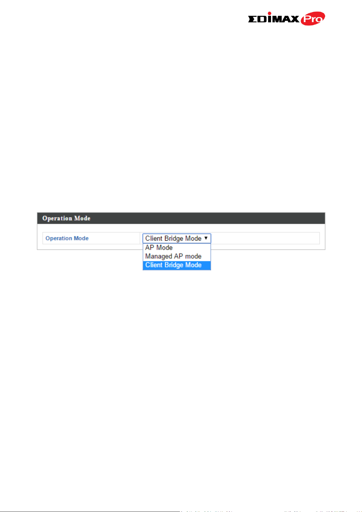
IV-6. Operation Mode
Operation Mode
AP Mode is a standard access point in a
wireless network.
Managed AP mode is an AP which is part of
the AP array and is managed by the
Controller AP.
Client Bridge mode is ideal for last mile
solutions.
Screenshots displayed are examples. The information shown on
your screen will vary depending on your configuration.
Your access point can function in three different modes.
The default mode for your access point is AP mode.
AP mode is a regular access point for use in your wireless network.
Managed AP mode acts as a “slave” AP within the AP array (controlled by the
AP Controller “master”).
In Client Bridge mode the OAP900 connects wirelessly to an AP’s SSID while
remaining in the same IP address range as that AP – the WAN and LAN are on
the same subnet. This is ideal for last-mile solutions.
In Managed AP mode some functions of the access point will be
disabled in this user interface and must be set using Edimax Pro
NMS on the AP Controller.
78
Page 82

V. Appendix
V-1. Configuring your IP address
The access point uses the default IP address 192.168.2.2. In order to access
the browser based configuration interface, you need to modify the IP address
of your computer to be in the same IP address subnet e.g. 192.168.2.x (x = 3 –
254).
The procedure for modifying your IP address varies across different operating
systems; please follow the guide appropriate for your operating system.
In the following examples we use the IP address 192.168.2.10 though you can
use any IP address in the range 192.168.2.x (x = 3 – 254).
If you changed the AP Controller’s IP address, or if your
gateway/router uses a DHCP server, ensure you enter the correct
IP address. Refer to your gateway/router’s settings. Your
computer’s IP address must be in the same subnet as the AP
Controller.
If using a DHCP server on the network, it is advised to use your
DHCP server’s settings to assign the AP Controller a static IP
address.
79
Page 83

V-1-1. Windows XP
1. Click the “Start” button (it should be located in the lower-left corner of
your computer), then click “Control Panel”. Double-click the “Network and
Internet Connections” icon, click “Network Connections”, and then
double-click “Local Area Connection”. The “Local Area Connection Status”
window will then appear, click “Properties”.
2. Select “Use the following IP address”, then input the following values:
IP address: 192.168.2.10
Subnet Mask: 255.255.255.0
Click ‘OK’ when finished.
80
Page 84

81
Page 85

V-1-2. Windows Vista
1. Click the “Start” button (it should be located in the lower-left corner of
your computer), then click “Control Panel”. Click “View Network Status and
Tasks”, then click “Manage Network Connections”. Right-click “Local Area
Network”, then select “Properties”. The “Local Area Connection Properties”
window will then appear, select “Internet Protocol Version 4 (TCP / IPv4)”,
and then click “Properties”.
2. Select “Use the following IP address”, then input the following values:
IP address: 192.168.2.10
Subnet Mask: 255.255.255.0
Click ‘OK’ when finished.
82
Page 86

83
Page 87

V-1-3. Windows 7
1. Click the “Start” button (it should be located in the lower-left corner of
your computer), then click “Control Panel”.
2. Under “Network and Internet” click “View network status and tasks”.
3. Click “Local Area Connection”.
84
Page 88

4. Click “Properties”.
85
Page 89

5. Select “Internet Protocol Version 4 (TCP/IPv4) and then click “Properties”.
6. Select “Use the following IP address”, then input the following values:
IP address: 192.168.2.10
Subnet Mask: 255.255.255.0
Click ‘OK’ when finished.
86
Page 90

87
Page 91

V-1-4. Windows 8
1. From the Windows 8 Start screen, you need to switch to desktop mode.
Move your curser to the bottom left of the screen and click.
2. In desktop mode, click the File Explorer icon in the bottom left of the
screen, as shown below.
88
Page 92

3. Right click “Network” and then select “Properties”.
4. In the window that opens, select “Change adapter settings” from the left
side.
89
Page 93

5. Choose your connection and right click, then select “Properties”.
6. Select “Internet Protocol Version 4 (TCP/IPv4) and then click “Properties”.
90
Page 94

7. Select “Use the following IP address”, then input the following values:
IP address: 192.168.2.10
Subnet Mask: 255.255.255.0
Click ‘OK’ when finished.
91
Page 95

V-1-5. Mac
1. Have your Macintosh computer operate as usual, and click on “System
Preferences”
2. In System Preferences, click on “Network”.
3. Click on “Ethernet” in the left panel.
4. Open the drop-down menu labeled “Configure IPv4” and select
“Manually”.
92
Page 96

5. Enter the IP address 192.168.2.10 and subnet mask 255.255.255.0. Click
on “Apply” to save the changes.
93
Page 97

COPYRIGHT
Copyright Edimax Technology Co., Ltd. all rights reserved. No part of this publication
may be reproduced, transmitted, transcribed, stored in a retrieval system, or translated
into any language or computer language, in any form or by any means, electronic,
mechanical, magnetic, optical, chemical, manual or otherwise, without the prior written
permission from Edimax Technology Co., Ltd.
Edimax Technology Co., Ltd. makes no representations or warranties, either expressed or
implied, with respect to the contents hereof and specifically disclaims any warranties,
merchantability, or fitness for any particular purpose. Any software described in this
manual is sold or licensed as is. Should the programs prove defective following their
purchase, the buyer (and not this company, its distributor, or its dealer) assumes the
entire cost of all necessary servicing, repair, and any incidental or consequential damages
resulting from any defect in the software. Edimax Technology Co., Ltd. reserves the right
to revise this publication and to make changes from time to time in the contents hereof
without the obligation to notify any person of such revision or changes.
The product you have purchased and the setup screen may appear slightly different from
those shown in this QIG. The software and specifications are subject to change without
notice. Please visit our website www.edimax.com for updates. All brand and product
names mentioned in this manual are trademarks and/or registered trademarks of their
respective holders.
94
Page 98

Federal Communication Commission Interference Statement
This equipment has been tested and found to comply with the limits for a Class B digital device, pursuant to Part
15 of FCC Rules. These limits are designed to provide reasonable protection against harmful interference in a
residential installation. This equipment generates, uses, and can radiate radio frequency energy and, if not
installed and used in accordance with the instructions, may cause harmful interference to radio communications.
However, there is no guarantee that interference will not occur in a particular installation. If this equipment does
cause harmful interference to radio or television reception, which can be determined by turning the equipment
off and on, the user is encouraged to try to correct the interference by one or more of the following measures:
1. Reorient or relocate the receiving antenna.
2. Increase the separation between the equipment and receiver.
3. Connect the equipment into an outlet on a circuit different from that to which the receiver is connected.
4. Consult the dealer or an experienced radio technician for help.
FCC Caution
This device and its antenna must not be co-located or operating in conjunction with any other antenna or
transmitter. This device complies with Part 15 of the FCC Rules. Operation is subject to the following two
conditions: (1) this device may not cause harmful interference, and (2) this device must accept any interference
received, including interference that may cause undesired operation. Any changes or modifications not expressly
approved by the party responsible for compliance could void the authority to operate equipment.
Federal Communications Commission (FCC) Radiation Exposure Statement
This equipment complies with FCC radiation exposure set forth for an uncontrolled environment. In order to avoid
the possibility of exceeding the FCC radio frequency exposure limits, human proximity to the antenna shall not be
less than 2.5cm (1 inch) during normal operation.
Federal Communications Commission (FCC) RF Exposure Requirements
SAR compliance has been established in the laptop computer(s) configurations with PCMCIA slot on the side near
the center, as tested in the application for certification, and can be used in laptop computer(s) with substantially
similar physical dimensions, construction, and electrical and RF characteristics. Use in other devices such as PDAs
or lap pads is not authorized. This transmitter is restricted for use with the specific antenna tested in the
application for certification. The antenna(s) used for this transmitter must not be co-located or operating in
conjunction with any other antenna or transmitter.
R&TTE Compliance Statement
This equipment complies with all the requirements of DIRECTIVE 1999/5/EC OF THE EUROPEAN PARLIAMENT AND
THE COUNCIL of March 9, 1999 on radio equipment and telecommunication terminal equipment and the mutual
recognition of their conformity (R&TTE). The R&TTE Directive repeals and replaces in the directive 98/13/EEC
(Telecommunications Terminal Equipment and Satellite Earth Station Equipment) As of April 8, 2000.
Safety
This equipment is designed with the utmost care for the safety of those who install and use it. However, special
attention must be paid to the dangers of electric shock and static electricity when working with electrical
equipment. All guidelines of this and of the computer manufacture must therefore be allowed at all times to
ensure the safe use of the equipment.
EU Countries Intended for Use
The ETSI version of this device is intended for home and office use in Austria, Belgium, Bulgaria, Cyprus, Czech,
Denmark, Estonia, Finland, France, Germany, Greece, Hungary, Ireland, Italy, Latvia, Lithuania, Luxembourg, Malta,
Netherlands, Poland, Portugal, Romania, Slovakia, Slovenia, Spain, Sweden, Turkey, and United Kingdom. The ETSI
version of this device is also authorized for use in EFTA member states: Iceland, Liechtenstein, Norway, and
Switzerland.
EU Countries Not Intended for Use
None
95
Page 99

EU Declaration of Conformity
English: This equipment is in compliance with the essential requirements and other relevant
provisions of Directive 1995/5/EC, 2009/125/EC, 2006/95/EC, 2011/65/EC.
Français: Cet équipement est conforme aux exigences essentielles et autres dispositions de la
directive 1995/5/CE, 2009/125/CE, 2006/95/CE, 2011/65/CE.
Čeština: Toto zařízení je v souladu se základními požadavky a ostatními příslušnými ustanoveními
směrnic 1995/5/ES, 2009/125/ES, 2006/95/ES, 2011/65/ES.
Polski: Urządzenie jest zgodne z ogólnymi wymaganiami oraz szczególnymi warunkami
określonymi Dyrektywą UE 1995/5/EC, 2009/125/EC, 2006/95/EC, 2011/65/EC..
Română: Acest echipament este în conformitate cu cerinţele esenţiale şi alte prevederi relevante ale
Directivei 1995/5/CE, 2009/125/CE, 2006/95/CE, 2011/65/CE.
Русский: Это оборудование соответствует основным требованиям и положениям Директивы
1995/5/EC, 2009/125/EC, 2006/95/EC, 2011/65/EC.
Magyar: Ez a berendezés megfelel az alapvető követelményeknek és más vonatkozó irányelveknek
(1995/5/EK, 2009/125/EK, 2006/95/EK, 2011/65/EK).
Türkçe: Bu cihaz 1995/5/EC, 2009/125/EC, 2006/95/EC, 2011/65/EC direktifleri zorunlu istekler ve
diğer hükümlerle ile uyumludur.
Українська: Обладнання відповідає вимогам і умовам директиви 1995/5/EC, 2009/125/EC,
2006/95/EC, 2011/65/EC.
Slovenčina: Toto zariadenie spĺňa základné požiadavky a ďalšie príslušné ustanovenia smerníc
1995/5/ES, 2009/125/ES, 2006/95/ES, 2011/65/ES.
Deutsch: Dieses Gerät erfüllt die Voraussetzungen gemäß den Richtlinien 1995/5/EC, 2009/125/EC,
2006/95/EC, 2011/65/EC.
Español: El presente equipo cumple los requisitos esenciales de la Directiva 1995/5/EC,
2009/125/EC, 2006/95/EC, 2011/65/EC.
Italiano: Questo apparecchio è conforme ai requisiti essenziali e alle altre disposizioni applicabili
della Direttiva 1995/5/CE, 2009/125/CE, 2006/95/CE, 2011/65/CE.
Nederlands: Dit apparaat voldoet aan de essentiële eisen en andere van toepassing zijnde bepalingen
van richtlijn 1995/5/EC, 2009/125/EC, 2006/95/EC, 2011/65/EC..
Português: Este equipamento cumpre os requesitos essênciais da Directiva 1995/5/EC, 2009/125/EC,
2006/95/EC, 2011/65/EC.
Norsk: Dette utstyret er i samsvar med de viktigste kravene og andre relevante regler i Direktiv
1995/5/EC, 2009/125/EC, 2006/95/EC, 2011/65/EC.
Svenska: Denna utrustning är i överensstämmelse med de väsentliga kraven och övriga relevanta
bestämmelser i direktiv 1995/5/EG, 2009/125/EG, 2006/95/EG, 2011/65/EG.
Dansk: Dette udstyr er i overensstemmelse med de væ sentligste krav og andre relevante
forordninger i direktiv 1995/5/EC, 2009/125/EC, 2006/95/EC, 2011/65/EC.
suomen kieli: Tämä laite täyttää direktiivien 1995/5/EY, 2009/125/EY, 2006/95/EY, 2011/65/EY
oleelliset vaatimukset ja muut asiaankuuluvat määräykset.
-----------------------------------------------------------------------------------------------------------------------
WEEE Directive & Product Disposal
At the end of its serviceable life, this product should not be treated as household or general waste. It
should be handed over to the applicable collection point for the recycling of electrical and electronic
equipment, or returned to the supplier for disposal.
96
Page 100

Declaration of Conformity
We, Edimax Technology Co., Ltd., declare under our sole responsibility, that the
equipment described below complies with the requirements of the European R&TTE
directives.
Equipment:
Outdoor Access Point
Model No.:
OAP900
The following European standards for essential requirements have been followed:
Directives 2014/53/EU
Spectrum
:
ETSI EN 300 328 V1.9.1 (2015-02);
ETSI EN 301 893 V1.8.1(2015-03)
EMC
:
EN 301 489-1 V1.9.2 (2011-09);
EN301 489-17 V2.2.1(2012-09);
EN 55022:2010/AC:2011
EN 55024:2010
Safety (LVD)
:
IEC 60950-1:2005 (2nd Edition)+Am 1:2009+Am 2:2013
EN 60950-1:2006+A11:2009+A1:2010+A12:2011+A2:2013
Recommendation 2014/53/EU
EMF
:
EN 62311:2008
Directives 2006/95/EC; 2014/35/EU
Safety (LVD)
:
IEC 60950-1:2005 (2nd Edition);Am 1:2009+Am2:2013
EN 60950-1:2006+A11+A:2010+A12:20+A2:2013
Edimax Technology Co., Ltd.
No. 3, Wu Chuan 3rd Road,
Wu-Ku Industrial Park,
New Taipei City, Taiwan
Date of Signature:
Jun, 2016
Signature:
Printed Name:
Albert Chang
Title:
Director
Edimax Technology Co., Ltd.
97
 Loading...