

Page 1

OAP1300
User Manual
03-2018 / v1.0
Page 2

CONTENTS
CONTENTS ....................................................................................... 2
OVERVIEW ...................................................................................... 5
I Product Information ................................................................... 6
I-1 Package Contents ............................................................................ 6
I-2 System Requirements ..................................................................... 7
I-3 Hardware Overview ........................................................................ 7
I-4 LED Status ....................................................................................... 8
I-5 Reset ............................................................................................... 9
II Quick Setup & Mode Selection .................................................. 10
II-1 Default Mode: Access Point Mode ............................................... 10
II-2 Repeater Mode ............................................................................. 13
II-3 Client Bridge Mode ....................................................................... 16
II-4 Managed AP Mode ....................................................................... 19
II-5 Basic Settings ................................................................................ 21
II-6 Wi-Fi Protected Setup (WPS) ........................................................ 26
III Hardware Installation .............................................................. 27
III-1 Antenna ........................................................................................ 27
III-2 Powering on the Access Point Outdoor ........................................ 28
III-3 Mounting ...................................................................................... 30
IV Browser Based Configuration Interface .................................... 32
2
Page 3

IV-1 Information ................................................................................... 34
IV-1-1 System Information .............................................................................. 34
IV-1-2 Wireless Clients .................................................................................... 37
IV-1-3 Wireless Monitor .................................................................................. 38
IV-1-4 DHCP Clients ......................................................................................... 39
IV-1-5 Log ........................................................................................................ 40
IV-2 Network Settings .......................................................................... 42
IV-2-1 LAN-Side IP Address .............................................................................. 42
IV-2-2 LAN Port ................................................................................................ 44
IV-2-3 IGMP Snooping ..................................................................................... 45
IV-2-4 STP Management .................................................................................. 46
IV-2-5 VLAN ..................................................................................................... 47
IV-3 Wireless Settings ........................................................................... 48
IV-3-1 2.4GHz 11bgn ........................................................................................ 48
IV-3-1-1 Basic ............................................................................................................. 49
IV-3-1-2 Advanced ..................................................................................................... 51
IV-3-1-3 Security ........................................................................................................ 53
IV-3-1-3-1 No Authentication / Additional Authentication ................................ 54
IV-3-1-3-2 WEP ...................................................................................................... 56
IV-3-1-3-3 IEEE802.1x/EAP ................................................................................... 56
IV-3-1-3-4 WPA-PSK .............................................................................................. 57
IV-3-1-3-5 WPA-EAP .............................................................................................. 58
IV-3-1-4 WDS ............................................................................................................. 59
IV-3-1-5 Guest Network ............................................................................................ 61
IV-3-2 5GHz 11ac 11an .................................................................................... 62
IV-3-2-1 Basic ............................................................................................................. 63
IV-3-2-2 Advanced ..................................................................................................... 65
IV-3-2-3 Security ........................................................................................................ 67
IV-3-2-4 WDS ............................................................................................................. 69
IV-3-2-5 Guest Network ............................................................................................ 71
IV-3-3 WPS ....................................................................................................... 72
IV-3-4 RADIUS .................................................................................................. 74
IV-3-4-1 RADIUS Settings .......................................................................................... 75
IV-3-4-2 Internal Server ............................................................................................. 77
IV-3-4-3 RADIUS Accounts ........................................................................................ 79
IV-3-5 MAC Filter ............................................................................................. 81
IV-3-6 WMM .................................................................................................... 83
IV-3-7 Schedule ............................................................................................... 85
IV-3-8 Traffic Shaping ...................................................................................... 87
3
Page 4

IV-3-9 Bandsteering ......................................................................................... 89
IV-4 Management ................................................................................. 90
IV-4-1 Admin ................................................................................................... 90
IV-4-2 Date and Time ...................................................................................... 93
IV-4-3 Syslog Server ......................................................................................... 95
IV-4-4 Ping Test ............................................................................................... 96
IV-4-5 I’m Here ................................................................................................ 97
IV-5 Advanced ...................................................................................... 98
IV-5-1 LED Settings .......................................................................................... 98
IV-5-2 Update Firmware .................................................................................. 99
IV-5-3 Save / Restore Settings ....................................................................... 101
IV-5-4 Factory Default ................................................................................... 102
IV-5-5 Reboot ................................................................................................ 103
IV-6 Operation Mode ......................................................................... 104
V Appendix ................................................................................ 105
V-1 Configuring your IP address ........................................................ 105
V-1-1 Windows XP ........................................................................................ 106
V-1-2 Windows Vista .................................................................................... 108
V-1-3 Windows 7 .......................................................................................... 110
V-1-4 Windows 8 .......................................................................................... 114
V-1-5 Mac ..................................................................................................... 118
V-2 Setting AP via ManageEngine MibBrowser with SNMPv3 -
Example .................................................................................................. 120
V-2-1 Setting in Web .................................................................................... 120
V-2-2 Setting Rule ......................................................................................... 121
V-2-3 Setting in ManageEngine MibBrowser ............................................... 121
VI Best Practice ........................................................................... 125
VI-1 How to Create and Link WLAN & Access Point Groups .............. 125
VI-1-1 Create WLAN Group ........................................................................... 125
VI-1-2 Create Access Point Group ................................................................. 128
VI-1-3 Assign Access Point Group to use the SSID group settings ................. 130
4
Page 5

OVERVIEW
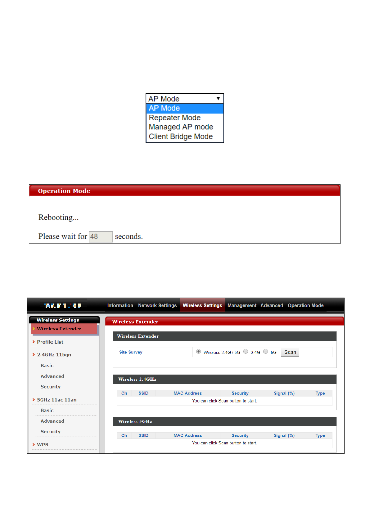
Your device can function in four different modes.
AP Mode is a regular access point for use in your wireless network. This is the
default mode of the access point.
Repeater Mode is a wireless repeater (also called wireless range extender)
that takes an existing signal from a wireless router or wireless access point
and rebroadcasts it to create a second network.
Managed AP Mode acts as a “slave” AP within an AP array (controlled by the
AP Controller “master”).
Client Bridge Mode determines the device to be a client bridge. The client
bridge receives wireless signal and provides it to devices connected to the
bridge via Ethernet cable.
5
Page 6

1
2
3
4
5
6
7
8
1. OAP1300 Access Point
2. Wall Mount Screw Template
3. Wall Mount Screw Set
4. CD
5. Quick Installation Guide
6. Ethernet Cable
7. Pole Mount Strap x2
8. Antenna x2
I Product Information
I-1 Package Contents
6
Page 7
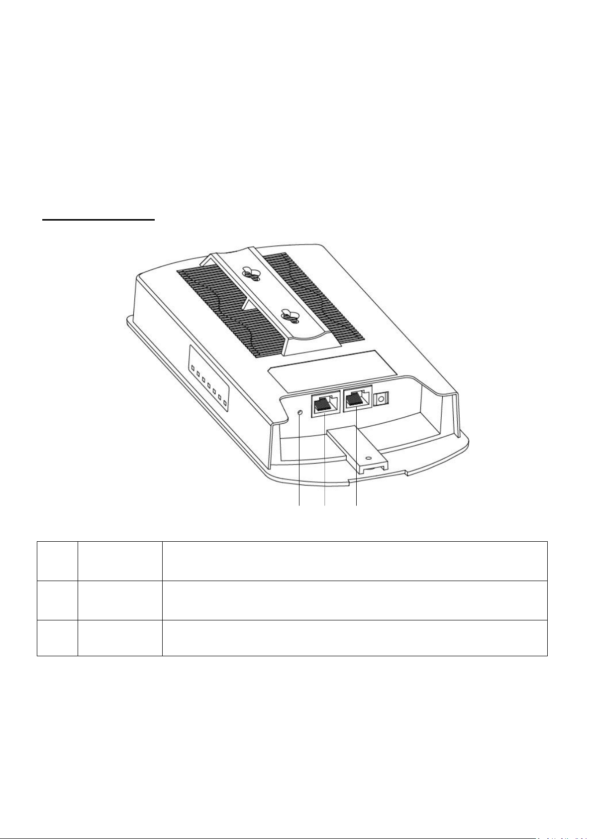
A
LAN 1
POE-IN
LAN port with Power over Ethernet (PoE) IN
B
LAN 2
POE-OUT
LAN port with PoE OUT
C
Reset
Reset Button
C B A
I-2 System Requirements
- Existing cable/DSL modem, PoE Switch & router
- Computer with web browser for access point configuration
I-3 Hardware Overview
Ports and Button
7
Page 8
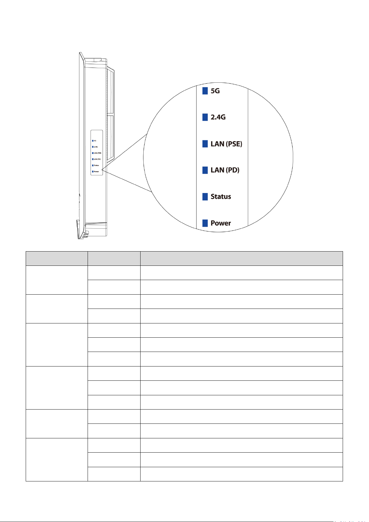
LED
LED Status
Description
5G
(WLAN)
On
Wireless enabled.
Off
Wireless disabled.
2.4G
(WLAN)
On
Wireless enabled.
Off
Wireless disabled.
LAN (PSE)
On
LAN port connected.
Flashing
Activity (transmitting and receiving).
Off
LAN port not connected.
LAN (PD)
On
LAN port connected.
Flashing
Activity (transmitting and receiving).
Off
LAN port not connected.
Status
On
Access point booting up.
Off
No occurred error.
Power
On
The access point is on.
Flashing
Upgrading firmware.
Off
The access point is off.
I-4 LED Status
8
Page 9
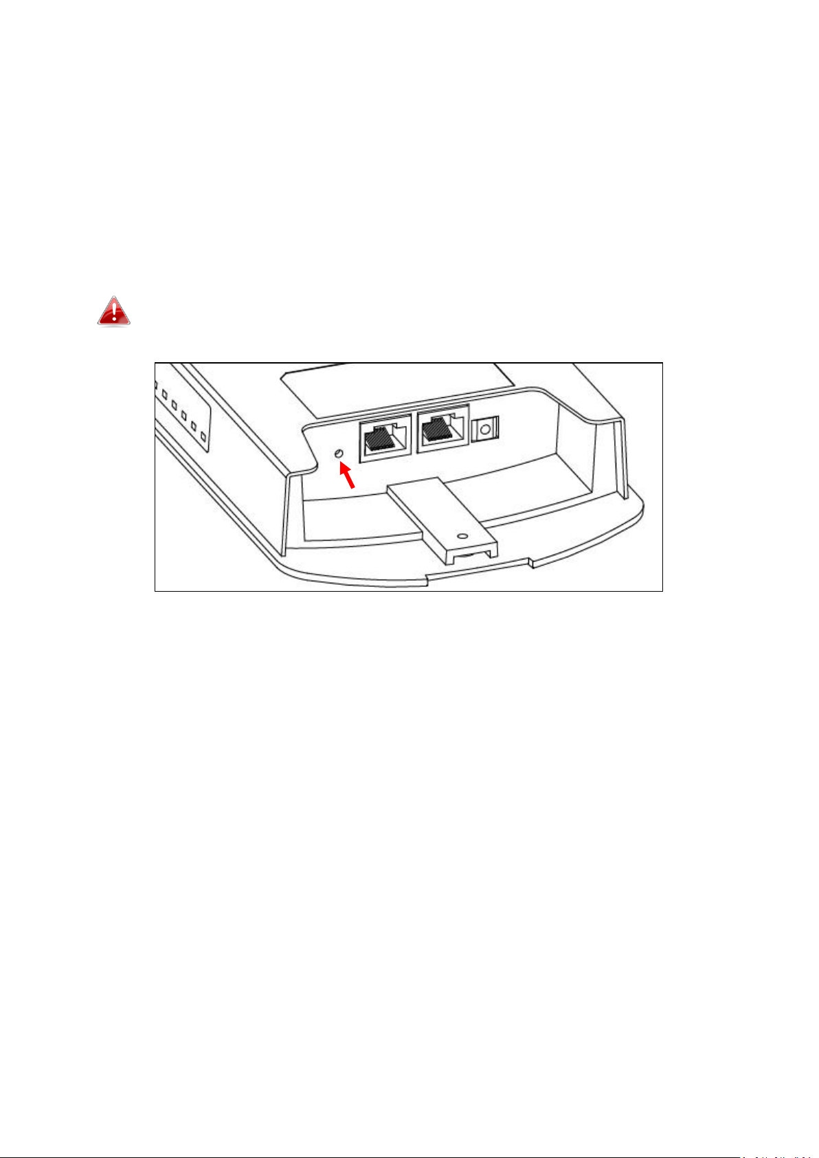
I-5 Reset
If you experience problems with your access point, you can reset the device
back to its factory settings. This resets all settings back to default.
1. Press and hold the reset button on the access point for at least 10
seconds then release the button.
You may need to use a pin or similar sharp object to push the reset
button.
2. Wait for the access point to restart. The access point is ready for setup
when the Power LED is turned on.
9
Page 10
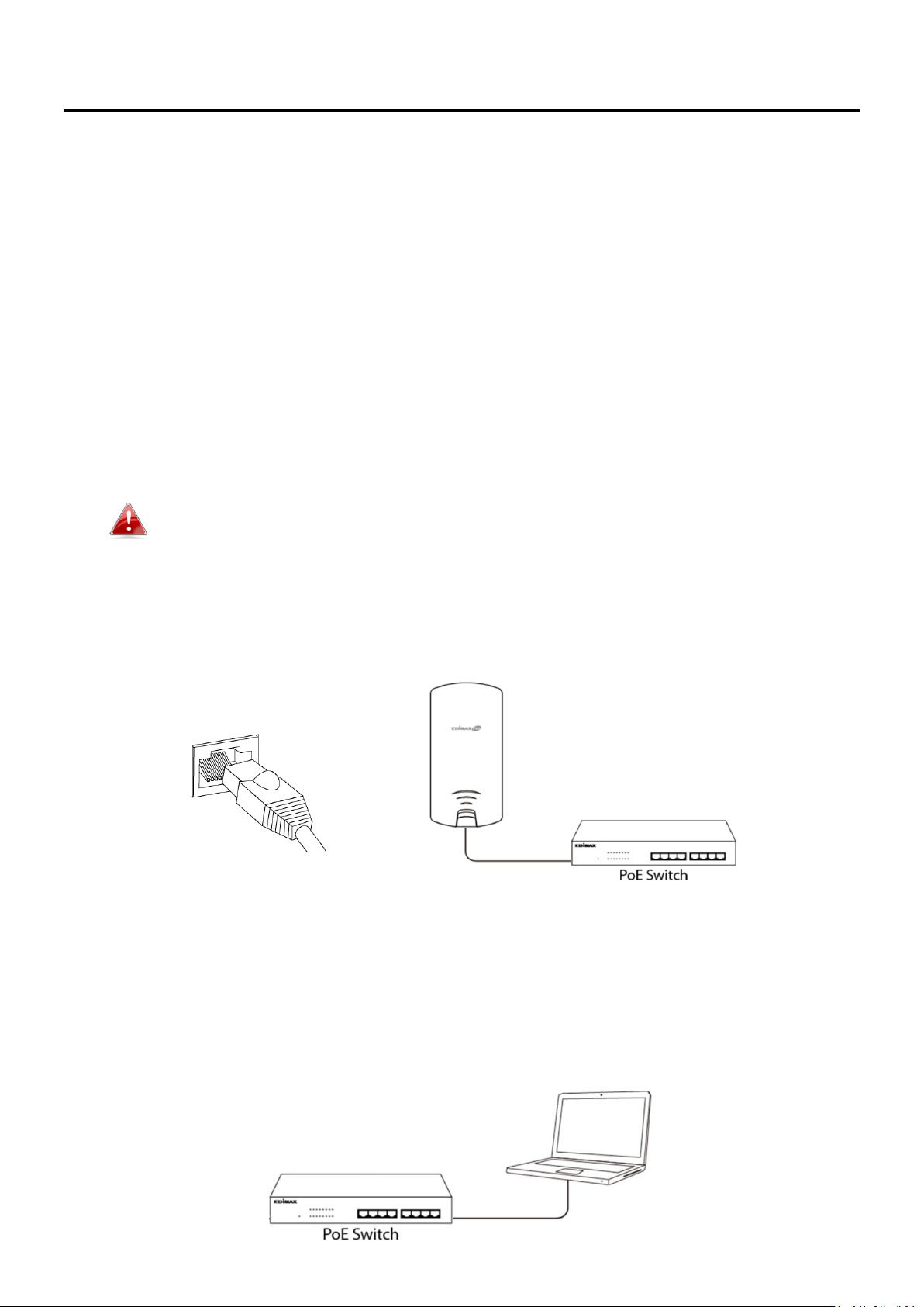
LAN 1 (PoE-In) Port
II Quick Setup & Mode Selection
The unit can function as a standalone access point (AP Mode), as a repeater
(Repeater Mode), as part of an AP array (Managed AP Mode), or as a client
bridge (Client Bridge Mode).
Follow the default mode steps below and select the desired operation mode.
II-1 Default Mode: Access Point Mode
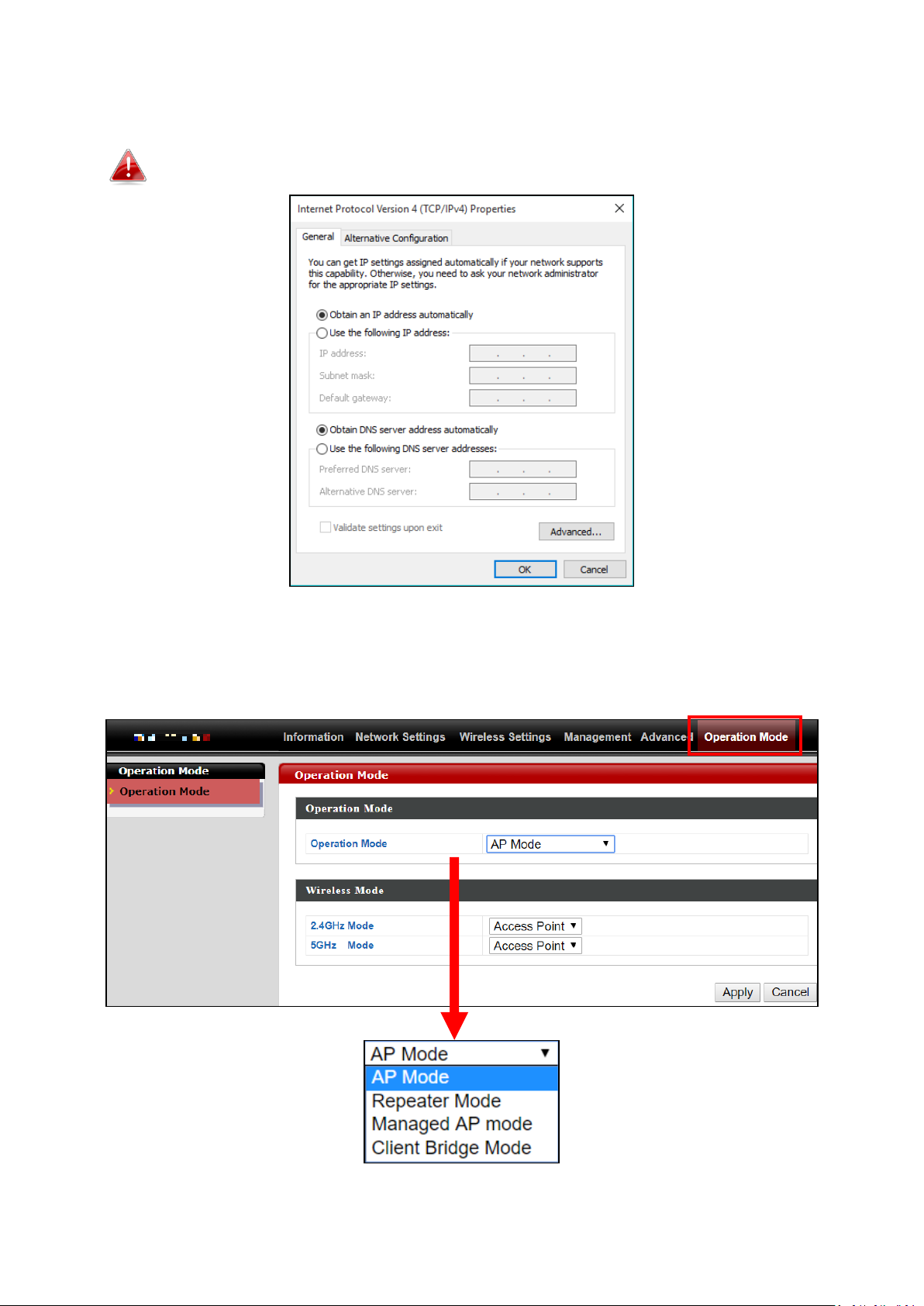
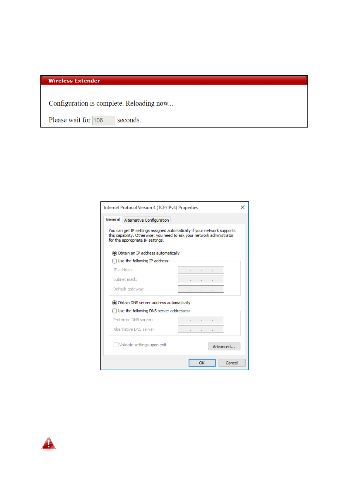
1. Set your computer’s IP address to 192.168.2.x where x is a number in
the range 3 – 100. If you are unsure how to do this, please refer to V-1
Configuring your IP address for more information.
Please ensure there are no other active network connections on your
computer by disabling Wi-Fi and other Ethernet connections.
2. Wire an Ethernet cable to the LAN 1 (PoE-In) port of the access point
and the PoE switch to power up the access point.
3. Please wait a moment for the device to start up. The device is ready
when the Power LED is turned on.
4. Connect a computer to the switch using an Ethernet cable.
10
Page 11
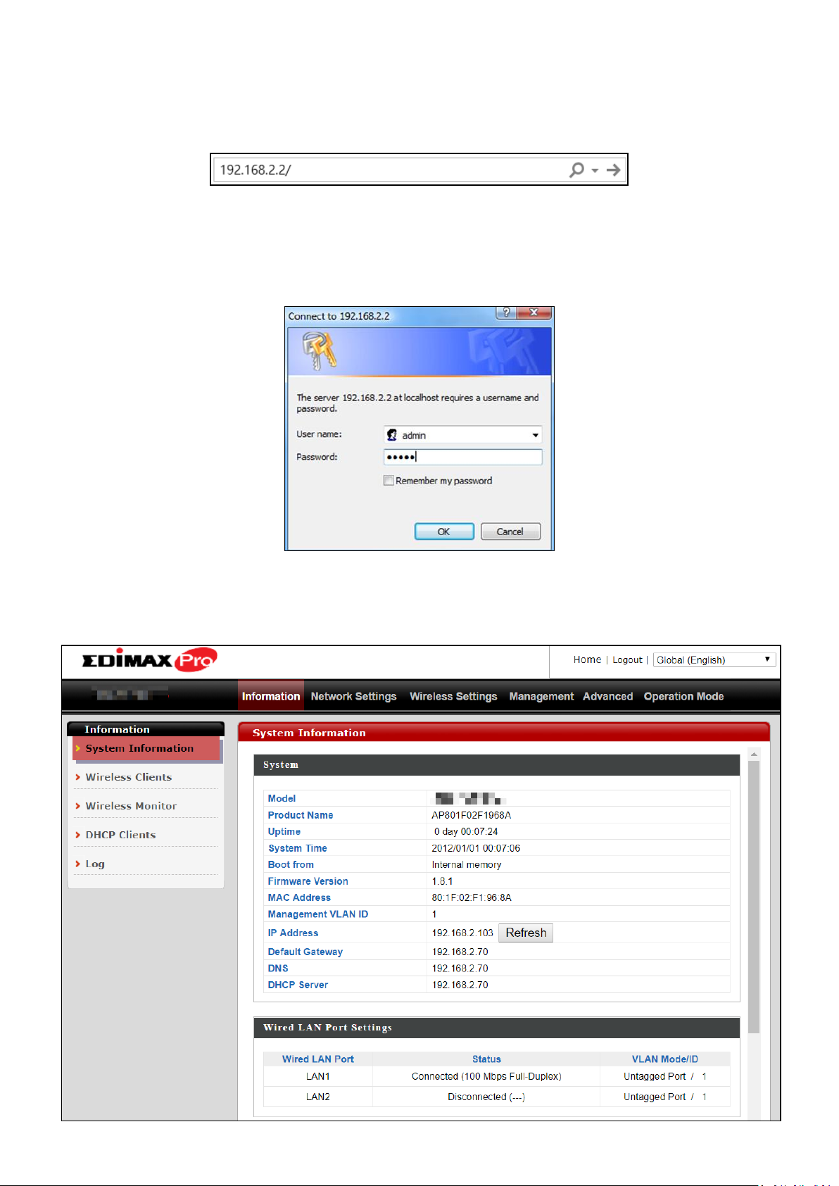
5. Enter the device’s default IP address 192.168.2.2 into the URL bar of a
web browser.
6. You will be prompted for a username and password. Enter the default
username “admin” and the default password “1234”.
7. “System Information” home screen will be shown:
11
Page 12
8. By default, the device is in AP Mode.
If you do not wish to change the operation mode, switch your computer
back to dynamic IP address now.
9. If you wish to change to a different operation mode, go to “Operation
Mode” tab to select the desired operation mode. Follow the steps in
the following sections to change the operation mode.
12
Page 13
II-2 Repeater Mode
From the default mode above,
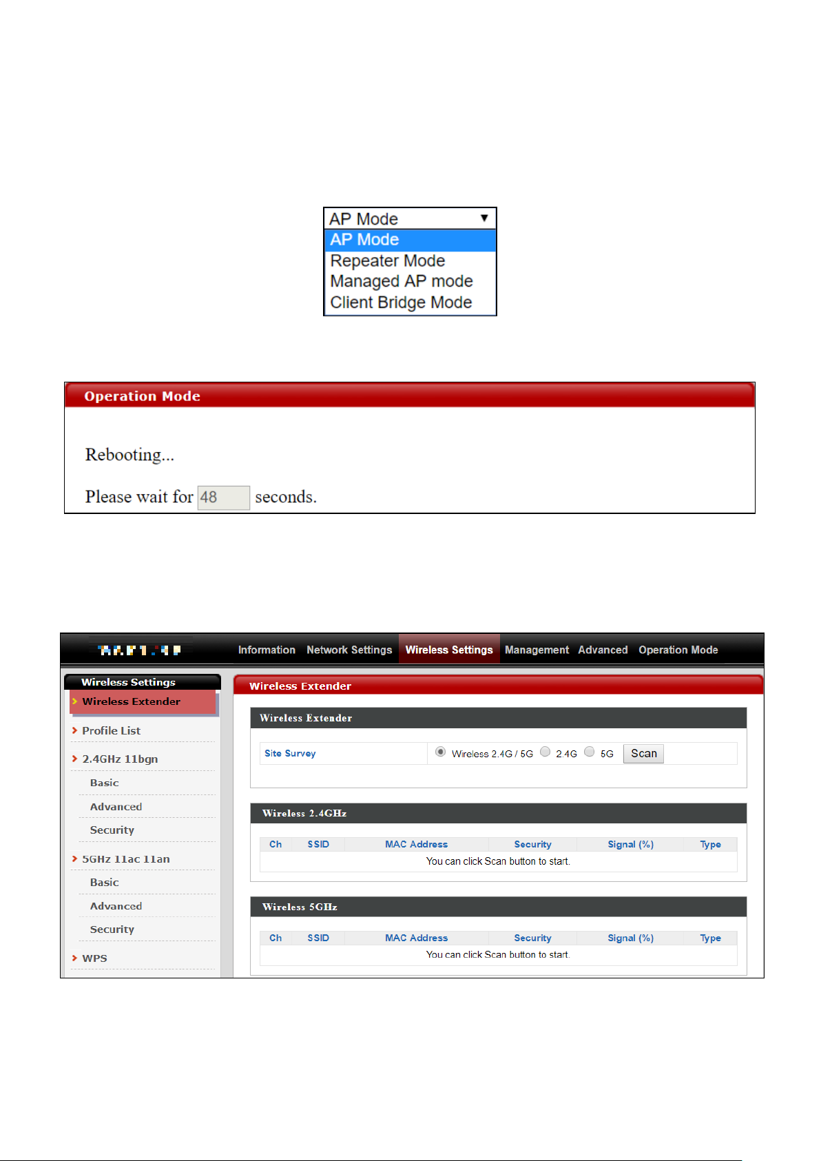
1. Select Repeater Mode from the operation mode drop down menu:
2. Press “Apply” and wait for the device to reboot into Repeater Mode:
3. When system page is displayed, go to Wireless Settings Wireless
Extender.
13
Page 14
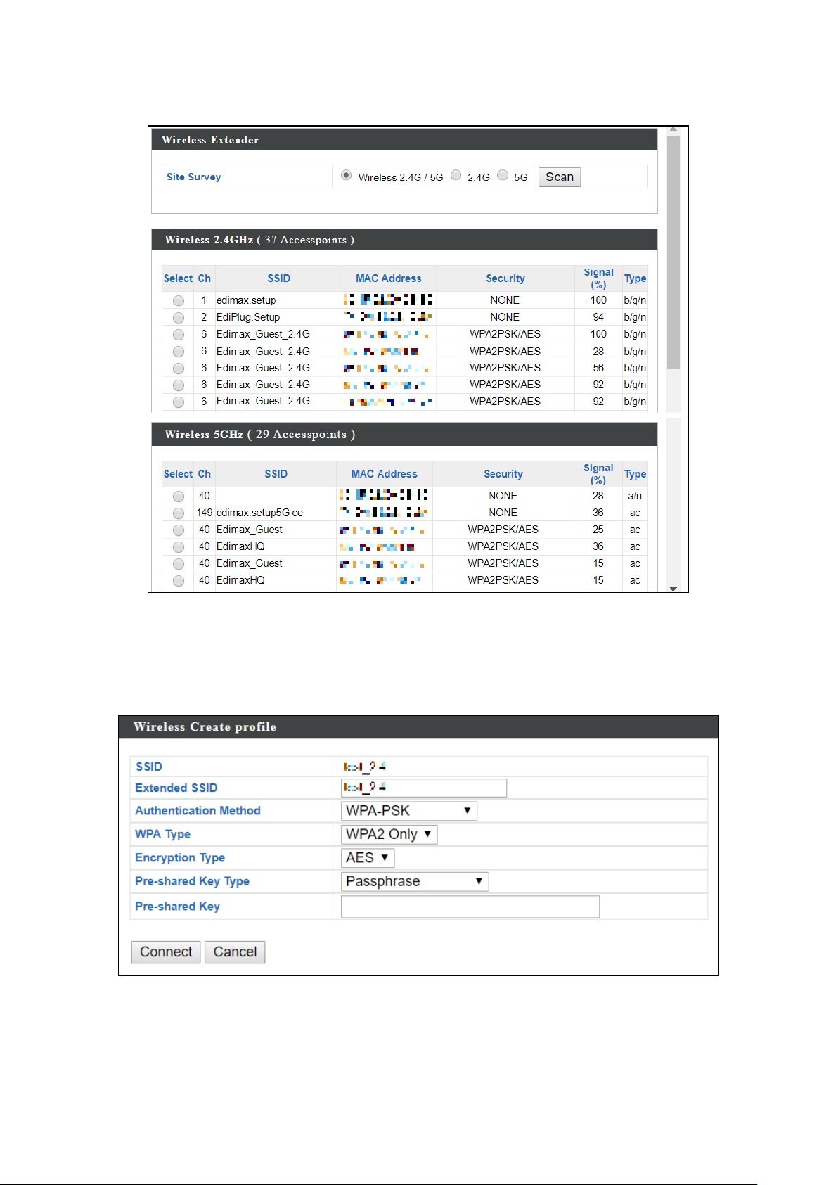
4. Click Scan to search for and display available SSIDs
5. Click the circle icon to connect to an available source SSID. SSIDs can be
configured independently for each frequency 2.4GHz & 5GHz.
14
Page 15
6. Edit the new extended SSID according to your preference and enter the
security details for the source SSID (e.g. Pre-shared Key). Click “Connect”
to proceed.
Wait for the configuration to take effect:
7. The device (now in Repeater Mode) will establish a connection to the
source SSID and repeat the extended SSID. The device will become a
DHCP client of the router/root AP. Switch your computer back to
dynamic IP address.
8. To access the web user interface, check your router/root AP’s settings
to determine the device’s new IP address. Enter the new IP address into
the browser for the web user interface.
If you wish to switch the operation mode, please reset the device to
factory default (via web user interface or hardware reset).
15
Page 16
II-3 Client Bridge Mode
From the default mode above,
1. Select Client Bridge Mode from the operation mode drop down menu:
2. Press “Apply” and wait for the device to reboot into Client Bridge
Mode:
3. When system page is displayed, go to Wireless Settings Wireless
Extender.
16
Page 17
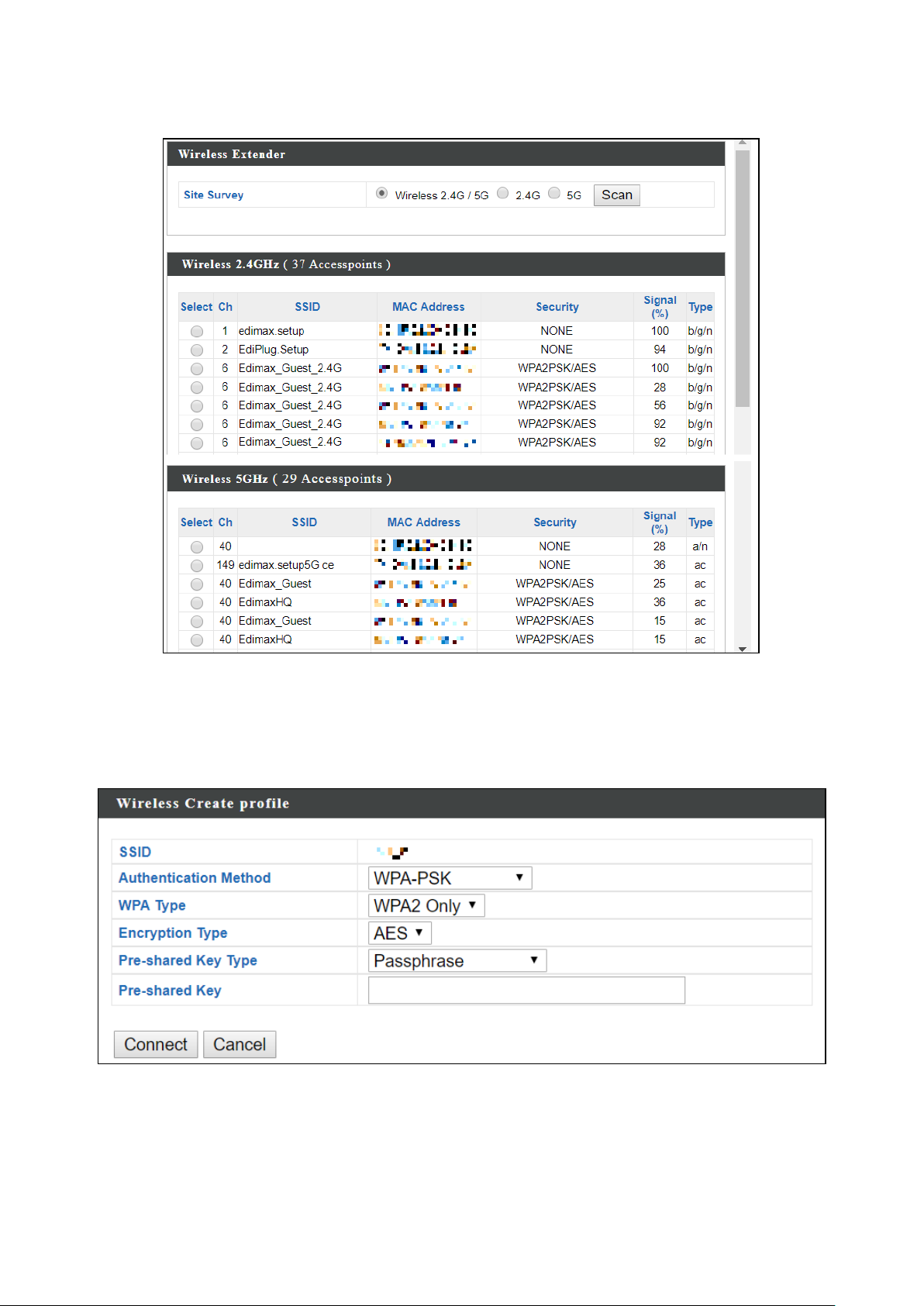
4. Click Scan to search for and display available SSIDs
5. Click the circle icon to connect to an available source SSID. SSIDs can be
configured independently for each frequency 2.4GHz & 5GHz.
17
Page 18

6. Edit according to your preference and enter the security details for the
source SSID (e.g. Pre-shared Key). Click “Connect” to proceed.
Wait for the configuration to take effect:
7. The device (now in Client Bridge Mode) will receive wireless signal and
provides it to devices connected to the bridge via Ethernet cable. The
device will become a DHCP client of the router/root AP. Switch your
computer back to dynamic IP address.
8. To access the web user interface, check your router/root AP’s settings
to determine the device’s new IP address. Enter the new IP address into
the browser for the web user interface.
If you wish to switch the operation mode, please reset the device to
factory default (via web user interface or hardware reset).
18
Page 19
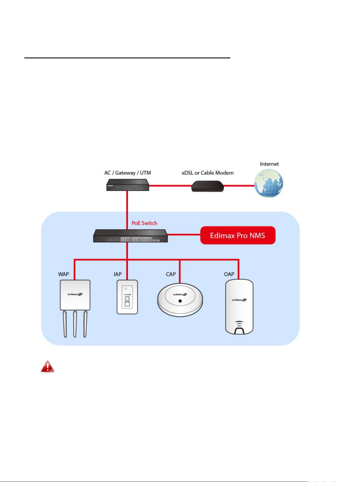
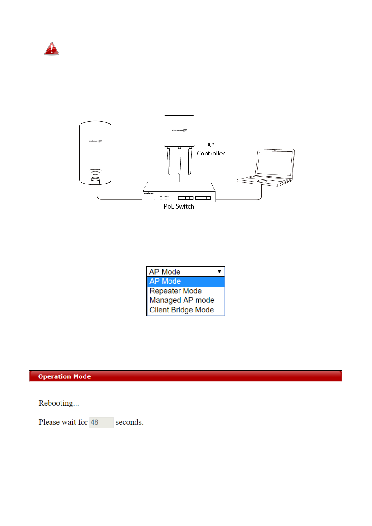
II-4 Managed AP Mode
Scenario: The Unit being managed by an AP Controller
The access point can be part of an AP Array by switching to “Managed AP
Mode”.
An AP Array is a group of access points centrally managed by an AP Controller,
where it can monitor, configure and manage all Managed APs.
An overview of the system is shown below:
By default, the access point will automatically switch mode if an AP
Controller is present in the network.
19
Page 20
To manually change to “Managed AP Mode”:
Ensure you have the latest firmware from the Edimax website for your
Edimax Pro products.
1. Connect an AP Controller to the switch currently connected to the
access point and computer.
2. From the default mode above, select Managed AP Mode from the
operation mode drop down menu:
3. Press “Apply” and wait for the device to reboot into Managed AP
Mode:
Wait for a few minutes for the settings to sync.
20
Page 21
II-5 Basic Settings
Basic settings of the access point are:
- LAN IP Address; and
- 2.4GHz & 5GHz SSID & Security; and
- Administrator Name & Password; and
- Time & Date
It is recommended that these settings are configured before using the
access point.
Whenever a new setting is applied to the access point, the webpage will
reload, as shown below:
Instructions below will help you configure these settings:
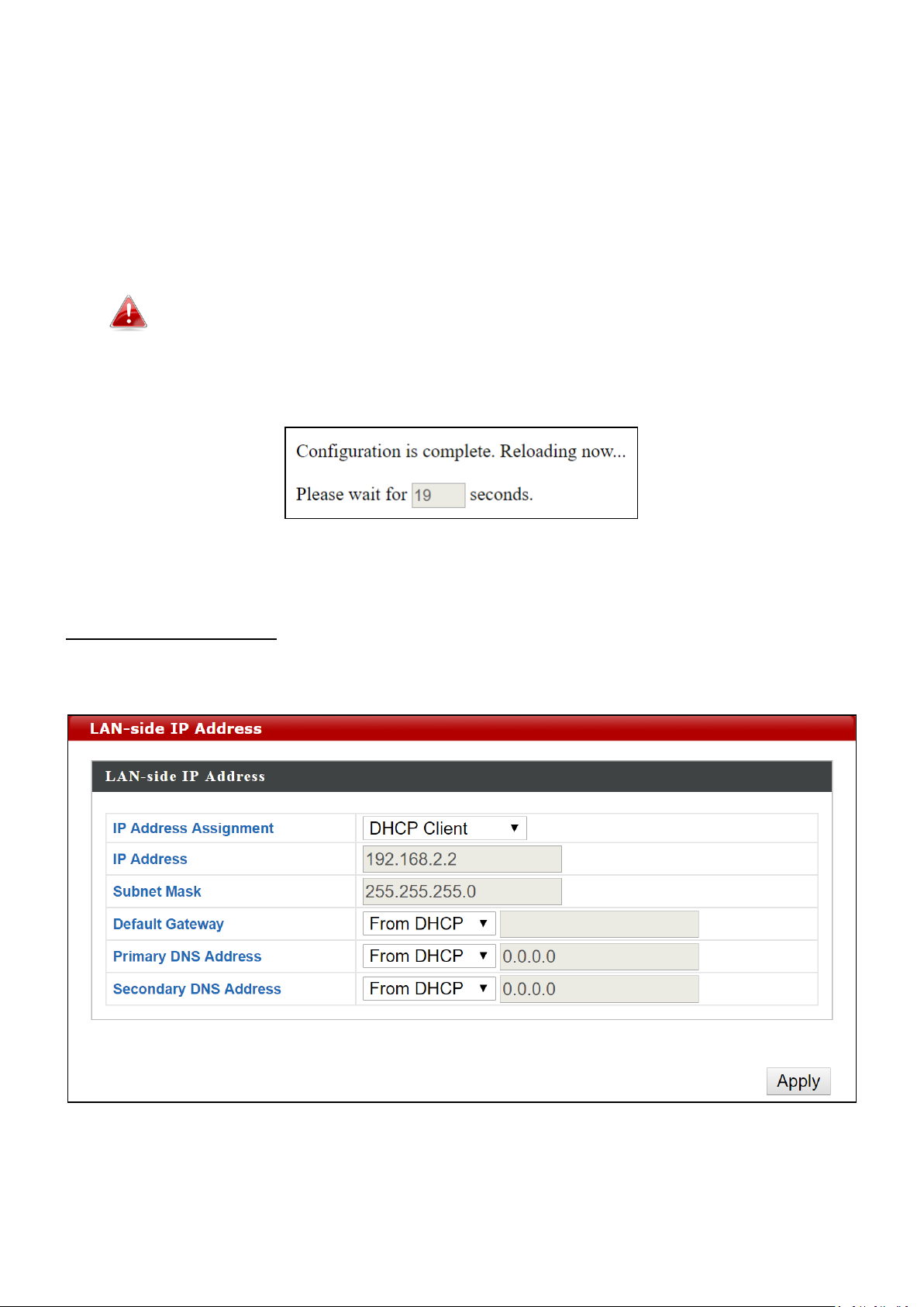
Changing IP Address:
1. Go to “Network Settings” > “LAN-side IP Address” for the screen
below:
21
Page 22
2. Enter the IP address settings you wish to use for your access point. You
can use a dynamic (DHCP) or static IP address, depending on your
network environment. Click “Apply” to save the changes and wait a few
moments for the access point to reload.
When you change your access point’s IP address, you need to use the
new IP address to access the browser based configuration interface
instead of the default IP 192.168.2.2.
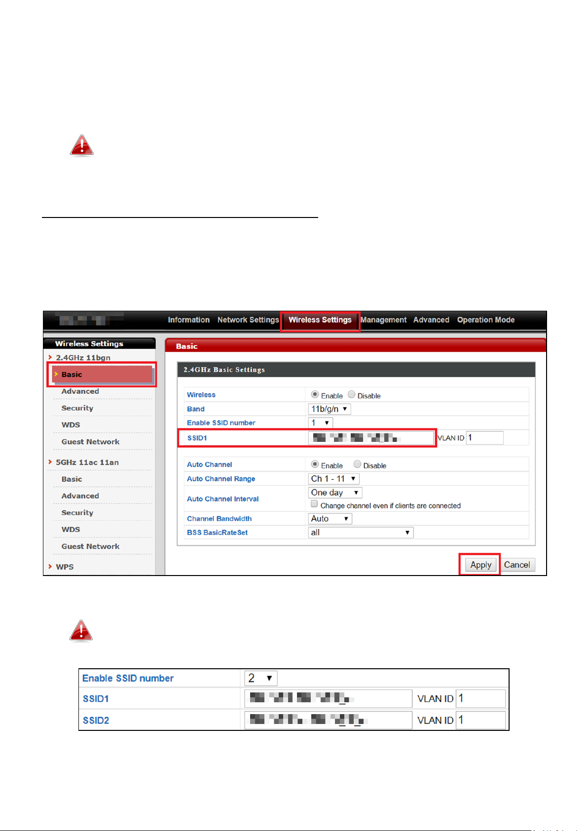
Changing SSID for 2.4GHz wireless network
1. Go to “Wireless Settings” > “2.4GHz 11bgn” > “Basic”.
2. Enter the new SSID for your 2.4GHz wireless network in the “SSID1”
field and click “Apply”.
To utilize multiple 2.4GHz SSIDs, open the drop down menu labelled
“Enable SSID number” and select how many SSIDs you require. Then
enter a new SSID in the corresponding numbered fields below, before
clicking “Apply”.
22
Page 23
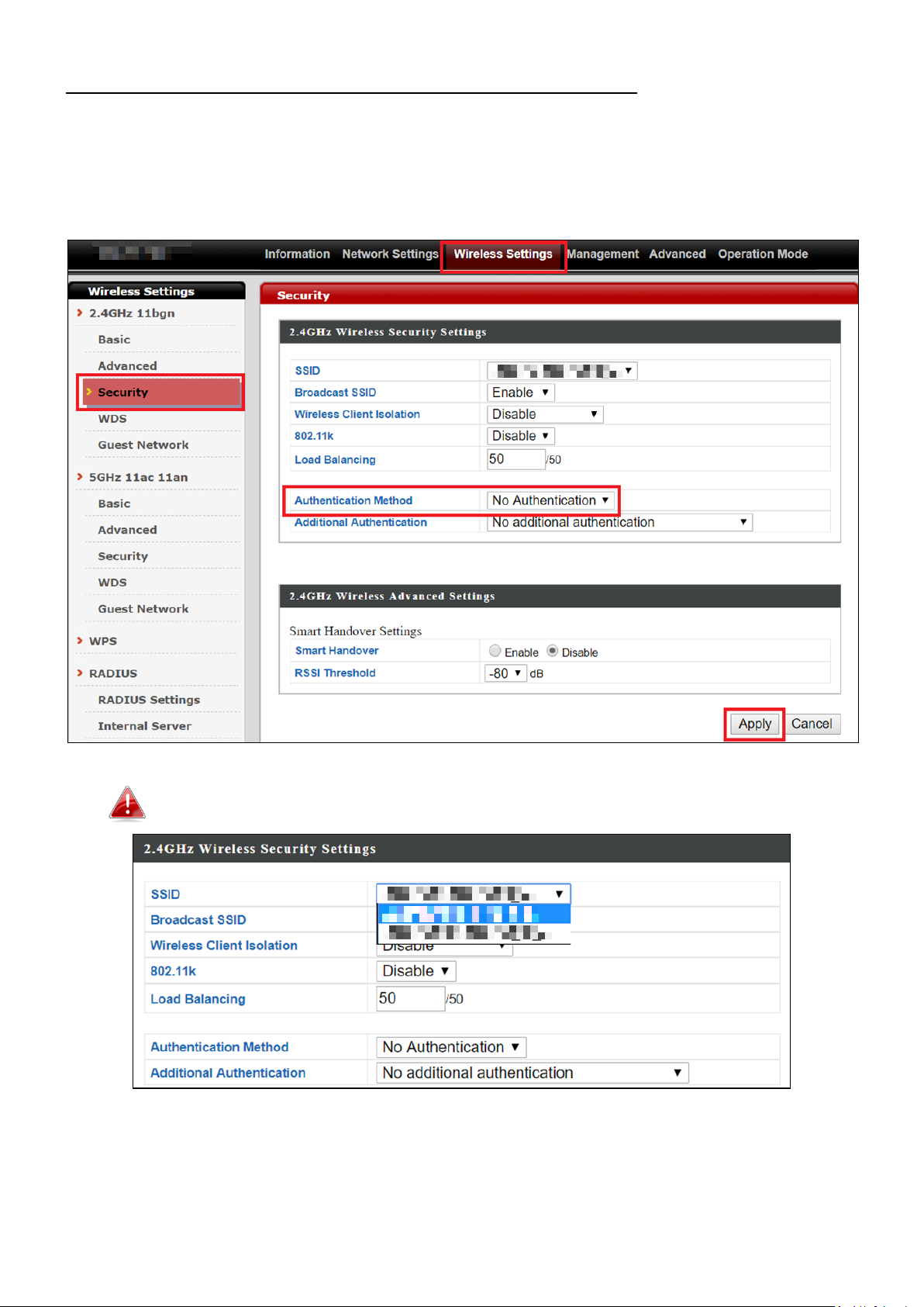
Configuring Security Settings of 2.4GHz wireless network
1. Go to “Wireless Settings” > “2.4GHz 11bgn” > “Security”.
2. Select an “Authentication Method”, enter or select fields where
appropriate, and click “Apply”.
If multiple SSIDs are used, specify which SSID to configure using the
“SSID” drop down menu.
23
Page 24
Changing SSID and Configuring Security Setting for 5GHz wireless network
Follow the steps outlined in “Changing SSID for 2.4GHz wireless network” and
“Configuring Security Setting for 2.4GHz wireless network” but choose the
5GHz option instead.
Changing Admin Name and Password
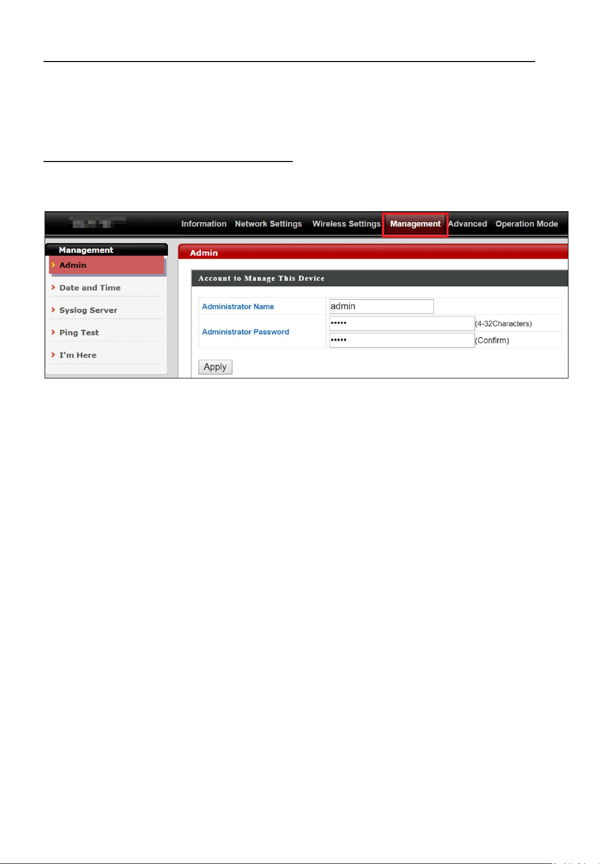
1. Go to “Management” > “Admin” as shown below:
2. Complete the “Administrator Name” and “Administrator Password”
fields and click “Apply”.
24
Page 25
Changing Date and Time
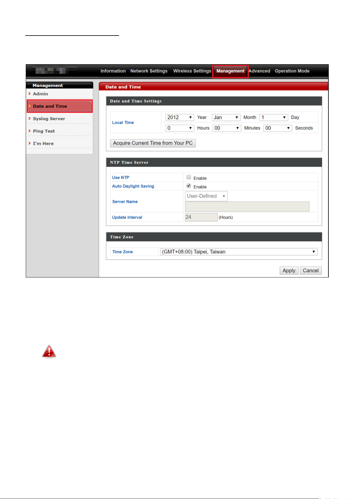
1. Go to “Management” > “Date and Time”.
2. Set the correct time and time zone for your access point using the drop
down menus. The access point also supports NTP (Network Time
Protocol) so, alternatively, you can enter the host name or IP address of
a time server. Click “Apply” when you are finished.
You can use the “Acquire Current Time from your PC” button if you wish
to set the access point to the same time as your PC.
The basic settings of your access point are now configured. Please refer to III
Hardware Installation for guidance on connecting your access point to a PoE
switch.
25
Page 26
II-6 Wi-Fi Protected Setup (WPS)
Wi-Fi Protected Setup is a simple way to establish connections between WPS
compatible devices. You can use the WPS button or the configuration
webpage activate the access point’s WPS function.
1. Go to “Wireless Settings” > “WPS” on your configuration webpage.
2. Check the checkbox of “Enable” and click “Apply”.
3. On the “Push-button WPS” line, click “Start” to activate WPS on the AP
for approximately 2 minutes.
(For more information on “WPS by PIN”, please refer to IV-3-3 WPS).
4. Within two minutes, activate WPS on your WPS-compatible wireless
device. Please check the documentation of your wireless device for
information regarding its WPS function.
5. The devices will establish a connection.
26
Page 27

SMA Connectors
III Hardware Installation
After finishing the above setup processes, you may relocate the access point
to the desired location.
III-1 Antenna
The antennae must be screwed onto the access point.
Please screw both antennae on clock-wise onto the SMA connectors as
demonstrated below:
27
Page 28
LAN 1 (PoE-In) Port
Removed Underside Cap
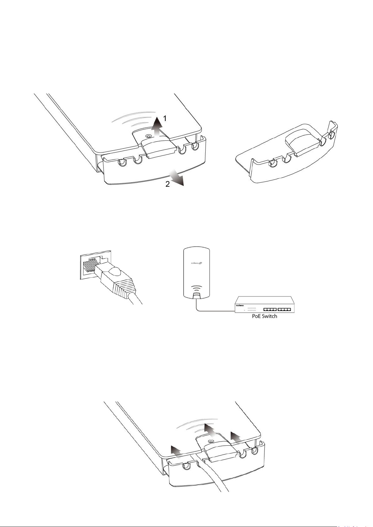
III-2 Powering on the Access Point Outdoor
1. Remove the cap from the underside of the access point by 1) pulling
the hook upwards, and 2) pulling the cap downward, as shown below:
2. Wire an Ethernet cable to the LAN 1 (PoE-In) port of the access point
and the PoE switch to power up the access point.
3. The access point will be powered by the PoE switch. Connect another
Ethernet cable to LAN 2 where necessary.
4. Replace the cap and allow the cable(s) to rest in the arch(es) of the cap.
28
Page 29

Click
5. Let the hook click with the access point and make sure it does not come
off easily. The cap serves as a rain-proof design suitable for use in the
open.
29
Page 30
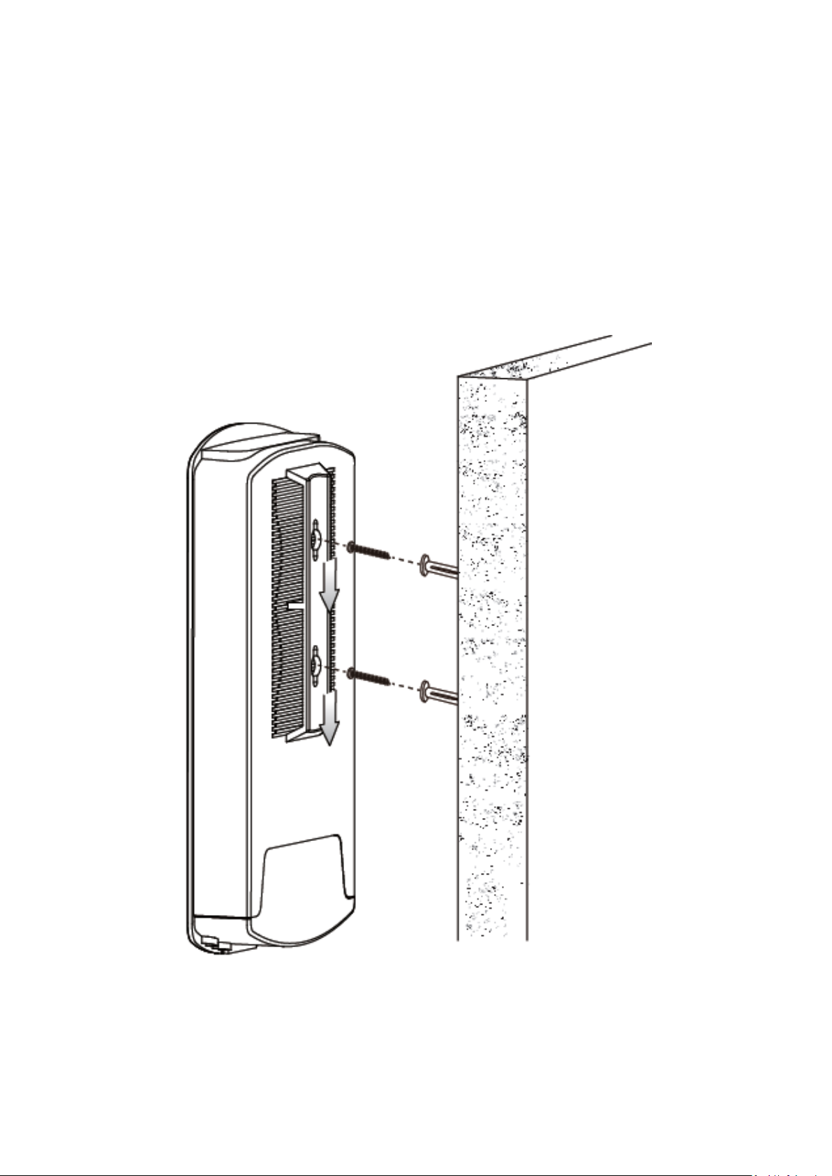
III-3 Mounting
After powering up the access point, mount it according to the desired
mounting options: Wall or Pole Mount
Wall Mount
Attach the mount and access point to a wall using the included wall mount
template and wall mount screw sets.
30
Page 31

Pole Mount
Fix the mount and access point to a pole using the included pole mount
straps.
31
Page 32

IV Browser Based Configuration Interface
Some functions of the browser based configuration interface are
disabled for different mode settings, please refer to the sections
applicable for your desired mode.
The browser-based configuration interface enables you to configure the
device’s advanced features. The OAP1300 features a range of advanced
functions such as MAC filtering, MAC RADIUS authentication, VLAN
configurations, up to 32 SSIDs and many more. To access the browser based
configuration interface:
1. Connect a computer to your access point using an Ethernet cable.
2. Enter your access point’s IP address in the URL bar of a web browser.
The access point’s default IP address is 192.168.2.2.
3. You will be prompted for a username and password. The default
username is “admin” and the default password is “1234”, though it was
recommended that you change the password during setup (see II-5
Basic Settings).
If you cannot remember your password, reset the access point back to its
factory default settings. Refer to 0
Reset.
32
Page 33

4. You will arrive at the “System Information” screen shown below.
5. Use the menu across the top and down the left side to navigate.
6. Where applicable, click “Apply” to save changes and reload the access
point, or “Cancel” to cancel changes.
Please wait a few seconds for the access point to reload after you “Apply”
changes. A countdown will be shown as exemplified below.
33
Page 34

7. Please refer to the following chapters for full descriptions of the
browser based configuration interface.
34
Page 35

IV-1 Information
IV-1-1 System Information
“System Information” page displays basic system information.
35
Page 36

System
Model
Displays the model number of the access point.
Product Name
Displays the product name for reference, which consists of
“AP” plus the MAC address.
Uptime
Displays the total time since the device was turned on.
System Time
Displays the system time.
Boot From
Displays information for the booted hardware, booted from
internal memory.
Firmware
Version
Displays the firmware version.
MAC Address
Displays the access point’s MAC address.
Management
VLAN ID
Displays the management VLAN ID.
IP Address
Displays the IP address of this device. Click “Refresh” to
update this value.
Default
Gateway
Displays the IP address of the default gateway.
DNS
IP address of DNS (Domain Name Server)
DHCP Server
IP address of DHCP Server.
Wired LAN Port Settings
Wired LAN
Port
Specifies which LAN port (1 or 2).
Status
Displays the status of the specified LAN port (connected or
disconnected).
VLAN Mode/ID
Displays the VLAN mode (tagged or untagged) and VLAN ID
for the specified LAN port. See IV-2-5 VLAN.
Wireless 2.4GHz (5GHz)
Status
Displays the status of the 2.4GHz or 5GHz wireless (enabled
or disabled).
MAC Address
Displays the access point’s MAC address.
Channel
Displays the channel number the specified wireless
frequency is using for broadcast.
Transmit
Power
Displays the wireless radio transmit power level as a
percentage.
RSSI
Received Signal Strength Indicator (RSSI) is a measurement
of the power present in a received radio signal.
36
Page 37

Wireless 2.4GHZ (5GHz) / SSID
SSID
Displays the SSID name(s) for the specified frequency.
Authentication
Method
Displays the authentication method for the specified SSID.
See IV-3 Wireless Settings.
Encryption
Type
Displays the encryption type for the specified SSID. See IV-3
Wireless Settings.
VLAN ID
Displays the VLAN ID for the specified SSID. See IV-2-5 VLAN.
Additional
Authentication
Displays the additional authentication type for the specified
SSID. See IV-3 Wireless Settings.
Wireless Client
Isolation
Displays whether wireless client isolation is in use for the
specified SSID. See IV-2-5 VLAN.
Wireless 2.4GHZ (5GHz) / WDS Status
MAC Address
Displays the peer access point’s MAC address.
Encryption
Type
Displays the encryption type for the specified WDS. See
IV-3-1-4 WDS.
VLAN Mode/ID
Displays the VLAN ID for the specified WDS. See IV-3-1-4
WDS.
Select “Refresh” to refresh all information.
37
Page 38

Refresh time
Auto Refresh
Time
Select a time interval for the client table list to automatically
refresh.
Manual
Refresh
Click refresh to manually refresh the client table.
2.4GHz (5GHz) WLAN Client Table
SSID
Displays the SSID which the client is connected to.
MAC Address
Displays the MAC address of the client.
Tx
Displays the total data packets transmitted by the specified
client.
Rx
Displays the total data packets received by the specified
client.
Signal (%)
Displays the wireless signal strength for the specified client.
Connected
Time
Displays the total time the wireless client has been
connected to the access point.
Idle Time
Client idle time is the time for which the client has not
transmitted any data packets i.e. is idle.
Vendor
The vendor of the client’s wireless adapter is displayed here.
IV-1-2 Wireless Clients
“Wireless Clients” page displays information about all wireless clients
connected to the device on the 2.4GHz or 5GHz frequency.
38
Page 39

Wireless Monitor
Site Survey
Select which frequency (or both) to scan, and click “Scan” to
begin.
Channel
Survey Result
After a scan is complete, click “Export” to save the results to
local storage.
Site Survey Results
Ch
Displays the channel number used by the specified SSID.
SSID
Displays the SSID identified by the scan.
MAC Address
Displays the MAC address of the wireless router/access point
for the specified SSID.
Security
Displays the authentication/encryption type of the specified
SSID.
Signal (%)
Displays the current signal strength of the SSID.
Type
Displays the 802.11 wireless networking standard(s) of the
specified SSID.
Vendor
Displays the vendor of the wireless router/access point for the
specified SSID.
IV-1-3 Wireless Monitor
“Wireless Monitor” is a tool built into the device to scan and monitor the
surrounding wireless environment. Select a frequency and click “Scan” to
display a list of all SSIDs within range along with relevant details for each SSID.
39
Page 40

IV-1-4 DHCP Clients
“DHCP Clients” shows information of DHCP leased clients.
40
Page 41

Save
Click to save the log as a file on your local computer.
Clear
Clear all log entries.
Refresh
Refresh the current log.
IV-1-5 Log
“System log” displays system operation information such as up time and
connection processes. This information is useful for network administrators.
Older entries will be overwritten when the log is full
The following information/events are recorded by the log:
USB
Mount & unmount
Wireless Client
Connected & disconnected
Key exchange success & fail
Authentication
Authentication fail or successful.
Association
Success or fail
WPS
M1 - M8 messages
WPS success
41
Page 42

Change Settings
System Boot
Displays current model name
NTP Client
Wired Link
LAN Port link status and speed status
Proxy ARP
Proxy ARP module start & stop
Bridge
Bridge start & stop.
SNMP
SNMP server start & stop.
HTTP
HTTP start & stop.
HTTPS
HTTPS start & stop.
SSH
SSH-client server start & stop.
Telnet
Telnet-client server start or stop.
WLAN (2.4G)
WLAN (2.4G] channel status and country/region status
WLAN (5G)
WLAN (5G) channel status and country/region status
42
Page 43

LAN-side IP Address
IP Address
Assignment
Select “DHCP Client” for your access point to be assigned a
dynamic IP address from your router’s DHCP server.
Select “Static IP” to manually specify a static/fixed IP address
for your access point (below).
Select “DHCP Server” for your access point to assign a
dynamic IP address to your PC. You will have to set a Primary
DNS address and a Secondary DNS address. For example,
Google’s Primary DNS address is 8.8.4.4 and Secondary DNS
address is 8.8.8.8.
IV-2 Network Settings
IV-2-1 LAN-Side IP Address
“LAN-side IP address” page allows you to configure your access point on your
Local Area Network (LAN). You can enable the access point to dynamically
receive an IP address from your router’s DHCP server or you can specify a
static IP address for your access point, as well as configure DNS servers.
The access point’s default IP address is 192.168.2.2.
43
Page 44

IP Address
Specify the IP address here. This IP address will be assigned to
your access point and will replace the default IP address.
Subnet Mask
Specify a subnet mask. The default value is 255.255.255.0
Default
Gateway
For DHCP users, select “From DHCP” to get default gateway
from your DHCP server or “User-Defined” to enter a gateway
manually. For static IP users, the default value is blank.
Primary DNS
Address
DHCP users can select “From DHCP” to get primary DNS
server’s IP address from DHCP or “User-Defined” to manually
enter a value. For static IP users, the default value is blank.
Secondary
DNS Address
Users can manually enter a value when DNS server’s primary
address is set to “User-Defined”.
DHCP users can select to get DNS servers’ IP address from DHCP or manually
enter a value. For static IP users, the default value is blank.
Press “Apply” to confirm the settings.
44
Page 45

Wired LAN
Port
Identifies LAN port 1 or 2.
Enable
Enable/disable specified LAN port.
Speed &
Duplex
Select a speed & duplex type for specified LAN port, or use
the “Auto” value. LAN ports can operate up to 1000Mbps and
full-duplex enables simultaneous data packets
transfer/receive.
Flow Control
Enable/disable flow control. Flow control can pause new
session request until current data processing is complete, in
order to avoid device overloads under heavy traffic.
802.3az
Enable/disable 802.3az. 802.3az is an Energy Efficient
Ethernet feature which disables unused interfaces to reduce
power usage.
IV-2-2 LAN Port
“LAN Port” page allows you to configure the settings for your access point’s
two wired LAN (Ethernet) ports.
Press “Apply” to confirm the settings.
45
Page 46

IV-2-3 IGMP Snooping
IGMP snooping is the process of listening to Internet Group Management
Protocol (IGMP) network traffic. The feature allows a network switch to listen
in on the IGMP conversation between hosts and routers. By listening to these
conversations the switch maintains a map of which links IP multicast streams.
Multicasts may be filtered from the links which do not need them and thus
controls which ports receive specific multicast traffic.
This page allows you to enable/disable this feature.
Press “Apply” to confirm the settings.
46
Page 47

IV-2-4 STP Management
When enabled, STP ensures that you do not create loops when you have
redundant paths in your network (as loops are deadly to a network).
This page allows you to enable / disable STP management.
Press “Apply” to confirm the settings.
47
Page 48

VLAN Interface
Wired LAN
Port/Wireless
Identifies LAN port 1 or 2 and wireless SSIDs.
VLAN Mode
Select “Tagged Port” or “Untagged Port” for specified LAN
interface.
VLAN ID
Set a VLAN ID for specified interface, if “Untagged Port” is
selected.
Management VLAN
VLAN ID
Specify the VLAN ID of the management VLAN. Only the hosts
belonging to the same VLAN can manage the device.
IV-2-5 VLAN
“VLAN” (Virtual Local Area Network) enables you to configure VLAN settings.
A VLAN is a local area network which maps workstations virtually instead of
physically and allows you to group together or isolate users from each other.
VLAN IDs in the range 1 – 4095 are supported.
Press “Apply” to confirm the settings.
48
Page 49

IV-3 Wireless Settings
IV-3-1 2.4GHz 11bgn
The “2.4GHz 11bgn” menu allows you to view and configure information for
your access point’s 2.4GHz wireless network across five categories: Basic,
Advanced, Security, WDS & Guest Network.
49
Page 50

Wireless
Enable or disable the access point’s 2.4GHz wireless radio.
When disabled, no 2.4GHz SSIDs will be active.
Band
Wireless standard used for the access point.
Combinations of 802.11b, 802.11g & 802.11n can be selected.
Enable SSID
Number
Select how many SSIDs to enable for the 2.4GHz frequency
from the drop down menu. A maximum of 16 can be enabled.
SSID#
Enter the SSID name for the specified SSID (up to 16). The SSID
can consist of any combination of up to 32 alphanumeric
characters.
VLAN ID
Specify a VLAN ID for each SSID.
Auto
Channel
Enable/disable auto channel selection.
Enable: Auto channel selection will automatically set the
wireless channel for the access point’s 2.4GHz frequency based
on availability and potential interference.
Disable: Select a channel manually as shown in the next table.
IV-3-1-1 Basic
The “Basic” screen displays basic settings for your access point’s 2.4GHz Wi-Fi
network (s).
50
Page 51

Auto
Channel
Range
Select a range to which auto channel selection can choose
from.
Auto
Channel
Interval
Select a time interval for how often the auto channel setting
will check/reassign the wireless channel.
Check/uncheck the “Change channel even if clients are
connected” box according to your preference.
Channel
Bandwidth
Select the channel bandwidth:
20MHz (lower performance but less interference); or
40MHz (higher performance but potentially higher
interference); or
Auto (automatically select based on interference level).
BSS
BasicRateSet
Set a Basic Service Set (BSS) rate: this is a series of rates to
control communication frames for wireless clients.
Channel
Select a wireless channel from 1 – 11.
Channel
Bandwidth
Set the channel bandwidth:
20MHz (lower performance but less interference); or
40MHz (higher performance but potentially higher
interference); or
Auto (automatically select based on interference level).
BSS
BasicRateSet
Set a Basic Service Set (BSS) rate: this is a series of rates to
control communication frames for wireless clients.
When auto channel is disabled, configurable fields will change. Select a
wireless channel manually:
Press “Apply” to apply the configuration, or “Cancel” to forfeit the changes.
51
Page 52

Contention
Slot
Select “Short” or “Long” – this value is used for contention
windows in WMM (see IV-3-6 WMM).
Preamble
Type
Set the wireless radio preamble type. The preamble type in
802.11 based wireless communications defines the length of the
CRC (Cyclic Redundancy Check) block for communication
between the access point and roaming wireless adapters. The
default value is “Short Preamble”.
Guard
Interval
Set the guard interval. A shorter interval can improve
performance.
802.11g
Protection
Enable/disable 802.11g protection, which increases reliability
but reduces bandwidth (clients will send Request to Send (RTS)
to access point, and access point will broadcast Clear to Send
(CTS), before a packet is sent from client).
IV-3-1-2 Advanced
These settings are for experienced users only. Please do not change any of the
values on this page unless you are already familiar with these functions.
Changing these settings can adversely affect the performance of your
access point.
52
Page 53

802.11n
Protection
Enable/disable 802.11n protection, which increases reliability
but reduces bandwidth (clients will send Request to Send (RTS)
to access point, and access point will broadcast Clear to Send
(CTS), before a packet is sent from client).
DTIM
Period
Set the DTIM (delivery traffic indication message) period value
of the wireless radio. The default value is 1.
RTS
Threshold
Set the RTS threshold of the wireless radio. The default value is
2347.
Fragment
Threshold
Set the fragment threshold of the wireless radio. The default
value is 2346.
Multicast
Rate
Set the transfer rate for multicast packets or use the “Auto”
setting. The range of the transfer rate is between 1Mbps to
54Mbps
Tx Power
Set the power output of the wireless radio. You may not require
100% output power. Setting a lower power output may enhance
security since access to your signal can be potentially prevented
from malicious/unknown users in distant areas.
Beacon
Interval
Set the beacon interval of the wireless radio. The default value
is 100.
Station idle
timeout
Set the interval for the access point to send keepalive messages
to a wireless client to check if the station is still alive/active.
Airtime
Fairness
Airtime Fairness gives equal amounts of air time (instead of
equal number of frames) to each client regardless of its
theoretical data rate.
Set airtime fairness to “Auto”, “Static” or “Disable”.
Auto: Share rate is automatically managed.
Static: Press “Edit SSID Rate” to manually enter a % for each
SSID’s share rate as shown below:
The % field must add up to 100% or a message will be displayed:
Airtime fairness is disabled if “Disable” is selected.
Press “Apply” to apply the configuration, or “Cancel” to forfeit the changes.
53
Page 54

IV-3-1-3 Security
The access point provides various security options (wireless data encryption).
When data is encrypted, information transmitted wirelessly cannot be read by
anyone who does not know the correct encryption key.
It is essential to configure wireless security in order to prevent
unauthorised access to your network.
54
Page 55

SSID Selection
Select a SSID to configure its security settings.
Broadcast SSID
Enable or disable SSID broadcast.
Enable: the SSID will be visible to clients as an available Wi-Fi
network.
Disable: the SSID will not be visible as an available Wi-Fi
network to clients – clients must manually enter the SSID in
order to connect. A hidden (disabled) SSID is typically more
secure than a visible (enabled) SSID.
Wireless Client
Isolation
Enable or disable wireless client isolation.
Wireless client isolation prevents clients connected to the
access point from communicating with each other and
improves security. Typically, this function is useful for
corporate environments or public hot spots and can prevent
brute force attacks on clients’ usernames and passwords.
Load Balancing
Load balancing limits the number of wireless clients
connected to an SSID. Set a load balancing value (maximum
100).
Authentication
Method
Select an authentication method from the drop down menu
and refer to the appropriate information below for your
method.
Additional
Authentication
Select an additional authentication method from the drop
down menu or select “No additional authentication” for no
authentication, where no password/key is required to
connect to the access point.
For other options, refer to the information below.
IV-3-1-3-1 No Authentication / Additional Authentication
When “No Authentication” is selected in “Authentication Method”, extra
options are made available in the next line:
“No additional authentication” is not recommended as anyone can
connect to your device’s SSID.
55
Page 56

MAC RADIUS
Password
Select whether to use MAC address or password
authentication via RADIUS server. If you select “Use the
following password”, enter the password in the field below.
The password should match the “Shared Secret” used in
IV-3-4 RADIUS.
Additional wireless authentication methods can be applied to all
authentication methods:
WPS must be disabled to use additional authentication. See IV-3-3 WPS
for WPS settings.
MAC Address Filter
Restrict wireless clients access based on MAC address specified in the MAC
filter table.
See IV-3-5 MAC Filter to configure MAC filtering.
MAC-RADIUS Authentication
Restrict wireless clients access based on MAC address via a RADIUS server, or
password authentication via a RADIUS server.
See IV-3-4 RADIUS to configure RADIUS servers.
WPS must be disabled to use MAC-RADIUS authentication. See IV-3-3
WPS for WPS settings.
MAC Filter & MAC-RADIUS Authentication
Restrict wireless clients access using both of the above MAC filtering &
RADIUS authentication methods.
56
Page 57

Key Length
Select 64-bit or 128-bit. 128-bit is more secure than 64-bit
and is recommended.
Key Type
Choose from “ASCII” (any alphanumerical character 0-9, a-z
and A-Z) or “Hex” (any characters from 0-9, a-f and A-F).
Default Key
Select which encryption key (1 – 4 below) is the default key.
For security purposes, you can set up to four keys (below)
and change which is the default key.
Encryption Key
1 – 4
Enter your encryption key/password according to the format
you selected above.
Key Length
Select 64-bit or 128-bit. 128-bit is more secure than 64-bit
and is recommended.
IV-3-1-3-2 WEP
WEP (Wired Equivalent Privacy) is a basic encryption type.
When selected, a notice will pop-up as exemplified below:
Below is a figure showing the configurable fields:
For a higher level of security, please consider using WPA encryption.
IV-3-1-3-3 IEEE802.1x/EAP
Below is a figure showing the configurable fields:
57
Page 58

802.11r Fast
Roaming
When your device roams from one AP to another on the
same network, 802.11r uses a feature called Fast Basic
Service Set Transition (FT) to authenticate more quickly. FT
works with both preshared key (PSK) and 802.1X
authentication methods.
WPA Type
Select from WPA/WPA2 Mixed Mode-PSK, WPA2 or WPA
only. WPA2 is safer than WPA, but is not supported by all
wireless clients. Please make sure your wireless client
supports your selection.
Encryption
Select “TKIP/AES Mixed Mode” or “AES” encryption type.
Key Renewal
Interval
Specify a frequency for key renewal in minutes.
Pre-Shared
Key Type
Choose from “Passphrase” (8 – 63 alphanumeric characters)
or “Hex” (up to 64 characters from 0-9, a-f and A-F).
Pre-Shared
Key
Please enter a security key/password according to the
format you selected above.
IV-3-1-3-4 WPA-PSK
WPA-PSK is a secure wireless encryption type with strong data protection and
user authentication, utilizing 128-bit encryption keys.
Below is a figure showing the configurable fields:
Fast Roaming Settings will also be shown:
58
Page 59

802.11r Fast Transition Roaming Settings
Mobility_dom
ain
Specify the mobility domain (2.4GHz or 5GHz)
Encryption Key
Specify the encryption key
Over the DS
Enable or disable this function.
WPA Type
Select from WPA/WPA2 Mixed Mode-EAP, WPA2-EAP or
WPA-EAP.
Encryption
Type
Select “TKIP/AES Mixed Mode” or “AES” encryption type.
Key Renewal
Interval
Specify a frequency for key renewal in minutes.
802.11r Fast Transition Roaming Settings
Mobility_dom
ain
Specify the mobility domain (2.4GHz or 5GHz)
Encryption Key
Specify the encryption key
Over the DS
Enable or disable this function.
IV-3-1-3-5 WPA-EAP
Fast Roaming Settings will also be shown:
WPA-EAP must be disabled to use MAC-RADIUS authentication.
Press “Apply” to apply the configuration, or “Cancel” to forfeit the changes.
59
Page 60

IV-3-1-4 WDS
Wireless Distribution System (WDS) can bridge/repeat access points together
in an extended network. WDS settings can be configured as shown below.
When using WDS, configure the IP address of each access point to be in
the same subnet and ensure there is only one active DHCP server among
connected access points, preferably on the WAN side.
WDS must be configured on each access point, using correct MAC addresses.
All access points should use the same wireless channel and encryption
method.
60
Page 61

2.4GHz
WDS
Functionality
Select “WDS with AP” to use WDS with access point or “WDS
Dedicated Mode” to use WDS and also block communication
with regular wireless clients. When WDS is used, each access
point should be configured with corresponding MAC addresses,
wireless channel and wireless encryption method.
Local MAC
Address
Displays the MAC address of your access point.
WDS Peer Settings
WDS #
Enter the MAC address for up to four other WDS devices you
wish to connect.
WDS VLAN
VLAN Mode
Specify the WDS VLAN mode to “Untagged Port” or “Tagged
Port”.
VLAN ID
Specify the WDS VLAN ID when “Untagged Port” is selected
above.
WDS Encryption method
Encryption
Select whether to use “None” or “AES” encryption and enter a
pre-shared key for AES consisting of 8-63 alphanumeric
characters.
Press “Apply” to apply the configuration, or “Reset” to forfeit the changes.
61
Page 62

IV-3-1-5 Guest Network
Enable / disable guest network to allow clients to connect as guests.
62
Page 63

IV-3-2 5GHz 11ac 11an
The “5GHz 11ac 11an” menu allows you to view and configure information for
your access point’s 5GHz wireless network across five categories: Basic,
Advanced, Security, WDS & Guest Network.
63
Page 64

Wireless
Enable or disable the access point’s 5GHz wireless radio. When
disabled, no 5GHz SSIDs will be active.
Band
Wireless standard used for the access point.
Combinations of 802.11a, 802.11n & 802.11ac can be selected.
Enable SSID
Number
Select how many SSIDs to enable for the 2.4GHz frequency
from the drop down menu. A maximum of 16 can be enabled.
SSID#
Enter the SSID name for the specified SSID (up to 16). The SSID
can consist of any combination of up to 32 alphanumeric
characters.
VLAN ID
Specify a VLAN ID for each SSID.
Auto
Channel
Enable/disable auto channel selection. Auto channel selection
will automatically set the wireless channel for the access
point’s 5GHz frequency based on availability and potential
interference. When disabled, configurable fields will change as
shown below:
Auto
Channel
Range
Select a range to which auto channel selection can choose
from.
IV-3-2-1 Basic
The “Basic” screen displays basic settings for your access point’s 5GHz Wi-Fi
network (s).
64
Page 65

Auto
Channel
Interval
Select a time interval for how often the auto channel setting
will check/reassign the wireless channel.
Check/uncheck the “Change channel even if clients are
connected” box according to your preference.
Channel
Bandwidth
Select the channel bandwidth:
20MHz (lower performance but less interference); or
Auto 40/20 MHz; or
Auto 80/40/20 MHz (automatically select based on
interference level).
BSS
BasicRateSet
Set a Basic Service Set (BSS) rate: this is a series of rates to
control communication frames for wireless clients.
Channel
Select a wireless channel.
Channel
Bandwidth
Select the channel bandwidth:
20MHz (lower performance but less interference); or
Auto 40/20 MHz; or
Auto 80/40/20 MHz (automatically select based on
interference level).
BSS
BasicRateSet
Set a Basic Service Set (BSS) rate: this is a series of rates to
control communication frames for wireless clients.
When auto channel is disabled, configurable fields will change. Select a
wireless channel manually:
Press “Apply” to apply the configuration, or “Cancel” to forfeit the changes.
65
Page 66

Guard
Interval
Set the guard interval. A shorter interval can improve
performance.
802.11n
Protection
Enable/disable 802.11n protection, which increases reliability
but reduces bandwidth (clients will send Request to Send
(RTS) to access point, and access point will broadcast Clear to
Send (CTS), before a packet is sent from client.)
DTIM Period
Set the DTIM (delivery traffic indication message) period value
of the wireless radio. The default value is 1.
RTS
Threshold
Set the RTS threshold of the wireless radio. The default value
is 2347.
Fragment
Threshold
Set the fragment threshold of the wireless radio. The default
value is 2346.
Multicast
Rate
Set the transfer rate for multicast packets or use the “Auto”
setting.
IV-3-2-2 Advanced
These settings are for experienced users only. Please do not change any of the
values on this page unless you are already familiar with these functions.
Changing these settings can adversely affect the performance of your
access point.
66
Page 67

Tx Power
Set the power output of the wireless radio. You may not
require 100% output power. Setting a lower power output can
enhance security since potentially malicious/unknown users in
distant areas will not be able to access your signal.
Beacon
Interval
Set the beacon interval of the wireless radio. The default value
is 100.
Station idle
timeout
Set the interval for keepalive messages from the access point
to a wireless client to verify if the station is still alive/active.
Beamforming
Beamforming is a signal processing technique used in sensor
arrays for directional signal transmission or reception.
This is achieved by combining elements in an antenna array in
such a way that signals at particular angles experience
constructive interference while others experience destructive
interference. Beamforming can be used at both the
transmitting and receiving ends in order to achieve spatial
selectivity. The improvement compared with omnidirectional
reception / transmission is known as the directivity of the
array.
Airtime
Fairness
Airtime Fairness gives equal amounts of air time (instead of
equal number of frames) to each client regardless of its
theoretical data rate.
Set airtime fairness to “Auto”, “Static” or “Disable”.
Auto: Share rate is automatically managed.
Static: Press “Edit SSID Rate” to manually enter a % for each
SSID’s share rate as shown below:
The % field must add up to 100% or a message will be
displayed:
Airtime fairness is disabled if “Disable” is selected.
Press “Apply” to apply the configuration, or “Cancel” to forfeit the changes.
67
Page 68

SSID Selection
Select which SSID to configure security settings for.
Broadcast SSID
Enable or disable SSID broadcast. When enabled, the SSID will
be visible to clients as an available Wi-Fi network. When
disabled, the SSID will not be visible as an available Wi-Fi
network to clients – clients must manually enter the SSID in
order to connect. A hidden (disabled) SSID is typically more
secure than a visible (enabled) SSID.
IV-3-2-3 Security
The access point provides various security options (wireless data encryption).
When data is encrypted, information transmitted wirelessly cannot be read by
anyone who does not know the correct encryption key.
It’s essential to configure wireless security in order to prevent
unauthorised access to your network.
68
Page 69

Wireless Client
Isolation
Enable or disable wireless client isolation. Wireless client
isolation prevents clients connected to the access point from
communicating with each other and improves security.
Typically, this function is useful for corporate environments or
public hot spots and can prevent brute force attacks on clients’
usernames and passwords.
Load Balancing
Load balancing limits the number of wireless clients connected
to an SSID. Set a load balancing value (maximum 100).
Authentication
Method
Select an authentication method from the drop down menu
and refer to the appropriate information in IV-3-1-3 Security
for your method.
Press “Apply” to apply the configuration, or “Cancel” to forfeit the changes.
Please refer back to IV-3-1-3 Security for more information on authentication
and additional authentication types.
69
Page 70

IV-3-2-4 WDS
Wireless Distribution System (WDS) can bridge/repeat access points together
in an extended network. WDS settings can be configured as shown below.
When using WDS, configure the IP address of each access point to be in
the same subnet and ensure there is only one active DHCP server among
connected access points, preferably on the WAN side.
WDS must be configured on each access point, using correct MAC addresses.
All access points should use the same wireless channel and encryption
method.
70
Page 71

5GHz WDS Mode
WDS
Functionality
Select “WDS with AP” to use WDS with access point or “WDS
Dedicated Mode” to use WDS and also block communication
with regular wireless clients. When WDS is used, each access
point should be configured with corresponding MAC
addresses, wireless channel and wireless encryption method.
Local MAC
Address
Displays the MAC address of your access point.
WDS Peer Settings
WDS #
Enter the MAC address for up to four other WDA devices you
wish to connect.
WDS VLAN
VLAN Mode
Specify the WDS VLAN mode to “Untagged Port” or “Tagged
Port”.
VLAN ID
Specify the WDS VLAN ID when “Untagged Port” is selected
above.
WDS Encryption
Encryption
Select whether to use “None” or “AES” encryption and enter a
pre-shared key for AES with 8-63 alphanumeric characters.
Press “Apply” to apply the configuration, or “Reset” to forfeit the changes.
71
Page 72

IV-3-2-5 Guest Network
Enable / disable guest network to allow clients to connect as guests.
72
Page 73

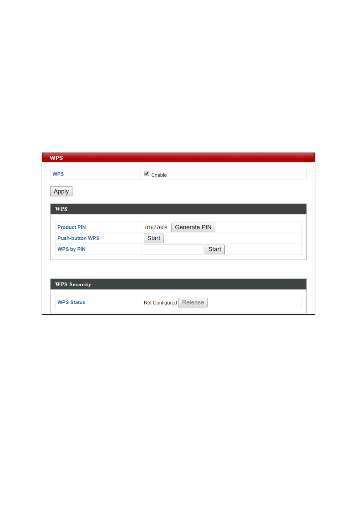
WPS
Check/uncheck this box to enable/disable WPS functionality.
Press “Apply” to apply the settings.
WPS must be disabled when using MAC-RADIUS
authentication (see IV-3-4 RADIUS).
IV-3-3 WPS
Wi-Fi Protected Setup is a simple way to establish connections between WPS
compatible devices. WPS can be activated on compatible devices by pushing a
WPS button on the compatible device or from within the compatible device’s
firmware / configuration interface (known as PBC or “Push Button
Configuration”). When WPS is activated in the correct manner and at the
correct time for two compatible devices, they will automatically connect. “PIN
code WPS” is a variation of PBC which includes the additional use of a PIN
code between the two devices for verification.
Please refer to manufacturer’s instructions for your other WPS device.
Press “Apply” to apply the configuration.
73
Page 74

WPS
Product PIN
Displays the WPS PIN code of the device, used for PIN code
WPS. You will be required to enter this PIN code into another
WPS device for PIN code WPS. Click “Generate PIN” to
generate a new WPS PIN code.
Push-Button
WPS
Click “Start” to activate WPS on the device for approximately
2 minutes.
WPS by PIN
Enter the PIN code of another WPS device and click “Start” to
attempt to establish a WPS connection. WPS function will last
for approximately 2 minutes.
WPS Security
WPS Status
WPS security status is displayed here. Click “Release” to clear
the existing status.
74
Page 75

IV-3-4 RADIUS
The RADIUS menu allows you to configure the device’s external RADIUS server
settings.
A RADIUS server provides user-based authentication to improve security and
offer wireless client control – users can be authenticated before gaining
access to a network.
The device can utilize a primary and a secondary (backup) external RADIUS
server for each of its wireless frequencies (2.4GHz & 5GHz).
To use RADIUS servers, go to “Wireless Settings” “Security” and select
“MAC RADIUS Authentication” “Additional Authentication” and select
“MAC RADIUS Authentication” (see IV-3-1-3 or IV-3-2-3).
75
Page 76

IV-3-4-1 RADIUS Settings
Configure the RADIUS server settings for 2.4GHz and 5GHz. Each frequency
can use an internal or external RADIUS server.
76
Page 77

RADIUS Type
Select “Internal” to use the access point’s built-in RADIUS
server or “external” to use an external RADIUS server.
RADIUS Server
Enter the RADIUS server host IP address.
Authentication
Port
Set the UDP port used in the authentication protocol of the
RADIUS server. Value must be between 1 – 65535.
Shared Secret
Enter a shared secret/password between 1 – 99 characters in
length. This should match the “MAC-RADIUS” password used
in IV-3-1-3 or IV-3-2-3.
Session
Timeout
Set a duration of session timeout in seconds between 0 –
86400.
Accounting
Enable or disable RADIUS accounting.
Accounting
Port
When accounting is enabled (above), set the UDP port used
in the accounting protocol of the RADIUS server. Value must
be between 1 – 65535.
Press “Apply” to apply the configuration, or “Cancel” to forfeit the changes.
77
Page 78

Internal Server
Check/uncheck to enable/disable the access point’s internal
RADIUS server.
EAP Internal
Authentication
Select EAP internal authentication type from the drop down
menu.
EAP Certificate
File Format
Displays the EAP certificate file format: PCK#12(*.pfx/*.p12)
EAP Certificate
File
Click “Upload” to open a new window and select the location
of an EAP certificate file to use. If no certificate file is
uploaded, the internal RADIUS server will use a self-made
certificate.
Shared Secret
Enter a shared secret/password for use between the internal
RADIUS server and RADIUS client. The shared secret should
be 1 – 99 characters in length. This should match the
“MAC-RADIUS” password used in IV-3-1-3 or IV-3-2-3.
IV-3-4-2 Internal Server
The access point features a built-in RADIUS server which can be configured as
shown below used when “Internal” is selected for “RADIUS Type” in the
“Wireless Settings” “RADIUS” “RADIUS Settings” menu.
To use RADIUS servers, go to “Wireless Settings” “Security” and select
“MAC RADIUS Authentication” “Additional Authentication” and select
“MAC RADIUS Authentication” (see IV-3-1-3 & IV-3-2-3).
78
Page 79

Session
Timeout
Set a duration of session timeout in seconds between 0 –
86400.
Termination
Action
Select a termination-action attribute:
Reauthentication: sends a RADIUS request to the access
point; or,
Not-Reauthentication: sends a default termination-action
attribute to the access point; or
Not-Send: no termination-action attribute is sent to the
access point.
Press “Apply” to apply the configuration, or “Cancel” to forfeit the changes.
79
Page 80

IV-3-4-3 RADIUS Accounts
The internal RADIUS server can authenticate up to 256 user accounts. The
“RADIUS Accounts” page allows you to configure and manage users.
Enter a username in the box below and click “Add” to add the username.
80
Page 81

User Name
Enter the user names here, separated by commas.
Add
Click “Add” to add the user to the user registration list.
Reset
Clear text from the user name box.
Select
Check the box to select a user.
User Name
Displays the user name.
Password
Displays if specified user name has a password (configured) or
not (not configured).
Customize
Click “Edit” to open a new field to set/edit a password for the
specified user name (below).
Delete
Selected
Delete selected user from the user registration list.
Delete All
Delete all users from the user registration list.
Select “Edit” to edit the username and password of the RADIUS account:
Press “Apply” to apply the configuration, or “Cancel” to forfeit the changes.
81
Page 82

IV-3-5 MAC Filter
MAC filtering is a security feature that can help to prevent unauthorized users
from connecting to your access point.
This function allows you to define a list of network devices permitted to
connect to the access point. Devices are each identified by their unique MAC
address. If a device which is not on the list of permitted MAC addresses
attempts to connect to the access point, it will be denied.
To enable MAC filtering, go to “Wireless Settings” “2.4G
Hz 11bgn” “Security” “Additional Authentication” and select “MAC
Filter” (see IV-3-1-3 or IV-3-2-3).
The MAC address filtering table is displayed below:
82
Page 83

Add MAC
Address
Enter a MAC address of computer or network device manually
e.g. ‘aa-bb-cc-dd-ee-ff’ or enter multiple MAC addresses
separated with commas, e.g.
‘aa-bb-cc-dd-ee-ff,aa-bb-cc-dd-ee-gg’
Add
Click “Add” to add the MAC address to the MAC address
filtering table.
Reset
Clear all fields.
Select
Delete selected or all entries from the table.
MAC Address
The MAC address is listed here.
Delete
Selected
Delete the selected MAC address from the list.
Delete All
Delete all entries from the MAC address filtering table.
Export
Click “Export” to save a copy of the MAC filtering table. A new
window will pop up for you to select a location to save the file.
MAC address entries will be listed in the “MAC Address Filtering Table”. Select
an entry using the “Select” checkbox.
83
Page 84

Background
Low Priority
High throughput, non time sensitive bulk data e.g.
FTP
Best Effort
Medium
Priority
Traditional IP data, medium throughput and delay.
Video
High Priority
Time sensitive video data with minimum time
delay.
Voice
High Priority
Time sensitive data such as VoIP and streaming
media with minimum time delay.
IV-3-6 WMM
Wi-Fi Multimedia (WMM) is a Wi-Fi Alliance interoperability certification
based on the IEEE 802.11e standard, which provides Quality of Service (QoS)
features to IEE 802.11 networks. WMM prioritizes traffic according to four
categories: background, best effort, video and voice.
Configuring WMM consists of adjusting parameters on queues for different
categories of wireless traffic. Traffic is sent to the following queues:
84
Page 85

CWMin
Minimum Contention Window (milliseconds): This value is input
to the initial random backoff wait time algorithm for retry of a
data frame transmission. The backoff wait time will be generated
between 0 and this value. If the frame is not sent, the random
backoff value is doubled until the value reaches the number
defined by CWMax (below). The CWMin value must be lower
than the CWMax value. The contention window scheme helps to
avoid frame collisions and determine priority of frame
transmission. A shorter window has a higher probability
(priority) of transmission.
CWMax
Maximum Contention Window (milliseconds): This value is the
upper limit to random backoff value doubling (see above).
AIFSN
Arbitration Inter-Frame Space (milliseconds): Specifies additional
time between when a channel goes idle and the AP/client sends
data frames. Traffic with a lower AIFSN value has a higher
priority.
TxOP
Transmission Opportunity (milliseconds): The maximum interval
of time an AP/client can transmit. This makes channel access
more efficiently prioritized. A value of 0 means only one frame
per transmission. A greater value means higher priority.
Queues automatically provide minimum transmission delays for video, voice,
multimedia and critical applications. The values can be adjusted further
manually:
Press “Apply” to apply the configuration, or “Cancel” to forfeit the changes.
85
Page 86

IV-3-7 Schedule
The schedule feature allows you to automate the wireless network for the
specified time ranges. Wireless scheduling can save energy and increase the
security of your network.
Check/uncheck the box “Enable” and select “Apply” to enable/disable the
wireless scheduling function.
1. Select “Add” to add a schedule.
2. Settings page will be shown if “Continue” is selected:
Check/uncheck the box of the desired SSID network, day of schedule
and select the Start Time and End Time (using the dropdown menu).
Select “Apply” to apply the settings, or “Cancel” to forfeit the schedule.
86
Page 87

Schedules will be shown in the Schedule List as exemplified below:
3. Select “Add” to add more schedules; or
Check the box of currently available schedule, select “Edit” to edit, or
select “Delete Selected” to delete; or
Select “Delete All” to delete all schedules.
87
Page 88

IV-3-8 Traffic Shaping
Traffic shaping is used to optimize or guarantee performance, improve latency,
or increase usable bandwidth for some kinds of packets by delaying other
kinds.
Check the checkbox to enable traffic shaping, specify the down link and up
link values, and click “Apply” to apply the configuration, or “Cancel” to forfeit
the changes.
88
Page 89

89
Page 90

IV-3-9 Bandsteering
Band steering detects clients capable of 5GHz operation and steers them
there to make the more crowded 2.4 GHz band available for clients only
capable of connecting to 2.4GHz band. This helps improve end user
experience by reducing channel utilization, especially in high density
environments.
If “User Define” is selected, specify the numbers in the fields below:
90
Page 91

Account to Manage This Device
Administrator
Name
Set the access point’s administrator name. This is used to log
in to the browser based configuration interface and must be
between 4-16 alphanumeric characters (case sensitive).
Administrator
Password
Set the access point’s administrator password. This is used to
log in to the browser based configuration interface and must
be between 4-32 alphanumeric characters (case sensitive).
IV-4 Management
(Configurable for AP Mode only)
IV-4-1 Admin
You can change the password used to login to the browser-based
configuration interface here. It is advised to do so for security purposes.
If you change the administrator password, please make a note of the
new password. In the event that you forget this password and are
Reset for how to reset the access point.
unable to login to the browser based configuration interface, see 0
Press “Apply” to apply the configuration.
91
Page 92

Advanced Settings
Product Name
Edit the product name according to your preference
consisting of 1-32 alphanumeric characters. This name is used
for reference purposes.
Management
Protocol
Check/uncheck the boxes to enable/disable specified
management interfaces (see below). When SNMP is enabled,
complete the SNMP fields below.
SNMP Version
Select SNMP version appropriate for your SNMP manager.
SNMP Get
Community
Enter an SNMP Get Community name for verification with the
SNMP manager for SNMP-GET requests.
SNMP Set
Community
Enter an SNMP Set Community name for verification with the
SNMP manager for SNMP-SET requests.
SNMP Trap
Enable or disable SNMP Trap to notify SNMP manager of
network errors.
SNMP Trap
Enter an SNMP Trap Community name for verification with
92
Page 93

Community
the SNMP manager for SNMP-TRAP requests.
SNMP Trap
Manager
Specify the IP address or sever name (2-128 alphanumeric
characters) of the SNMP manager.
HTTP
Internet browser HTTP protocol management interface
TELNET
Client terminal with telnet protocol management interface
SNMP
Simple Network Management Protocol. SNMPv1, v2 & v3 protocol supported.
SNMPv2 can be used with community based authentication. SNMPv3 uses
user-based security model (USM) architecture.
Press “Apply” to apply the configuration.
93
Page 94

Date and Time Settings
Local Time
Set the access point’s date and time manually using the drop
down menus.
Acquire
Current Time
from your PC
Click “Acquire Current Time from Your PC” to enter the
required values automatically according to your computer’s
current time and date.
IV-4-2 Date and Time
Configure the date and time settings of the access point here. The date and
time of the device can be configured manually or can be synchronized with a
time server.
94
Page 95

NTP Time Server
Use NTP
The access point also supports NTP (Network Time Protocol)
for automatic time and date setup.
Server Name
Enter the host name or IP address of the time server if you
wish.
Update
Interval
Specify a frequency (in hours) for the access point to
update/synchronize with the NTP server.
Time Zone
Time Zone
Select the time zone of your country/region. If your
country/region is not listed, please select another
country/region whose time zone is the same as yours.
Press “Apply” to apply the configuration, or “Cancel” to forfeit the changes.
95
Page 96

Syslog Server Settings
Transfer Logs
Check the box to enable the use of a syslog server.
Enter a host name, domain or IP address for the server,
consisting of up to 128 alphanumeric characters.
Syslog E-mail Settings
E-mail Logs
Check the box to enable/disable e-mail logs.
E-mail Subject
Specify the subject line of log emails.
SMTP Server
Address
Specify the SMTP server address used to send log emails.
SMTP Server
Port
Specify the SMTP server port used to send log emails.
Sender E-mail
Specify the sender email address.
Receiver
E-mail
Specify the email to receive log emails.
Authentication
Disable or select authentication type: SSL or TLS. When using
SSL or TLS, enter the username and password.
IV-4-3 Syslog Server
The system log can be sent to a server.
Press “Apply” to apply the configuration, or “Cancel” to forfeit the changes.
96
Page 97

Destination Address
Enter the address of the host.
Execute
Click “Execute” to ping the host.
IV-4-4 Ping Test
The access point includes a built-in ping test function. Ping is a computer
network administration utility used to test whether a particular host is
reachable across an IP network and to measure the round-trip time for sent
messages.
97
Page 98

Duration of
Sound
Set the duration for which the buzzer will sound when the
“Sound Buzzer” button is clicked.
Sound Buzzer
Activate the buzzer sound for a duration specified above.
IV-4-5 I’m Here
The access point features a built-in buzzer which can sound on command
using the “I’m Here” page. This is useful for network administrators and
engineers working in complex network environments to locate the access
point.
The buzzer is loud!
98
Page 99

Power LED
Select on or off.
2.4GHz LED
Select on or off.
5GHz LED
Select on or off.
Diag LED
Select on or off.
IV-5 Advanced
IV-5-1 LED Settings
The access point’s LEDs can be manually enabled or disabled according to
your preference.
99
Page 100

Firmware Location: Auto
Current
Firmware
Version
Displays current firmware version.
Server
Firmware
Version
Displays available firmware version on the server.
Status
Displays availability of firmware.
Check
Click to check available firmware version.
IV-5-2 Update Firmware
The “Firmware” page allows you to update the firmware of the system.
Updated firmware versions often offer increased performance and security, as
well as bug fixes. Download the latest firmware from the Edimax website.
Do not switch off or disconnect the access point during a firmware
upgrade, as this could damage the device.
100
 Loading...