

Page 1

IR-113E
User Manual
02-2012 / v1.0
Page 2

- CONTENTS -
Chapter I Introduction ................................................................................................ 1
1.1 Highlights of your new Network IP Camera .......................................................... 1
1.2 Safety Instructions ............................................................................................... 2
1.3 Packaging Contents ............................................................................................. 3
1.4 Familiar with your new Network IP Camera .......................................................... 3
1.5 Installation of the Network IP Camera .................................................................. 7
Chapter II Using Network IP Camera by Web Interface ................................................. 9
2.1 Locate the IP address of Network IP Camera ............................................................... 9
2.2 Connect to IP Camera’s Web User Interface and Install ActiveX Plugin ....................... 12
2.3 Viewing Live Video ................................................................................................... 14
2.4 Client Settings .......................................................................................................... 18
Chapter III Advanced Configuration ................................................................................ 20
3-1 System ..................................................................................................................... 21
3-2 Security.................................................................................................................... 23
3-3 Network................................................................................................................... 25
3-3-1 “General” Setup Page ................................................................................................ 25
3-3-2 “Advanced” Setup Page ............................................................................................. 28
3-4 IP Filter .................................................................................................................... 31
3-5 Video ....................................................................................................................... 33
3-5-1 Image Setting ............................................................................................................. 33
3-5-2 Video Setting .............................................................................................................. 35
3-5-3 Overlay Setting ........................................................................................................... 37
3-6 Audio ....................................................................................................................... 38
3-7 Motion..................................................................................................................... 39
3-8 PTZ Control (RS-485)................................................................................................. 41
3-9 Event ....................................................................................................................... 43
Page 3

3-9-1 Settings ...................................................................................................................... 44
3-9-2 Media ......................................................................................................................... 46
3-9-3 Event Server ............................................................................................................... 47
3-10 Recording to SD Card .............................................................................................. 50
3-11 Log ......................................................................................................................... 51
3-12 Device Info ............................................................................................................. 51
3-13 Maintenance .......................................................................................................... 52
3-14 Language................................................................................................................ 54
CHAPTER IV: EDIVIEW 64-CHANNEL VIEWER ................................................................... 55
4-1 EdiView Installation ................................................................................................. 55
4-2 EdiView Interface ..................................................................................................... 63
4-3 Configuration ........................................................................................................... 72
4-3-1 Device......................................................................................................................... 73
4-3-2 Recording ................................................................................................................... 76
4-3-3 System ........................................................................................................................ 79
4-3-4 Schedule ..................................................................................................................... 83
4-3-5 Event .......................................................................................................................... 87
4-3-6 Security ...................................................................................................................... 89
4-4 Video Playback ......................................................................................................... 91
4-4-1 Advanced Search ........................................................................................................ 93
4-4-2 Event Search .............................................................................................................. 96
4-4-3Video Playback .......................................................................................................... 100
Chapter V Troubleshooting ....................................................................................... 103
Notice According to GNU General Public License Version 2 ............................................ 103
Page 4

Chapter I Introduction
1.1 Highlights of your new Network IP Camera
Congratulates on purchasing this high-resolution 3Mega pixels network IP
Camera! This IP Camera provides 3Mega pixels high-resolution video
quality, with the advanced megapixel lens, you can view images remotely
in more detail than conventional close-circuit cameras.
Other highlights of this network IP Camera include:
Ultra-high resolution 5Mega pixel CMOS image sensor.
Analog video (BNC) output, works with conventional video devices such
as TV Monitors, analog DVRs, etc.
Digital input / output interface lets you connect peripherals such as
external alarm, sensor, etc.
Audio input / output interface, you can listen to voices in remote place,
and speak to person in remote place.
Built-in SD-card slot for local storage, which can act like a stand-alone
DVR.
Two Way audio.
3GPP Mobile Surveillance Supported.
RS-485 communication supported.
ONVIF Compliant.
The IR-113E (PoE model) Supports IEEE802.3af Power over Ethernet
(PoE) standard.
1
Page 5

1.2 Safety Instructions
Please follow the safety instructions listed below when you’re using this
Network IP Camera, or you would harm this camera and / or yourself! Also,
the warranty will become void if you disobey these safety instructions.
This Network IP Camera is sophisticated electronic device; do not drop
it from high places.
Do not place this IP Camera at hot / humid places, and avoid direct
sunlight.
This IP Camera is not a toy; keep it out from the reach of children.
Do not insert any accessories of this IP Camera into your body.
Make sure lens set is secured when you’re using this IP Camera, lens set
may fall down if it’s not properly secured, and cause damage to human
and itself.
If you want to use this IP Camera at any place that may be spilled by
water or dirt, a secure and water-proof camera housing is required.
Do not pull any cord that is connected to this IP Camera by force.
IP Camera will become hot after long time of use. Refrain from touch IP
Camera with hand, or cover this IP camera with paper or cloth.
Never connect powered cable to IP Camera’s DI/DO contacts.
If the IP Camera falls into water when powered, do not attempt to
retrieve it back by yourself! Find a qualified electric technician for help.
2
Page 6
Item No.
Description
Quantity
1
Network camera
1 2 Power adapter
1
3
CD (with utility software, user manual &
multi-language QIG)
1
4
Quick installation guide
1
5
Sun shield kit
1
6
Bracket
1
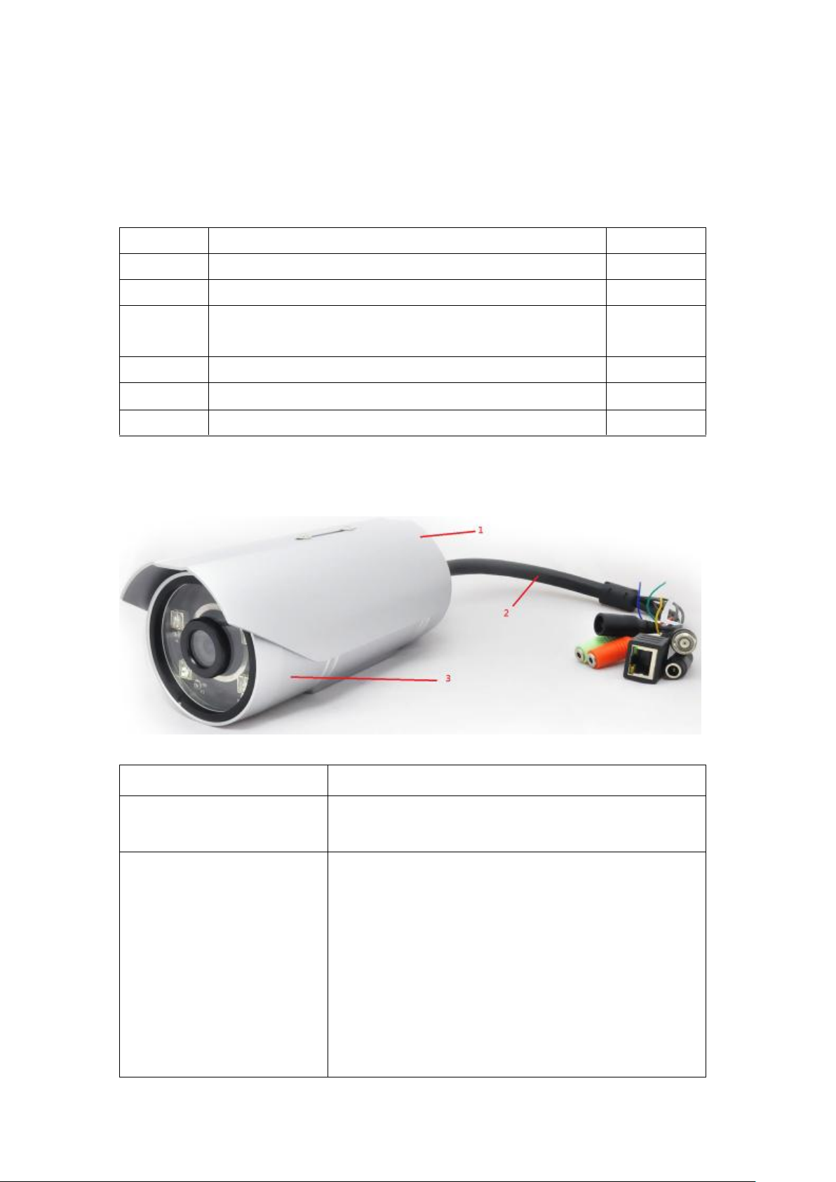
Item
Description
1. Sun shield
Protect camera device body from sun shine
or rain directly
2. I/O cable
Including
-Alarm I/O
-TV output
-Network
-Audio I/O
-RS485 +-
-Reset button
-GND
1.3 Packaging Contents
Please check the contents of your new Network IP Camera when you
unpack the package. If any item is missing, please contact your dealer of
purchase for help.
1.4 Familiar with your new Network IP Camera
3
Page 7
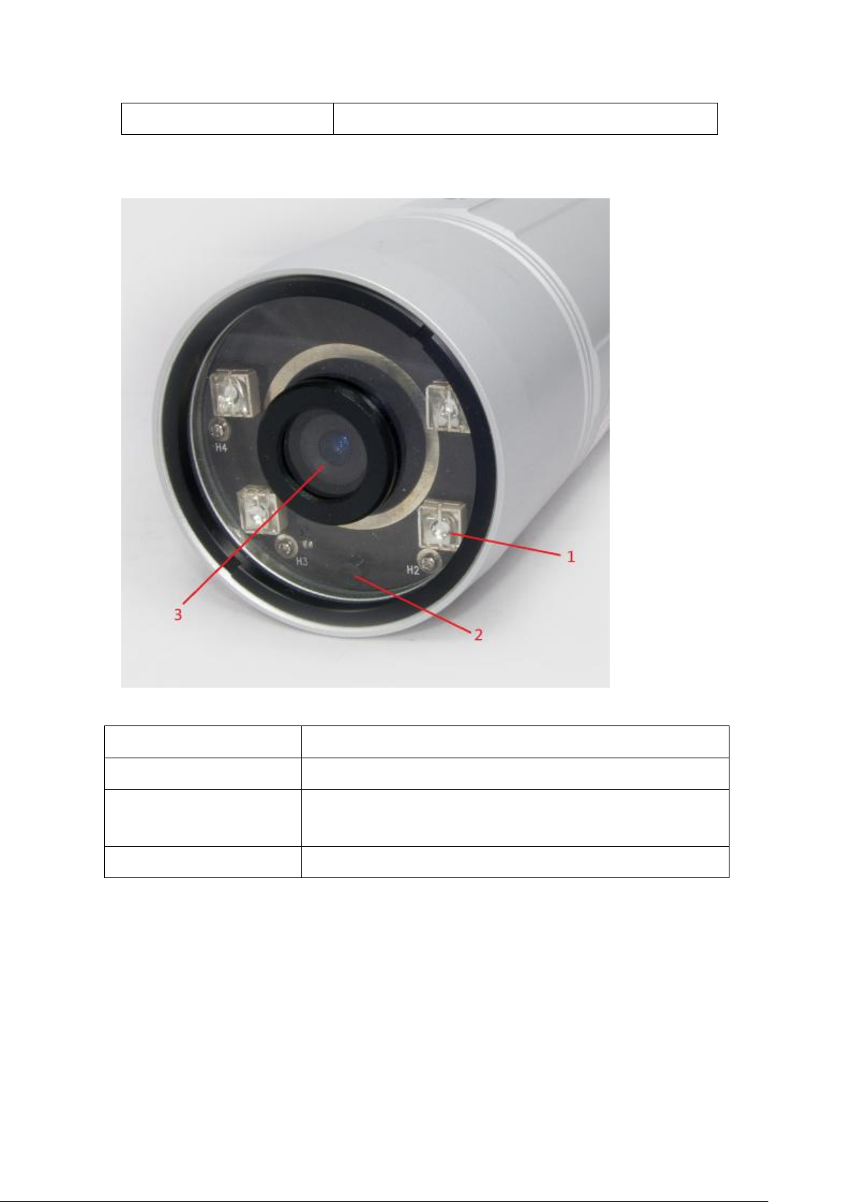
3. IP camera device
IP camera
Item
Description
1. IR-LED
Used for illumination assistance under night mode
2. Day/night sensor
Used for day/night detection and IR-LED ON/OFF
control
3. Lens
Fixed focal length.
[Front site]
4
Page 8
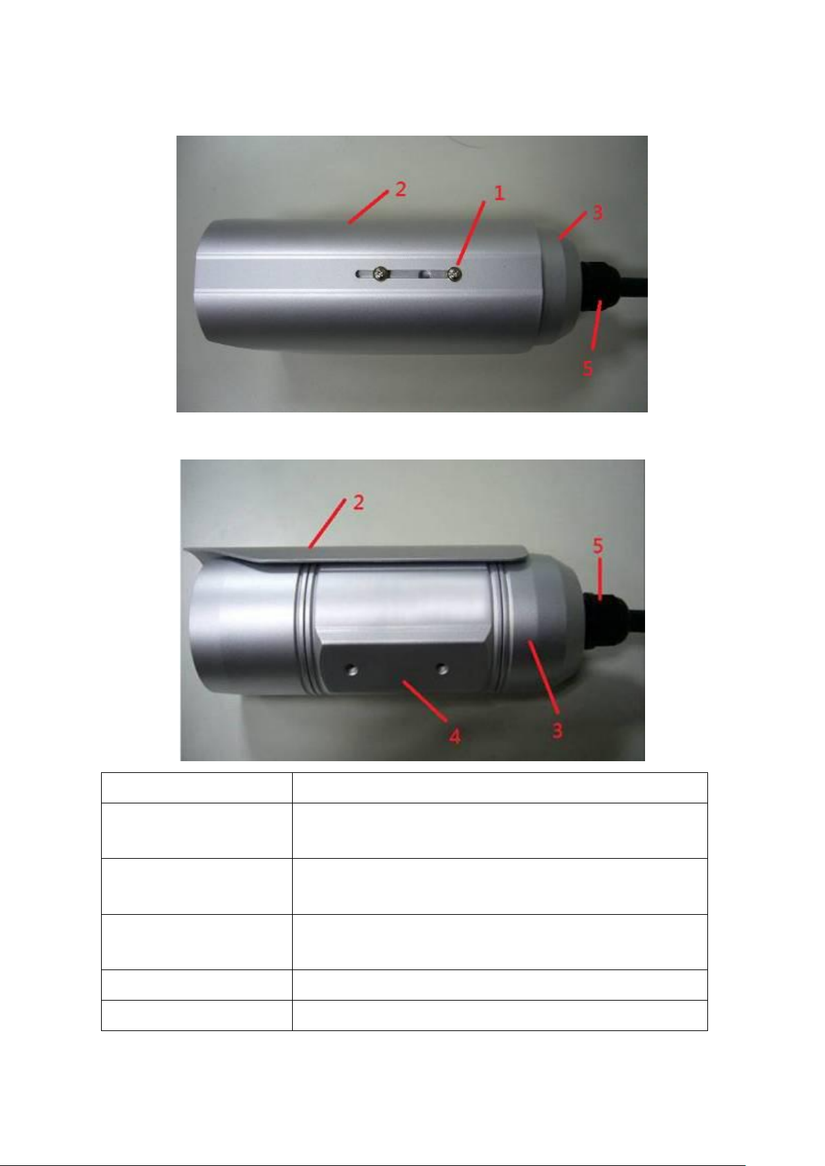
Item
Description
1. Screw
Connects between camera device body & sun
shield.
2. Sun shield
Protect camera device body from sun shine or rain
directly
3. Camera device
body
IP camera metal case
4. Bracket mount
The portion to mount bracket
5. Cable glands
For water proof
[Back]
5
Page 9
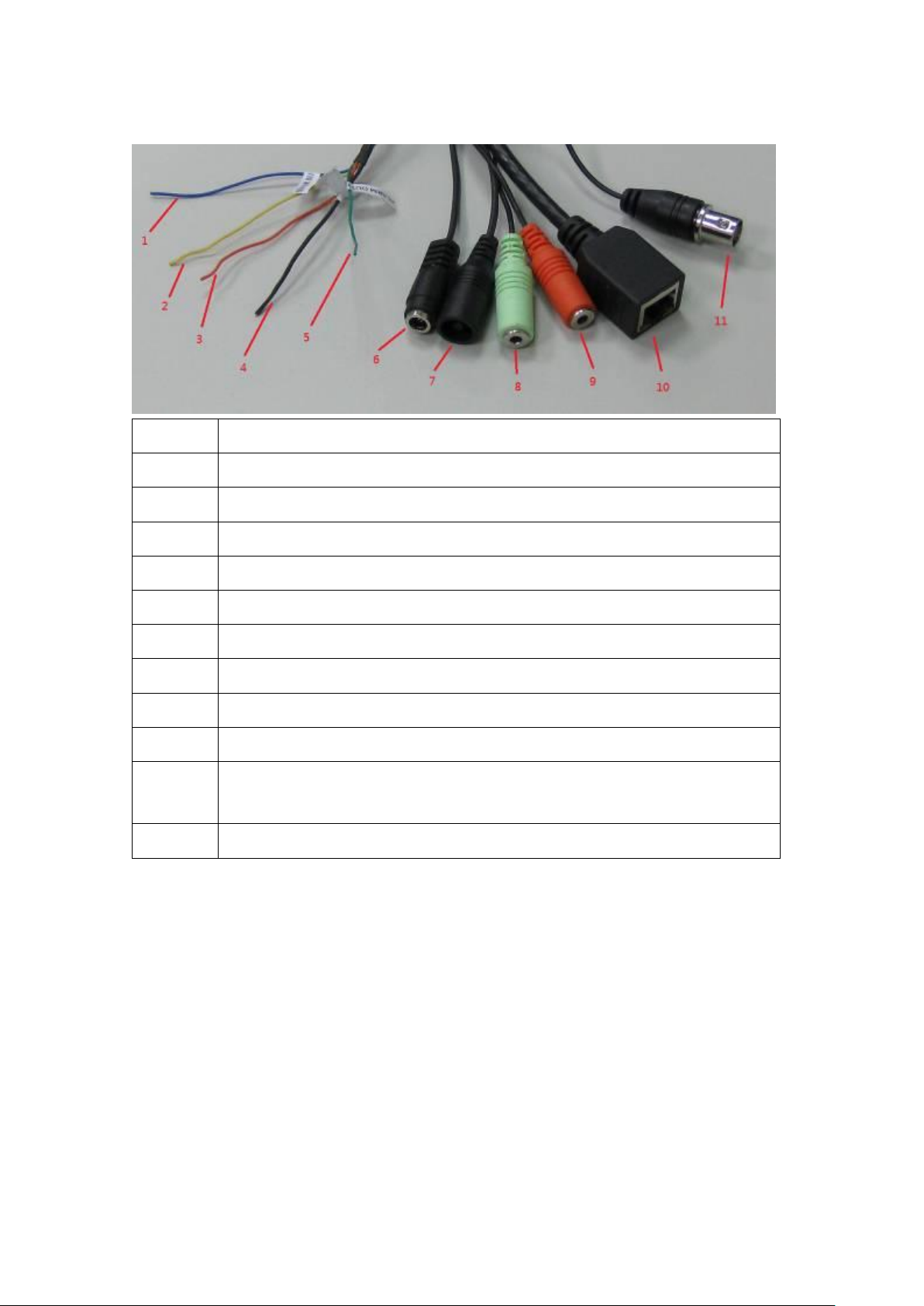
Item
Description
1
Blue, Sensor IN1, for alarm input, DV3.3Volt level allowed.
2
Yellow, RS485 D-
3
Orange, RS485 D+
4
Black, GND
5
Green, Alarm out1, DV3.3Volt level allowed.
6
DC12Volt/2A input
7
Reset Button
8
Audio output
9
Audio input
10
Network, RJ45 connector, two LED index, orange color is
power index, green is network index
11
TV output, BNC connector
[DI/DO PIN ASSIGNMENT]
※Please check the I/O cable attached index before insert or release any
wire.
6
Page 10
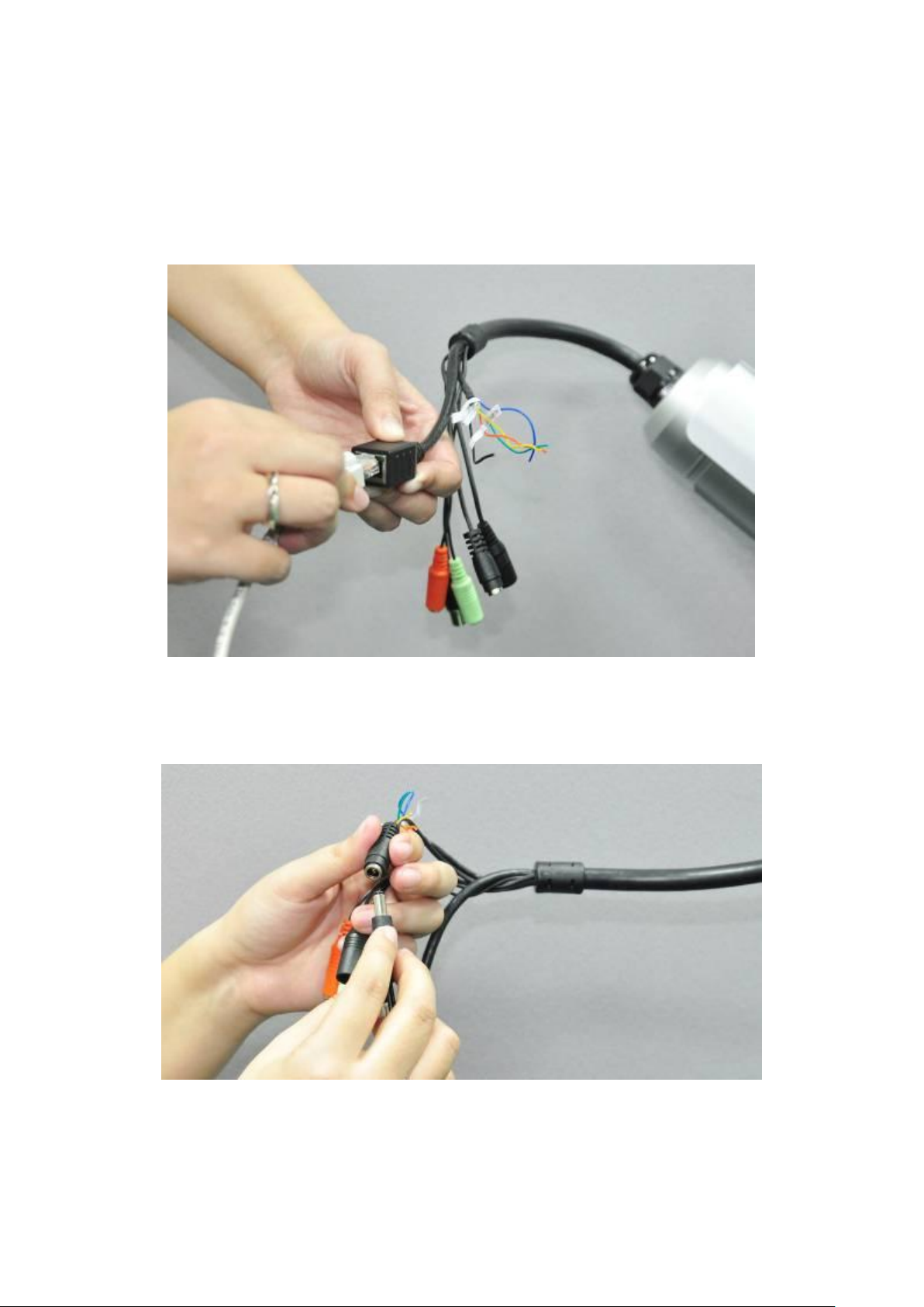
1.5 Installation of the Network IP Camera
Please follow the instructions below to setup your new IP camera.
1. Connect Ethernet cable to LAN port.
2. Plug DC power adapter to power outlet on the wall.
3. Connect DC power cable to IP Camera’s DC power connector.
4. If everything’s ok, you should see the green LED light on LAN port light
up. If not, please recheck every step and try again, or ask your dealer of
purchase for help.
7
Page 11
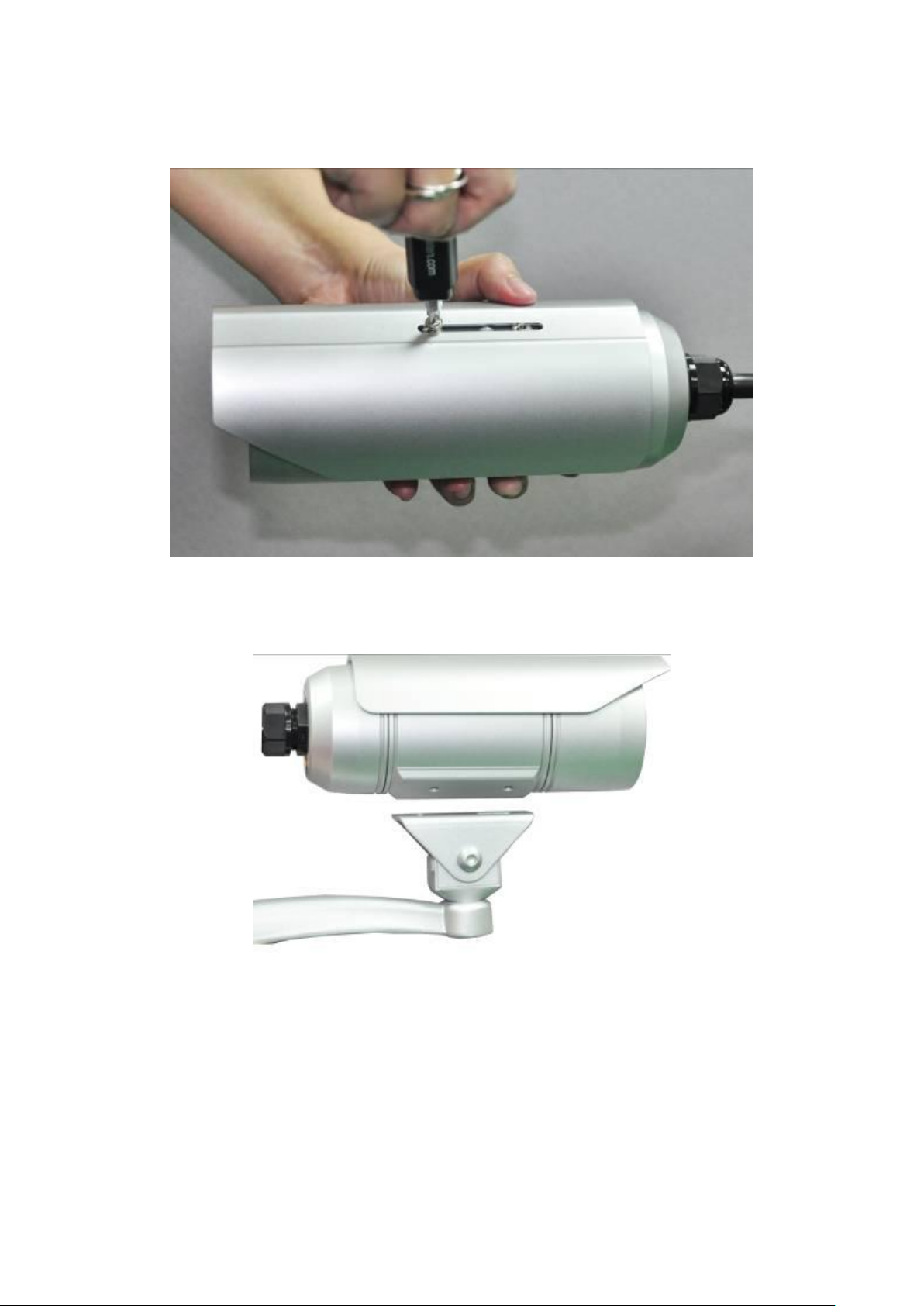
5. Unplug the power then find the screws in the package, use screwdriver
to fix the sun shield on the device’s main body.
6. Secure the wall mounting metal bracket on the wall then secure the
bullet camera on the bracket.
Note: The bracket is an optional extra.
7. Repower on the camera and refer to the following procedures to access
and configure it.
8. If this IP Bullet camera is connected to a PoE switch then the device can
be powered on without use the power adapter.
Note: The IR-113E (PoE model) supports IEEE 802.3af PoE standard. It
can be powered via the Ethernet cable when connected to a PoE switch.
8
Page 12

Chapter II Using Network IP Camera by Web
Interface
2.1 Locate the IP address of Network IP Camera
You can use your new Network IP Camera by its web user interface via web
browser. Currently the viewing system requirement for Network IP camera
is:
■ OS: Microsoft Windows XP/Vista/7
■ Browser: Mozilla Firefox, IE7 (and above for full functionality),
Chrome, Safari or above
■ Cell phone: 3GPP player
■ Quick Time 6.5 or above
By default, the network camera automatically obtains an IP address from
the DHCP server on your local network. Check your DHCP server’s IP
address lease table to find the network camera’s IP address, or use the
EdiView Finder utility included in the CD.
1. Insert the CD into your CD-ROM drive. When the wizard appears, click
“Setup Utility” to install the “EdiView Finder” software.
9
Page 13
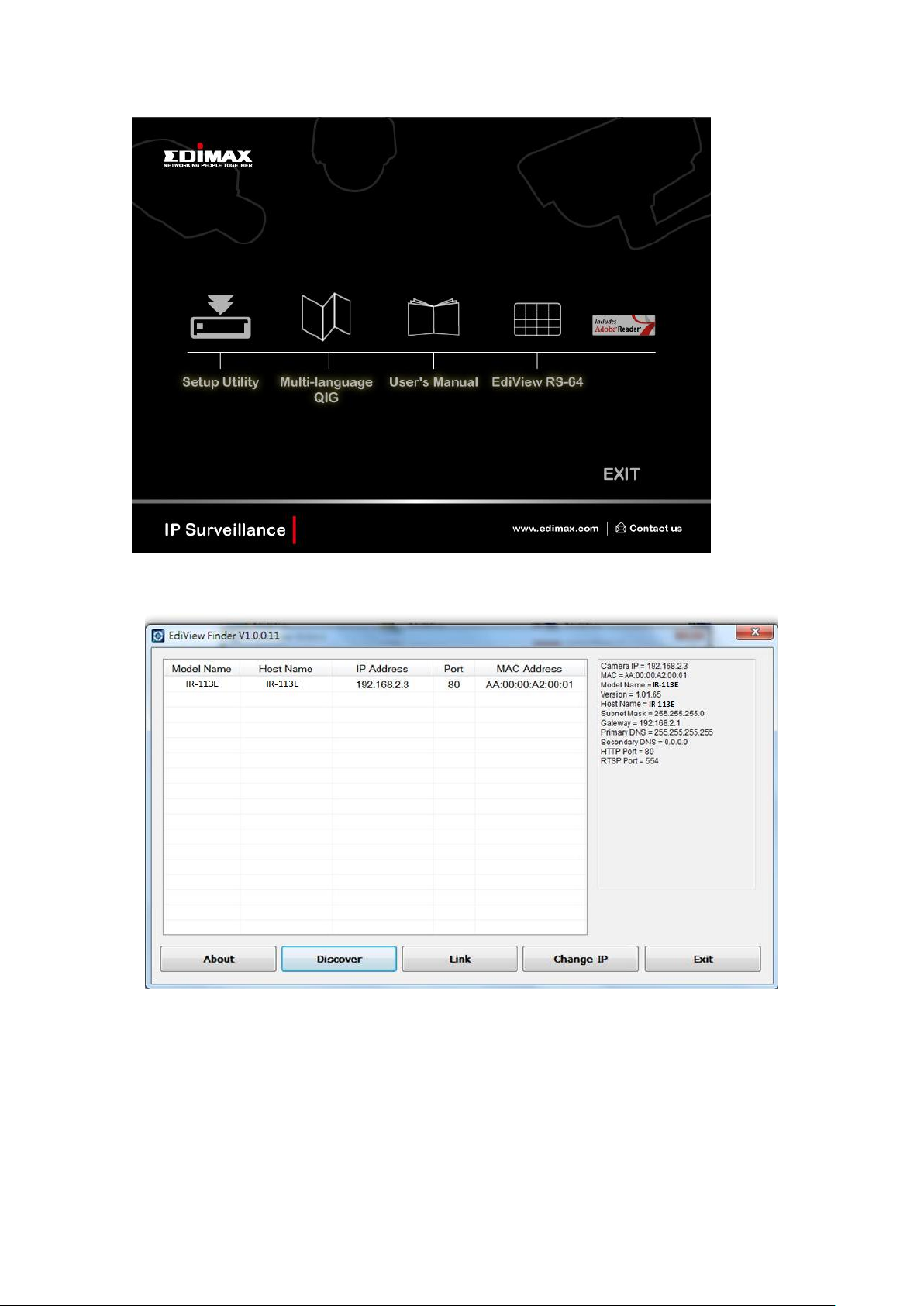
2. After the installation is complete, double-click the “EdiView_Finder”
icon to execute the application.
3. Press ‘Discover’ button to search for all IP Cameras on your local
network (make sure all IP Cameras are powered on and connect to local
network first). When you find any IP Camera, you can double click on it
or click ‘Link’ button to connect to it by your web browser.
If you need to change a certain IP Camera’s IP address, you can also click
on the IP Camera you wish to change IP address, then click ‘Change IP’
10
Page 14

Please note:
If you have several network connections, such as “Wireless
Function”, please disable the “Wireless Functions” or/and
other network connections that is not connected to IP camera,
or IPFinder may fail to search IP camera!
button to change select IP Camera’s IP address setting.
If you no longer need to use this utility, click ‘Exit’ button to close it.
11
Page 15
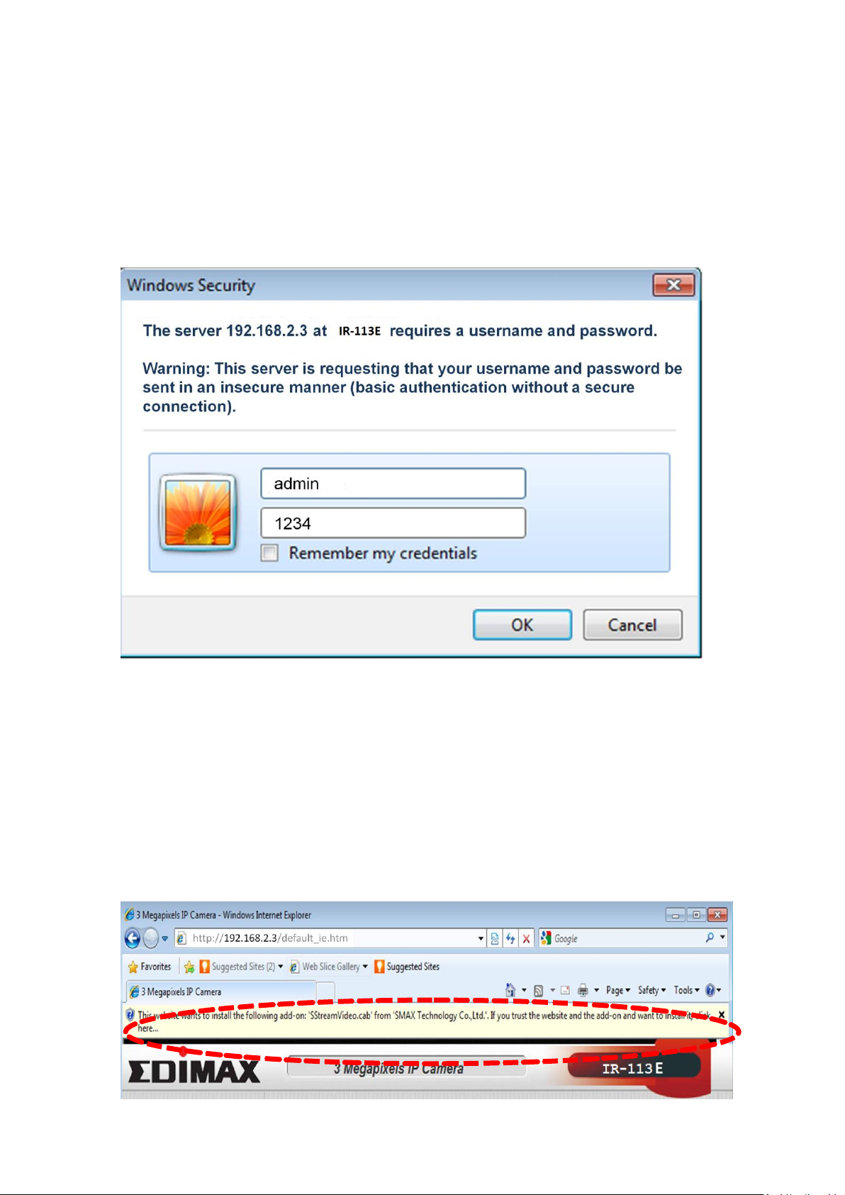
2.2 Connect to IP Camera’s Web User Interface and Install
ActiveX Plugin
When you know the IP address of IP Camera, you can connect to it by
Internet Explorer web browser by entering its IP address in address bar.
The use login screen will appear when you get connected:
IP Camera’s administrator username is ‘admin’ (lower case) and password
is ‘1234’ by default. Click ‘OK’ button or press ‘ENTER’ key on your
keyboard when you finish entering username and password.
When you connect to IP Camera for the first time, you’ll see the following
message. This message prompts you that you need to install ActiveX plugin
before you can see the video from IP Camera.
For IE 8 and earlier version:
12
Page 16
Right click the indication bar and click:
‘‘Install This Add-on for All Users on This Computer…’ to install ActiveX
plugin.
For IE 9:
Click ‘Install’ button located at the bottom of IE to install ActiveX plugin.
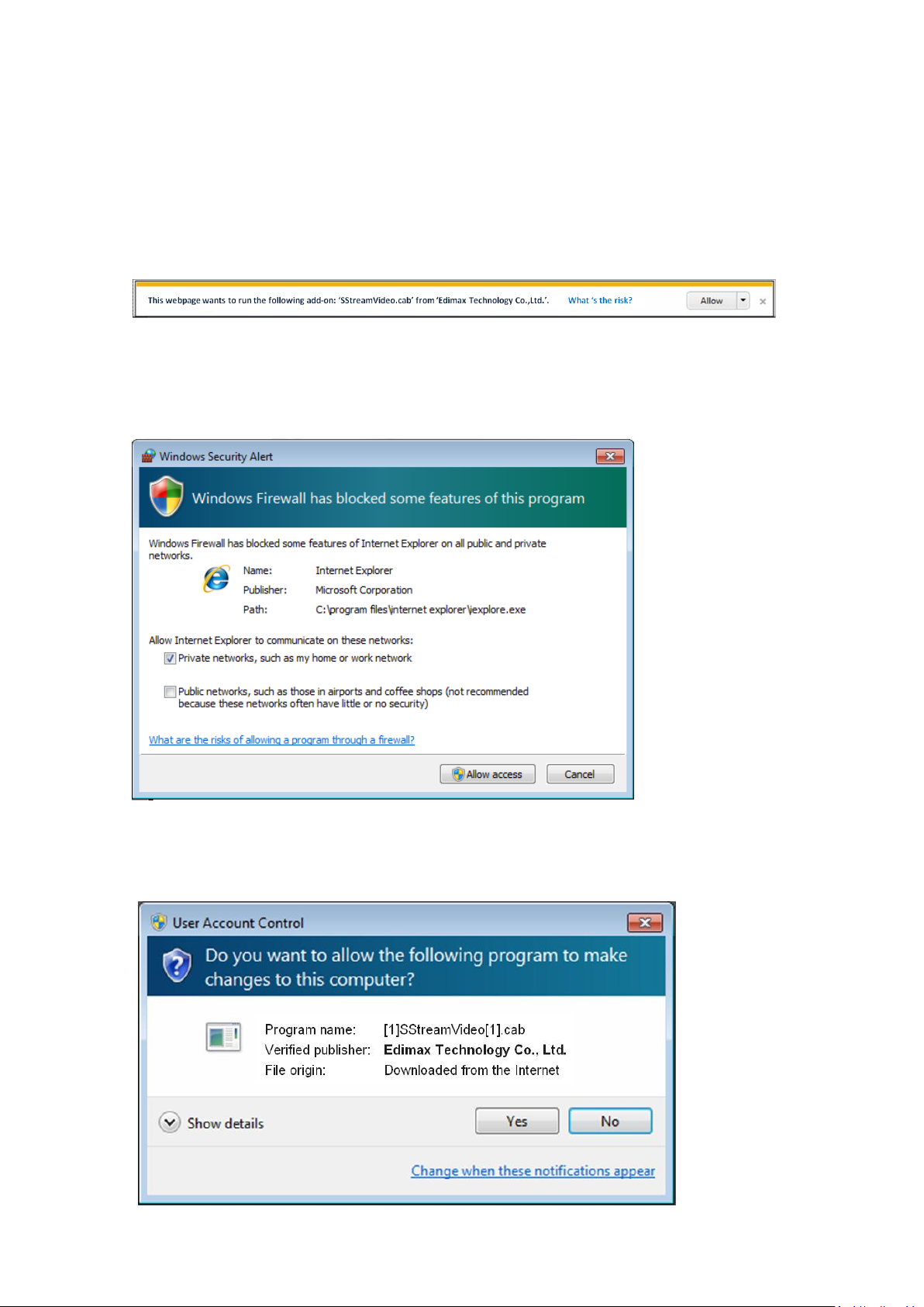
If you’re prompted that:
‘Windows Firewall has blocked some features of this program’
Click ‘Allow access’, or IP Camera will not be able to function properly.
When you’re installing Internet Explorer plugin, you may also be prompted
that if you want to allow changes to be made to your computer:
13
Page 17
NOTE:
If this is the first time you use this IP Camera, you can refer to
chapter 2.4 for instructions on Setup Wizard, which will guide
you to complete the software setup of your new IP Camera.
Click ‘Yes’ to allow changes.
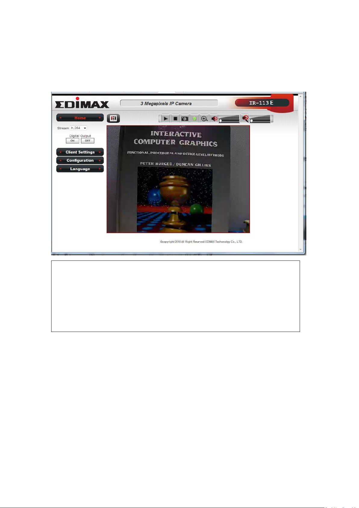
After ActiveX plugin is installed, you should be able to see the video stream
from camera.
2.3 Viewing Live Video
After ActiveX control is installed, you can view IP camera’s video by web
browser. Just connect to IP camera by web browser and login, then you
can see live video from IP camera:
14
Page 18
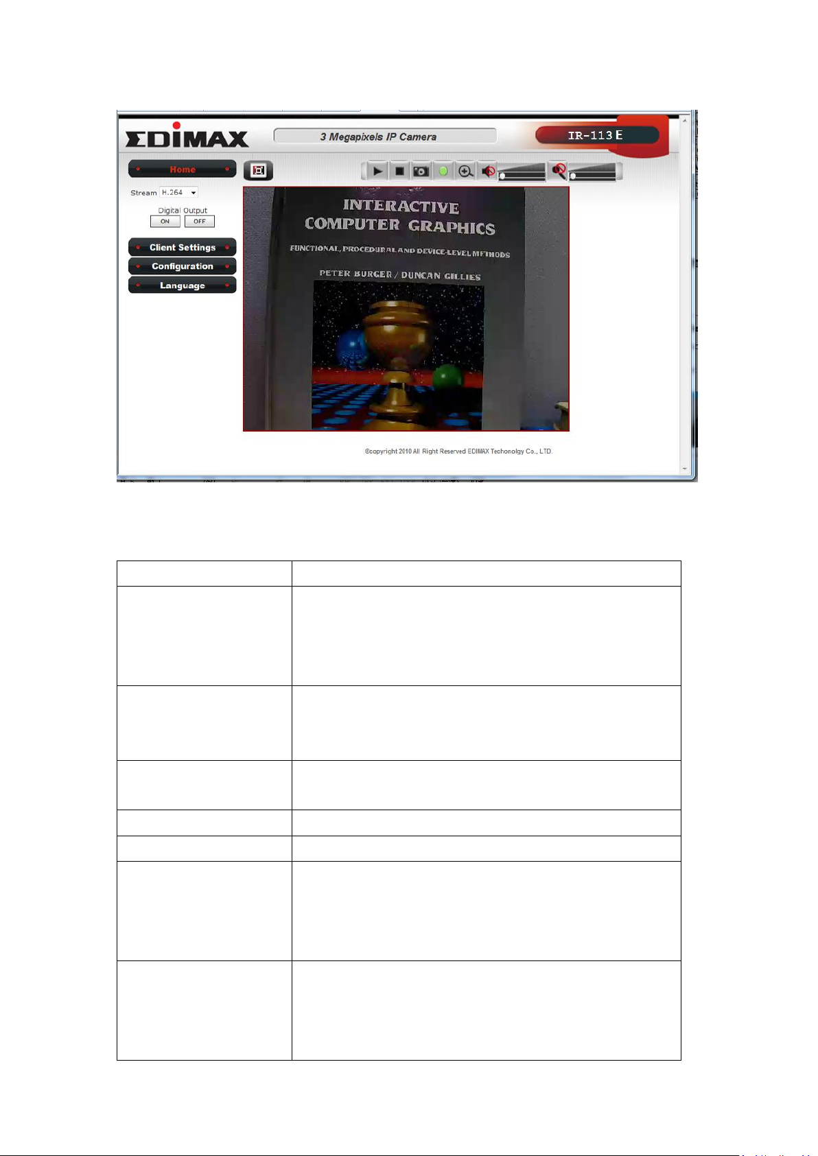
Item
Description
‘Home’ button
This button is visible in all setup pages of IP
camera, and you can go back to live video view
by clicking this button when you’re in other
page.
Stream
Select video stream type: H.264 or MJPEG.
H.264 required less network bandwidth and
this will help when network connection is slow.
Digital Output
(ON / OFF)
Switch digital output interface on or off.
Client Settings
Open ‘Client Setting’ menu.
Configuration
Open ‘Configuration’ menu.
Language
Open language menu, you can switch web
interface to other language.
Available languages: English, Simplified Chinese,
Traditional Chinese
Original size /
Fit screen
Switches live image view between original size
(full size: 3M pixels) and fit screen (smaller
size).
If you want to see video in detail, switch to
There are various controls on web page, here are descriptions of every
control item:
15
Page 19
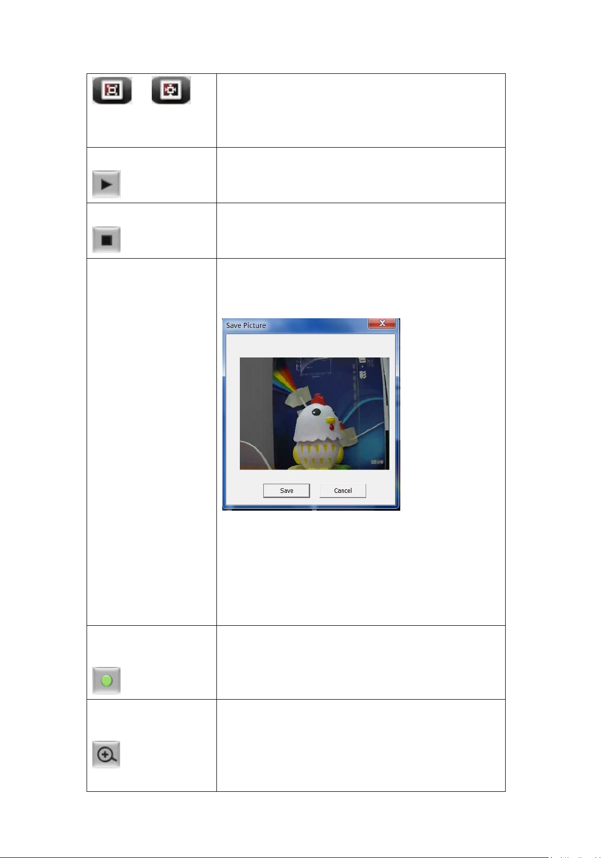
/
original size. If your computer monitor’s
resolution is not enough and you want to see
full image view, switch to fit screen and image
size will adjust automatically.
‘Connect’ button
Start live video view.
‘Disconnect’ button
Stop live video view.
‘Snapshot’ button
Take a snapshot or camera video and save
image file on your computer. When you click
this button, a new window will appear:
Click ‘Save’ button when you see the image you
wish to save, and you’ll be prompted to indicate
the folder on your computer to save image file.
If you changed your mind and don’t want to
save image file, click ‘Cancel’.
‘Start Video Record’
button
Click this button to record video and save video
file on your computer. You’ll be prompted to
indicate the folder on your computer to save
video file.
‘Enable Digital
Zoom’ button
This function will enlarge video view digitally
from 1X to 10X, so you can see objects in video
in detail.
Please note: that digital zoom uses computer
16
Page 20
algorithm to enlarge the video and some details
may lost. If you need to focus on detail of
specific objects in video view, please use optical
zoom ring on lens set of IP camera.
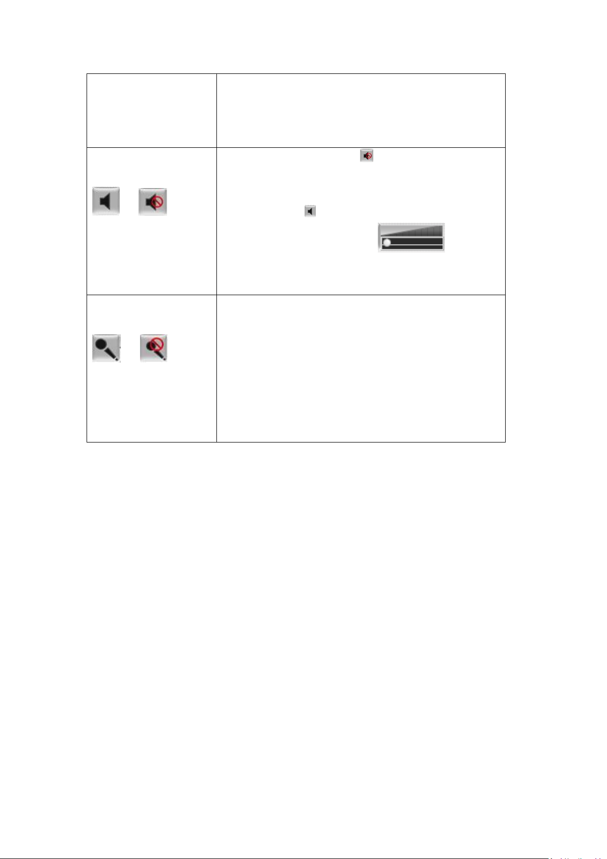
Enable / Disable
mute button
/
When mute is enabled ( ), you will not hear
the voice from IP camera; If you want to hear
voice from IP camera, click this button to
disable mute ( ).
You can drag the slide bar ( ) beside
enable/disable mute button to adjust audio
playback volume.
Start / Stop talk
Button
/
Start or stop playing your voice through IP
camera’s audio output. When talk is stopped,
people at IP camera will not hear you.
Please note: you need a microphone connected
to your computer, and computer’s mixer setting
must enable microphone recording, or nothing
will be outputted by IP camera.
17
Page 21
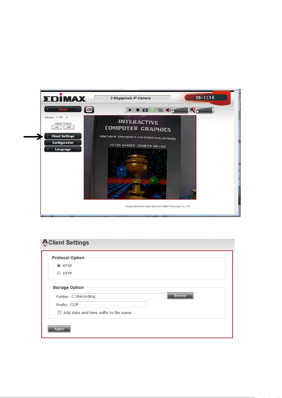
2.4 Client Settings
In ‘Client Settings’ menu, you configure basic IP camera settings like data
transfer protocol and data storage folder.
To access ‘Client Settings’ menu, click ‘Client Settings’ button on the left.
The following screen will appear:
18
Page 22

Item
Description
RTSP
Select this option to use RTSP (Real-Time
Streaming Protocol) to transfer video data.
HTTP
Select this option to use HTTP (Hyper-Text
Transfer Protocol) to transfer video data.
If you don’t know which one you should use,
select ‘RTSP’.
Folder
Select a folder on your computer to save
recorded video. Click ‘Browse’ button and
you’ll be prompted to select a folder.
Prefix
When saving video files, the characters you
typed in ‘Prefix’ field will be used as leading
characters of video file’s name.
For example, the default setting of ‘Prefix’ is
‘CLIP’, and video file’s named will be
‘CLIPxxxx’, where xxxx is a 4-digit serial
number.
Add date and time
suffix to file name
Check this box to add data and time to the
ending part of video file’s filename, so you can
see the date and time the video file is created
directly from its filename.
Here are the descriptions of every setup item:
When you finish with above settings, click ‘Apply’ button to save changes.
19
Page 23
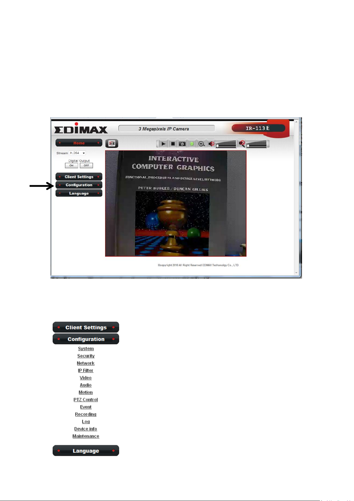
Chapter III Advanced Configuration
If you wish to configure IP camera’s settings, you can access IP camera’s
‘Configuration’ menu, which provides various kinds of system setting.
To access configuration menu, click ‘Configuration’ button on the left.
The ‘Configuration’ submenu will appear, please pick a setup item you
wish to configure.
20
Page 24
Item
Description
Host Name
Input the IP camera’s hostname here, it can be
any meaningful words or characters that will
help you to identify this IP camera. You can use
IP camera’s installation location as host name,
and this will help you to identify IP camera when
you have many IP cameras installed.
Indicator LED
The LED lights located at the back of IP camera is
switched on by default. But, if you don’t want
other people to know the status of this IP
camera (so they will know this IP camera is
operating etc.), you can select ‘Off’ and LED
lights will be switched off.
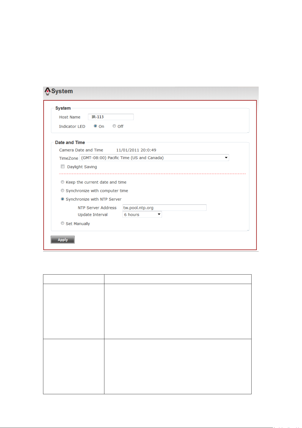
3-1 System
In this menu, you can configure basic IP camera settings like hostname and
time.
Here are the descriptions of every setup item:
21
Page 25

Timezone
Select the time zone of residence from
dropdown menu to keep correct date and time.
Daylight Saving
If the area you live uses daylight saving, check
this box; otherwise do not check this box to keep
time correct.
Keep the current
date and time
Select this option and date / time setting will not
be changed when you click ‘Apply’ in the page.
You can check ‘Camera Date and Time’ item in
this page to know IP camera’s current date and
time setting.
Synchronize with
computer time
Select this item and IP camera will use your
computer’s time as its time.
Synchronize with
NTP Server
Select this item and IP camera will keep its date
and time setting synchronized with specified
time server (NTP server). Please input NTP
server’s IP address or host name in ‘NTP Server
Address’ field, and select time update interval
from ‘Update Interval’ dropdown menu.
Please note that if this IP camera can’t access
Internet, you must have a time server on local
area network, or set the time manually.
Set Manually
Set IP camera’s date and time manually. Please
set current date and time by ‘Date’ and ‘Time’
dropdown menu.
When you finish with above settings, click ‘Apply’ button to save changes.
22
Page 26
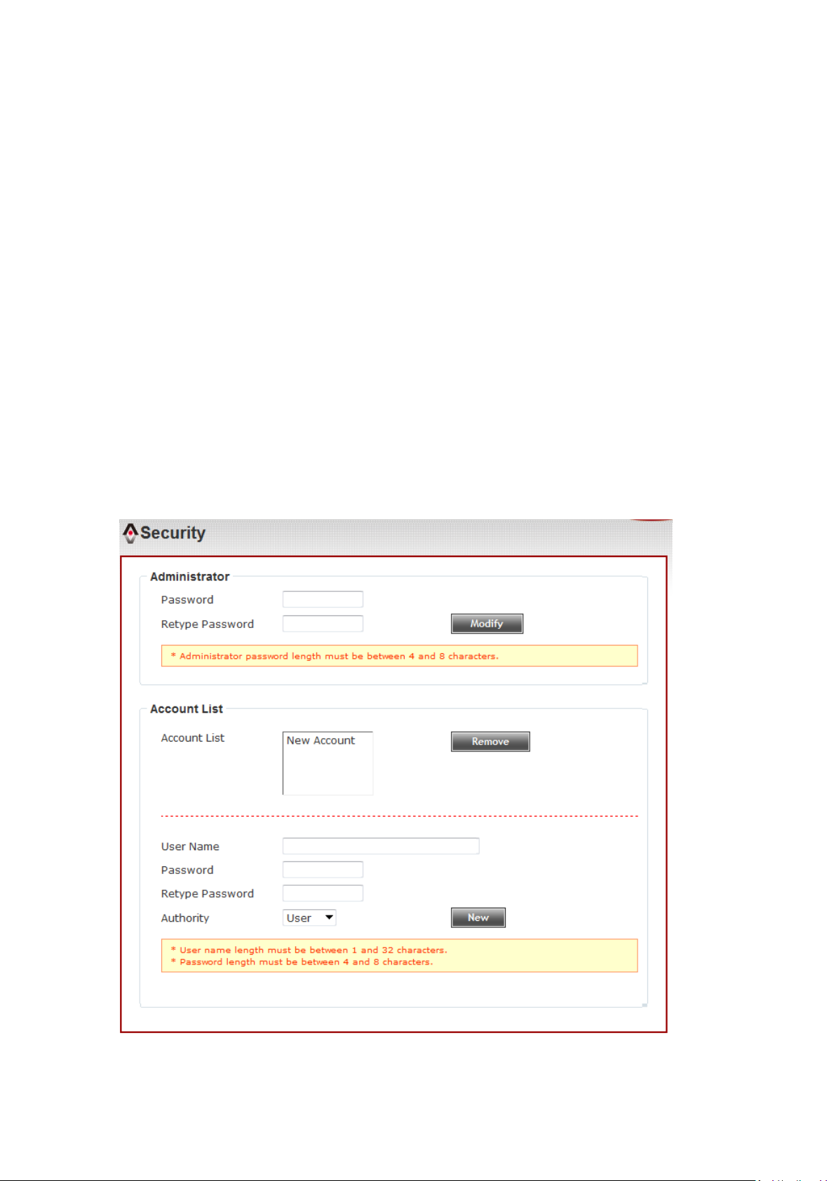
3-2 Security
In this menu, you can configure IP camera’s login account.
There are three kinds of account:
- Administrator (Can view IP camera’s video and make changes of camera
setting)
- User (Can view IP camera’s video and see settings, but can’t make any
change)
- Guest (Can view IP camera’s video only)
There can be multiple users, but only one administrator is allowed, and
you can’t change administrator’s user name (it will always be
‘administrator’).
23
Page 27

Item
Description
Password / Retype
Password
(Administrator)
Input administrator’s new password in both
‘Password’ and ‘Retype Password’ field, and
click ‘Modify’ button to change administrator’s
password.
Please note: Don’t forget administrator’s
password! Or you’ll need to reset IP camera’s all
settings to get administrator’s password
recovered.
Account List
Here lists all users existed in IP camera. If you
want to remove one user, click it in the list, and
then click ‘Remove’ button.
If no user is existed, ‘New Account’ message will
be shown here.
User Name
Input new user’s username here. User name
must be greater than 1 character and less than
32 characters.
Password / Retype
Password
Input this user’s password in both ‘Password’
and ‘Retype Password’ field.
Authority
To define this user’s access privilege, select
‘User’ or ‘Guest’ in dropdown menu.
When you finish inputting new user’s
information, click ‘New’ button to create a new
user.
Here are the descriptions of every setup item:
24
Page 28
3-3 Network
You can configure the network camera’s general and advanced network
settings here.
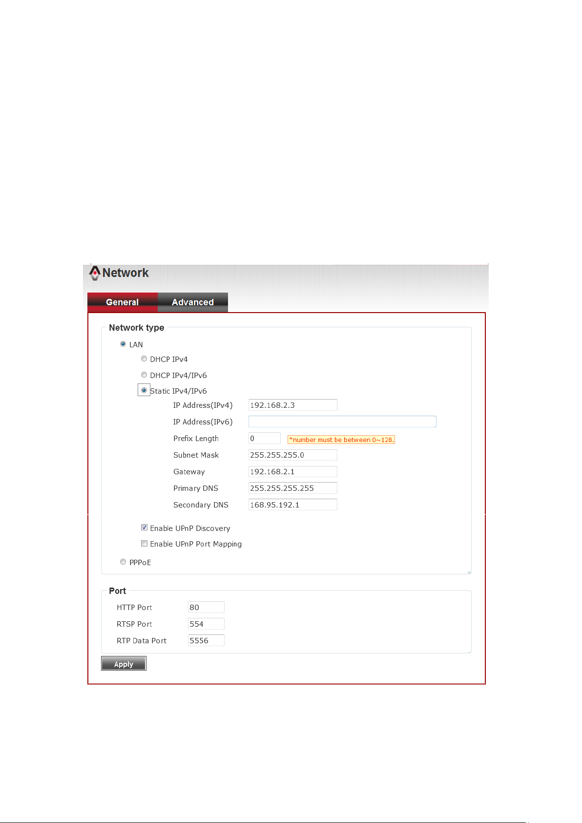
3-3-1 “General” Setup Page
Set up IP address for this IP camera. This IP camera supports both IPv4 and
IPv6 IP address.
25
Page 29

Item
Description
LAN
Select this option to assign an IP address to LAN port (or
obtain an address from DHCP server automatically).
Available options are:
DHCP IPv4: Obtain an IPv4 IP address from DHCP server on
LAN automatically.
DHCP IPv4 / IPv6: Obtain both IPv4 and IPv6 address from
DHCP server on LAN automatically.
Static IPv4 / IPv6: Assign an IPv4 / IPv6 address to IP
camera manually. If you don’t have a DHCP server on your
local area network, you must use this option to specify an
IP address.
IP Address(IPv4): Input IPv4 IP address*
IP Address(IPv6): Input IPv6 IP address*
Prefix Length: Input IPv6 IP address’ prefix length
(0-128)
Subnet Mask: Input subnet mask
Gateway: Input gateway address
Primary DNS: Input DNS server’s IP address
Secondary DNS: Input backup DNS server’s IP address,
you can leave this field blank.
* You can leave this field blank, if you only wish to use
IPv4 or IPv6 IP address.
Enable UPnP Discovery: Check this b ox to enable other
devices on network to discover the presence of this IP
camera by UPnP. It’s recommended to enable this
function.
Enable UPnP Port Mapping: When UPnP is enabled, check
this box to enable UPnP’s port mapping.
Here are the descriptions of every setup item:
26
Page 30

PPPoE
Select this option to use PPPoE to connect to network. You
have to input PPPoE username and password assigned by
network operator to get connected.
HTTP Port
Input IP camera’s web connection port number here.
When this port number is changed, you need to change
web browser’s port number you used to connect to IP
camera.
For example, IP camera’s IP address is 192.168.2.3, and if
you changed HTTP port number to 82, please input
‘http://192.168.2.3:82’ in web browser’s address bar to
access IP camera’s web configuration interface.
RTSP Port
Input RTSP port number. When this port number changes,
you must change corresponding settings in external
network devices (NVR or CMS software) so they can
receive this IP camera’s video.
RTP Data Port
Input RTP data port number here.
When you finish with above settings, click ‘Apply’ button to save changes.
27
Page 31

3-3-2 “Advanced” Setup Page
You can setup advanced network settings in this page. This page is
intended for advanced settings only, and this IP camera will work fine even
you don’t make any changes to this page.
28
Page 32

Item
Description
Multicast
Enable video multicast:
Multicast Group Address: Input multicast group
address here, must be an address between 232.0.0.0 to
232.255.255.255.
Multicast video port: Input port number for video multicast here.
Multicast RCTP video port: Input port number for RCTP video
here.
Multicast audio port: Input port number for audio here.
Multicast RCTP audio port: Input port number for RCTP audio
here.
Multicast TTL: Input TTL value for multicast here.
Bonjour
If you’re using MacOS and you have Bonjour installed, you can use
it to discover this IP camera.
QoS
Enable QoS to improve the data transfer priority of this IP camera
(Your local area network must support QoS).
You can select Video / Audio’s QoS DSCP value (0 to 63), or both
video and audio.
Here are the descriptions of every setup item:
29
Page 33

DDNS
Enable DDNS support if your ISP assigns dynamic IP address to
you. You must register a dynamic IP service first. Currently this IP
camera supports Dyndns and TZO dynamic IP service.
Provider: Select dynamic IP service provider.
Host Name: Input the host name you obtained from dynamic IP
service provider.
User name: Input user name used to login dynamic IP service
provider.
Password: Input the password used to login dynamic IP service
provider.
HTTPS
Check ‘Enable HTTPS’ box to enable HTTPS channel to encrypt
transferred data. You can also define HTTPS port number in
‘HTTPS Port’ field if you don’t want to use default value ‘443’.
When you finish, click ‘Apply’ to save changes.
30
Page 34

3-4 IP Filter
When this IP camera is directly connected to Internet and not protected by
firewall, this function acts like a mini built-in firewall to protect the safety
of this IP camera and avoid attacks from hackers.
31
Page 35

Item
Description
Enable Filter
Check this box to enable IP address filter, uncheck
this Box to disable this function.
Accepted IP list
Here lists all IP address that can build connections
to this IP camera. If you want to remove a set of IP
address from the list, click on the IP address and
click ‘Remove’ button.
IP Address
(Accepted IP list)
Input the starting and ending IP address of IP
address you wish to accept connections here. IP
camera will only accept connections established
from these IP address.
If you want to specify one IP address only, input the
same IP address in both field.
Click ‘New’ button to add IP address into accepted
IP list.
Deny IP list
Here lists all IP address that cannot build
connections to this IP camera. If you want to
remove a set of IP address from the list, click on the
IP address and click ‘Remove’ button.
IP Address
(Accepted IP list)
Input the starting and ending IP address of IP
address you wish to deny connections here. IP
camera will deny connections established from
these IP address.
If you want to specify one IP address only, input the
same IP address in both field.
Click ‘New’ button to add IP address into deny
IP list.
Here are the descriptions of every setup item:
When you finish with above settings, click ‘Apply’ button to save changes.
32
Page 36

3-5 Video
You can adjust the image of the IP camera in this menu.
There are 3 sub-menus in this menu: Image Setting, Video Setting, and
Overlay, which can be accessed by tabs on the top:
3-5-1 Image Setting
You can adjust the image parameters in this page.
33
Page 37

Item
Description
Brightness /
Contrast /
Saturation /
Sharpness
Control the image parameters. Click ‘ - ' to decrease
value, or click ‘ + ‘ to increase value. You can also input
the value in the field directly.
Default
Set all above values to default value ‘128’.
Mirror
Check ‘Vertical’ or ‘Horizontal’ box to flip the image
vertically or horizontally, this will help to correct the
orientation of image when IP camera is hanged
bottom-up by camera holder.
You can click both ‘Vertical’ and ‘Horizontal’ box at the
same time.
Power Line
Frequency
Select the frequency of power line of the place you’re
using this IP camera. This will help to reduce the flicker
of certain lights in the image.
Condition
Select the condition that you’ll be using this IP camera
from dropdown menu.
- Auto: IP camera will adjust its parameters
automatically.
- Night: You’ll be using this IP camera in dark places
where lights are insufficient.
TV Out
Click “Enable” box to enable its “VIDEO OUT” function
for connections and video sending to TV monitors or
DVRs.
Lens
(under “TV Out”)
While connecting with an auto iris lens, and would like
to have clear images from “VIDEO OUT”, please click
“Auto iris” to enable this feature.
Day
IR-cut filter will only be switched on when there’s
sunlight. You can define the starting and ending time
when IR-cut filter should be switched on by select
‘Schedule’ and define starting and ending time by
dropdown menu.
Here are the descriptions of every setup item:
When you finish with above settings, click ‘Apply’ button to save changes.
34
Page 38

3-5-2 Video Setting
You can adjust the video transfer parameters in this page.
35
Page 39

Item
Description
H.264
/MPEG4
Select the compression of main stream: H.264 / MPEG4.
Video
Resolution
Select video resolution.
- H.264:
2048x1536 (QXGA) / 1920x1080 (1080p)
1280x960 (960p) / 1280x720 (720p)
720x480 (D1) / 640x480 (VGA)
320x240 (QVGA)
- MPEG4:
1920x1080 (1080p) / 1280x960 (960p)
1280x720 (720p) / 720x480 (D1)
640x480 (VGA) / 320x240 (QVGA)
MJPEG:
1280x720 (720p) / 720x480 (D1)
640x480 (VGA) / 320x240 (QVGA)
Please note that some video resolution is not available
when video encoder is ‘MPEG4’.
When network speed is insufficient, select a lower video
resolution will help.
Frame Rate
Select video frame rate. Please note that some frame
rate is not available when video encoder is ‘H.264’.
When network speed is insufficient, select a lower frame
rate will help.
Rate
Control
Select video bit rate. You can control bit rate by both
‘Video quality’ and ‘Bitrate’:
- Video quality: There are 5 levels of video quality,
select ‘very high’ to improve video quality but
consumes more network bandwidth, and select ‘very
low’ will decrease video quality and consumes less
network bandwidth.
- Bitrate: Input video’s bit rate directly. It must an
integer between 512 and 4000. Higher bit rate
provides better video quality, but consumes more
network bandwidth.
Note:
MJPEG options are only available for portable devices like cell phone.
Here are the descriptions of every setup item:
When you finish with above settings, click ‘Apply’ button to save changes.
36
Page 40

Item
Description
Enable Time
Stamp
Check this box to enable overlaying time stamp on
video.
Remove the
background color
of the text
(for Time Stamp)
Check this box to remove time stamp’s
background color. You may find this will help the
readability of time stamp text in some cases.
Enable Text
Display
Check this box to display certain text on video, this
will help when you need to identify certain IP
camera when you have a lot of IP cameras.
Please input the text in ‘Text’ field. You can input
up to 15 characters.
Remove the
background color
Check this box to remove custom text’s
background color. You may find this will help the
3-5-3 Overlay Setting
You can adjust the video overlay parameters in this page.
Here are the descriptions of every setup item:
37
Page 41

of the text (Text)
readability of text in some cases.
Enable Image
Overlay
Check this box to overlay a specific image on
video, so you can show certain text / picture on
the video and help people to identify this IP
camera.
Click ‘Browse’ button to pick a picture on your
computer, then click ‘Update’ button to use the
picture. Please note that there are certain
restrictions:
- Select .bmp / .jpg / .jpeg image files only.
- Image’s resolution should be less than 160 x
128, and can be divided by 4.
- Do not upload image files that size is greater
than 64KB.
When you finish with above settings, click ‘Apply’ button to save changes.
3-6 Audio
You can adjust audio input / output parameters here.
38
Page 42

Item
Description
Enable
Microphone
Check this box to enable microphone. If you don’t
want to hear voice from IP camera, you can uncheck
this box to disable it.
Audio Type
(Microphone)
The format is fixed as G.711
Microphone
Gain
If the voice received by microphone is too loud or
silent, you can use this function to improve voice
volume, so you can hear voice from IP camera more
clearly.
- Select -2 or -1 dB to correct the voice that is too
loud;
- Select 0 dB and IP camera will do nothing on the
voice;
- Select +2 dB to +26 dB to amplify the voice.
Enable Speaker
(Speaker)
Check this box to enable speaker. If you don’t want
people at IP camera to hear you, you can uncheck
this box to disable it.
Audio Type
(Speaker)
The format is fixed as G.711
Here are the descriptions of every setup item:
When you finish with above settings, click ‘Apply’ button to save changes.
3-7 Motion
This IP camera is capable to detect object’s motion, so IP camera will only
record when there’s motion and save disk storage space.
Motion detection is performed by examine the movement of objects in
rectangular motion detection area. You can define up to 3 motion
detection areas.
39
Page 43

Item
Description
Enable Motion
Detection
Check this box to enable motion detection.
Enable
(Window 1 to
Window 3)
Check this box to enable this motion detection
window. You can select window 1 to 3 to enable up
to 3 motion detection windows. When a motion
detection window is enabled, a rectangular will
appear on camera’s view, with its title on the top.
- To move / resize a motion detection window:
- Move: Use the mouse to drag the title text.
- Resize: Use the mouse the drag the four corners
(upper-left/right, lower-left/right) to resize it. If
you only want to adjust width or height, drag the
four sidebars (top, bottom, left, and right).
Here are the descriptions of every setup item:
40
Page 44

Title
(Window 1 to
Window 3)
Input characters in title field to change motion
detection area’s title text so you can identify it.
Please note that you have to click ‘Apply’ button and
the text will change.
Percentage
Select the percentage of pixel change that will
trigger motion detection alert. Select a lower
percentage and you can detect tiny changes in
motion detection area.
Sensitivity
Select the sensitivity level that will trigger motion
detection alert. Select a higher sensitivity and you
can detect tiny changes in motion detection area.
When you finish with above settings, click ‘Apply’ button to save changes.
3-8 PTZ Control (RS-485)
If you mount the IP camera on pan-tilt camera cradles that support pan-tilt
control via RS-485 connection, you can use this function to control pan-tilt
camera cradle so you can control the orientation of IP camera from remote
place.
41
Page 45

Item
Description
Enable RS-485
Check this box to enable RS-485 functionality.
Use Pelco-D
Select this option and RS-485 interface will output pan-tile
control signal in Pelco-D format. This format is widely
accepted by most of pan-tilt camera cradles.
You have also input pan-tilt camera cradle’s address code
in ‘Address’ field (number must be between 0~255). This
code must be identical to pan-tilt camera cradle’s address
code.
Use Custom
Protocol
When the pan-tilt camera cradle does not support Pelco-D
protocol, you can define a protocol’s detail by this function.
Please refer to pan-tilt camera cradle’s user manual to
define the protocol.
- Baud Rate: Select data baud rate of RS-485 interface
that pan-tilt camera cradle will accept. When the
length of RS-485 connection is very long (longer
than 200M), it’s not recommended to use high
speed connection (greater than 2400bps).
- Data Bits: Select data bits of RS-485 connection.
- Parity: Select parity bit: odd, even, or space.
- Stop Bit: Select stop bit: 1 or 2.
- Home/Up/Down/Left/Right: Input the command
string used to move pan-tilt camera cradle to home
or up/down/left/right position. You can click ‘Test’
button to send command string for testing.
- Command 1 ~ 5: You can define extra pan-tilt
camera cradle control strings here by giving it a
name (Command Name) and command string
(Hexadecimal Message). You can also click ‘Test’
button to send command string for testing.
Here are the descriptions of every setup item:
When you finish with above settings, click ‘Apply’ button to save changes.
42
Page 46

3-9 Event
When there’s an event, you can use this setup page to define what IP
camera should do, like send an Email or trigger digital output to activate
external alarm.
There are three setup pages:
1. Setting: Define a new event and manage events.
2. Media: Define what kind of media file should be saved on designate
media.
3. Event Server: Define the details of remote server.
Please refer to following chapters for detailed instructions.
43
Page 47

3-9-1 Settings
This page lists all existing events. You can click ‘Modify’ button to edit an
existing event, or ‘Remove’ to delete an existing event.
To create a new even, just click “New” button to add an Event setting.
44
Page 48

Item
Description
Enable Setting
Check this box to enable this event. If you just want
to disable this event temporarily, you can uncheck
this box to keep this event and disabling while not
deleting it.
Title
Input any description text for this event so you can
identify it quickly. You can use alphabets, numbers,
and symbols include: !$-.@^_~ (no spaces allowed).
Motion
Detection
Check this box and this event will be activated when
one of motion detection window detects motion.
Digital Input
1 ~ 2
Check this box and this event will be activated when
digital input 1 or 2’s input signal is high or low (select
from dropdown list).
Enable
Schedule Time
Check this box and this event will be activated when
designated weekday and time is reached.
You also have to check weekday box, and select time
from dropdown list. If you select ‘Always’ as time,
this event will be activated during all the day.
Enable FTP
Check this box and IP camera will save file on FTP
server (refer to ‘FTP Server’ setting in ‘Event Server’
tab) when this event is activated.
Enable EMAIL
Check this box and IP camera will send an Email to
designated recipient address (refer to ‘SMTP Server’
setting in ‘Event Server’ tab) when this event is
activated.
Enable Samba
(Net Storage)
Check this box and IP camera will save file on samba
server (refer to ‘Samba Server’ setting in ‘Event
Server’ tab) when this event is activated.
Enable SD
CARD
Check this box and IP camera will save file on SD
card when this event is activated. A working SD card
must be inserted into IP camera in advance.
Trigger digital
output for xx
second(s).
Check this box and IP camera will trigger digital out
to ‘high’ state for xx seconds when this event is
activated, where ‘xx’ seconds must be defined by the
dropdown list.
To add a new event, click ‘New’ button and the descriptions of every setup
item is listed below:
45
Page 49

Item
Description
One Snapshot
Save a picture file when event is triggered.
H.264 Video
Save a H.264 video clip. You can also select the
recording length before and / or after the time when
event is triggered in ‘Pre Event’ and ‘Post’ Event’.
For example, if you set ‘Pre Event’ to ‘2’ and ‘Post
Event’ to 3’, and an event is triggered at 14:10:30,
then the video file will be 5 seconds long, starting
from 14:10:28 to 14:10:33.
Tips: You may want to know what happened before
event is triggered in many cases, especially when
object is outside of motion detection window.
Note: If the “Pre Event” set to “0” second, the “Post
Event” cannot set to “0” second.
3-9-2 Media
You can define what kind of media file should be saved on designated
media.
Here are the descriptions of every setup item:
When you finish with above settings, click ‘Apply’ button to save changes.
46
Page 50

Item
Description
FTP Server
Check this box to enable FTP server upload.
- FTP Server: Input FTP server’s IP address or hostname.
- Port: Input FTP server’s port number. In most cases it should
be default value ‘21’.
3-9-3 Event Server
You can define the details of remote media server: FTP (File), SMTP (Email),
and Samba (File).
A Samba server can be any computer running windows operating system
with network neighbor function enabled. Many stand-alone network file
server also support samba server function.
Here are the descriptions of every setup item:
47
Page 51

- User Name: Input FTP server’s username.
- Password: Input FTP server’s password.
- File Path Name: Input the path where you want to save file
on FTP server, like ‘upload/record’. If you want to save file on
this FTP user’s home directory, you can leave this field blank.
- Enable Passive Mode: Check this box to force IP camera to
communicate with FTP server in passive mode (Some FTP
Server may only work when you check this box, while others
don’t).
- Test FTP: Click this button to test FTP server settings above
immediately.
SMTP Server
Check this box to enable Email send.
- SMTP Server: Input SMTP server’s IP address or hostname.
- Port: Input SMTP server’s port number. In most cases it
should be default value ‘25’.
- Sender Email Address: Input the sender’s email address that
will appear in the Email send by IP camera. This will help you
to identify the Email sent by this IP camera, and may help
when you have anti-spam software installed (you can set this
Email address to ‘White List’ in your anti-spam software)
- Receiver #1 Email Address: Input primary recipient’s Email
address. This field is required.
48
Page 52

- Receiver #2 Email Address: Input backup recipient’s Email
address. This field is optional.
- Subject: Input Email title that will appear in the Email send
by IP camera. This will help you to identify the Email sent by
this IP camera.
- Authentication: Check this box when authentication is
required by the Email server you’re using. You also need to
input Email server’s username and password in
corresponding field.
- Requires SSL Encryption: If your Email server required SSL
encryption, check this box. Please note that some Email
server uses different port number than standard port 25
when SSL encryption is used.
- STARTTLS: If your Email server required STARTTLS
encryption, check this box. Please note that some Email
server uses different port number than standard port 25
when STARTTLS encryption is used.
- Test SMTP: Click this button to test SMTP server settings
above immediately.
Samba Server
Check this box to enable Samba server file upload.
- Samba Server Address: Input Samba server’s IP address or
hostname.
- Path: Input the path where you want to save file on Samba
server, like ‘upload/record’. If you want to save file on this
user’s home directory, you can leave this field blank.
- User Name: Input Samba server’s username.
- Password: Input Samba server’s password.
- Test SMB: Click this button to test Samba server settings
above immediately.
Tips: Some samba server does not have username and
password check, you can just input samba server address and
49
Page 53

path to access the file storage space.
Note:
1. Be sure that the SD Card format should be FAT32. The NTFS
format cannot be supported by this camera.
2. Unlink motion detection, this function will record video at
specified time period on selected weekday(s).
Item
Description
Enable External
storage Recording
Check this box to record video on SD card.
Maximum Size of
Each File
Input the maximum size of every video file from
1MB to 50MB. IP camera will start a new video
file when a recording video file reaches the size
limit stated here.
Recording
Schedule
Define the recording schedule. You can check
Sun to Sat boxes to represent a weekday, and
specify time period in ‘From’ and ‘To’ field.
Select ‘Always’ to record 24 hours in selected
weekday(s).
When you finish with above settings, click ‘Apply’ button to save changes.
3-10 Recording to SD Card
When a SD card is inserted into IP camera, you can save video files on it.
Here are the descriptions of every setup item:
50
Page 54

When you finish with above settings, click ‘Apply’ button to save changes.
3-11 Log
You can check the usage log of IP camera here.
In this page, you can click:
1. First page / Final page: Jump to first / final page of log.
2. Previous / Next: Jump to previous or next page of log.
3. Remove: Clear log. You’ll be prompted for confirmation.
3-12 Device Info
You can check the information and network settings of this IP camera.
These information are very useful when you need to repair or fix the
problem of this IP camera.
An example of device info page look like this:
51
Page 55

3-13 Maintenance
You can do some maintenance job about this IP camera here.
52
Page 56

Item
Description
Reboot
Click this button to reboot the IP camera. This
function is useful when you find IP camera is not
working properly.
Reset
Clear all settings of IP camera and reset to factory
default setting.
Backup
Backup IP camera’s setting and save it on your
computer.
Backup to SD
card device
Backup IP camera’s setting and save it on SD card. A
SD card must be inserted into SD card slot when you
click this button, or you’ll receive an error message.
Restore
Restore a previously-saved configuration file saved
on your computer. Click ‘Browse’ button to select a
file on your computer first, then click ‘Restore’
button.
Restore from
SD card device
Restore IP camera’s configuration which is
previously-saved on SD card.
Upgrade
Upgrade IP camera’s firmware. Click ‘Browse’ button
to select a firmware image file on your computer
first, then click ‘Upgrade’ button.
Here are the descriptions of every setup item:
53
Page 57

3-14 Language
You can change the display language of web interface.
Click ‘Language’ button and select one language.
54
Page 58

CHAPTER IV: EDIVIEW 64-CHANNEL VIEWER
4-1 EdiView Installation
Please follow the following instructions to setup EdiView on Windows
Vista / 7 operating system.
Please note: You must login as system administrator when you’re
installing EdiView .
1. Locate EdiView setup file, and double-click on it to start EdiView
software installation.
55
Page 59

2. You’ll see a User Account Control security warning message appear,
click ‘Yes’ to continue.
3. Click ‘Next’ to continue.
4. Click ‘Install’ to begin installation.
56
Page 60

5. ase wait while installation is being performed. This may take few
minutes to done, please be patient.
57
Page 61

6. The second part of installation will start automatically.
7. A new setup window will appear, please click ‘Next’ button to continue.
58
Page 62

8. You can select a folder on your computer to install EdiView by clicking
‘Change’ button, or simply click ‘Next’ button directly to accept default
folder.
9. Click ‘Install’ to continue.
59
Page 63

10. Installation will take few minutes, please be patient.
11. Click ‘Finish’ when you see this message. EdiView is ready to use now.
60
Page 64

12. MSDE (Microsoft SQL Database Engine) installation procedure will start
at the same time. Please wait until it completes.
13. You’ll be prompted that this program has compatibility issues, click ‘Run
program’ to continue.
61
Page 65

62
Page 66

14. MSDE installation requires computer reboot to complete, click ‘Finish’
to reboot the computer.
15. A new icon will appear on your computer’s desktop, you can double
click on it to start EdiView.
4-2 EdiView Interface
To start EdiView , double-click EdiView icon on your computer’s desktop:
63
Page 67

Or click ‘Start’ button of Windows, and select ‘All Programs’ -> ‘EdiView’
64
Page 68

You’ll see a User Account Control security warning message appear, click
‘Yes’ to continue.
EdiView login window will appear.
Default user ID is ‘admin’ and default password is ‘1234’, click ‘OK’ when
ready.
65
Page 69

Split-screen mode selector
Function Keys
Date/Time,
Remaining disk
space
Snapshot
camera
selection
Exit
Camera
View
The main window of EdiView will appear:
66
Page 70

Item
Description
Split-screen mode
selector
EdiView supports from 1 to 64 cameras split views. The
video from IP camera will display in split-screen display
cells, and you can view up to 64 IP cameras at the
same time. Click the button to select the number of IP
cameras you wish to view on display.
If the number of IP camera is less than the number of
split screen, unused display cell will be displayed as
grey color to indicate it’s not being connected to any IP
camera.
Full-screen
Click this button to display video from IP cameras in
full-screen mode. All control buttons will be hidden,
only IP camera’s video will be displayed.
To leave full-screen mode, press ‘Esc’ key on your
keyboard.
Camera Scan
When you click this button, EdiView will display the
video from one camera only at the same time, and
switch to next camera’s video after few seconds, and
so on.
Snapshot
Take a snapshot of selected IP camera and save the
picture on your computer.
When you click this button, the picture of IP camera
selected in ‘snapshot camera selection’ dropdown
menu will be saved.
EMAP
Display the EMAP (Electronic map) image on camera
view area, which indicates the position and orientation
in physical environment of every IP camera.
To set a picture as EMAP’s background picture:
Right-click on the EMAP display area, and you’ll be
prompted to select a picture on your computer:
The descriptions of every item are listed as follow:
67
Page 71

Select the file, and click ‘Open’ button to use the
picture as background picture. To add a camera,
right-click on the background picture and select ‘Add
Camera…’
A new window will appear:
68
Page 72

Select the camera you wish to add from ‘Camera’
dropdown list, and check the box ‘Image Lost’ and / or
‘Motion Detected’ if you want to get a warning
message when image lost of motion is detected, then
select the direction of camera icon, this will help you to
remember the orientation of camera on the EMAP.
After you click ‘OK’ button, a camera icon will appear
on EMAP with its camera number indicated:
You can add more cameras to EMAP by repeating
procedures listed above.
Configuration
Enter EdiView configuration page. See next chapter for
detailed instructions.
Playback
Playback recorded video. A new video playback
window will appear. See chapter III for detailed
instructions.
Recording
Start / stop video recording.
When recording video, this button will appear as red.
Schedule
Enable schedule recording. You must define schedule
in advance before you can enable schedule recording.
69
Page 73

Snapshot camera
selection
Here lists all IP cameras you have, select one camera
from dropdown list for snapshot.
Date / Time,
Remaining Disk Space
Displays current date, time, and remaining disk storage
space.
Exit
Click this button to leave EdiView
All camera’s video will displayed in ‘Camera View’ area:
(This example picture shows a 4-split camera view with only 2 IP cameras
configured)
To select an IP camera, click its video and it will be highlighted; some IP
cameras support additional control, and a control panel will appear at the
70
Page 74

Item
Description
Pan / Tilt control
Click the direction arrow to control camera’s pan / tilt.
Pan / Tilt speed
Drag the slide bar to adjust the pan / tilt speed when
you click pan / tilt control arrow.
Zoom
Optical zoom control. Click + or - to control zoom level.
Exposure
Exposure control. Click + or - to control exposure level.
Cruise control
Click ‘Go’ button to start camera cruise and click ‘Stop’
button to stop cruise.
bottom-right area of EdiView :
The description of these items is listed as follow:
71
Page 75

4-3 Configuration
Before you can use EdiView, you must configure at least 1 IP cameras.
To enter configuration menu, click ‘Configuration’ button in EdiView’
main menu:
The configuration menu will appear. There are 6 sub menus in the
configuration menu:
Device (Add or remove IP camera / video server)
Recording (Configure video recording)
System (Configure system-wide settings)
Schedule (Configure schedule recording)
Event (Configure event recording)
Security (Configure EdiView user list)
Detailed descriptions of every sub menu will be given in following
chapters.
72
Page 76

4-3-1 Device
You should configure at least one IP camera / video server before you can
use EdiView , and you can manage all IP camera / video server here.
To add a new IP camera, click ‘Add’ button:
73
Page 77

IP camera setup window will appear on the right:
If your IP camera is located on local area network, click ‘Search’ button.
Wait for few seconds or few minutes until the search is complete, and all
IP cameras found on your local area network will be listed:
In this example, an IP camera has been found at IP address 192.168.2.3. If
this is the IP camera you wish to add, click ‘Add to list’ button. You can
repeat above procedures to add all IP cameras you wish to connect.
74
Page 78

When an IP camera is found, you can also select it in the list and:
View Image: View the live image from selected IP camera.
Detail: Connect to selected IP camera’s web configuration menu.
You can also select the video stream type you wish to use:
Check ‘Enable Camera’ to enable this camera is EdiView.
If the IP camera you wish to add is not located on local area network, you
have to input the details of IP camera manually:
1. Input the network settings of IP camera, including IP address, HTTP port
number, user name / password.
2. Click button (located at the right of ‘Model’ item), and select the
brand and model of the IP camera you wish to add. You can also click
‘Detect Device’ to detect the brand of model of IP camera if you know
its IP address.
75
Page 79

After you found an IP camera of add it manually, click ‘Add to list’ button
and the IP camera will be listed in EdiView and ready to use:
Every IP camera has a check box, indicating if it is enabled. If a camera is
not enabled, it will not be displayed in EdiView’s video view.
You can also manage IP camera list by the following function:
Enable All: Enable all IP cameras in the list.
Disable All: Disable all IP cameras in the list.
Remove: Remove selected IP camera.
When you selected an IP camera in the list, you can also click ‘Update to
list’ button to update its information, like IP address and user name /
password.
4-3-2 Recording
You can specify the video recording behavior for all IP cameras: recording
all the time, motion detection, or not recording at all.
Please note that if you don’t have any IP camera added in the camera list,
you’ll not be able to enter this setup menu.
76
Page 80

Item
Description
Select Camera
All IP camera’s Please select an IP camera from the list
to setup its recording behavior. EdiView will attempt
to connect to selected IP camera, if it’s not connectable,
you’ll receive an error message later.
Record Mode
You can decide the recording behavior for this IP
camera:
Monitor only, not record: EdiView will not record video
of this IP camera.
Round-The-Clock: EdiView will record video of this IP
camera all the time.
Motion Detection: EdiView will only record video
when motion is detected.
Apply to All Cameras: Click this button to apply current
record control settings to all IP cameras on the list.
Motion Detection
Setting
Sets motion detection area and sensitivity. Please select
an IP camera from the list, and its video will appear
with a grid pattern:
The descriptions of every item are listed as follow:
77
Page 81

Use the mouse to click blocks on the grid pattern to
assign the areas you wishes EdiView to detect / ignore
motion. EdiView will detect motion for areas which
are NOT covered by blocks only.
To add or erase blocks:
To add blocks, click + button; to erase blocks, click-
button. Click ‘Reset’ button to reset motion detection
blocks to default setting. You can also change the color
of block if its color is similar to the IP camera’s video
and makes you hard to identify the blocks by click the
color brick between + and - button:
Drag red, green, and blue slide bar to set color, and click
‘Set’ button to save changes, click ‘Default’ button to
reset settings, and click ‘Cancel’ to leave this menu
78
Page 82

without saving changes.
You also have to setup sensitivity:
Drag the slide bar to setup sensitivity level from 1 to 10.
Larger number indicates more sensitivity.
To apply this motion detection settings to all IP
cameras, click ‘Apply to All Cameras’ button.
When you finish setting, click ‘OK’ button to save changes you made, or
click ‘Cancel’ button to discard all settings you made.
4-3-3 System
You can configure system-wide configurations in this sub menu.
The descriptions of every setup items are listed as follow:
79
Page 83

Item
Description
Host Name
Input the host name of this computer. This will
help you to identify this computer which is
running EdiView on network.
Camera Caption
Add a text caption on camera view or not:
No: Do not display caption on camera view
Camera ID: Display Camera’s ID number
Camera ID + Camera Name: Display both
camera’s ID and camera’s name.
Data Storage Setting
Setup hard disk data storage:
Enable Recycle: Check this box and the latest
recording video will overwrite oldest recorded
video file automatically. If you didn’t check this
box, EdiView will stop recording when data
storage space is full.
Alarm Space: When data storage space is less
than the size you specified here, you’ll receive
an alarm message to notify you should do
something to prevent from running out of
storage space.
Locations: Lists all data storage space
configured. You can all / modify spaces below.
Browse: Select a drive or folder on your
computer for recording data storage. You can
also create a new folder when you’re prompted
to select a drive or folder on your computer.
Safe Space: Specify the lower limit of storage
space you specified. When remaining storage
space is less than the size you specified here,
EdiView will stop recording**.
80
Page 84

Add/Modify: You can click this button to add the
drive / folder you specified above to storage
space list, or select an existing storage space in
the list to change its parameters then click this
button to update its parameter.
Remove: Select a pre-defined storage space and
click this button to remove it from the list.
Alarm Space
When data storage space is less than the size
you specified here, you’ll receive an alarm
message to notify you should do something to
prevent from running out of storage space.
Start-up Condition
Select the behavior of EdiView when computer
starts up. You can select multiple options you
want to use:
Auto run, when Windows start: Check this box
and EdiView will run automatically when
computer starts.
Start program in minimum: Start EdiView as
minimized window.
Auto record: Start video recording automatically
when EdiView starts.
If you want to start recording automatically,
remember to use ‘Auto Login’ function.
Auto Login
Input the user ID and password to login EdiView
automatically. This function is useful when you
want to start recording automatically when
computer starts.
User ID: Input user ID used to login EdiView,
must have adequate privileges to perform the
action you wish to execute.
Password: Input user’s password.
81
Page 85

Full screen view when auto login: Switch to full
screen display mode when auto login.
Alarm Transmitted
e-Mail
Send an E-mail notification with picture when
alarm is triggered (motion is detected):
SMTP Server: Input the IP address or host name
of SMTP server (mail server) you wish to use.
Sender: Input the sender’s E-mail address in
sent email. This will help you to identify the
E-mail sent by EdiView. For some SMTP servers,
you must set a sender E-mail address of the
same domain name.
Receiver: Input the E-mail receiver’s address
here.
CC: input additional E-mail receiver’s address
here.
Subject: Input the subject of sent E-mail. This
will also help you to identify the E-mail sent by
EdiView .
Number of attachments: Input the number of
snapshot attachments that will sent with E-mail,
so you can see the image of camera by E-mail (1
to 10 attachments only).
Email alerts Interval: Input the time interval
between two E-mails. A new E-mail will not be
sent within the interval you specified here even
a new event is detected.
User: Input the user name for SMTP
authentication. Input only when it’s required by
your SMTP server, you can leave it blank if it’s
not required.
82
Page 86

Password: Input the password used by SMTP
authentication.
Camera Scan Interval
Input the time interval to wait between camera
scan.
Connection Retry
Decides the behavior when EdiView lost
communication with IP camera:
Retry: Retry for the time you specified here.
Always retry: Retry to connect to IP camera until
successfully connected.
When you finishes setting, click ‘OK’ button to save changes you made, or
click ‘Cancel’ button to discard all settings you made.
4-3-4 Schedule
You can configure recording schedule in this sub-menu.
When you enter this sub-menu for first time, click ‘Add Job’ button to add
a new schedule recording job:
83
Page 87

84
Page 88

Item
Description
Weekly Schedule
Select the time period in a week of this
schedule. There are total 48 x 7 blocks in a week
schedule, where every block represents half an
hour.
You can use mouse to click on the block to add
or delete time period. If recording is activated in
that time period, the block will appear as light
blue . If recording is NOT activated in that time
A new window will appear on the right:
You can configure a new schedule recording job here. The descriptions of
every setup items are listed as follow:
85
Page 89

period, the block will appear as dark blue .
To add or delete a time period, select ‘ADD’ or
‘DEL’ first, then click the time period block.
Events
Select the event to trigger recording:
Round-The-Clock: Recording is time-activated
(according to schedule).
Motion Detection: Recording is
motion-activated.
DI Input: Recording is activated by DI (Digital
Input) signal located on IP camera. IP camera
must have DI port and not every IP camera is
equipped with DI.
Dedicated Schedule
If you just want to add a new recording
schedule between certain time and this
schedule will only happen once but not every
week, you can use this function to specify a
time period.
Select ‘Start’ and ‘End’ date / time, and click
‘Add/Modify’ button to add the time period to
the list. You can also select an existing time
period and make changes, and click ‘Add /
Modify’ button to save changes.
To remove an existing schedule, select an
existing schedule, and then click ‘Remove’
button.
Comment
You can input some text to help you to
memorize the purpose of this schedule
Cameras/Devices
Check all IP cameras that will be activated by
this schedule.
Add to list
Click this button to add this schedule to the list.
When you finishes setting, click ‘OK’ button to save changes you made, or
click ‘Cancel’ button to discard all settings you made.
86
Page 90

Item
Description
Select Camera
Select the IP camera to define its event detail.
Alarm Condition
Define the type of event which will trigger an
4-3-5 Event
EdiView can send you an alarm E-Mail message so you can know
something happened on the IP camera (motion detected, video lost, or
connection lost). A sound can be played to notify the operator at the
computer where EdiView is installed, too.
To add a new event, click ‘Add’ button, and a new window will appear on
the right for you to setup a new event.
To remove an existing event, select an event in the list and click ‘Remove’
button.
The descriptions of every setup items are listed as follow:
87
Page 91

alarm:
Motion detected: Alarm will be triggered when
motion is detected at this IP camera.
Video lost: Alarm will be triggered when video
server’s external camera signal is lost.
Connection Lost: Alarm will be triggered when
network connection to this IP camera is lost.
You can select one alarm condition only here. If
you want to specify more than one alarm
condition for the same IP camera,
Trigger Operation(s)
Define the action which will be taken when
alarm is triggered:
Send E-Mail: an E-mail will be sent when alarm
is triggered.
Play Sound: Play a sound on the computer
where EdiView is installed. To add a new sound
file, copy the .wav file to the following
directory:
C:\Program Files\EdiView\media
You can click ‘Play’ button to play the sound file
you selected.
Alarm Remark
You can input descriptive text here to help you
to remember the purpose of this event.
Alarm Recycle
**
When you finish setting, click ‘Add/Modify’ button to add this event to the
list.
88
Page 92

4-3-6 Security
You can add or remove users which is allowed to access to EdiView.
There are two kinds of user in EdiView: Administrator and user.
Administrator can configure EdiView, while user can only view video of
camera, and perform limited system configuration (schedule, record, and
video playback).
89
Page 93

Administrator’s user ID is always be ‘admin’ and cannot be changed. You
can only change admin’s password in Administrator’s ‘Password’ and
‘Confirm Password’ field.
Please input the same password in both fields for confirmation.
To add a user, click ‘Add’ button, a new window will appear on the right:
90
Page 94

Item
Description
User ID
Input the user ID used to login EdiView
Description
Input any descriptive text to help you to
memorize the purpose of this user ID.
Password /
Confirm Password
Input this user’s password in both fields.
User Privilege
Defines the privilege of this user (Check the
boxes that you wish to give privilege):
Multi-Camera View Operation: Allows
multi-camera view.
Camera Map Operation: Allows to show E-MAP.
Scheduling: User can start or stop schedule
recording.
Recording: User can start or stop video
recording.
Playback: User can playback saved video.
Camera List
Select IP cameras you wish to allow this user to
view.
The descriptions of every setup items are listed as follow:
When you finishes setting, click ‘Add/Modify’ button to add this new user.
You can also select an existing user and change his / her user information,
then click ‘Add / Modify’ button to save changes for this user.
4-4 Video Playback
To view recorded video, you can click ‘Playback’ button in EdiView’s main
screen:
91
Page 95

Advanced Search
Event Search
A new window will appear:
To play a recorded video, you can use one of following two functions:
92
Page 96

Please refer to following chapters for detailed instructions of every search
mode.
4-4-1 Advanced Search
You can search for recorded video within specific time period, and get a list
of record modes of all IP cameras.
When you enter this menu, please specify start time and stop time:
93
Page 97

DATE
Hour in a day
(You can input 0 - 23 in ‘Hour in a day’ field by keyboard directly).
When you finish, click ‘SEARCH’ button to search for recorded video, and
you’ll get a similar output like this:
In this picture, a recorded video of ‘Camera 1’ has been found at 12 o’clock.
A blue mark indicates it’s a ‘Round Clock’ (manual) recording.
Other record type include:
94
Page 98

Blue: Manual Recording
Green: Recording is triggered by motion
Red: Recording is triggered by Digital Input
To view the video, check the box of camera ID, then click play button.
And the video will be prepared for playback.
95
Page 99

4-4-2 Event Search
You can search for video for playback by triggering event: round the clock,
motion detection, or digital input.
96
Page 100

To search for video, you have to specify:
1) starting and ending time for video searching in ‘Start time’ and ‘Stop
time’ field
2) Recording mode: Round Clock, Motion Detection, and I/O Mode (Digital
Input). You can check all boxes you wish to search for.
3) Camera: You can check all cameras you wish to search for video. To
select camera ID more than 16, click right or left button to select camera
ID up to 64, or click ‘Select All’ to select all cameras.
97
 Loading...