

Page 1

IGS-5416P
User Manual
01-2019 / v1.0
Page 2

FCC Warning
This Equipment has been tested and found to comply with the limits for a Class-A digital device,
pursuant to Part 15 of the FCC rules. These limits are designed to provide reasonable protection against
harmful interference in a residential installation. This equipment generates, uses, and can radiate radio
frequency energy. It may cause harmful interference to radio communications if the equipment is not
installed and used in accordance with the instructions. However, there is no guarantee that interference
will not occur in a particular installation. If this equipment does cause harmful interference to radio or
television reception, which can be determined by turning the equipment off and on, the user is
encouraged to try to correct the interference by one or more of the following measures:
Reorient or relocate the receiving antenna.
Increase the separation between the equipment and receiver.
Connect the equipment into an outlet on a circuit different from that to which the receiver is
connected.
Consult the dealer or an experienced radio/TV technician for help.
Page 3

Table of Contents
Intended Readers .................................................................................................................... 1
Icons for Note, Caution, and Warning .................................................................................... 1
I. Product Overview .................................................................................... 2
I-1 . Product Brief Description ................................................................... 3
I-2. Product Specification ..................................................................................................... 4
I-3. Hardware Description ..................................................................................................... 6
I-4. DIN-Rail Mounting ........................................................................................................... 9
I-5. Console Connection ..................................................................................................... 10
I-6. Connecting Cable ......................................................................................................... 10
II. Preparing for Management .................................................................... 11
II-1. Preparation for Serial Console ................................................................................... 12
II-2. Preparation for Web Interface ..................................................................................... 14
II-3. Preparation for Telnet/SSH Interface .......................................................................... 16
III. Web Management .................................................................................. 18
III-1. Web Management - Overview .................................................................................... 18
III-2. Web Management – Basic Settings .............................................................................. 21
III-2-1. BASIC SETTINGS - SYSTEM ....................................................................................... 21
III-2-2. BASIC SETTINGS – IPV4 SETTINGS ........................................................................... 22
III-2-3. BASIC SETTINGS – IPV6 SETTINGS ........................................................................... 23
III-2-3. BASIC SETTINGS – SYSTEM TIME ............................................................................. 25
III-3. Web Management – Redundancy .............................................................................. 26
III-3-1. REDUNDANCY – SPANNING TREE .............................................................................. 26
III-3-2. REDUNDANCY – ERPS ............................................................................................. 34
III-4. Web Management – Management .............................................................................. 39
III-4-1. MANAGEMENT – SNMP ............................................................................................ 39
III-4-2. MANAGEMENT – DHCP ............................................................................................ 44
III-4-3. MANAGEMENT – POE ............................................................................................... 49
III-4-4. MANAGEMENT – INDUSTRIAL PROTOCOL .................................................................. 53
III-4-5. MANAGEMENT – UPNP ............................................................................................. 57
III-5. Web Management – L2 Switching .............................................................................. 58
III-5-1. L2 SWITCHING – PORT MANAGEMENT ...................................................................... 58
III-5-2. L2 SWITCHING – IGMP SNOOPING ........................................................................... 64
III-5-3. L2 SWITCHING – 802.1Q VLAN ............................................................................... 69
III-5-4. L2 SWITCHING – QUALITY OF SERVICE ..................................................................... 75
III-5-5. L2 SWITCHING – PORT TRUNK ................................................................................. 79
III-6. Web Management – Security ..................................................................................... 81
III-6-1. SECURITY – STORM CONTROL .................................................................................. 81
III-6-2. SECURITY – 802.1X.................................................................................................. 82
III-6-3. SECURITY – SERVICE CONTROL ............................................................................... 86
III-7. Web Management – Diagnostics ............................................................................... 87
III-7-1. DIAGNOSTICS – PORT MIRRORING ............................................................................ 87
III-7-2. DIAGNOSTICS – PING ................................................................................................ 88
III-8. Web Management – Monitoring ................................................................................. 89
III-8-1. MONITORING – LLDP ............................................................................................... 89
III-8-2. MONITORING – SYSTEM WARNING ............................................................................ 91
III-9. Web Management – MAC Table ................................................................................. 98
III-10. Web Management – Maintenance .......................................................................... 100
III-10-1. MAINTENANCE – AUTHORIZATION ......................................................................... 100
III-10-2. MAINTENANCE – FIRMWARE UPGRADE ................................................................. 103
III-10-3. MAINTENANCE – CONFIG BACKUP ........................................................................ 107
III-10-4. MAINTENANCE – CONFIG RESTORE ...................................................................... 108
III-10-5. MAINTENANCE – USB AUTO-LOAD &AUTO-BACKUP ............................................ 109
Page 4

Appendix A: IP Configuration for Your PC ........................................................................ 110
Appendix B: CLI Command Reference .............................................................................. 113
Revision History .................................................................................................................. 130
Federal Communication Commission Interference Statement ........................................................... 132
R&TTE Compliance Statement ....................................................................................................... 132
Page 5

icon indicates important information which will guide you to use this
icon indicates either a potential for hardware damage or data loss,
Intended Readers
This manual provides information regarding to all the aspects and functions needed to install, configure,
use, and maintain the product you’ve purchased.
This manual is intended for technicians who are familiar with in-depth concepts of networking
management and terminologies.
Icons for Note, Caution, and Warning
To install, configure, use, and maintain this product properly, please pay attention when you see these
icons in this manual:
A Note
product properly.
A Caution
including information that will guide you to avoid these situations.
A Warning icon indicates potentials for property damage and personal injury.
1
Page 6

I. Product Overview
This section will give you an overview of this product, including its feature functions and hardware/software
specifications.
Product Brief Description
Product Specification
Hardware Description
Hardware Installation
2
Page 7

I-1 . Product Brief Description
Introduction
This switch is a DIN Rail type industrial Gigabit managed Power over Ethernet Switch is designed with
eight 10/100/1000M PoE+ ports, eight 10/100/1000M RJ45 ports and four Gigabit SFP slots for highly
critical PoE applications such as real time IP video surveillance, WiMAX systems and Wireless APs. All 8
PoE ports of the switch are compliant with both IEEE 802.3af PoE and IEEE 802.3at high power PoE
standards and can deliver up to 15.4W and 30W power per port to enable the high-power requiring
devices, such as Wireless APs, PTZ and dome network cameras, etc.
Ethernet Ring Protection Switching (ERPSv2)
Ring network topology ensures the reliability of the connections among all the switches in the network.
This switch supports ERPSv2 with easy to set up user interface, which allows it to recover from network
disconnection in less than 20ms with 250 switches connected in a ring network topology while
transmitting/receiving data at full network speed. Also, this switch supports multiple ERPS instances,
allowing different VLANs have their own ERPS instances.
USB Port for Save/Restore Configuration & System Log/Firmware Storage
This switch comes with a USB port for connecting a USB storage device to the industrial switch.
Configuration files, switch system log and firmware can be stored in the USB storage device for the
switch to access. When a USB storage device is connected to the switch, it will load the configuration file
in the storage device and apply all the settings, saving on-site installation time and effort.
Redundant Power Inputs & Embedded Protecting Circuit
This switch provides two power inputs that can be connected simultaneously to live DC power source. If
one of the power input fails, the other live source acts as a backup to automatically support the switch’s
power needs without compromising network service qualities. Also, it supports automatic protection
switching and load balance, while its embedded protecting circuit can protect your system from over
input/output voltages and rectifier malfunctions.
Outstanding Management and Enhanced Security
This switch provides various network control and security features to ensure the reliable and secure
network connection. To optimize the industrial network environment the switch supports advanced
network features, such as Tag VLAN, IGMP Snooping, Quality of Service (QoS), Link Aggregation Control
Protocol (LACP), Rate Control, etc. The PoE switch can be smartly configured through Web Browser,
SNMP Telnet and RS-232 local console with its command like interface. The failure notifications are sent
through e-mail, SNMP trap, Local/Remote system log, multiple event alarm relay.
3
Page 8

Interface
10/100/1000 Base RJ45 PoE Ports
8
10/100/1000 Base RJ45 Ports
8
1000Base-X SFP Slot
4
Console Port for CLI Management
1
1x USB 2.0 storage for firmware update, configuration backup, restore,
DI/DO
System Performance
Packet Buffer
12Mbits
MAC Address Table Size
16K
Switching Capacity
40Gbps
Forwarding Rate
29.76Mpps
PoE Features
IEEE 802.3 af/at
IEEE 802.3 af/at
Number of PSE Ports
8
System Power Consumption
0.46A@48VDC without PDs' consumption
Max. PoE Budget
240W, 30W for each PoE port
PoE Mode
Mode A (1, 2+ & 3, 6-)
PD Alive Check
PoE Scheduling
Enable/Disable PoE Per Port
Priority Setting Per Port
Power Level Setting Per Port
Overloading Protection
L2 Features
Auto-negotiation
Auto MDI/MDIX
802.3x (Full)
Back-Pressure (Half)
IEEE 802.1D (STP)
IEEE 802.1w (RSTP)
IEEE 802.1s (MSTP)
VLAN Table Size
4094
Tagged Based
Port-based
Q-in-Q
Link Aggregation
IEEE 802.3ad with LACP
IGMP Snooping v1/v2/v3
Supports 1023 IGMP groups
IGMP Static Multicast Addresses
Querier, Immediate Leave
Storm Protection
G.8032 - Ethernet Ring Protection Switching (ERPS)
Jumbo Frame Support
16000 bytes
QoS Features
CoS
DSCP
WRR/SPQ Queuing
Security
Management System User Name/Password Protection
IEEE 802.1x Port-based Access Control
RADIUS (Authentication, Authorization, Accounting)
TACACS+
HTTP & SSL (Secure Web)
SSH v2.0 (Secured Telnet Session)
Management
Command Line Interface (CLI)
Web Based Management
Telnet
Firmware Upgrade via HTTP/TFTP
Configuration Download/Upload
SNMP (v1/v2c/v3)
RMON (1,2,3,&9 groups)
DHCP (Server/Client/Relay/Option82)
System Log
NTP/LLDP
Port Mirroring
Industrial Profiles
Modbus TCP, Ethernet/IP
I-2. Product Specification
USB Port
Power Management (per-port)
Flow Control (duplex)
Spanning Tree
boot up and system log
VLAN
IGMP Snooping
4
Page 9

Mechanical
Input Power
DC 48~57V, Dual Redundant
Power Connection
1 removable 4-contact terminal block
Digital Input
1x isolated input from the electronics.
Dimension (H*W*D)
90.8 x 145 x 113 mm
Weight
1.4KG
Per unit: PWR1, PWR2, Fault, Ring Master, Ring State
Button
1 mulltiple function reset button
Operating Temperature
-40 to 75°C
Storage Temperature
-40 ~ 85°C
Operating Humidity
5~95% (non-condensing)
Installation
DIN-Rail mounting or optional wall mounting
MTBF
>100,000 Hours
Industrial Standard
Alarm Contact
1 relay output with current carrying capacity of 1A @ 24 VDC
Reverse Polarity Protection
Overload Current Protection
Casing
IP30 protection, aluminum alloy case
EMI
FCC Part 15 Subpart B Class A, CE EN 55032 Class A
IEC61000-4-2 (ESD), IEC61000-4-3 (RS), IEC61000-4-4 (EFT), IEC61000-4-5
Shock
IEC60068-2-27
Free Fall
IEC60068-2-32
Vibration
IEC60068-2-6
Green
RoHS Compliant
Certification
61000-6-2, 61000-6-4
Standard
IEEE 802.3 – 10BaseT
IEEE 802.3u – 100BaseTX
IEEE 802.3ab – 1000BaseT
IEEE 802.3z 1000BaseSX/LX
IEEE 802.3af Power over Ethernet (PoE)
IEEE 802.3at Power over Ethernet (PoE+)
IEEE 802.3x – Flow Control
IEEE 802.1Q – VLAN
IEEE 802.1p – Class of Service
IEEE 802.1D – Spanning Tree
IEEE 802.1w – Rapid Spanning Tree
IEEE 802.1s – Multiple Spanning Tree
IEEE 802.3ad – Link Aggregation Control Protocol (LACP)
IEEE 802.1AB – LLDP (Link Layer Discovery Protocol)
IEEE 802.1X – Access Control
ITU-T G.8032/Y.1344 - Ethernet Ring Protection Switching (ERPS)
+13 to +30V for state "1"
-30 to +3V for state "0"
Max. input current: 8mA
LED
EMS
Ports: Link/Active with highest speed (Green), low speed (Amber)
PoE: Output Power
(Surge), IEC61000-4-6 (CS), IEC61000-4-8 (Magnetic Field)
5
Page 10
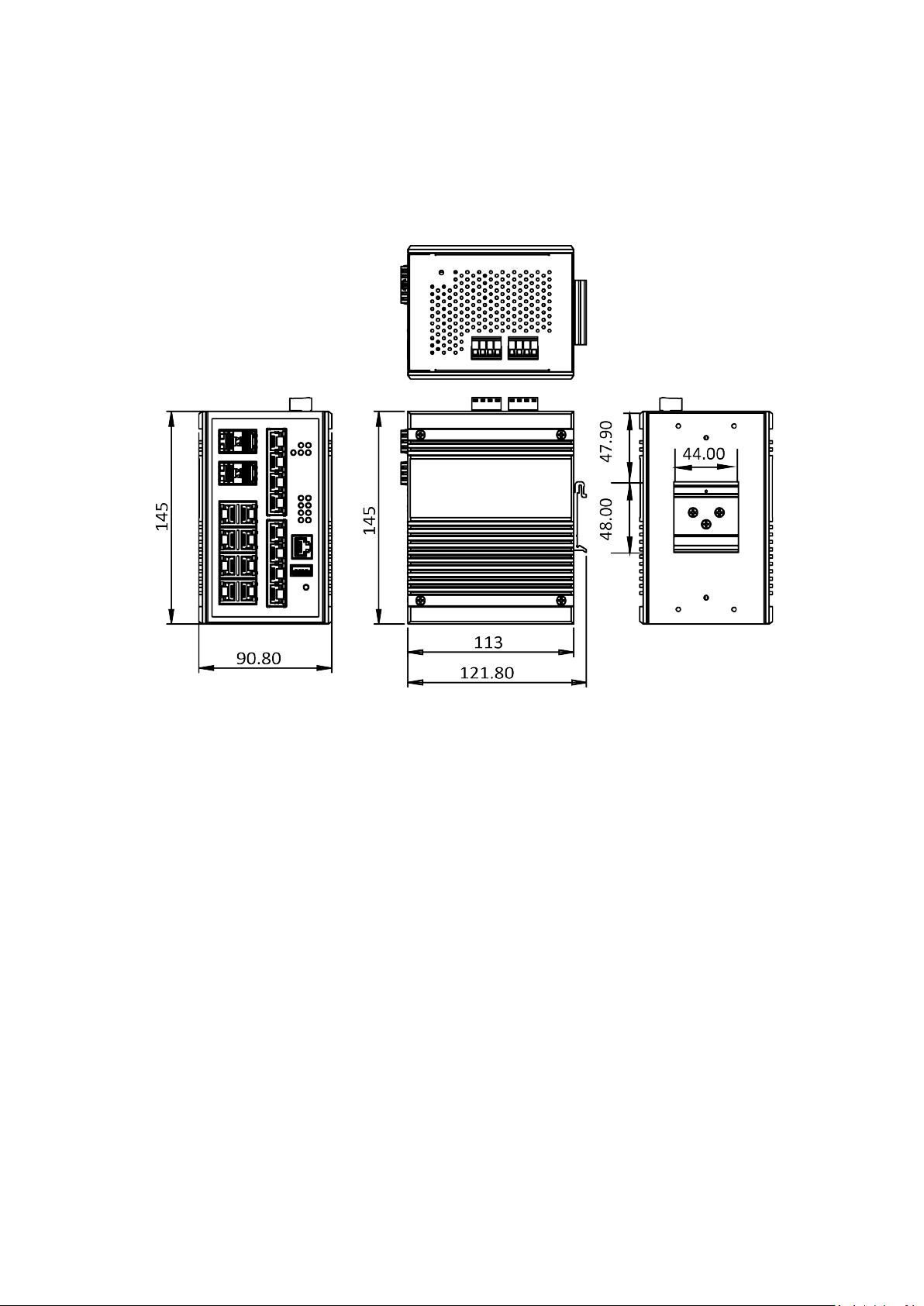
I-3. Hardware Description
This section mainly describes the hardware of this switch and gives a physical and functional overview on the
certain switch.
Dimension
The dimension of this Switch is 145 mm (H) x 90.8 mm (W) x 113 mm (D). The figure down below is the drawing
of detail mechanical design:
6
Page 11
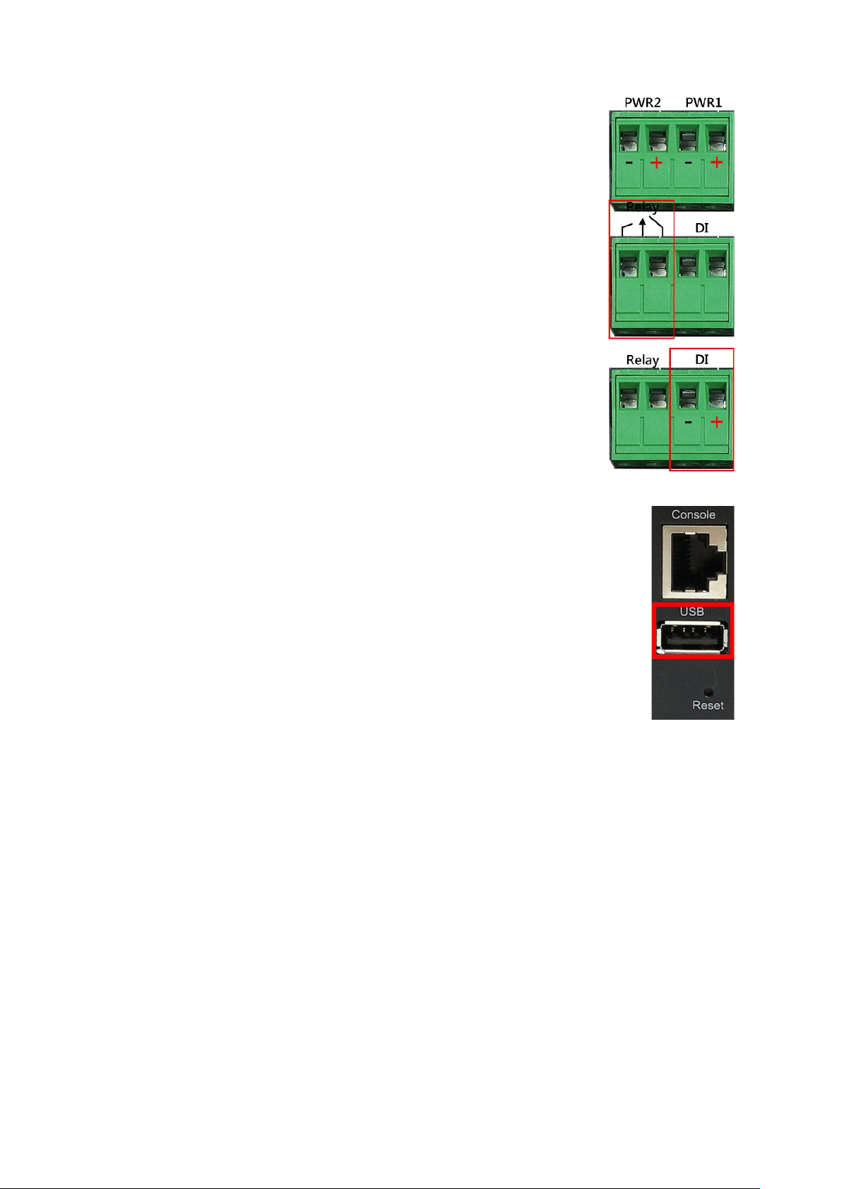
Wiring Power Inputs
1. Insert the positive and negative wires into the PWR1 (+,-) and
PWR2 (+,-) on the 4-contact terminal block connector.
2. Tighten the screws to prevent the wires from loosening.
Wiring Fault Alarm
1. Insert the wires into the left two contacts of the 4-contact
terminal block (Fault Alarm Relay).
2. Tighten the screws to prevent the wires from loosening.
3. The relay will detect the power and link failure.
4. Users can connect the relay to an alarm and buzzer so that when
the relay forms an open circuit, the users will be notified.
Wiring Digital Inputs
Insert the positive and negative wires into the right two contacts (+,-) of the
4-contact terminal block (DI).
1. Tighten the screws to prevent the wires from loosening.
2. The system will detect the voltage go through the DI.
• +13 to +30V for state "1"
• -30 to +3V for state "0"
• Max. input current: 8mA
USB Port
A USB port is available on the switch that is located between the Console port and
Reset button. This USB port provides the following features:
• Backup/Restore Configurations
• Auto-Load configuration from USB
• Auto-Backup configuration to USB
• Save system logs to USB
7
Page 12
LED
Color
Status
Description
On
Power is supplied on the power input 1.
Power is not supplied on the power input
On
Power is supplied on the power input 2.
Power is not supplied on the power input
2.
The system boots up and in normal
operation.
The system is powered off or during
The configured event of failure is
triggered.
On
This device has the Ring Master.
Off
The Ring Master is not on the device.
The Ring protocol is enabled and works
normally.
The Ring protocol is enabled, but works
abnormally.
Off
The Ring protocol is disabled.
The 1000Mbps link of the fiber port is
active.
Data is transmitted on the fiber port
at 1000Mbps.
The 1000Mbps link of the fiber port is
inactive.
The 1000Mbps link of the port is
active.
Data is transmitted on the port at
1000Mbps.
The 1000Mbps link of the port is
inactive.
The 10/100Mbps link of the port is
active.
Data is transmitted on the port at
10/100Mbps.
The 10/100Mbps link of the port is
inactive.
An IEEE 802.3at/af powered device is
connected.
No IEEE 802.3at/af powered device is
connected.
Press Time (Sec)
Action
Save the running configuration to the USB device named
4
Reboot the system.
More than 7
Reset the system to factory default and reboot it.
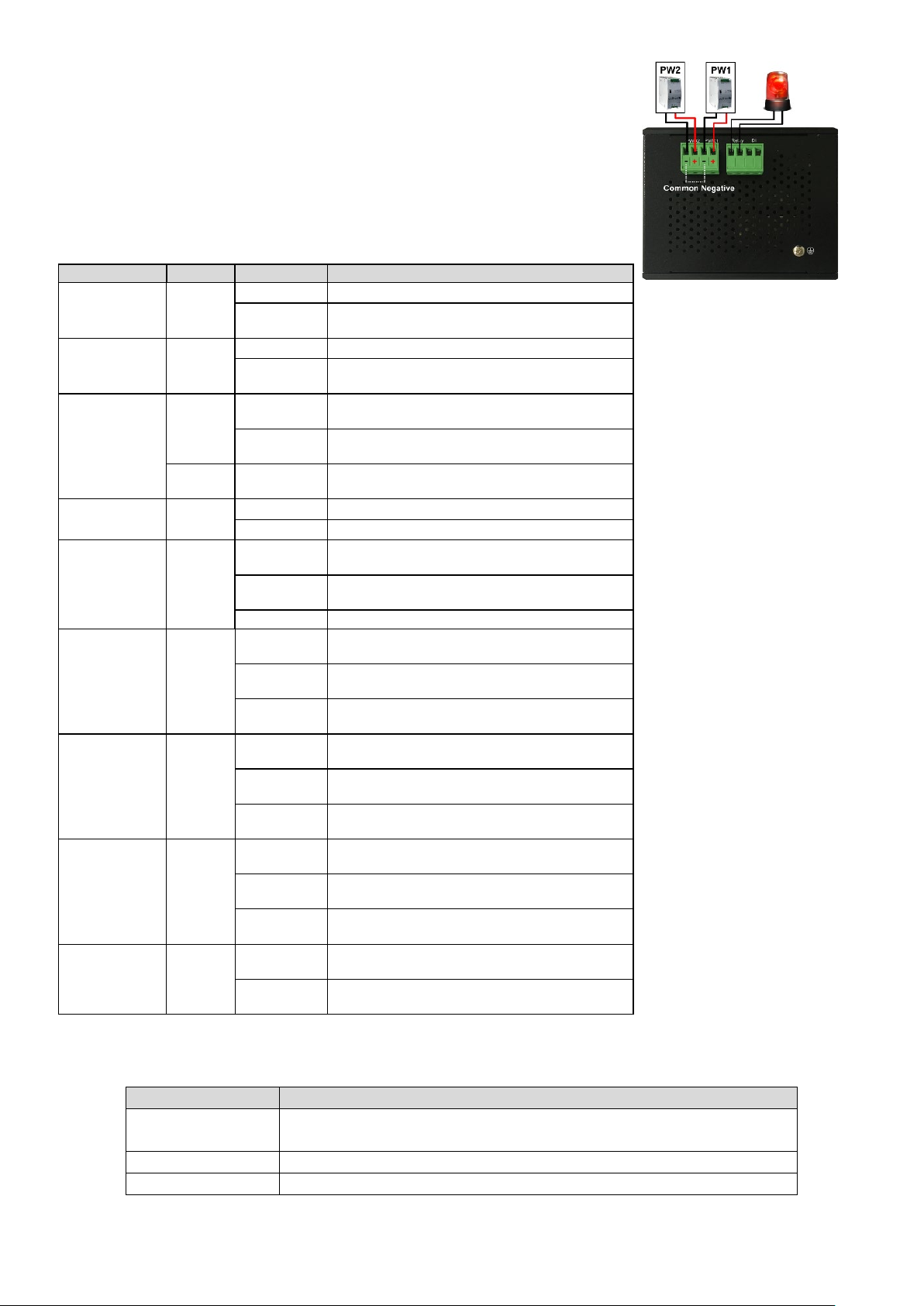
Double-Secure Power Input Fault Alarm
The power inputs are designed as a "common negative", which implies
that the negative input is connected, but "double-secure" is supported to
prevent the un-notified failure of power from one of the negative inputs.
If one of the negative power input fails, the system will detect it and the
system will trigger the event if the users set the fault alarm or event log
for powers.
LED Status
PWR1 Green
PWR2 Green
Fault
RM Green
Ring Green
SFP Slot
P17 to P20
(1000M)
LAN Port
P1 to P16
(1000M)
Green
Red On
Flickering
Green
Green
Flickering
Flickering
Off
Off
On
Off
On
On
Off
On
Off
1.
booting.
On
LAN Port
P1 to P16
Green
Flickering
(10/100M)
Off
PoE+
P1 to P8
Reset Button
A multifunctional reset button is provided. Use a pointed object such as toothpick or paper clip
(straightened) to press the reset button.
Amber
1
On
Off
"running-config".
8
Page 13
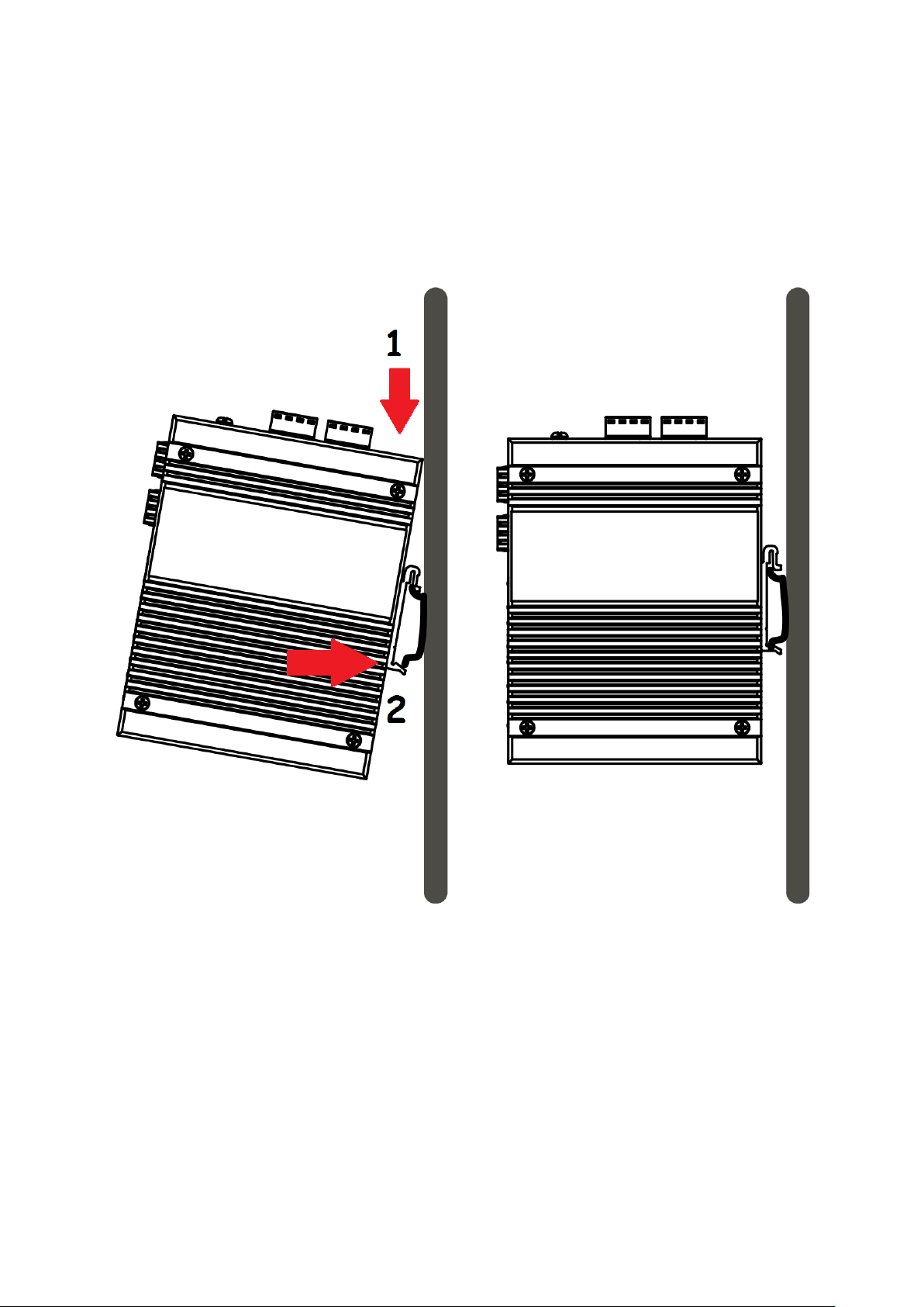
I-4. DIN-Rail Mounting
The DIN-Rail clip is already attached on the rear side of the switch supports EN 50022 standard DIN Rail,
in the following diagram includes the dimension of EN 50022 DIN Rail.
Follow the steps below to mount the switch on the DIN-Rail track.
1. Insert the upper end of the DIN-Rail clip into the back of the DIN-Rail track from its upper side
2. Lightly push the bottom of the DIN-Rail clip into the track.
3. Check if the DIN-Rail clip is tightly attached to the track.
4. To remove the switch from the track, reverse the steps above.
9
Page 14

I-5. Console Connection
The Console port is for local management by using a terminal emulator or a computer with terminal emulation software.
DB9 connector connect to computer COM port
Baud rate: 115200bps
8 data bits, 1 stop bit
None Priority
None flow control
I-6. Connecting Cable
The port 1~16 is the copper ports, it requests UTP/STP cable.
The port 17 ~ 20 are the SFP slots, purchase the suitable fiber transceiver from your supplier and
connect the fiber cable for the link.
Ethernet cable Request
The wiring cable types for data transmission are as below.
10 Base-T: 2 -pair UTP/STP Cat. 3, 4, 5 cable, EIA/TIA-568 100-ohm (Max. 100m)
100 Base-TX: 2-pair UTP/STP Cat. 5 cable, EIA/TIA-568 100-ohm (Max. 100m)
1000 Base-T: 4 -pair UTP/STP Cat. 5 cable, EIA/TIA-568 100-ohm (Max. 100m)
The wiring cable types for data transmission and power delivery in any speed are Cat. 5 or above.
SFP Installation
1. Insert the SFP module. A triangle is available on the switch and SFP module.
2. Push the SFP module down.
10
Page 15

II. Preparing for Management
This section will guide your how to manage this product via serial console, management web page, and
Telnet/SSH interface.
The switch provides both out-of-band and in-band managements.
Out-of-band Management: You can configure the switch via RS232 console cable without having the switch or
your PC connecting to a network. Out-of-band management provides a dedicated and secure way for switch
management.
In-Band Management: In-band management allows you to manage your switch with a web browser (such as
Microsoft IE, Mozilla Firefox, or Google Chrome) as long as your PC and the switch are connected to the same
network.
Preparation for Serial Console
Preparation for Web Interface
Preparation for Telnet/SSH Interface
11
Page 16
II-1. Preparation for Serial Console
Inside the product package, you can find an RS-232 console cable. Before managing your switch via
out-of-band management, please attach this cable’s RJ45 connector to your switch’s console port and its
RS-232 female connector to your PC’s COM port.
To access this switch’s out-of-band management CLI (Command Line Interface), your PC must have
terminal emulator software such as HyperTerminal or PuTTY installed. Some operating systems (such as
Microsoft Windows XP) have HyperTerminal already installed. If your PC does not have any terminal
emulator software installed, please download and install a terminal emulator software on your PC.
The following section will use HyperTerminal as an example.
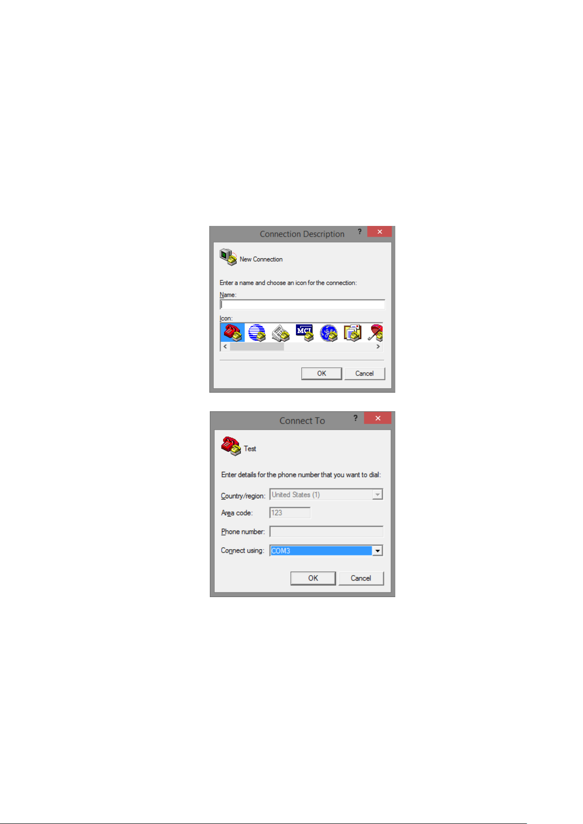
1. Run HyperTerminal on your PC.
2. Give a name to the new console connection.
3. Choose the COM port that is connected to the switch.
12
Page 17
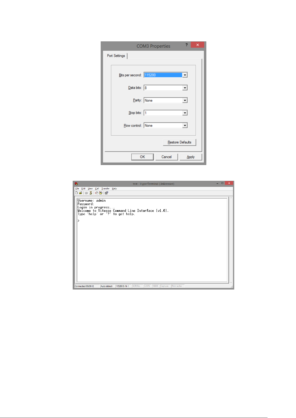
4. Set the serial port settings as: Baud Rate: 115200, Data Bit: 8, Parity: None, Stop Bit: 1, Row
Control: None.
5. The system will prompt you to login the out-of-band management CLI. The default
username/password is admin/admin.
13
Page 18
II-2. Preparation for Web Interface
The management web page allows you to use a web browser (such as Microsoft IE, Google Chrome, or
Mozilla Firefox) to configure and monitor the switch from anywhere on the network.
Before using the web interface to manage your switch, please verify that your switch and your PC are on
the same network. Please follow the steps down below to configure your PC properly:
1. Verify that the network interface card (NIC) of your PC is operational and properly installed, and
that your operating system supports TCP/IP protocol.
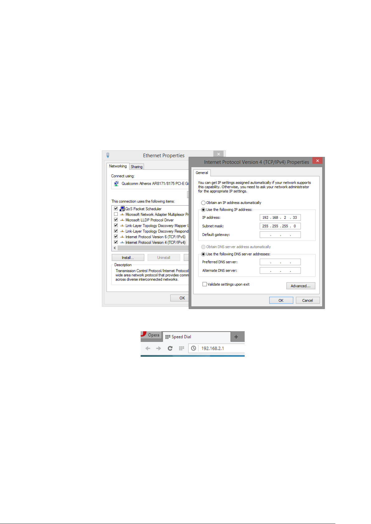
2. Connect your PC with the switch via an RJ45 cable.
3. The default IP address of the switch is 192.168.2.1. The switch and your PC should locate within
the same IP Subnet. Change your PC's IP address to 192.168.2.X, where X can be any number from
2 to 254. Please make sure that the IP address you’ve assigned to your PC cannot be the same with
the switch.
4. Launch the web browser (IE, Firefox, or Chrome) on your PC.
5. Type 192.168.2.1 (or the IP address of the switch) in the web browser’s URL field, and press Enter.
14
Page 19

6. The web browser will prompt you to sign in. The default username/password for the configuration
web page is admin/admin.
For more information, please refer to Appendix B: IP Configuration for Your PC.
15
Page 20
II-3. Preparation for Telnet/SSH Interface
Both telnet and SSH (Secure Shell) are network protocols that provide a text-based command line
interface (CLI) for in-band system management. However, only SSH provides a secure channel over an
un-secured network, where all transmitted data are encrypted.
This switch support both telnet and SSH management CLI. In order to access the switch’s CLI via telnet or
SSH, both your PC and the switch must be in the same network. Before using the switch’s telnet/SSH
management CLI, please set your PC’s network environment according to the previous chapter (II-2.
Preparation for Web Interface).
Telnet interface can be accessed via Microsoft “CMD” command. However, SSH interface can only be
accessed via dedicated SSH terminal simulator. The following section will use PuTTY as an example to
demonstrate how to connect to the switch’s SSH CLI, since both telnet and SSH uses the same way
(though using different terminal simulator software) to access in-band management CLI.
Access SSH via Putty:
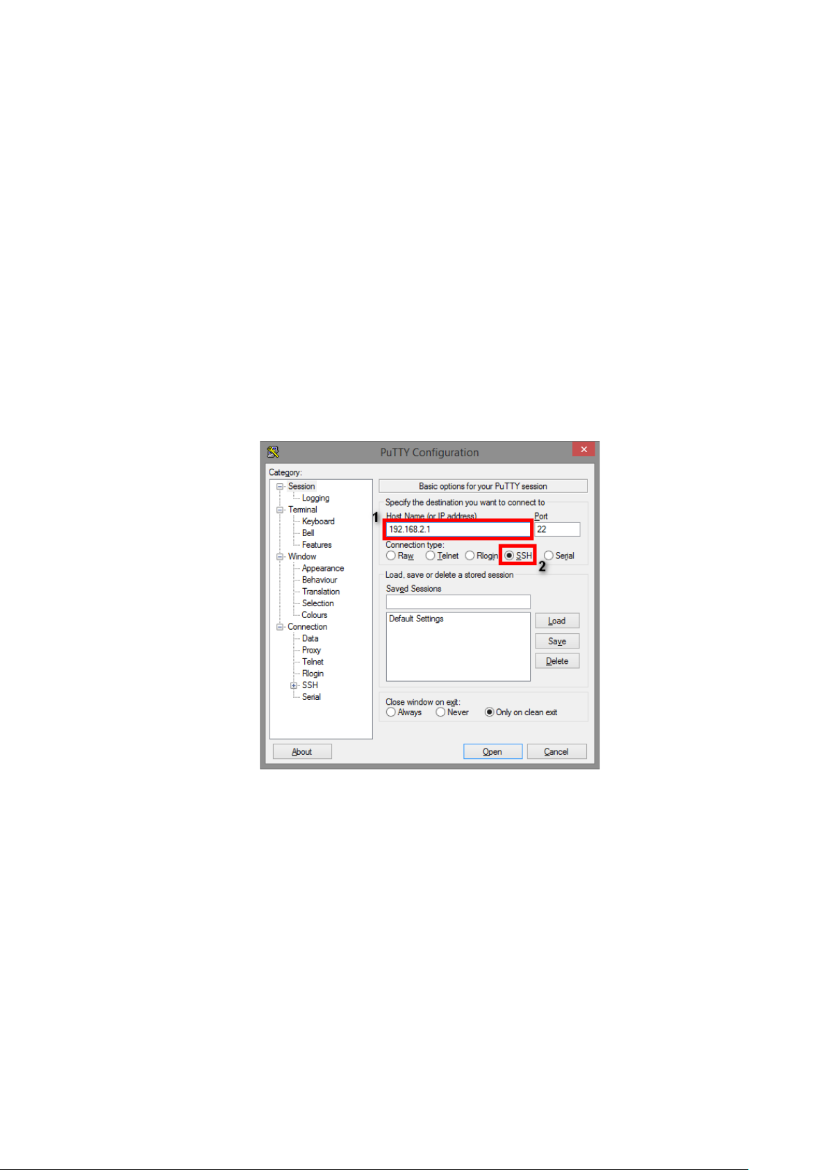
A “PuTTY Configuration” window will pop up after you run PuTTY.
1. Input the IP address of the switch in the “Host Name (or IP address)” field. The default IP address
of the switch is 192.168.2.1.
2. Choose “SSH” on the “Connection type” section, then press “Enter”.
16
Page 21
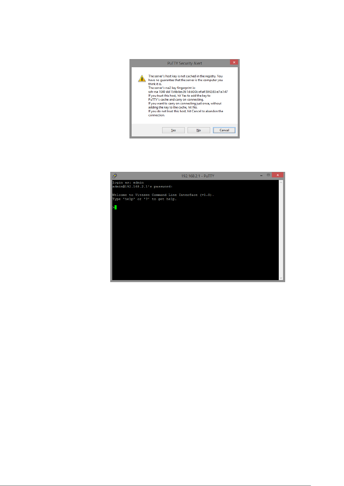
3. If you’re connecting to the switch via SSH for the first time, a “PuTTY Security Alert” window will
pop up. Please press “Yes” to continue. This window won’t pop up if you’re using telnet to connect
to the in-band management CLI.
4. PuTTY will prompt you to login after the telnet/SSH connection is established. The default
username/password is admin/admin.
17
Page 22
III. Web Management
As mentioned in Chapter II-2 Preparation for Web Interface, This switch provides a web-based management
interface. You can make all settings and monitor system status with this management web page.
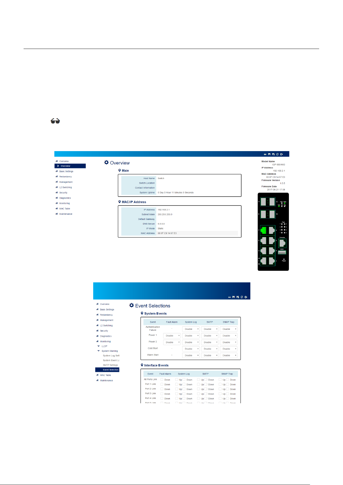
III-1. Web Management - Overview
When you log in, the configuration web page will display current system status.
1. Hide/Show Model Information
When a low-resolution environment is used to configure the system via the web console, the "Model
Information" field can be hidden to have a better view.
Show Model Information:
Hide Model Information:
18
Page 23
2. Save Configuration
After configuring, click the icon to save the configurations to the "startup-config" file. The configurations
are retained in the system until a factory reset default is done.
3. Restore Factory Default
Removes the configurations saved in the system. After restoring factory default, all the settings will be
set to default values.
4. Reboot System
Reboots the device and restarts the system.
5. System Logout
This option enables you to sign out from the system. Users have to login again if they want to configure
the settings.
The system will auto-logout after the "timeout" timer expires. The "timeout" timer is configured in the
CLI mode by using the "exec-timeout" command.
The maximum value of the timer in the web console is 30 minutes.
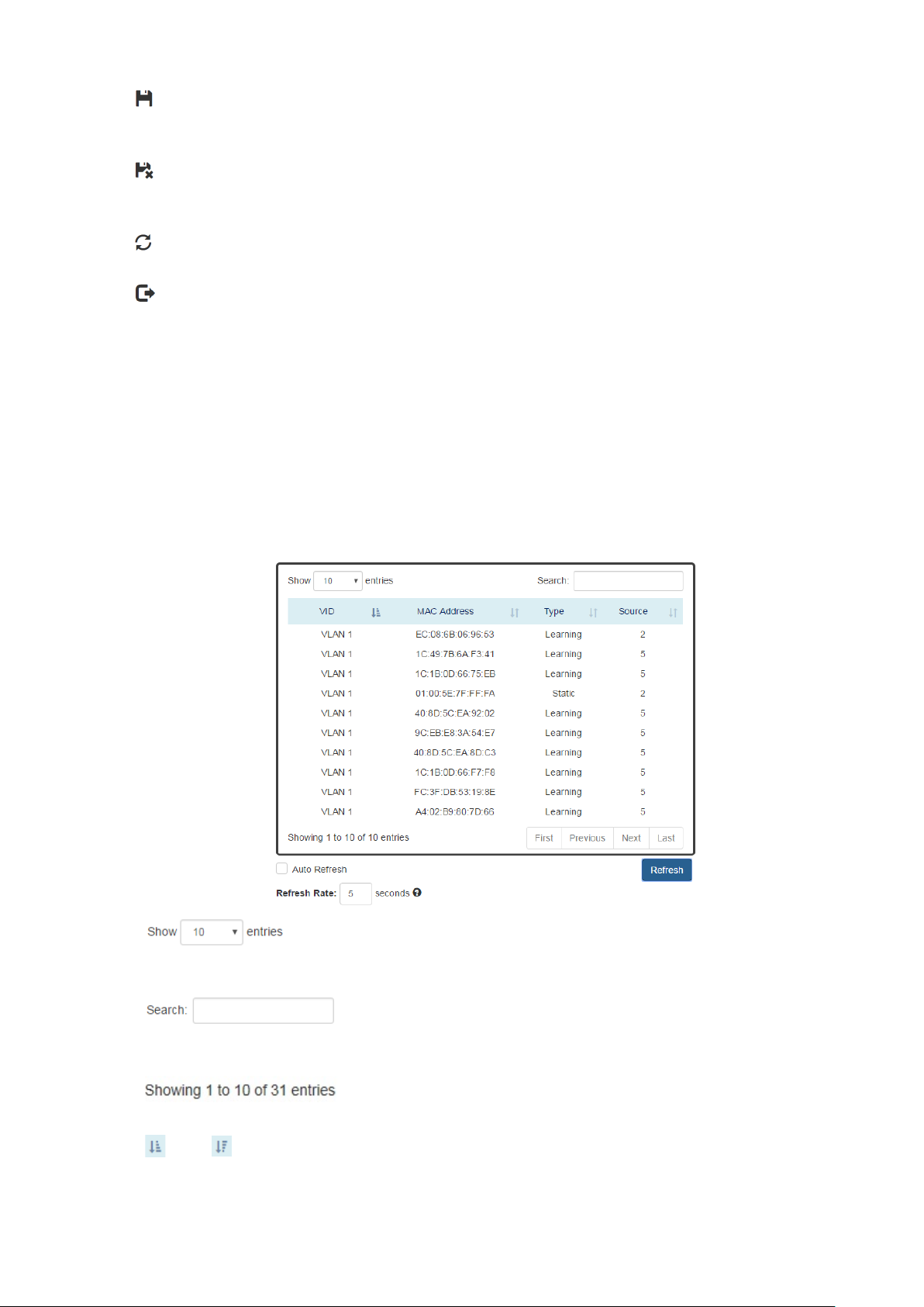
A USER-FRIENDLY DATA TABLE
A user-friendly data table is provided on the“IPv6 Neighbor Table”, “IGMP Snooping Table”, “VLAN
Table”, “ LLDP Neighbor Table”, and “MAC Address Table”. The following section details how to use the
data table functions to help the users to observe the information easily.
The following example is “MAC Address Table”.
•
Users will be able to select a value to display the number of entries in one page. The following values
can be selected - “10”, “ 25”, “50”, and “100” selections. By default, “10” is selected.
•
The search option enables you to search a key word in the data. It will search all the columns and
identify the data rows that match the search criteria.
•
It displays the total number of entries and the current entry number.
•
and
This option orders the field from smaller to larger or from larger to smaller.
19
Page 24

•
Changes to “First”, “Previous”, “Next”, or “Last” page.
In addition to the above functions, “Refresh” and “Auto Refresh” function are available for all status
page including “IPv6 Neighbor Table”, “RSTP Port Status”, “Port Status”, “ IGMP Snooping Table”,
“VLAN Table”, “ Trunking Status”, “ LLDP Neighbor Table”, and “MAC Address Table”.
•
Selecting this checkbox enables the “Auto Refresh” function and deselecting the checkbox disables
the “Auto Refresh” function.
•
The Refresh Rate option is a global configurable variable. When the Auto Refresh option is enabled,
the status will refresh automatically based on the Refresh Rate interval.
The range of the Refresh Rate is from 5 to 300 second(s).
The default Refresh Rate is 5 seconds.
•
(Refresh Button)
You can click the “Refresh” button to manually refresh the status.
20
Page 25
III-2. Web Management – Basic Settings
III-2-1. BASIC SETTINGS - SYSTEM
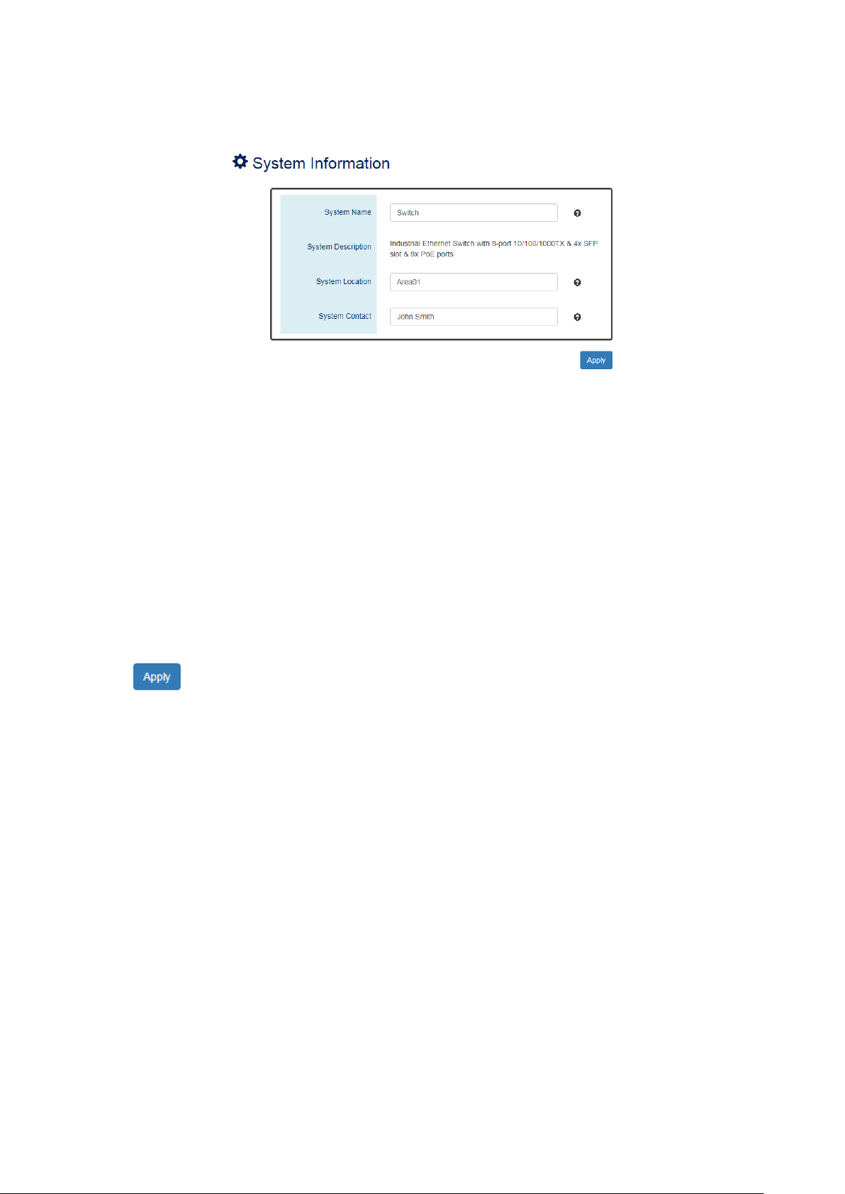
CONFIGURE SYSTEM INFORMATION
Host Name
•
It is useful to identify the difference between the switches, for example: CoreSwitch01.
The max length for the Host Name is 32 alphanumeric characters.
Device Description
•
The Device Description is fixed and defined by the system.
It contains the copper port number, fiber port number, and PoE information (if supported).
Switch Location
•
It is useful to find the location of the switches, for example: Area01.
The max length for the Switch Location is 32 alphanumeric characters.
Contact Information
•
Information of the person responsible for this device and the contact details. Only alphanumeric
characters can be used here.
•
(Apply Button)
After configuring above fields, click "Apply" button to make the changes effective.
21
Page 26
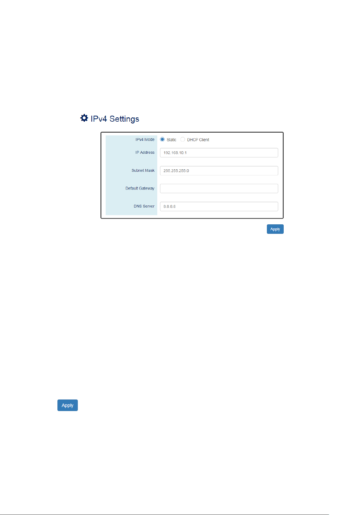
III-2-2. BASIC SETTINGS – IPV4 SETTINGS
Internet Protocol Version 4 (IPv4) is the fourth version of the Internet Protocol. It is used on the
packet-switched networks and with connectionless communication. IPv4 has four bytes (32 bits) address
and the address space is limited to 4,294,967,296 (232) unique addresses. On the local area network
(LAN), the “Private Network” is used. It starts from 192.168.0.0 and the address space contains 65,025
(216) IP addresses. The frames can only be sent to the host in the same subnet. For example, the default
IP Address of the switch is “192.168.2.1”.When the users want to connect to the web console of the
switch, an IP address from “192.168.2.2” to “192.168.2.254” must be assigned to the host.
CONFIGURE IPV4 INFORMATION
IPv4 Mode
•
There are 2 ways to configure IPv4 address - one is to configure a static IP address manually and
another one is to get an IP address by DHCP.
If the IPv4 mode is "DHCP Client", IPv4 information fields will be set to "Disabled".
IP Address
•
Assigns a unique static IP Address in the subnet to access the system.
The default IP Address is "192.168.2.1".
Subnet Mask
•
Defines the type of network, to which this device is connected to.
The default Subnet Mask is "255.255.255.0".
Default Gateway
•
The IP address of the router used to connect a LAN to a WAN.
DNS Server
•
Specifies the IP address of the DNS Server so that the users can connect to another device based on
the URL instead of the IP address.
The default DNS Server is "8.8.8.8". It is provided by Google.
•
(Apply Button)
After configuring above fields, click "Apply" button to make the changes effective.
22
Page 27
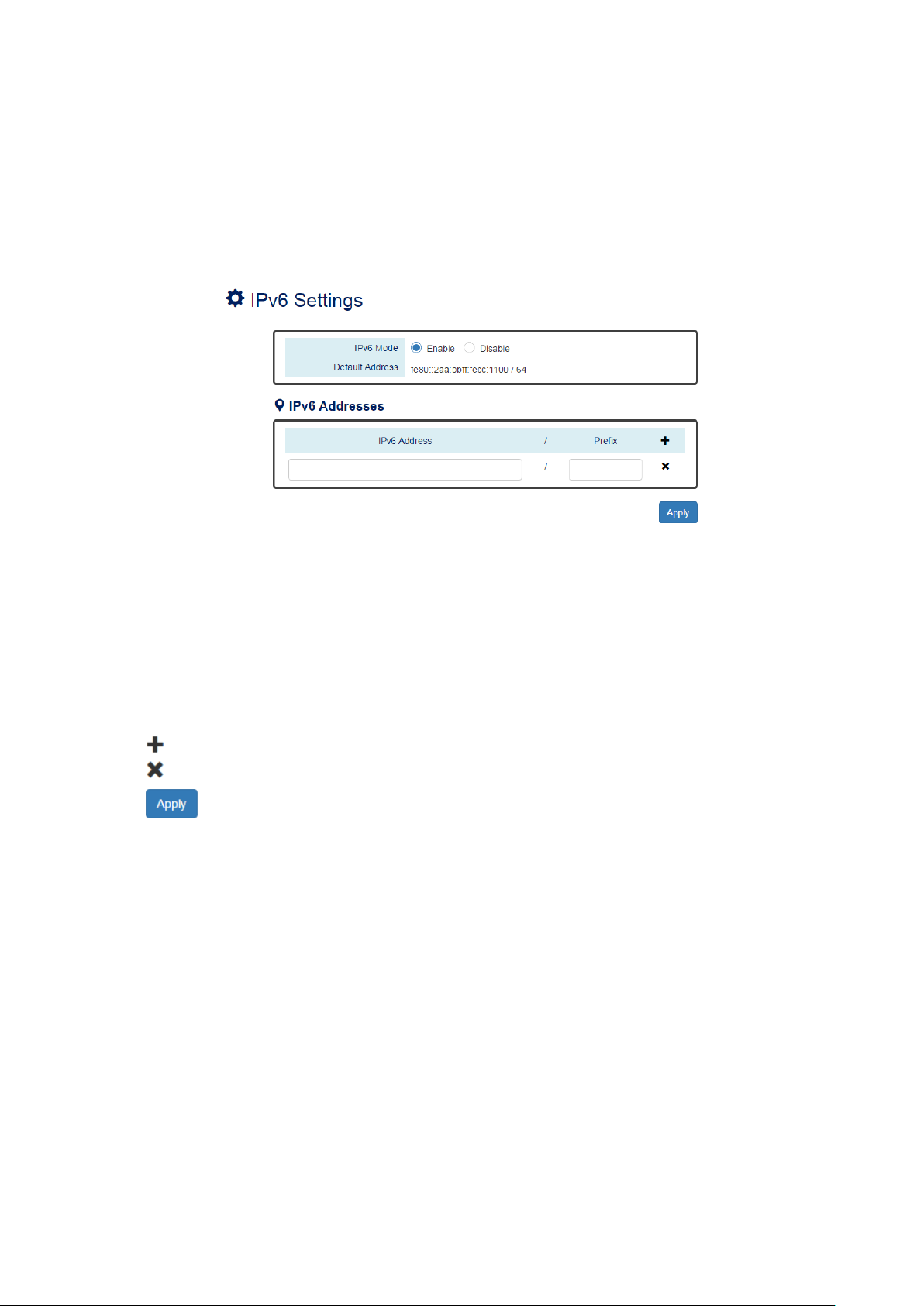
III-2-3. BASIC SETTINGS – IPV6 SETTINGS
Internet Protocol Version 6 (IPv6) is a solution to deal with the address space limitation of IPv4 and it is
the most recent version of Internet Protocol. It is intended to replace IPv4. IPv6 is a Layer 3 (Internet
Layer) protocol, which is used on the packet-switched networks and with connectionless communication.
There are 16 bytes (128 bits) for an IPv6 address and the address space is up to 2
The IPv6 address is usually represented in hexadecimal digits, 8 groups of 4 digits, and each group is
separated by a “:” (colon). For example, the DNS server address in IPv6 is
“2001:4860:4860:0000:0000:0000:0000:8888”.
CONFIGURE IPV6 INFORMATION
128
unique addresses.
IPv6 Mode
•
"Enable" or "Disable" IPv6. When the IPv6 Mode is enabled, other devices can connect to this unit.
Default Address
•
This is the Default IPv6 Address for this device. It is a Link-Local address and is automatically
generated from the MAC Address of the device.
IPv6 Addresses
•
Enables the users to define other IPv6 addresses for this device.
The IPv6 address contains 2 sections - IPv6 address and prefix. The default Prefix is 64-bit.
: Click the plus icon to add an IPv6 Address row.
: Click the remove icon to delete the IPv6 Address row.
•
(Apply Button)
After configuring above fields, click "Apply" button to make the changes effective.
23
Page 28

IPV6 NEIGHBOR TABLE
IPv6 Address
•
This filed displays the IPv6 address of the neighbor.
MAC Address
•
This filed displays the MAC address of the neighbor.
State
•
The connection state can be “DELAY”, “REACHABLE”, “STALE”, “FAILED”, or “PROBE”.
24
Page 29
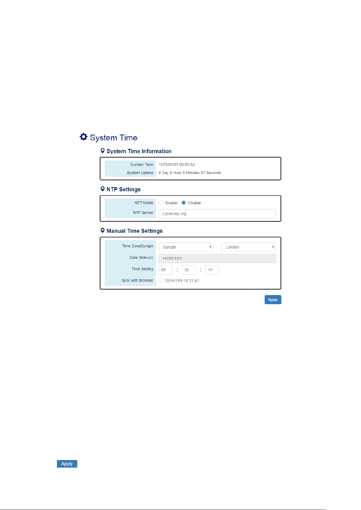
III-2-3. BASIC SETTINGS – SYSTEM TIME
The System Time represents the date and time. The system uptime defines the passing time after the
system boots up. There is no battery on the switch and hence the system time cannot be saved in the
system. Users can configure the time zone and system time manually by synchronizing the time with the
browser or by enabling the “NTP” service to get the time from a NTP Server.
NTP
Network Time Protocol (NTP) is a clock synchronization protocol, which is used to synchronize the
system time with the NTP server. NTP is one of the oldest Internet Protocols in use from 1985 until now.
It works based on a client-server model, but it can also be used in peer-to-peer relationships. The NTP
application on the switch is follows the client-server model and the switch plays a role in the NTP Client.
CONFIGURE SYSTEM TIME INFORMATION
YSTEM TIME INFORMATION
S
•
。 Current Time: The current date time of the system.
。 System Uptime: The system boot up duration.
NTP Settings
•
。 NTP Mode
"Enable" or "Disable" NTP Service. If NTP Mode is enabled, the system will sync time with NTP
Server on an hourly basis.
。 NTP Server
This field displays the URL or the IP address of the host that provides the NTP Service.
Manual Time Settings
•
。 Time Zone
Select the Time Zone to define the local time offset from GMT.
。 Date Selector
Select the system date manually. The format is "year/month/day".
。 Time Setting
Define the system time manually. The format is "hour:minute:second".
。 Sync with Browser
Select the checkbox to synchronize the system time with the browser time.
•
(Apply Button)
After configuring above fields, click "Apply" button to make the changes effective.
25
Page 30

III-3. Web Management – Redundancy
III-3-1. REDUNDANCY – SPANNING TREE
The Spanning-Tree Protocol is a standard protocol that is defined in IEEE 802.1D. It is used to build
a logical loop-free topology for layer-2 Networks. The basic function of the protocol is to prevent loops
and broadcast flooding around the switches. STP allows spare links in the network design to
provide backup paths when the active link fails and requires a convergence time of 30-50 seconds to
recover the topology when the topology is changed. This prompted the use of Rapid Spanning-Tree
Protocol as it provides a faster convergence when the topology is changed.
RSTP was introduced by IEEE as 802.1w. It can respond within 3 x "Hello Time" when a topology is
changed. The "Hello Time" is a configurable value and it is very important for RSTP. The default RSTP
value is 2 seconds and typically, the convergence time for RSTP is under 6 seconds. RSTP is much faster
than STP. RSTP should be used instead of STP.
The Multiple Spanning-Tree Protocol defined in the IEEE 802.1s is an extension to RSTP for Virtual LANs.
MSTP provides a better alternate path than STP/RSTP for different VLANs. It can make a group of VLANs
more systemized in the topology.
C
ONFIGURE RSTP BASIC INFO R M AT ION
System Time Information
•
RSTP: Enable STP and run "RSTP" for redundancy.
MSTP: Enable STP and run "MSTP" for redundancy.
Disable: Disable STP. Users have to enable another protocol to prevent from loop.
Root Priority
•
It is used to define the "Root Bridge". The bridge with the lowest Root Priority is the "Root Bridge".
If all the bridges are set to the same Root Priority value, the system will select the Root Bridge based
on the MAC Addresses.
The range of Root Priority is from 0 to 61440(multiple of 4096).
The default Root Priority is 32768.
Hello Time
•
It is very important and used to determine the interval to send BPDU (management frame) to check
the RSTP topology and status.
The range of Hello Time is from 1 to 10 second(s).
The default Hello Time is 2 seconds.
Forward Delay
•
A delay/timer is used to determine when to change the Path State from Learning/Listening to
Forwarding.
The range of Forward Delay is from 4 to 30 seconds.
The default Forward Delay is 15 seconds.
26
Page 31

Maximum Age
•
A timer that is used to wait for the Hello BPDU from the Root Bridge. If this device receives the BPDU
before the timer expires, the timer will be reset. Else, the device will send the topology changed
BPDU to notify other devices.
The range of Maximum Age is from 6 to 40 seconds.
The default Maximum Age is 20 seconds.
Note: The relationship between "Hello Time", "Forward Delay", and "Maximum Age" is:
2 x (Forward Delay - 1 sec) >= Max Age >= 2 x (Hello Time + 1 sec)
27
Page 32

CONFIGURE RSTP PORT IN FORM AT I O N
No.
•
Port1 to PortN, where N is based on the total port number.
Path Cost
•
The cost from the current node to another device.
The range of Path Cost is from 0 to 200000000.
The default Path Cost is 0. This implies that the Path Cost is decided by the system.
Port Priority
•
Used to decide the port to be blocked in the Ring topology.
The range of Root Priority is from 0 to 240 and are in multiple of 16.
The default Root Priority is 128.
Admin P2P
•
The Admin P2P is the link-type for each port.
P2P: It is a full-duplex link.
Shared: It is a half-duplex link.
Edge
•
A port that can connect to a non-STP device is called an Edge port. Users can manually fix a port to
non-Edge or Edge.
Auto: The system automatically identifies an Edge or Non-Edge.
Edge: The port is forced to be an Edge port. An edge port will directly be transitioned to the
"Forwarding" state and is not required to wait for the "Forward Delay". If a port is directly connected
to a non-STP device, users can manually set it to "Edge" and enable it to transmit faster.
Non-Edge: The port is forced to be a Non-Edge port. This implies that the port will go through
Learning/Listening to Forwarding state even though it is connected to an end device or not.
Admin STP
•
"Enable" or "Disable" the Spanning-tree protocol that is running on the specific port.
•
(Apply Button)
After configuring above fields, click "Apply" button to make the changes effective.
28
Page 33

RSTP STATU S
Bridge ID
•
This field shows the unique identity of this node when it is part of a network. It contains 8 bytes the first 2 bytes are for Bridge Priority (configurable) and the remaining 6 bytes are for the MAC
Address (unique).
Root Bridge
•
It is elected from the switches in the STP topology via several STP messages (BPDU). The Root Bridge
is the node with the lowest Root Priority. If all of the nodes are with the same Root Priority, the
Root Bridge will be selected based on their MAC Addresses.
Root Priority
•
It is used to define the "Root Bridge". The bridge with the lowest Root Priority is the "Root Bridge".
If all bridges are set to the same Root Priority value, the system will select the Root Bridge based on
the MAC Addresses.
Root Port
•
It is the port that is connected to the Root Bridge and with the lowest cost. If the Root Port shows
"none", it implies this node is the Root Bridge.
Root Path Cost
•
It is the cost from the current node to the Root Bridge.
Hello Time
•
It is used to determine the interval to send BPDU (management frame) to check the RSTP topology
and status.
Forward Delay
•
It is used to determine when to change the Path State from Learning/Listening to Forwarding.
Max Age
•
It is used during waiting for Hello BPDU from the Root Bridge.
29
Page 34

Speed
RSTP Path Cost
Speed
RSTP Path Cost
4 Mbps
5,000,000
1000 Mbps (1 Gbps)
20,000
10 Mbps
2,000,000
2000 Mbps (2 Gbps)
10,000
16 Mbps
1,250,000
10000 Mbps (10 Gbps)
2,000
100 Mbps
200,000
No.
•
Port 1 to Port N, N is based on the total port number.
Role
•
This field shows the role of the STP port.
Root: This is the root port, which is connected to the Root Bridge with the lowest cost.
Designated: This is the designated port, which can send the best BPDU on the segment to other
connected nodes.
Alternate: This is the alternate port, which is blocked. This port can still receive useful BPDU from
another bridge. When it receives a useful BPDU, it will help to forward it on the segment.
Backup: This is the backup port, which is blocked. It corresponds with “Alternate Port” to the
blocking state. This port also receives useful BPDU, but the BPDU is from the same bridge. When it
receives a useful BPDU, it will help to forward it on the segment.
Disabled: The port is not linked up.
Path State
•
This field shows the path state of this STP port.
Discarding: The port state can be “Disabled”, “Blocking”, or “Listening”. The incoming frames are
dropped and learning MAC addresses are stopped.
Learning: The port is learning MAC addresses, but the incoming frames are dropped.
Forwarding: The port in the forwarding state forwards the incoming frames based on the learned
MAC address table.
Port Cost
•
This is the cost from the port to the Root Bridge. Spanning-tree Protocol assumes the path cost is
determined by the access speeds of the links. The default RSTP path cost is shown in the following
table:
•
Port Priority
The Port Priority is used to determine the Root Port on a non-root bridge. The port with the lowest
Port Priority value gets the higher priority.
30
Page 35

Oper. P2P
•
This field shows the link-type of the STP port. P2P means “point-to-point” and Shared means
“point-to-multiple”.
Oper. Edge
•
This field shows the edge state of this STP port.
C
ONFIGURE MSTI INFORMATION
Basic Settings
•
。 Region Name
The Region Name is the name of the MST Region. The switches in the same MST Region must be
set to the same Region Name.
The max length for the Region Name is 32 characters.
Note: #, \, ', ", ? are invalid characters.
。 Revision Number
The Revision Number is the level of the MST Revision. The switches in the same MST Region must
be set to the same Revision Number.
The range of the Revision Number is from 0 to 65535.
The default Revision Number is 0.
31
Page 36

Instance Settings
•
。 Instance No.
The Instance No. is from 1 to 15.
。 Included VLAN
The configured VLANs are involved in the specific Instance.
The format is: 10, 20, 30…. “Comma” is used to separate VLAN IDs.
。 Priority
The priority is used to define the “Root Bridge” that is used to communicate with other MSTI
Region.
The range of the Root Priority is from 0 to 61440 (multiple of 4096).
The default Root Priority is 32768.
•
(Apply Button)
After configuring above fields, click "Apply" button to make the changes effective.
32
Page 37

CONFIGURE MSTI PORT IN FOR M AT I O N
Instance Selector
•
Select the instance to configure the ports. The Instance No. is from 1 to 15.
No.
•
Port1 to PortN, where N is based on the total port number.
Path Cost
•
The Path Cost is the cost from the current node to another device.
The range of the Path Cost is from 0 to 200000000.
The default Path Cost is 0. This implies that the Path Cost is decided by the system.
Port Priority
•
This is used to identify the port to be blocked in the Ring topology.
The range of the Root Priority is from 0 to 240 and is in multiples of 16.
The default Root Priority is 128.
•
(Apply Button)
After configuring above fields, click "Apply" button to make the changes effective.
33
Page 38

III-3-2. REDUNDANCY – ERPS
Ethernet Ring Protection Switching (ERPS) applies the protection switching mechanism for Ethernet
traffic in a ring topology. This mechanism is defined in ITU-T G8032. You can avoid the possible loops in
a network by implementing the ERPS function. This is done by blocking the flow of traffic to the Ring
Protection Link (RPL) for protecting the entire Ethernet ring.
When an ERPS is implemented in a ring topology, only one switch is allocated as the owner. This
switch is in charge of blocking the traffic in the RPL to avoid loops. The switch adjacent to the RPL owner
is called the RPL neighbor node and it is responsible for blocking the end of the RPL during normal
condition. The participating switches that are adjacent to the RPL owner or neighbor in a ring are called
the members or RPL next-neighbor nodes. The primary function of these switches is to forward the
received traffic.
To make sure that a ring is up and loop-free, Ring Automatic Protection Switching message is sent
regularly as control messages by nodes on the ring. The RPL owner identifies a signal failure (SF) in a
ring when the RPL owner misses the poll packets or reads from the fault detection packets. When the
fault is identified, the RPL owner unblocks the ring protection link (RPL) and permits the protected VLAN
traffic through.
ERPS, similar to STP, provides a loop-free network by using polling packets to detect faults. If a fault
occurs, ERPS restores itself by sending traffic over a protected reverse path rather than making a
calculation to identify the forwarding path. The fault detection mechanism in the ERPS enables the ERPS
to join in less than 50 milliseconds and recovers quickly to forward traffic.
34
Page 39

Role
Description
There is only one “Owner” in the ERPS ring topology. The Owner is
responsible for blocking the traffic in RPL and protects one side of the RPL.
There is only one “Neighbor” in the ERPS ring topology. The Neighbor is the
port connected with the Owner port and protects another side of the RPL.
The Interconnection port connects a major-ring and a sub-ring. If one of the
set to “Disabled” automatically.
None
The “None” implies that the port is other than an Owner or a Neighbor.
CONFIGURE ERPS INFORMATION
For more information, hover the mouse over the icon in the system.
ERPS Ring
•
There are three rings supported on a device. Using the dropdown select to change the ERPS Rings.
Basic Settings
•
。 ERPS Status
“Enable” or “Disable” ERPS protocol running on the switch. By default, the ERPS protocol is
enabled.
。 Ring Type
Configure the Ring to be a “Major-ring” or a “Sub-ring”.
。 ERPS Port 0
The ERPS Port 0 is also called “West Port”. Select one of the switch ports to be the Port 0 of ERPS
and decide the role of the port.
。 ERPS Port 1
The ERPS Port 1 is also called “East Port”. Select one of the switch ports to be the Port 1 of ERPS
and decide the role of the port.
Note: Only one of the switch ports can be configured as ERPS Port 0 or ERPS Port 1.
Owner
Neighbor
Interconnection
。 ERPS Ring ID
ports on the switch is set to “Interconnection” role, the other port will be
35
Page 40

The ID is the identifier of the ring. The members in the same ring must be set to the same ERPS
Ring ID.
The range of the ERPS Ring ID is from 1 to 239.
The default ERPS Ring ID is 1.
。 R-APS Channel
The R-APS Channel is used to forward ERPS information and is mapped to the VLAN IDs. These
VLAN IDs cannot be set as traffic VLANID. The members in the same ring must be set to the same
R-APS Channel.
The range of the R-APS Channel is from 1 to 4094.
The default R-APS Channel is 1000.
Advanced Settings
•
The Advanced Settings field is only displayed when the “Advanced Settings” checkbox is selected in
the Basic Settings.
。 Major-Ring Virtual Channel
This field is used to configure the specific virtual channel for transmitting the management
packets of the sub-ring through the major-ring.
。 Sub-Ring Virtual Channel
“Enable” or “Disable” using virtual channel in the sub-ring. When the Sub-Ring Virtual Channel is
enabled, ERPS protocol will transmit management packets by the configured virtual channel.
。 Revertive Mode
“Enable” or “Disable” the ERPS Revertive Mode. If the Revertive Mode is enabled, the blocked link
will revert to the RPL link after the failed link is recovered.
By default, the ERPS Revertive Mode is enabled.
。 MEL Value
MEL field is for the compliance with other devices which are running ITU-T G.8031from
third-party. The MEL implies the MEG Level. It is a field in the R-APS PDU. A large MEL value
involves more devices. For example, level 7 contains levels 0 to 6.
The range of the MEL Value is from 0 to 7.
The default MEL Value is 7.
•
(Apply Button)
After configuring above fields, click "Apply" button to make the changes effective.
36
Page 41

State
Description
Initial
The ERPS protocol is disabled in the selected ring.
The ERPS protocol is enabled in the selected ring and the ERPS ring is
under control by the RPL Owner.
The ERPS protocol is enabled in the selected ring. The ERPS ring is
recovery from Protection state and is waiting for the wtr timer expired.
The ERPS protocol is enabled in the selected ring but one of the links in
the ring is broken. The RPL changes to forward to keep the ring working.
ERPS STAT U S
ERPS Ring
•
There are three rings supported on a device. Using the dropdown select to change the ERPS Rings.
Basic Information
•
。 Ring Type
The type of the selected ERPS Ring shows “Major-ring”, “Sub-ring with virtual channel”, or
“Sub-ring without virtual channel”.
。 ERPS Status
The status of ERPS is “Enable” or “Disable” in the selected ERPS Ring.
。 Ring State
There are two states for ERPS Rings: Normal and Abnormal.
。 Node State
There are three states for ERPS Nodes: Initial, Idle, Pending, and Protection.
Idle
Pending
Protection
。 ERPS Ring ID
The ID is the identity for the selected ERPS Ring.
。 R-APS Channel
This field shows the configured R-APS Channel.
。 Virtual Channel
This field shows the virtual channel of sub-ring. If the field shows “default” implies the virtual
channel follows the R-APS Channel.
37
Page 42

。 Revertive Mode
Show the Revertive Mode is enabled (Yes) or disabled (No).
。 MEL Value
The field is the configured MEL value.
Port Status
•
。 Interface
The configured port presents the ERPS port 0/1 in the ERPS protocol.
。 Role
Display the configured role for the configured port.
38
Page 43

Version
Web Setting
Authentication
Encryption
Method
Read Only Community
Community String
No
String match for authentication
Read-Write Community
Community String
No
String match for authentication
Security Level –
Privacy
Access by an account (admin or
or SHA
Access by an account (admin or
to 32 characters.
III-4. Web Management – Management
III-4-1. MANAGEMENT – SNMP
Simple Network Management Protocol (SNMP) is a standard for collecting and structuring information
on the managed devices of the IP network. It can also modify some of the information to change the
behavior of the devices. SNMP is usually used in monitoring the network. The users can remotely query
the information provided by the devices running SNMP.
The switches support SNMP v1, v2c, and v3. SNMP v1 and v2c authenticates with a community string
for “read-only” or “read-write” permission. The SNMP v3 authentication requires the user to select an
authentication level (MD5 or SHA) and also supports data encryption to make the data safer.
For the SNMP version and authentication method relationship, refer to the table below:
v1 & v2c
v3
No Authentication, No
Security Level –
Authentication, No
Privacy
Security Level –
Authentication, Privacy
No No
MD5 / SHA No
MD5 / SHA
Yes
AES / DES
Access by an account (admin or
user)
user) and password with more than
8 characters, which is based on MD5
user) and password more than 8
characters, which is based on MD5
or SHA. The data encryption is based
on AES or DES and the key requires 8
39
Page 44

CONFIGURE SNMP SERVER IN FORM AT I O N
Basic Settings
•
。 SNMP Version
The system enables the SNMP “v1, v2c and v3” authentication by default. The users can enable
the SNMP server on only “v1 and v2c” or “v3”. “None” refers to disabling the SNMP server.
。 Read Only Community
The community used to access the SNMP server with the “read-only” privilege.
The max length for the Read Only Community is 32 characters.
Note: #, \, ', ", ? are invalid characters.
。 Read-Write Community
The community used to access the SNMP server with the “read-write” privilege.
The max.length for the Read-Write Community is 32 characters.
Note: #, \, ', ", ? are invalid characters.
SNMPv3 Settings
•
This section is displayed only when the SNMP Version is set to “v3” or “v1, v2c and v3”. Two
accounts are provided – Admin and User to access the SNMP agent. The users can set different levels
for the 2 accounts.
。 Security Level
No Authentication, No Privacy: Access by an account “admin” or “user”.
Authentication, No Privacy: Access by an account “admin” or “user” with password.
40
Page 45

Authentication, Privacy: Access by an account “admin” or “user” with password and the data will
be encrypted.
。 Authentication Type
Two algorithms are provided - MD5 and SHA for authentication password.
。 Authentication Password
A string/key is used to authenticate the SNMP Server and obtain the access permission. It will be
hashed by MD5 or SHA before authentication.
The min length for the Read-Write Community is 8 characters.
The max length for the Read-Write Community is 32 characters.
Note: #, \, ', ", ? are invalid characters.
。 Encryption Type
Two algorithms are provided - AES and DES for data encryption.
。 Encryption Password
A string/key is used to encrypt the data that is sent to the SNMP server.
The min length for the Read-Write Community is 8 characters.
The max length for the Read-Write Community is 32 characters.
Note: #, \, ', ", ? are invalid characters.
•
(Apply Button)
After configuring above fields, click "Apply" button to make the changes effective.
41
Page 46

CONFIGURE SNMP TRAP INFORMATION
Basic Settings
•
。 Trap M ode
The system enables the SNMP “v1, v2c and v3” authentication by default. Users can enable the
SNMP server only on “v1 and v2c” or “v3”. “None” indicates disabling the SNMP server.
。 Inform Retry
The SNMP trap will send “Retry” times when the trap set to “v2 Inform” or “v3 Inform” mode.
The range of the Inform Retry is from 1 to 100.
The default Inform Retry is 5.
。 Inform Timeout
The interval is used to send trap when the trap set to “v2 Inform” or “v3 Inform” mode.
The range of the Inform Retry is from 1 to 300 second(s).
The default Inform Retry is 1 second.
。 Trap Receiver IP
The IP address is the IP address of the trap server to receive the trap information.
。 Community
The string in the SNMP trap is the identity of the device.
The max length for the Community is 32 characters.
Note: #, \, ', ", ? are invalid characters.
SNMPv3 Trap/Inform Settings
•
This section is displayed only when Trap Mode are set to “v3 Trap” or “v3 Inform”.
。 Username
42
Page 47

Specify the username for authentication with the SNMP trap server.
。 Engine ID
The Engine ID is the identifier for the given SNMP application.
。 Security Level
No Authentication, No Privacy: Access using the username assigned to the users.
Authentication, No Privacy: Access using the username assigned to the users with password.
Authentication, Privacy: Access using the username assigned to the users with password and the
data will be encrypted.
。 Authentication Type
Two algorithms are provided - MD5 and SHA for authentication password.
。 Authentication Password
A string/key is used to authenticate the SNMP trap server and obtain the permission. It will be
hashed by MD5 or SHA before authentication.
The min length for the Read-Write Community is 8 characters.
The max length for the Read-Write Community is 32 characters.
Note: #, \, ', ", ? are invalid characters.
。 Encryption Type
Two algorithms are provided - AES and DES for data encryption.
。 Encryption Password
A string/key is used to encrypt the data sent to the SNMP trap server.
The min length for the Read-Write Community is 8 characters.
The max length for the Read-Write Community is 32 characters.
Note: #, \, ', ", ? are invalid characters.
•
(Apply Button)
After configuring above fields, click "Apply" button to make the changes effective.
43
Page 48

III-4-2. MANAGEMENT – DHCP
DHCP SERVER/CLIENT
DHCP, Dynamic Host Configuration Protocol, is a standardized protocol used in the IP networks. The
DHCP Server holds an IP address pool and when a DHCP Client request for an IP address, the DHCP
Server picks an IP address from the pool and assigns it to the client. DHCP Server also manages other IP
information such as Default Gateway and DNS Server. DHCP is very useful to configure the IP
information for a number of devices. Only the administrator can enable the DHCP Client for each device
and setup the DHCP Server. The clients will then obtain a unique IP address and other IP settings to
connect to the network.
DHCP
SERVER BINDING
Apart from dynamically allocating an IP address to a DHCP Client, the DHCP Server also provides a
function to manually assign a static IP address to the device with a specific MAC Address. This is called
as DHCP Server Binding.
DHCP
RE L AY/OPTION82
In a large network, there might be several subnets existed and the DHCP Client is not able to serve by
DHCP Servers directly. In this case, we need a relay agent to help to transmit the request frames to the
DHCP Servers. When a relay agent receives the broadcast request frame from a DHCP Client, the relay
agent will transmit the frame to the DHCP Servers, which are in the same subnet by unicast.
Option 82 is an information option to identify the clients by Circuit ID and Remote ID. The Circuit ID is
an identity containing the interface name and/or VLAN information, and the Remote ID is to identify
the remote host (the relay agent). The DHCP Server can distribute an IP address to the DHCP Client
according to Option 82 information and make the IP addresses more controllable.
The frame format for the Circuit ID is as below:
VLAN
•
The VLAN field is for the management VLAN ID, which is natively set to 1.
Module
•
The stack number for the device sending the DHCP request is on. For industrial switches, this byte is
always filled as0.
Port
•
The port number identifies the incoming DHCP request frame/DHCP Client.
The frame format for the Remote ID is as below:
MAC Address
•
By default, the MAC address is set to the MAC address of DHCP relay agent.
44
Page 49

CONFIGURE DHCP CLIENT
IPv4 Mode
•
Set the IPv4 Mode to “DHCP Client” to enable the DHCP Client. The system sends a discovery frame
to the network and tires to obtain an IP address from the DHCP Server.
After enabling the DHCP Client, users need to connect to the Console Port to get the IP address by
using “show ip address” on the CLI.
•
(Apply Button)
After configuring above fields, click "Apply" button to make the changes effective.
45
Page 50

CONFIGURE DHCP SERVER INFORMATION
Server Status
•
Shows the status of the DHCP server: Down or Up.
Server Mode
•
“Enable” or “Disable” the DHCP Server function.
Start IP Address
•
Set the range of the IP pool. The “Start IP Address” is the starting.
“Start IP Address” must be in the same subnet as that of the switch itself.
End IP Address
•
Set the range of IP pool. The “End IP Address” is the end.
“End IP Address” must be in the same subnet as that of the switch itself.
Default Gateway
•
Set the Default Gateway for the DHCP Clients to make them connect to the WAN.
“Default Gateway” must be in the same subnet as that of the switch itself.
DNS Server
•
Set the DNS Server for the DHCP Clients to make them connect to another device based on the URL
instead of IP address.
Lease Time
•
DHCP Server leases an IP address to a device for a period of time. When the lease time expires, the
DHCP server may assign a different IP address in the pool to the device.
•
(Apply Button)
After configuring above fields, click "Apply" button to make the changes effective.
46
Page 51

CONFIGURE DHCP SERVER BINDING INFORMATION
Binding ID
•
An ID used to identify the binding.
The range of the Binding ID is from 1 to 32.
MAC Address
•
The device with the specified MAC Address will be assigned to the static Binding IP Address.
Binding IP Address
•
A static IP Address will be assigned to the specified MAC Address.
•
•
•
: Click the plus icon to add a DHCP Binding row.
: Click the remove icon to delete the DHCP Binding row.
(Apply Button)
After configuring above fields, click "Apply" button to make the changes effective.
47
Page 52

CONFIGURE DHCP RELAY INFORMATION
Relay Basic Settings
•
。 Relay Mode
“Enable” or “Disable” the DHCP Relay function.
。 Relay Option82
“Enable” or “Disable” the DHCP Relay with Option82 tag.
。 Helper Address 1 - 4
The IP Addresses of the DHCP Servers provide IP addresses to the DHCP Clients. A backup of Four
Helper Addresses are available during breakdown.
Relay Untrust
•
。 No.
Port1 to PortN, where N is based on the total port number.
。 Untrust Status
“Enable” or “Disable” to untrust the specific port. If the untrusted status is enabled on a port, the
system will drop the DHCP management frames on the port.
•
(Apply Button)
After configuring above fields, click "Apply" button to make the changes effective.
48
Page 53

III-4-3. MANAGEMENT – POE
The PoE, or Power over Ethernet, allows switches to provide electric power along with data on the
twisted pair Ethernet cables. The Power over Ethernet defined in IEEE 802.3af provides up to 15.4 W
and IEEE 802.3at provides up to 25.5 W. It requires category 5 cables or better to support high power
levels. PoE is helpful when the AC power is not available or is available with high cost. It is usually used
in surveillance IP cameras, I/O sensors, wireless access points, and IP telephones.
CONFIGURE POWER OVER ETHERNET (POE)
No.
•
Port 1 to Port N, where N is based on the total PoE port number.
Mode
•
“Enable” or “Disable” PoE function on the specific port.
Force
•
Turn on or turn off the function to provide power forcedly on the specific port. When the forced
mode is turned on, the system will provide power to that port even there is no device connected to
this port.
Status
•
The field shows the PoE status of the specific port.
On: PoE is enabled on the port and power is delivered on the port.
Off: PoE is enabled on the port but no Powered Device (PD) is connected.
Disabled: PoE is disabled on the port.
Class
•
The field shows the class followed by the PD. The acceptable power of the class is defined in the
IEEE 802.3af/at.
Voltage
•
This field shows the output voltage that PSE provided. The power output of the boost switch will be
boosted to 53V.
Power
•
The Consumption field contains provided power in watts. The PSE can provide up to 30Watts and
the PDs can receive up to 25.5Watts.
•
(Apply Button)
After configuring above fields, click "Apply" button to make the changes effective.
49
Page 54

CONFIGURE POE KEEP ALIVE
No.
•
Port1 to PortN, where N is based on the total PoE port number.
Detect
•
“Enable” or “Disable” to detect the Powered Device (PD) on the specific port. When the detection is
enabled, the system pings the configured IP Address on every Ping Interval.
IP Address
•
The field is the IP Address of the Powered Device (PD).
Ping Interval
•
The Ping Interval is the duration to ping the Powered Device (PD).
The range of the Ping Interval is from 1 to 65535 seconds.
The default Ping Interval is 30seconds.
Hold Time
•
The Hold Time is used when the ping fails. The system will wait for the Hold Time to expire and then
try to ping the PD again.
The range of the Hold Time is from 1 to 65535 seconds.
The default Hold Time is 60seconds.
•
(Apply Button)
After configuring above fields, click "Apply" button to make the changes effective.
50
Page 55

CONFIGURE POE SCHEDULE
Port Selector
•
Select the port number to configure the PoE Schedule.
Port1 to PortN, where N is based on the total PoE port number.
Schedule Mode
•
“Enable” or “Disable” to provide power by the schedule on the specific port.
Enable (for each day)
•
The week is from Sunday to Saturday.
Week (The x-ray of the table)
•
The week is from Sunday to Saturday.
Hour (The y-ray of the table)
•
The hour is from 00 (00:00) to 23 (23:00).
Users can select the checkbox with the Week and Hour in the table to enable the PoE Schedule on
the specific time. For example, if the user wants the PoE to be enabled only on Monday from 6:00 to
7:00 and on Wednesday from 13:00 to 15:00, the following checkboxes must be selected–“Mon-06 ”,
“Mon-07”, “ We d-13 ”, “ We d-14”, and “Wed-15”.
•
After configuring above fields, click "Apply" button to make the changes effective.
(Apply Button)
51
Page 56

CONFIGURE POE PRIORITY
Basic Setting
•
。 Priority Mode
Configure the priority mode to provide the power to PDs. There are three modes: Actual, Class,
and Static.
Actual: Provide the power according to the requirement from the PD.
Class: Follow the IEEE 802.3at/af classes to provide power. For example, the PD follows class 4 so
the PSE will provide 30 Watt to it.
Static: Provide the fixed power that configured in the “Limit” fields by the user to the PDs.
。 Power Budget
This field defines the maximum power that can provide to all the connected PDs.
The range of Power Budget is from 0 to 5000 Watt.
The default Power Budget is 1600 Watt.
Power Settings
•
。 No.
Port1 to PortN, where N is based on the total PoE port number.
。 Priority
Assign the PoE priority to high, middle, or low for the specific port.
。 Limit
Set the power limitation for the specific port. The system will provide the limited watts to the PD
without detecting how many watts the PD needs. This field only works when the priority mode is
set to “Static”.
The range of Limit is from 4 to 35 Watt.
The default Limit is 35 Watt.
•
(Apply Button)
After configuring above fields, click "Apply" button to make the changes effective.
52
Page 57

Data Access Type
Function Code
Function Name
Physical Discrete Inputs
2
Read Discrete Inputs
Internal Bits or Physical Coils
1
Read Coils
Word Access
(16-bit Access)
Physical Input Registers
4
Read Input Registers
Physical Output Registers
3
Read Holding Registers
III-4-4. MANAGEMENT – INDUSTRIAL PROTOCOL
There are two industrial protocols provided in the switch – EtherNet/IP and Modbus/TCP.
EtherNet/IP is an industrial network protocol that linked up the Common Industrial Protocol (CIP) with
standard Ethernet. EtherNet/IP takes advantage of both of the Internet Protocol suite and IEEE 802
standard, which are the most widely deployed collections of Ethernet standards, to define the features
and functions for its transportation, networking, data link and physical layers. CIP makes use of
object-oriented design to provide EtherNet/IP with the services and device profiles needed for real-time
control applications. The object-oriented design of the CIP is also used to promote consistent
implementation of automation functions into a diverse ecosystem of products. EtherNet/IP defines how
to organize the data in a TCP/UDP packet and transfers the packet in the application layer.
Modbus is a popular communication protocol used for the industrial serial devices. It is usually working
as “master-slave” architecture and working with programmable logic controllers which are also called
PLCs. The Modbus/TCP implies to provide Modbus Messaging service on the TCP/IP, so that the devices
which are running Modbus can communicate with each other with Modbus messages. The Modbus
messages are encapsulated with an Ethernet TCP/IP wrapper on the basis of the standard. During the
transmission, the switches can only acquire the encapsulated information when the Modbus/TCP is
enabled. If users would like to understand the real content of Modbus message, users have to install
other utilities such as “ModScan”. Our switches implements the Modbus/TCP registers including system
information, firmware information, port information, and packet information. The details refer to the
“Modbus Data MAPPING INFORMATION” section”.
MODBUS DATA FORMAT A N D FUNCTION CODE
The primary four types of Modbus/TCP data format are as following:
Bit Access
53
Page 58

Address Offset
Data Type
Interpretation
Description
System Information
Port 1 to Port 8 Status
0x0000:
Disable
0x0001:
Enable
Port 1 to Port 8 Status Configuration
0x0000:
Disable
0x0001:
Enable
Address Offset
Data Type
Interpretation
Description
System Information
Product Name = “SWITCH”
Word 0 Hi byte =
‘S’
Word 0 Lo byte =
‘W’
Word 1 Hi byte =
‘I‘
Word 1 Lo byte =
‘T’
Word 2 Hi byte =
‘C’
Word 2 Lo byte =
‘H’
0x0050
1 word
Product Serial Number
Firmware Version
For example:
Word 0 =
0x0103
Word 1 =
0x0200
Firmware version is 1.3.2
Firmware Release Date
For example:
Word 0 =
0x1719
Word 1 =
0x1506
Firmware was released on 2015-06-17 at 19
o’clock
Ethernet MAC Address
Ex: MAC = 01:02:03:0A:0B:0C
Word 0 Hi byte =
0x01
Word 0 Lo byte =
0x02
Word 1 Hi byte =
0x03
Word 1 Lo byte =
0x0A
Word 2 Hi byte =
0x0B
Word 2 Lo byte =
0x0C
Power 1
0x0000:
Off
0x0001:
On
Modbus Data Mapping Information
In the following tables, we assume the total port number is 8.
The following table is for Function Code 3 (Holding Registers) / Function Code 6.
0x0000 to
0x0008
1 word HEX
The following table is for Function Code 4 (Input Registers). The data map addresses in the following
table starts from Modbus address 30001. For example, the address offset 0x0000H equals Modbus
address 30001, and the address offset 0x0030H equals Modbus address 30049. All the information read
from our switches is in the HEX mode and users can refer to the ASCII table for the translation (e.g.
0x4B=’K’, 0x74=’t’).
0x0030 20 words ASCII
0x0051 2 words HEX
0x0053 2 words HEX
0x0055 3 words HEX
0x0058 1 word HEX
54
Page 59

Power 2
0x0000:
Off
0x0001:
On
Fault LED Status
0x0000:
Boot error
0x0001:
Normal
0x0002:
Fault
DO1
0x0000:
Off
0x0001:
On
Port Information
Port 1 to Port 8 Status
0x0000:
Link down
0x0001:
Link up
0x0002:
Disable
0xFFFF:
No port
Port 1 to Port 8 Speed
0x0000:
10M-Half
0x0001:
10M-Full
0x0002:
100M-Half
0x0003:
100M-Full
0xFFFF:
No port
Port 1 to Port 8 Flow Ctrl
0x0000:
Off
0x0001:
On
0xFFFF:
No port
Port 1 to Port 8 Description
Port Description = “100Tx,RJ45.”
Word 0 Hi byte =
‘1’
Word 0 Lo byte =
‘0’
Word 1 Hi byte =
‘0’
Word 1 Lo byte =
‘T’ …
Word 4 Hi byte =
‘4’
Word 4 Lo byte =
‘5’
Word 5 Hi byte =
‘.’
Word 5 Lo byte =
‘\0’
Packet Information
Port 1 to Port 8 Tx Packets
0x13248635
Word 0 =
1324
Word 1 =
8635
Port 1 to Port 8 Tx Bytes
0x13248635
Word 0 =
1324
Word 1 =
8635
Port 1 to YY Rx Packets
0x13248635
Word 0 =
1324
Word 1 =
8635
0x0059 1 word HEX
0x005A 1 word HEX
0x0082 1 word HEX
0x1000 to
0x1008
0x1100 to
0x1108
0x1200 to
0x1208
0x1300 to
0x1313 (Port 1)
0x1314 to
0x1327 (Port 2)
…
0x138C to
0x139F (Port 8)
1 word HEX
1 word HEX
1 word HEX
20 words ASCII
0x2000 to
0x200F
0x2080 to
0x208F
0x2100 to
0x21(YY*2-1)
2 words HEX
2 words HEX
2 words HEX
Ex: port 1 Tx Packet Amount = 13248635
Received Modbus response:
Ex: port 1 Tx Btyes Amount = 13248635
Received Modbus response:
Ex: port 1 Rx Packet Amount = 13248635
Received Modbus response:
55
Page 60

Port 1 to Port 8 Rx Bytes
0x13248635
Word 0 =
1324
Word 1 =
8635
Ex: port 1 Rx Btyes Amount = 13248635
0x2180 to
0x218F
2 words HEX
Received Modbus response:
Configure Industrial Protocols Information
Modbus Mode
•
“Enable” or “Disable” the Modbus/TCP function.
Ethernet/IP Mode
•
“Enable” or “Disable” the Ethernet/IP function.
•
(Apply Button)
After configuring above fields, click "Apply" button to make the changes effective.
56
Page 61

III-4-5. MANAGEMENT – UPNP
UPnP is Universal Plug and Play, a set of networking protocols that permit the network devices to
seamlessly discover each other in the networks. It is promoted by the UPnP Forum, but since 2016, all
UPnP efforts are managed by the Open Connectivity Foundation.
UPnP extends “plug and play” to connect to a network device without configuration. When an UPnP
device such as printer, Wi-Fi AP, or mobile device connects to a network, it will automatically establish
the working configurations with other devices.
CONFIGURE UPNP INFORMATION
UPnP Mode
•
“Enable” or “Disable” the UPnP function.
Advertisement Interval
•
A time period used to send the UPnP advertisement frame.
The range of the Advertisement Interval is from 300 to 86400 seconds.
The default Advertisement Interval is 1800seconds.
•
(Apply Button)
After configuring above fields, click "Apply" button to make the changes effective.
57
Page 62

III-5. Web Management – L2 Switching
III-5-1. L2 SWITCHING – PORT MANAGEMENT
Port Management contains a “Description” field that is used to describe the port, “Enable” or “Disable”
option to turn on or turn off a specific port, configure the speed-duplex for the port, and Flow Control
on the port. In the Port Status page, the users can obtain information such as Link Status, Speed, Duplex,
Flow Control, Tx and Rx in Bytes, and PoE status. These are very helpful for the administrator to manage
the interfaces on the switch.
Configure Port Information
No.
•
Port 1 to Port N, where N is based on the total port number.
Description
•
The description for the port is helpful for the administrator to identify the difference between the
ports.
The max length for the Description is 32 characters.
Note: #, \, ', ", ? are invalid characters.
Link Status
•
Link Status shows “Up”, “Down”, or “Disable” to reflect the link status of the port.
Admin Status
•
“Enable” or “Disable” the Admin Status of the port to restrict the transmission on the port.
Note: Administrator can turn off the un-used port to secure the network with unexpected device.
Speed
•
The users are able to manually fix the speed and duplex or automatically run auto-negotiation to
58
Page 63

determine the speed and duplex.
。 Auto: The port follows IEEE 802.3u protocol to auto-negotiate with connected device.
。 100M-Full: The port transmits frames with 100Mbits per second speed and full duplex.
。 100M-Half: The port transmits frames with 100Mbits per second speed and half duplex.
。 10M-Full: The port transmits frames with 10Mbits per second speed and full duplex.
。 10M-Half: The port transmits frames with 10Mbits per second speed and half duplex.
Flow Control
•
“Enable” or “Disable” the Flow Control when the speed is set to “Auto”. Enabling Flow Control helps
to prevent the traffic from losing when the network is in congestion.
•
(Apply Button)
After configuring above fields, click "Apply" button to make the changes effective.
SFP DDM STATUS
SFP Port Selector
•
Select the SFP port number to display SFP DDM information.
Transceiver Info
•
If there is no SFP module inserted or the information cannot be read, the field will show “-“. If a SFP
module is plugged into the SFP slot, the following information will be shown:
。 Vendor Name
This field shows the brand or vendor name of the SFP module.
。 Part Number
This field shows the model name (part number) of the SFP module.
。 Transceiver Type
This field shows the transceiver type of the SFP module including transmitting speed and the type
of fiber. If there is no SFP module inserted or the transceiver type cannot be read, the field will
show “Unknown“.
。 Laser Wavelength
This field shows the laser operating wavelength of the SFP module.
。 Link Length
This field shows the maximum link length of the SFP module.
59
Page 64

DDM Module
•
This section only shows when the SFP DDM is supported on the inserted SFP module.
。 Real Time Value
The current operating information including temperature, voltage, current, Tx power, and Rx
power.
。 Alarm Warning
The default configured threshold for triggering the alarm and system warning. There are 5 types
of information (temperature, voltage, current, Tx power, and Rx power) and 4 levels of alarm
and warning (high alarm/warning, low alarm/warning).
Detailed Port Status
There are two methods to link to detailed port status (RMON). One is from menu and the other is from
the front panel picture. Users can directly click the port on the front panel and then the page will
redirect to the detailed port status page of the specific port. The RMON is a set of standard Simple
Network Management Protocol (SNMP) and it is useful to monitor and manage the incoming and
outgoing traffic.
60
Page 65

Port Selector
•
Select the port number to monitor the RMON information.
Port 1 to N, where N is based on the total port number.
Received Packets
•
。 Rx Octets: the total received traffic in bytes
。 Rx Unicast: the number of received unicast packets
。 Rx Multicast: the number of received multicast packets
。 Rx Broadcast: the number of received broadcast packets
。 Rx Pause: the number of MAC Control packets received on the specific interface with an opcode
indicating the PAUSE operation.
Received Size Counter
•
。 Rx 64 Bytes: the number of received packets that were 64 octets
。 Rx 65-127 Bytes: the number of received packets that were from 65 to 127 octets
。 Rx 128-255 Bytes: the number of received packets that were from 128 to 255 octets
。 Rx 256-511 Bytes: the number of received packets that were from 256 to 511 octets
。 Rx 512-1023 Bytes: the number of received packets that were from 512 to 1023 octets
。 Rx 1024-1518 Bytes: the number of received packets that were from 1024 to 1518 octets
61
Page 66

Received Error Counter
•
。 Rx Collision: the total number of collisions on the Ethernet segment.
。 Rx CRC/Alignment: the total number of received packets that have either a bad Frame Check
Sequence (FCS) with an integral number of octets (FCS Error) or a bad FCS with a non-integral
number of octets (Alignment Error).
。 Rx Drop: the total number of dropped packets due to lack of resources.
。 Rx Fragment: the total number of received packets that are less than 64 octets and had either a
bad Frame Check Sequence (FCS) with an integral number of octets (FCS Error) or a bad FCS with a
non-integral number of octets (Alignment Error).
。 Rx Jabber: the total number of received packets that are longer than 1518 octets and had either a
bad Frame Check Sequence (FCS) with an integral number of octets (FCS Error) or a bad FCS with a
non-integral number of octets (Alignment Error).
。 Rx Oversize: the total number of received packets that are longer than 1518 octets.
。 Rx Undersize: the total number of received packets that are less than 64 octets.
Transmitted Packets
•
。 Tx Octets: the total transmitted traffic in bytes.
。 Tx Unicast: the number of transmitted unicast packets
。 Tx Multicast: the number of transmitted multicast packets
。 Tx Broadcast: the number of transmitted broadcast packets
。 Tx Pause: the number of MAC Control packets transmitted on the specific interface with an
opcode indicating the PAUSE operation.
Transmitted Error Counter
•
。 Tx Discard: the number of outbound packets which are chosen to be discarded even though no
errors had been detected. One possible reason for discarding such a packet could be to free up
buffer space.
。 Tx Error: the number of outbound packets that could not be transmitted because of errors.
62
Page 67

PORT STATUS
Port
•
Port 1 to N, where N is based on the total port number.
Link Status
•
Link Status displays the link state (“Up” or “Down”) of the port. If the port is disabled, it displays
“Disabled”.
Speed
•
Speed displays the access speed in bit per second of the port. If the port is linked down, it
displays“-“.
Duplex
•
Duplex displays the link-type (Full or Half) of the port. If the port is linked down, it displays“-“.
Flow Control
•
It is the state (On or Off) of the Flow Control.
Rx Byte
•
This is the total received frames formatted in byte.
Tx Byte
•
This is the total transmitted frames formatted in byte.
PoE
•
PoE displays the PoE state (Delivery, No PD, Disabled, None) of the port. If the port does not support
PoE function, it displays “None”.
Note: This information is displayed on the system that supports the PoE function.
Clear Rx/Tx
•
Select the specific ports and click the “Click Selected” button to clear the Tx/Rx Byte information or
click “Click All” button to clear all ports’ Tx/Rx Byte information.
63
Page 68

III-5-2. L2 SWITCHING – IGMP SNOOPING
Internet Group Management Protocol (IGMP) is used in communicating among hosts and establishing a
multicast group membership on the IPv4 networks (Layer 3). IGMP provides the ability to prune
multicast traffic to those who need this kind of traffic and reduce the amount of traffic on the network.
However, switches work on the MAC Layer (Layer 2) and are unable to obtain IGMP information. IGMP
Snooping allows the switch to listen to the IGMP communication between hosts and routers, and
maintains a table of multicast IPs and group members. IGMP Snooping can prevent the hosts on the LAN
from receiving traffic from a non-joined multicast group and save bandwidth of the network.
Configure IGMP Snooping Information
Basic Setting
•
。 Mode
“Enable” or “Disable” the IGMP Snooping function.
。 Last-Member Count
The count is the number of times that the router sends IGMP query messages to receive the leave
message.
The range of the Last-Member Count is from 2 to 10.
The default Last-Member Count Interval is 2.
。 Last-Member Interval
The interval is the period to send IGMP query messages.
The range of the Last-Member Interval is from 1 to 25 seconds.
The default Last-Member Interval is 1 second.
64
Page 69

Fast-Leave Setting
•
。 No.
Port 1 to N, where N is based on the total port number.
。 Fast-Leave Mode
“Enable” or “Disable” the fast-leave function on the specific port. If the fast-leave mode is enabled
on the port, the switch will close the multicast stream when receiving a leave message on this
port without further action.
•
(Apply Button)
After configuring above fields, click "Apply" button to make the changes effective.
65
Page 70

CONFIGURE IGMP SNOOPING QUERIER INFORMATION
Basic Settings
•
。 Mode
“Enable” or “Disable” the IGMP Snooping Querier function. If it is enabled, the system sends IGMP
snooping version 1 and 2 queries.
。 Querier Interval
This period is the interval to send the IGMP snooping queries.
The range of the Querier Interval is from 1 to 3600 seconds.
The default Querier Interval is 125 seconds.
。 Query Max Response Time
This is a timer to wait for the member response of the IGMP groups. It is used in removing the
information of the IGMP groups if no member responds to the query.
Query Version Settings
•
The Query Version Settings is configured for per-VLAN query.
。 VLAN ID
The field is to fill in the VLAN ID to configure the IGMP Snooping query version.
。 State
“Enable” or “Disable” the IGMP Snooping query on the configured VLAN ID.
。 Version
Set the IGMP Snooping version (v1, v2c, v3) on the specific VLAN.
•
(Apply Button)
After configuring above fields, click "Apply" button to make the changes effective.
66
Page 71

Configure Unknown Multicast Information
Action Settings
•
。 Unknown-Multicast
Configure the action when the system receives an unknown-multicast packet.
Flooding: flood the unknown-multicast packet to all other ports.
Discarding: discard the unknown-multicast packet.
Router: forward the unknown-multicast packet to the router port.
Router Port Settings
•
。 No.
Port 1 to N, where N is based on the total port number.
。 Router Port
Set the specific port to router port or not.
。 Status
The status field shows the port’s status which “-“ implies not a router port and “static” implies set
to router port.
67
Page 72

IGMP SNOOPING TABLE
Multicast IP
•
The Multicast IP is the IP address of the multicast group.
Group
•
The group shows the port number, which joined the group.
68
Page 73

III-5-3. L2 SWITCHING – 802.1Q VLAN
802.1Q VLAN
Virtual Local Area Network (VLAN) is a structure that can ease Network planning. The devices in a VLAN
can be located anywhere without the restriction of physical connections, but work like they are on the
same physical segment.
IEEE 802.1Q defines VLAN tagging conception for the Ethernet frames. VLAN tagging supports frames in
the different VLAN groups transmitting on a link (called VLAN trunk). The maximum number of VLANs
on the Ethernet network is 4096. The VLAN 0 and VLAN 4095are for specific use and hence the usable
VLAN number is 4094.
VLAN Q-in-Q
VLAN Q-in-Q, also called Stacked VLAN, is an extension for 802.1Q VLAN. It supports a maximum of
4096*4096 VLAN groups. VLAN Q-in-Q can apply a port to a provider, customer, or tunnel for different
applications. The header of the stacked VLAN frame contains two 802.1Q Headers with different
Ethertype (TPID). The TPID “0x88A8” is the outer tag by default and the TPID “0x8100” is the inner tag
for 802.1Q VLAN. Customized ethertype called Specific Provider Ethertype are supported if one or more
ports are set to “Specific Provider”.
69
Page 74

Configure 802.1Q VLAN Information
Management VLAN
•
。 VLAN ID
The VLAN ID is for the native VLAN. Only the ports in the same VLAN as Management VLAN can
access the switch configuration console via Ethernet.
The range of the VLAN ID is from 1 to 4094.
The default Management VLAN ID is 1.
VLAN Member Settings
•
。 VLAN ID
Assigns a unique VLAN ID to this VLAN group.
The range of the VLAN ID is from 1 to 4094.
。 Name
Assigns a name to this VLAN group to identify the different VLANs.
The max.length for the Name is 32 characters.
Note: #, \, ', ", ? are invalid characters.
。 Untagged Ports
Sets the untagged ports for this VLAN group. The system removes the VLAN tag before
transmitting from the port that is set to “untagged”. Usually, this port is connected to the end
device that belongs to this VLAN.
。 Tagged Ports
Sets the tagged ports for this VLAN group. The system keeps the VLAN tag when transmitting
from the port that is set to “tagged”. Usually this port is connected to another switch and uses the
VLAN tag to transfer the VLAN information.
。
。
: Click the plus icon to add a VLAN Member row.
: Click the remove icon to delete the VLAN Member row.
70
Page 75

802.1Q VLAN TABLE
VLAN ID
•
This is the assigned unique VLAN ID for this VLAN group.
VLAN Name
•
This is the assigned VLAN Name for this VLAN group.
Untag Member
•
These ports are assigned as VLAN untagged ports.
Tag Member
•
These ports are assigned as VLAN tagged ports.
71
Page 76

Configure 802.1Q VLAN PVID & Accept Type
VLAN PVID
•
。 No.
Port1 to PortN, where N is based on the total port number.
。 PVID
Assign a VLAN ID to the frames without a VLAN tag that come into the specific port.
Accept Type
•
。 No.
Port1 to PortN, where N is based on the total port number.
。 Filter
Three types of filters are provided: All, Tagged Only, Untagged Only.
All: Accept both tagged and untagged frames that come into the port.
Tagged Only: Accept only tagged frames that come into the port.
UNTAGGED ON LY: ACCEPT ONLY UNTAGGED FRAMES THAT COME INTO THE PORT.
•
(Apply Button)
After configuring the above fields, click "Apply" button to make it effective.
72
Page 77

CONFIGURE VLAN Q-IN-Q
Specific Provider Ethertype
•
This is a global configuration and an Ethertype is assigned for all ports, which are configured as
“Specific Provider”. This field is locked (disabled) until at least one port is configured to the “Specific
Provider” in the “Q-in-Q Port Settings” section.
The range of the Provider Ethertype is from 0x0000 to 0xFFFF, but 0x8100 is invalid.
The default Provider Ethertype is 0x88A8.
73
Page 78

Mode
Ingress
Q-in-Q Tunnel
Untagged Frames: Add TPID: 0x88A8 tag and forward.
TPID: 0x88A8: Forward the frames.
Mode
Ingress
Customer
A port set to “Customer” runs typically 802.1Q VLAN.
TPID:0x88A8: Discard the frames.
Provider
Untagged Frames: Add TPID: 0x88A8 tag and forward.
Different VLAN ID: Discard the frames.
Specific Provider
Users define the Ethertype for the Provider service.
Different VLAN ID: Discard the frames.
Q-in-Q Port Settings
•
。 No.
Port1 to PortN, where N is based on the total port number.
。 Mode
Set the port to one of the Q-in-Q mode.
The Egress is dependent on the connected device and hence the egress action is skipped.
Tagged Frames:
TPID: 0x8100: Add TPID: 0x88A8 tag and forward.
Untagged Frames: Add TPID: 0x8100 tag and forward.
Tagged Frames:
TPID:0x8100:
Same VLAN ID: Forward the frames.
Different VLAN ID: Discard the frames.
Tagged Frames:
TPID: 0x8100: Discard the frames.
TPID:0x88A8:
Same VLAN ID: Forward the frames.
•
(Apply Button)
After configuring above fields, click "Apply" button to make the changes effective.
Untagged Frames: Add the user-defined TPID tag and forward.
Tagged Frames:
TPID: 0x8100: Discard the frames.
TPID: 0x88A8: Discard the frames.
TPID:[user-defined]:
Same VLAN ID: Forward the frames.
74
Page 79

Queue
0 1 2 3 4 5 6
7
Weight
1 2 3 4 5 6 7
8
III-5-4. L2 SWITCHING – QUALITY OF SERVICE
Quality of Service which known as QoS provides a stable and predictable transmitting service. It is
useful to manage the bandwidth more efficiently based on the requirement of applications. Users are
able to set different priorities for different traffics to satisfy the services which need a fixed bandwidth
and have more sensitive of delay. Quality of Service can also optimize the restrict bandwidth resource
and control the network traffic of the switches.
Configure QoS Information
Queue Scheduling
•
。 Scheduling Mode
Select the scheduling mode for the Quality of Service.
WRR: Weighted Round Robin. WRR ensures that every queue takes turns to transmit the traffic by
its weight.
Strict: Strict Priority Queue. The traffic is transmitted based on the priority, which is from highest
to lowest.
Queue Weight
•
。 Queue
Eight queues from queue 0 to queue 7 are supported.
。 Weight
Enables you to configure a specific weight for the port.
The range of the Weight is from 1 to 100. There is no need to sum all queues to 100.
The default Weight for each queue is displayed in the table:
75
Page 80

Configure QoS Trust Mode and Default CoS
Trust Mode
•
。 No.
Port1 to PortN, where N is based on the total port number.
。 Mode
CoS: Class of Service. Use the 3-bit “PRI” field in the VLAN tag. It enables you to assign traffic to 8
different classes from 0 to 7.
DSCP: Use 6-bit field “DSCP” in the Type of Service (ToS) tag. It enables you to assign traffic to 64
different types from 0 to 63.
Default CoS
•
。 No.
Port1 to PortN, where N is based on the total port number.
。 Class
You can assign a default class to the port. The system follows the assigned CoS classes to transmit
frames if there is no VLAN tag in the frame header.
The default Class for each port is 0.
•
(Apply Button)
After configuring above fields, click "Apply" button to make the changes effective.
76
Page 81

Class
0 1 2 3 4 5 6 7 Queue
1 0 2 3 4 5 6
7
CONFIGURE COS MAPPING
Class / Priority
•
There are 3 bits for the “Class of Service” field called “PRI” in the VLAN tag and there are 8 classes
from 0 to 7.
Queue
•
The chipset supports 8 queues from queue 0 to queue 7. The queue 0 is the lowest priority queue
and the queue 7 is the highest priority queue.
The default Queue for each class is displayed in the table:
77
Page 82

Type
0-7
8-15
16-23
24-31
32-39
40-47
48-55
56-63
Queue
0 1 2 3 4 5 6
7
CONFIGURE TOS MAPPING
DSCP
•
There are 6 bits for the “DSCP” in ToS tag and hence there are 64 classes from 0 to 63.
Queue
•
The chipset supports 8 queues from queue 0 to queue 7. The queue 0 is the least priority queue and
the queue 7 is the highest priority queue.
The default Queue for each type is displayed in the table:
•
After configuring above fields, click "Apply" button to make the changes effective.
(Apply Button)
78
Page 83

III-5-5. L2 SWITCHING – PORT TRUNK
Port Trunk is also known as Link Aggregation, and it is a protocol to group links to a trunk. A total of 8
trunk groups are provided. It is a good method to reach load balance and link backup. For example,
when port 1 to port 4 are combined to trunk 1 and all ports support 100Tx and set to full-duplex, the
bandwidth of the trunk will be 800Mbps. The traffic transmitting on the trunk is distributed to one of
the link by the source MAC address to reach the load balance. When the trunk mode is set to LACP and
when one of the link is broken, the traffic will transmit on another link on the group.
Configure Port Trunk Information
Group
•
Eight trunk groups from Trunk 1 to Trunk 8 are supported.
Trunking Mode
•
Two trunking modes are available: “LACP” and “Static”.
Static: The traffic is transmitted on one of the links in the group. The link is determined by the MAC
Address in the frame header. If the link is broken, the traffic cannot transmit on the other links in
the group.
LACP: It is also known as “Dynamic” trunking. If the current transmitting link is broken, the traffic
can be transmitted on another link in the group.
79
Page 84

Member Ports
•
Select member ports to be joined in the specified Trunk group. A port can only be in one of the
Trunk group. Each Trunk group supports maximum 8 member ports.
•
(Apply Button)
After configuring above fields, click "Apply" button to make the changes effective.
PORT TRUNK STAT U S
Group
•
The supported trunk groups are from Trunk 1 to Trunk 8.
Type
•
The trunk mode set for this group maybe “LACP” or “Static”. This field displays“-“ if no members are
in the group.
Ports
•
The selected member ports in the group will be displayed in this column.
Link Status
•
This field displays the link state (Up or Down) for the specific port.
80
Page 85

III-6. Web Management – Security
III-6-1. SECURITY – STORM CONTROL
A traffic storm happens when there is excessive packets flood to the LAN and decreases the
performance. The Storm Control function is used to prevent the system from breaking down by the
broadcast, multicast, or unknown unicast traffic storm. When the Storm Control is enabled on the
specific traffic type, the system will monitor the incoming traffic. If the traffic is more than the
configured level, the traffic will be dropped to avoid the storm.
Configure Storm Control Information
Traffic Type
•
Three types of traffics are supported in the Storm Control: Broadcast, Multicast, and Unknown
Unicast.
Mode
•
“Enable” or “Disable” Storm Control function in the specific traffic type.
Level
•
Three frame levels are available: High, Middle, and Low. If the frames of specific traffic type are
more than the set level, the system will drop the type of frames to prevent the system from
breaking down.
o HIGH: MORE THAN 2500 FRAME PER SECOND.
o MID: MORE THAN 1000 FRAME PER SECOND.
o LOW: MORE THAN 500 FRAME PER SECOND.
•
After configuring above fields, click "Apply" button to make the changes effective.
(Apply Button)
81
Page 86

III-6-2. SECURITY – 802.1X
802.1X is an IEEE standard defined Port-based Network Access Control. It provides a more secured
authentication mechanism for the devices, which would like to connect to a LAN or a WAN. The
Port-based Network Access Control protocol is a convenient method for the users because the
authentication is per-port and once the port passes the authentication, it is not required to authenticate
again when changing to another device, i.e., without security. Therefore, MAC-based access control is
provided. It is a more secure, but less convenient method for authentication. Only the device with the
MAC Address that has passed the authentication can be added to the networks. These two methods are
optional on each port and the users can select one of them on different ports.
CONFIGURE 802.1X BASIC INFORMATION
Basic Settings
•
。 802.1X Mode
“Enable” or “Disable” 802.1X function on the switch.
。 Server Type
Select the 802.1X server type to “Local Database” or “RADIUS Server”.
Local Database: The database is maintained in a table stored in the switch. The client has to send
the username and password to authenticate with the switch’s database.
RADIUS Server: The database is maintained in other devices running RADIUS service. The
authentication follows the RADIUS protocol including communication and encryption.
82
Page 87

Configure 802.1X Port Information
Port Settings
•
。 No.
Port 1 to Port N, where N is based on the total port number.
。 Enable
“Enable” or “Disable” 802.1X function on the port. “Yes” means 802.1X is enabled on the port and
the port is locked until it passes the authentication.
。 Mode
Select the 802.1X mode to “Mac-based” or “Port-based”.
Mac-based: Only the MAC Address, which passed the authentication can connect to the networks.
Port-based: If the port had passed the authentication, every device connected to the port can
connect to the networks.
。 Re-Auth
“Enable” or “Disable” re-authentication on the port. “Yes” means re-authentication is enabled on
the port and the port has to re-authenticate with the server every re-auth period.
。 Re-Auth Period
This is a time interval, which is used in re-authenticating the server.
•
(Apply Button)
After configuring above fields, click "Apply" button to make the changes effective.
83
Page 88

CONFIGURE LOCAL DATABASE INFORMATION
User Name
•
The User Name is used in authentication.
The max length for the User Name is 32 characters.
Note: #, \, ', ", ? are invalid characters.
Password
•
The Password is used in authentication.
The max length for the Password is 20 characters.
Note: #, \, ', ", ? are invalid characters.
Confirm Password
•
The Confirm Password field must be the same as Password field.
•
•
•
: Click the plus icon to add a Username/Password row.
: Click the remove icon to delete the Username/Password row.
(Apply Button)
After configuring above fields, click "Apply" button to make the changes effective.
84
Page 89

Configure RADIUS Server Information
Server IP
•
The Server IP is the IP address of the server.
Service Port
•
The Service Port is the listening port on the RADIUS server.
Shared Key
•
The key is used in establishing the connection between the server and the authenticator before
authentication.
•
After configuring above fields, click "Apply" button to make the changes effective.
(Apply Button)
85
Page 90

III-6-3. SECURITY – SERVICE CONTROL
We provide 4 types of interface which are HTTP, HTTPS, SSH, and Tel ne t to access the management
interface of the switch. Users can configure the authority for each type of service to be enabled or
disabled. All services are enabled by default and users can disable unused service to make the system
more secure.
CONFIGURE SERVICE CONTROL INFORMATION
HTTP
•
Enable or Disable to access management interface by HTTP which is the foundation of data
communication for the World Wide Web (WWW).
HTTPS
•
Enable or Disable to access management interface by HTTPS which is an adaptation of HTTP for
security. The communication will be encrypted in HTTPS.
SSH
•
Enable or Disable to access management interface by SSH which is a cryptographic network
protocol. SSH provides a secure channel over an unsecured network in the client-server architecture.
The switch plays the role of SSH server and hosts plays the role of SSH client.
Telnet
•
Enable or Disable to access management interface by Telnet which is a text-oriented virtual
terminal connection. It’s less secure than SSH because it doesn’t encrypt any data even password
when the data is transmitting.
•
(Apply Button)
After configuring above fields, click "Apply" button to make the changes effective.
86
Page 91

III-7. Web Management – Diagnostics
III-7-1. DIAGNOSTICS – PORT MIRRORING
Port Mirroring is a feature that copies the incoming or outgoing packets on one or more ports to
another destination port. It is very useful to monitor the network traffic and analyze the copied traffic.
Port Mirroring helps network management to keep a close eye on the network and debug when some
issues arise.
Configure Port Mirroring Information
Mirroring Mode
•
“Enable” or “Disable” the Port Mirroring function. If the user enables Port Mirroring function, the
system will transmit the traffic of the specific “Sniffer Mode” from “Source Port” to “Destination
Port”.
Source Port
•
The traffic on the Source Ports will be sniffed to the Destination Port.
Sniffer Mode
•
Both Tx and Rx: Sniffs both transmitting and receiving traffics.
Tx Only: Sniffs only the transmitting traffic.
Rx Only: Sniffs only the receiving traffic.
Destination Port
•
The traffic will sniff to the Destination Port. This port is usually connected to a host running the
software to observe the packets.
•
After configuring above fields, click "Apply" button to make the changes effective.
(Apply Button)
87
Page 92

III-7-2. DIAGNOSTICS – PING
Ping is a tool used to test the reachability of a device on the IP network. Ping is enabled by sending
Internet Control Message Protocol (ICMP) request to the target device and waits for the response
packet from the target device to check the connection.
Ping Another Device with IPv4/IPv6
Type
•
Ping a connected device with “IPv4” or “IPv6” protocol.
IP Address
•
The IP address of the connected device is verified based on the type.
Count
•
Sets the count times. The system will send “Count” number ICMP packets to the specific IP address
and wait for the response.
The range of the Count is from 3 to 50.
The default Count is 3.
Result
•
The result of the ping shows the response from the specific IP address. If the specific IP address does
not respond, “No Response” will be displayed.
“Start” Button
•
Click the “Start” Button to start the ping to the IP address.
“Stop” Button
•
Click the “Stop” Button to stop the ping to the IP address before the count is completed.
“Clear” Button
•
Click the “Clear” Button to clear the “Result”.
“Reset” Button
•
Click the “Reset” Button to clear the “Result” and reset the “IP Address” and “Count” number.
88
Page 93

III-8. Web Management – Monitoring
III-8-1. MONITORING – LLDP
LLDP is Link Layer Discovery Protocol and it is a vendor-neutral layer 2 protocol that is defined by IEEE
802.1AB. LLDP is used in advertising identity of the devices, capabilities and neighbors on the LAN. The
information from the neighbors enables the switch to quickly identify the devices and interoperate with
each other more smoothly and efficiently. The neighbor table shows the information about the device
that is next to the port. The LLDP can only get information from the device that is close to it. If the users
want to know the topology of the LAN, they can collect all information from the device and analysis the
neighbor table.
Configure LLDP Information
LLDP Mode
•
“Enable” or “Disable” the LLDP function.
LLDP Timer
•
The LLDP Timer is a time interval to send LLDP messages.
The range of the LLDP Timer is from 5 to 32767 seconds.
The default LLDP Timer is 30 seconds.
•
After configuring above fields, click "Apply" button to make the changes effective.
(Apply Button)
89
Page 94

LLDP NEIGHBOR TABLE
Local Port
•
The port connected to the LLDP neighbor on the local switch.
Remote System Name
•
This is the system name of the LLDP neighbor. This value is set and provided by the remote device.
Chassis ID
•
The Chassis ID defines the MAC Address of the LLDP neighbor.
Remote Port
•
This field displays the port information received from the LLDP neighbor.
Port ID
•
The Port ID displays the port identity of the connected port on the LLDP neighbor.
Address
•
The Address displays the IP address of the LLDP neighbor.
90
Page 95

III-8-2. MONITORING – SYSTEM WARNING
System Warning contains “System Event Log”, “SMTP Settings”, and “Event Selection” for different types
of services such as “Fault Alarm”, “System Log”, “SMTP”, and “SNMP Trap”. These logs are very useful for
the administrator to manage and debug the system. When the system is powered off or when someone
tries to login the system or the system reboots abnormally, or when some of the interfaces are linked
down, the system sends log messages to notify specific users and record the events on the server or
assigned platform. Users can also connect an alarm buzzer to the relay alarm pins. When the configured
“Fault Alarm” events are triggered, the alarm buzzer will ring to notify the users.
Configure System Warning Information
System Log Mode
•
The port connected to the LLDP neighbor on the local switch.
Remote Server IP Address
•
The field contains the IP Address of the remote server. If the “Remote” mode is enabled, users have
to assign this IP Address to receive the system logs.
Service Port
•
The port is used to listen to the system log packets on the remote server.
The range of the Service Port is from 1 to 65535.
The default Service Port is 514.
•
After configuring above fields, click "Apply" button to make the changes effective.
(Apply Button)
91
Page 96

SYSTEM EVENT LOG
Log Text Area
•
The system event information displays if the “Local” system log mode is enabled and the configured
events are triggered.
•
Click the “Clear” button to clear the system event log in the text area.
•
Click the “Refresh” button to refresh the system event log in the text area.
(Clear Button)
(Refresh Button)
92
Page 97

Configure SMTP Information
Server Settings
•
。 SMTP Status
“Enable” or “Disable” the SMTP function.
。 Server Address
This is the IP address or URL of the SMTP Server. For example, the SMTP server address provided
by Google is “smtp.gmail.com”.
。 Server Port
This field is the port listening on the server for the SMTP request. For security, we suggest users
configure the server port to 465 for SSL or 587 for TLS.
The range of the Service Port is from 1 to 65535.
The default Service Port is 25. Port 25 is the default port for e-mail server.
。 Sender E-mail
The Sender E-mail is the e-mail address used to send the notifications to Recipients.
。 Mail Subject
The Mail Subject is a string that is displayed in the E-mail title.
Note: #, \, ', ", ? are invalid characters.
。 SMTP Authentication
“Enable” or “Disable” to authenticate the SMTP server with the configured username and
password.
。 User Name
The username is used in authentication with the SMTP server.
The max length for the User Name is 32 characters.
93
Page 98

Note: #, \, ', ", ? are invalid characters.
。 Password
The password is used in authentication with the SMTP server.
The max length for the Password is 32 characters.
Note: #, \, ', ", ? are invalid characters.
Recipient Settings
•
。 E-mail Address 1-4
The configured e-mail address will receive the notifications if the SMTP is enabled and the events
set on “Event Selection” are triggered.
•
(Apply Button)
After configuring above fields, click "Apply" button to make the changes effective.
94
Page 99

CONFIGURE SYSTEM EVENT SELECTION
Event
•
There are 5 events on the System Events.
Authentication Failure: Login failed on the web console or CLI. It may be caused due to incorrect
username or password.
ERPS Change: The ERPS function is working and the topology is changed.
Power 1 or 2: The power 1 or 2 is powered off.
Cold Start: The system reboots due to interruption of power supply.
Warm Start: The system reboots by issuing “reboot” command on CLI or clicking the “reboot icon”
on the web console.
Digital Input: The signal from the digital input is changed from high to low or low to high.
•
(Apply Button)
After configuring above fields, click "Apply" button to make the changes effective.
95
Page 100

Configure Interface Event Selection
Event
•
The events on the “Interface Events” display the link status for each port. Fault Alarm is triggered
only during link down and other system log types support both link up and link down.
Fault Alarm
•
The Fault LED will turn on red and relay will turn ON, if the configured events are triggered. By
default, the Fault LED is green and relay is turned OFF in the normal situation.
System Log
•
When the configured events are triggered, the logs will be displayed in the “System Event Log” page,
remote server, or saved to a USB file named “message”. This is based on the settings of the “System
Log Mode” in the “System Log Settings” page.
SMTP
•
If the SMTP is enabled and the configured events are triggered, the system will send an e-mail
notification to the e-mail addresses of the assigned recipient set in the “SNMP Settings” page.
SNMP Trap
•
If the SNMP Trap is enabled and the configured events are triggered, the system will send event
information to the assigned “Trap Receiver IP”, which is set in the “SNMP Trap” page.
•
(Apply Button)
After configuring above fields, click "Apply" button to make the changes effective.
96
 Loading...