

Page 1
Page 2

Copyright© by Edimax Technology Co, LTD. all rights reserved. No part of this publication
may be reproduced, transmitted, transcribed, stored in a retrieval system, or translated into
any language or computer language, in any form or by any means, electronic, mechanical,
magnetic, optical, chemical, manual or otherwise, without the prior written permission of this
Company .
This company makes no representations or warranties, either expressed or implied, with
respect to the contents hereof and specifically disclaims any warranties, merchantability or
fitness for any particular purpose. Any software described in this manual is sold or licensed
"as is". Should the programs prove defective following their purchase, the buyer (and not this
company, its distributor, or its dealer) assumes the entire cost of all necessary servicing,
repair, and any incidental or consequential damages resulting from any defect in the software.
Further, this company reserves the right to revise this publication and to make changes from
time to time in the contents hereof without obligation to notify any person of such revision or
changes.
The product you have purchased and the setup screen may appear slightly different from
those shown in this QIG. For more detailed information about this product, please refer to the
User's Manual on the CD-ROM. The software and specifications subject to change without
notice. Please visit our web site www.edimax.com
for the update. All right reserved including
all brand and product names mentioned in this manual are trademarks and/or registered
trademarks of their respective holders .
Linux Open Source Code
Certain Edimax products include software code developed by third parties, including
software code subject to the GNU General Public License ("GPL") or GNU Lesser
General Public License ("LGPL"). Please see the GNU (www.gnu.org) and LPGL
(www.gnu.org) Websites to view the terms of eachlicense.
The GPL Code and LGPL Code used in Edimax products are distributed without any
warranty and are subject to the copyrights of their authors. For details, see the GPL
Code and LGPL Code licenses. You can download the firmware-files at
http://www.edimax.com under "Download" page.
Page 3

Index
1. Powerline Networking Installation........................................................................2
1.1 Simple step to install Powerline Networking....................................................2
1.2 Application Block Diagram...............................................................................3
1.2.1 Internet ADSL with one computer via power outlet.......................................3
1.2.2 Online game via power outlet.......................................................................3
1.2.3 Internet ADSL and Home Networking via power outlet.................................4
1.3 Benefits ...........................................................................................................5
1.4 Features..........................................................................................................5
1.5 Package Contents...........................................................................................5
1.6 System Requirements.....................................................................................5
2. Powerline Networking Utility................................................................................6
2.1 Configuration Utility Setup...............................................................................6
2.1.1 Installation of the Utility.................................................................................6
2.2 Windows Configuration Utility..........................................................................7
2.3 User Interface..................................................................................................8
2.3.1 Main Screen .................................................................................................8
2.3.2 Privacy Screen ...........................................................................................13
2.4 Diagnostics Screen........................................................................................15
2.4.1 About Screen..............................................................................................17
2.4.2 Preferences................................................................................................17
1
Page 4
Congratulations on purchasing Edimax HP-8501 Power line Ethernet Bridge. This
product complies with the HomePlug V1.0 Turbo mode standard which providing up
to 85Mbps data transfer rate. It can compatible with HomePlug V1.0 products.
This product enables you to create a network easily and cost-effectively, it is a good
choice for you to create a new network or rearrangement of the existing network.
1. Powerline Networking Installation
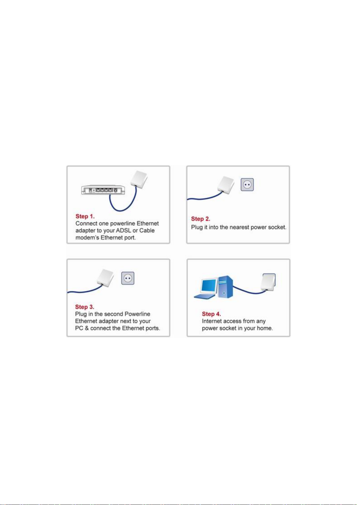
1.1 Simple step to install Powerline Networking
2
Page 5
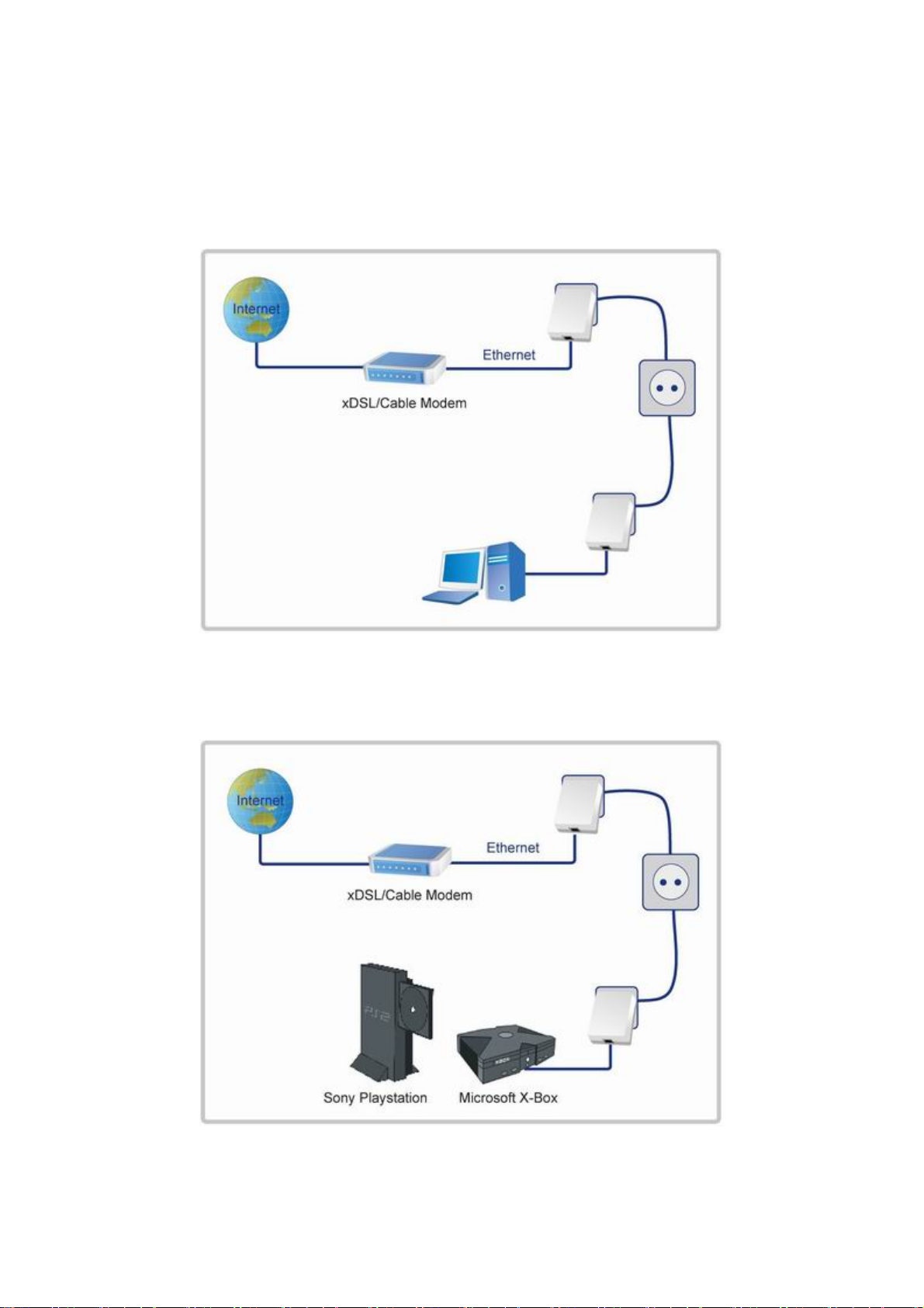
1.2 Application Block Diagram
1.2.1 Internet ADSL with one computer via power outlet
1.2.2 Online game via power outlet
3
Page 6
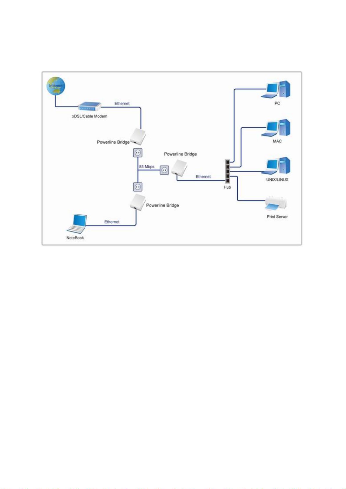
1.2.3 Internet ADSL and Home Networking via power outlet
4
Page 7

1.3 Benefits
‧Data transfers at up to 85 Mbps over the household power circuit
‧Ranges of 200 meters
‧No need new wires for Home networking
‧Deliver the benefits of Ethernet without the wiring expense
‧Send even large files between PCs without long waits
‧High-speed Internet and DVD-quality video streaming
‧Fully compliant with IEEE 802.3, IEEE 802.3u
‧Privacy through DES encryption
1.4 Features
‧Be cost competitive
‧Use the home's existing powerline
‧Easy to install
‧Throughout the whole house, just use your power circuit to access the Internet or
PC network
‧Orthogonal Frequency Division Multiplexing for high data reliability in noisy media
conditions
‧Up to 85Mbps data rate on powerline
‧56-bits DES link encryption for security
‧3 LEDs indicate status
1.5 Package Contents
‧HP-8501
‧CD with Multi-language QIG and Utility
‧Quick Installation Guide
‧Category 5 cable
1.6 System Requirements
‧Ethernet device
‧AC power outlet
‧Windows system for encryption setup
5
Page 8
2. Powerline Networking Utility
Note. The HP-8501 can auto detect the other powerline bridges which plug in the same
power circuit, you don’t need to use this powerline utility except you want to encryption all the
powerline devices as the same group or you can not access the other computers.
Introduction of Configuration Utility
The Configuration Utility for Windows OS (Support Vista 32/64 edition) enables the
user to find Powerline Ethernet devices on the Powerline network; measures data
rate performance, ensures privacy, performs diagnostics and secures Powerline
networks.
2.1 Configuration Utility Setup
2.1.1 Installation of the Utility
Please verify that no other Powerline Management Utilities are installed before
installing this product. If other utilities are installed, uninstall them and restart before
installing this software.
To install, insert the Windows OS Configuration Utility Setup utility CD-ROM into the
computer's CD-ROM drive. The Setup utility shall run automatically . Alternatively this
can also be done manually by double clicking the setup.exe file on the CD. The CD
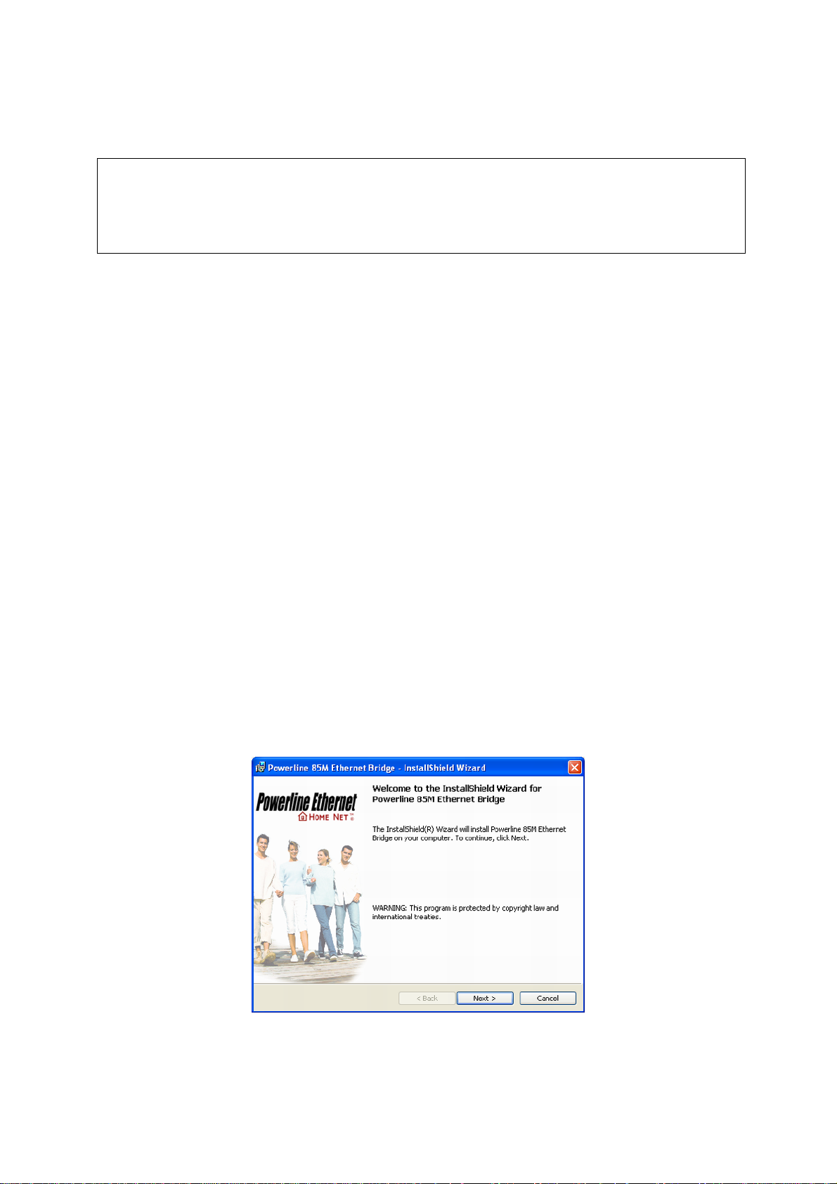
will launch an installation utility similar to the one shown in Figure 1.
This Utility is designed for Powerline 14M and 85M Ethernet bridges. Click the
Next button to continue.
Figure 1: Install Shield Screen
6
Page 9

2.2 Windows Configuration Utility
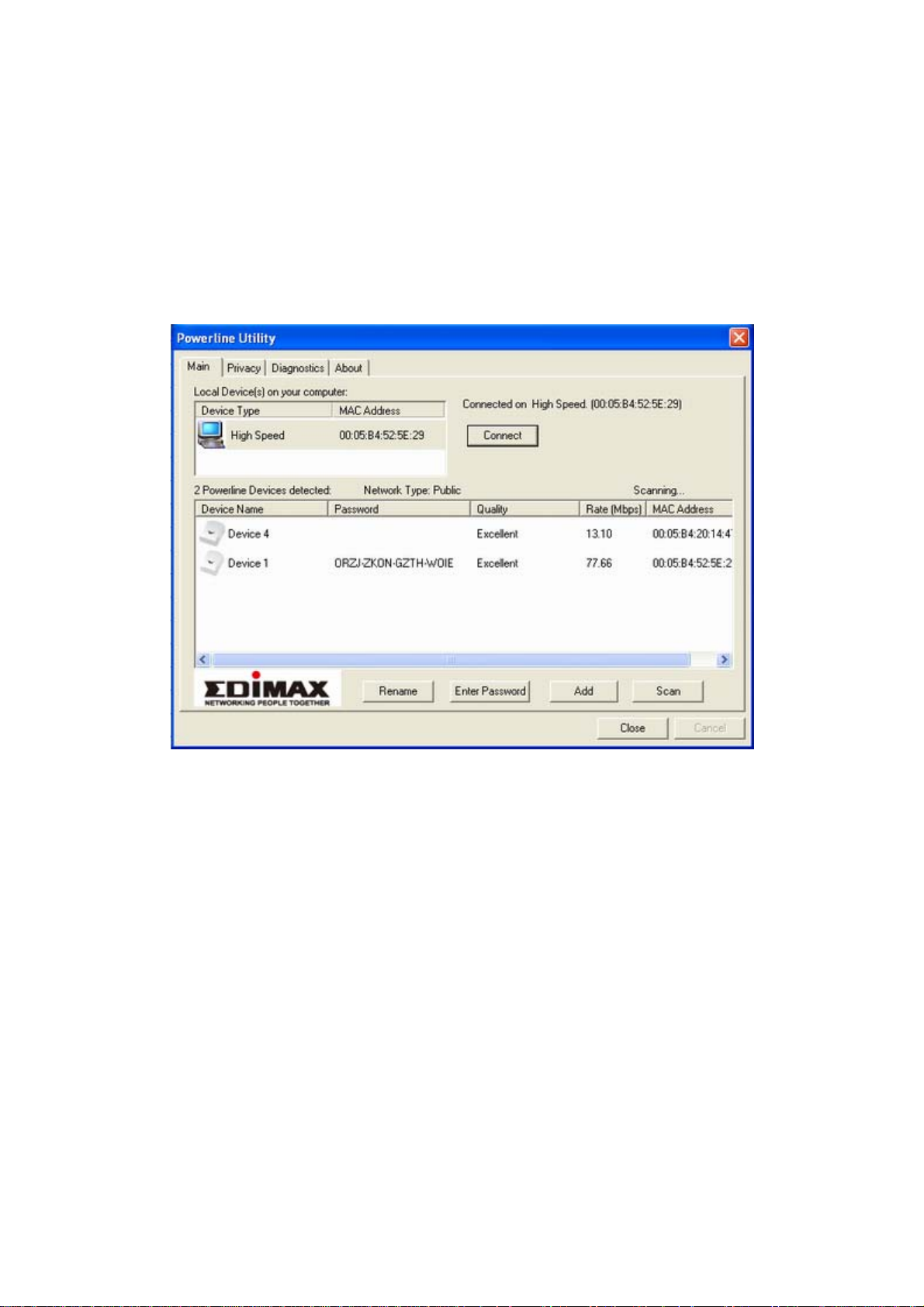
In order to run the utility, double-click the utility icon. Figure 2 shows the main screen
of the configuration utility.
This screen shot shows a Powerline Ethernet device connected as a local device and
other Powerline Ethernet devices as remote devices.
Figure 2: Main Screen with High-Speed Powerline Ethernet device Local
7
Page 10

2.3 User Interface
2.3.1 Main Screen
The Main screen essentially provides a list of all Powerline Ethernet devices logically
connected to the computer where the utility is running.
The top panel shows all local Powerline Ethernet devices found connected to the
computer's NIC (Network Interface Card). In most cases, only one device will be
seen. In situations where there are more than one device connected, such as a USB
and also an Ethernet device, the user may click to select the one to manage through
and then click the Connect button to its right. The status area above the button
indicates that your PC is connected to that same device. Once connected to the
chosen local device, the utility will automatically scan the
powerline periodically for any other Powerline Ethernet devices. If no local Powerline
Ethernet devices are discovered, the status area above the connect button will
indicate that accordingly.
Figure 3 illustrates the presence of two local devices in the computer.
Figure 3: Multiple Local Device Connection
8
Page 11

The lower panel displays all the Powerline Ethernet devices, discovered on the
current logical network (remote devices). Displayed immediately above this panel is
the number of remote devices found, the type of logical network (Public or Private),
and a message area that reports connectivity
and scan status. The following information is displayed for each of the devices
discovered that appear in the lower panel:
Device Name column shows the default device name, which may be user re-defined.
A user may change the name by clicking on the name and editing in-place, or by
using the rename button. An icon is optionally shown with the name. A distinction in
icons is made between low-speed and high-speed devices (14Mbps and 85Mbps).
By default, the icon is displayed with the name.
MAC Address column shows the device's MAC address.
Password column shows the user-supplied device password (initially left blank).
A user may enter the password by using the Set Password button.
To s e t t h e Password of the device (required when creating a private network), first
select the device by clicking on its name in the lower panel and then click on the
Enter Password button.
A dialog box will appear as shown in Figure 4 to type the password. The selected
device name is shown above the field for entering the password. Hit OK after
entering the new password. A confirmation box will appear if the password was
entered correctly.
If a device is not found, the user will be notified and suggestions to resolve common
problems will be presented.
9
Page 12

Figure 4: Set Device Password
The Add button is used to add a remote device to your network that is not on the
displayed list in the lower panel, for example, a device currently on another logical
network. Users are advised to locate the passwords for all devices they wish to
manage and add them to the local logical network by clicking on the Add button.
A dialog box will appear as seen below. The dialog box allows the user to enter both
a device name and the password.
A confirmation box will appear if the password was entered correctly and if the device
was found.
If a device is not found, the user will be notified and suggestions to resolve common
problems will be presented.
10
Page 13

Figure 5: Add Remote Device
Note: The device must be present on the power line (plugged in) in order for the
password to be confirmed and added to the network. If the device could not be
located, a warning message will be shown.
11
Page 14
The Scan button is used to perform an immediate search of the Powerline Ethernet
devices connected to the computer.
By default the utility automatically scans every few seconds and updates the display.
A typical screen after naming and supplying passwords might appear as in Figure 6.
Figure 6: Main Screen of the Configuration Utility
12
Page 15

2.3.2 Privacy Screen
The Privacy dialog screen provides a means for managing the local network and
providing additional security.
All Powerline Ethernet devices are shipped using a default logical network (network
name), which is normally “HomePlug”.
The Privacy dialog screen allows user to make the network private by changing the
network name (network password) of devices.
The user can always reset a Powerline Ethernet network to the universal one (public)
by entering “HomePlug” as the network name or by clicking on the Use Default
button.
Note: Changing the network name to any other name other than HomePlug will show
the network type on the main screen as Private.
Figure 7: Privacy Screen
13
Page 16

The Set Local Device Only button is used to change the network name (network
password) for the local device only.
After doing this, all the devices seen on the Main panel prior to this will no longer be
able to communicate or respond to the computer, as they will be on a different logical
network. Devices previously set up with the same logical network (same network
name) will appear in the device list afterward selecting this option.
The Set All Devices button is used to change the logical network of all devices that
appear on the Main panel.
The user must have entered the device's Password in order to set it to the new
logical network. A notification message will appear to report the success of this
operation.
14
Page 17

2.4 Diagnostics Screen
The Diagnostics screen shows system information and a history of all devices seen.
The appearance is shown in Figure 8.
The upper panel shows technical data concerning software and hardware on the
host computer used to communicate over Powerline Ethernet Network.
It shall include the following:
‧Operating System Type/Version
‧Host Network Name
‧User Name
‧MAC Address of all NICs (network interface card)
‧Identify versions of all Driver DLLs and Libraries used (NDIS) and optionally
‧Powerline Ethernet device chipset manufacturer name (85Mbps version Only)
‧MAC Firmware Version (85Mbps version Only)
‧Vendor name
15
Page 18

Figure 8: Diagnostics Screen
The lower panel contains a history of all remote devices seen on the computer, over
time. Devices are shown here regardless of whether or not they are on the same
logical network. Devices that are active on the current logical network will show a
transfer rate in the Rate column; devices on other networks, or devices that may no
longer exist are shown with an “?” in the Rate column.
The following remote device information is available from the diagnostics screen:
‧Adapter Alias Name
‧Adapter MAC Address
‧Adapter Password
‧Adapter Last known rate
‧Adapter Last Known Network
‧HomePlug chipset manufacturer name
‧Date device last scanned
‧MAC Firmware Version (85Mbps version Only)
16
Page 19

The diagnostics information displayed may be saved to a text file for later emailing to
technical support of a manufacturer or printed for reference during a technical
support call. Devices no longer part of the network can be deleted using the delete
button.
2.4.1 About Screen
The screen shows the software release date.
Figure 9: About dialog screen
2.4.2 Preferences
The lower part of the panel may display options for user preferences (such as turning
the auto-scan feature on or off) as shown Figure 9 above.
17
Page 20

Declaration of Conformity
The following
Equipment : Powerline Ethernet 85
Report No. : S940140
is herewith confirmed to comply with the requirements set out in the Council Directive on
the harmonization of the Laws of the Member States relating to electrical equipment
designed for use within certain voltage limits(73/23/EEC).
For the evaluation of above mentioned Directives, the following standards were applied:
IEC 60950-1: 2001
EN 60950-1: 2001
Declaration of Conformity
The following
Equipment : Powerline Ethernet 85
Report No. : E940708
is herewith confirmed to comply with the requirements of its Harmonised Standards for
CE Marking which have been set out in the Council Directive, and published as below:
1) The R&TTE Directive 1999/5/EC
2) The EMC Directives of 89/336/EEC, 92/31/EEC and 93/68/EEC;
For the evaluation of above mentioned Harmonised Standards, the following technical and
test standards were applied:
1) EN 55022: 1998+A1 : 2001+A2: 2003 Class A
2) EN 61000-3-2 : 2000
3) EN 61000-3-3 : 1995+A1: 2001
4) EN 55024 : 1998+A1 : 2001+A2: 2003
EN 61000-4-2 : 1995+A1: 1998+A2: 2001
EN 61000-4-3 : 2002+A1: 2002
EN 61000-4-4 : 1995+A2: 2001
EN 61000-4-5 : 1995+A1: 2001
18
Page 21

EN 61000-4-6 : 1996+A1: 2001
EN 61000-4-8 : 1993+A1: 2001
EN 61000-4-11 : 1994+A1: 2001
Testing Laboratory:
PEP TECHNOLOGIES LTD.
12FL-3, NO.27-1, LANE 169, KANG NING ST., HSI CHIH CITY, TAIPEI HSIEN, TAIWAN, R.O.C.
19
Page 22

20
 Loading...