

Page 1

1
HP-5101Wn
User Manual
03-2013 / v1.0
Page 2

2
COPYRIGHT
Copyright Edimax Technology Co., Ltd. all rights reserved. No part of this publication
may be reproduced, transmitted, transcribed, stored in a retrieval system, or translated
into any language or computer language, in any form or by any means, electronic,
mechanical, magnetic, optical, chemical, manual or otherwise, without the prior written
permission from Edimax Technology Co., Ltd.
Edimax Technology Co., Ltd. makes no representations or warranties, either expressed or
implied, with respect to the contents hereof and specifically disclaims any warranties,
merchantability, or fitness for any particular purpose. Any software described in this
manual is sold or licensed as is. Should the programs prove defective following their
purchase, the buyer (and not this company, its distributor, or its dealer) assumes the
entire cost of all necessary servicing, repair, and any incidental or consequential damages
resulting from any defect in the software. Edimax Technology Co., Ltd. reserves the right
to revise this publication and to make changes from time to time in the contents hereof
without the obligation to notify any person of such revision or changes.
The product you have purchased and the setup screen may appear slightly different from
those shown in this QIG. For more information about this product, please refer to the
user manual on the CD-ROM. The software and specifications are subject to change
without notice. Please visit our website www.edimax.com for updates. All brand and
product names mentioned in this manual are trademarks and/or registered trademarks of
their respective holders.
Edimax Technology Co., Ltd.
Add: No. 3, Wu-Chuan 3rd Rd., Wu-Ku Industrial Park, New Taipei City, Taiwan
Tel: +886-2-77396888
Email: sales@edimax.com.tw
Notice According to GNU General Public License Version 2
This product includes software that is subject to the GNU General Public License version
2. The program is free software and distributed without any warranty of the author. We
offer, valid for at least three years, to give you, for a charge no more than the costs of
physically performing source distribution, a complete machine-readable copy of the
corresponding source code.
Page 3

3
CONTENTS
I. PRODUCT INFORMATION ......................................................................................... 5
I-1. Package Contents ..................................................................................................................... 5
I-2. Hardware ................................................................................................................................. 5
I-3. LED Status ................................................................................................................................ 6
I-4. Safety Information ................................................................................................................... 7
I-5. System Requirements For Powerline Utility Software ............................................................. 7
II. CREATING A POWERLINE NETWORK ........................................................................ 8
II-1. Hardware Installation .......................................................................................................... 8
II-2. iQ Setup ............................................................................................................................. 10
II-3. WPS Setup .............................................................................................................................. 15
II-4. Connecting to your HP-5101Wn ........................................................................................ 16
II-5. Leaving a Powerline Network ............................................................................................ 18
II-6. Resetting the Wireless Extender........................................................................................ 18
III. BROWSER BASED CONFIGURATION INTERFACE ...................................................... 19
III-1. Home.................................................................................................................................... 21
III-2. iQ Setup ............................................................................................................................... 23
III-3. Basic Setting ......................................................................................................................... 24
III-3-1. Security ............................................................................................................................ 26
III-3-1-1. Disable ......................................................................................................................... 27
III-3-1-1-1. 802.1x Authentication ................................................................................................. 27
III-3-1-2. WEP .................................................................................................................................. 28
III-3-1-2. WPA Pre-shared Key......................................................................................................... 29
III-3-1-3. WPA Radius ...................................................................................................................... 30
III-4. WPS Setting .......................................................................................................................... 32
III-5. Wireless Advanced ............................................................................................................... 34
III-5-1. MAC Filtering ............................................................................................................... 36
III-6. System Utility ............................................................................................................... 38
III-6-1. Time Setting ................................................................................................................. 41
III-6-2. Scheduling Setting ........................................................................................................... 42
II-7. Configuration Tool ................................................................................................................ 45
III-7-1. Diagnosis .......................................................................................................................... 47
III-7-2. Firmware Upgrade ........................................................................................................... 48
III-7-3. Reboot .............................................................................................................................. 49
IV. POWERLINE UTILITY SOFTWARE ............................................................................ 50
IV-1. Installation ........................................................................................................................... 50
IV-1.1 Win 8 ................................................................................................................................ 50
IV-1.2 Win XP/Vista / 7 ............................................................................................................... 59
IV-2. Using the Utility Software ..................................................................................................... 65
IV-2-1. Main Tab ............................................................................................................................ 65
IV-2-2. Diagnostics Tab .................................................................................................................. 66
IV-2-3. About Tab .......................................................................................................................... 67
V. APPENDIX .............................................................................................................. 68
Page 4

4
V-1. Configuring your IP address ................................................................................................. 68
V-1-1. How to Configure Your Computer to Use a Dynamic IP Address ..................................... 68
V-1-1-1. Windows XP ................................................................................................................. 69
V-1-1-2. Windows Vista ............................................................................................................. 70
V-1-1-3. Windows 7 ................................................................................................................... 72
IV-1-1-4. Windows 8 ................................................................................................................... 74
V-1-1-5. Mac OS ......................................................................................................................... 78
V-1-2. How to Modify the IP Address of Your PC or Macintosh ................................................. 80
V-1-2-1. Windows XP ................................................................................................................. 80
V-1-2-2. Windows Vista ............................................................................................................. 81
V-1-2-3. Windows 7 ................................................................................................................... 82
V-1-2-4. Windows 8 ................................................................................................................... 84
V-1-2-5. Mac OS ......................................................................................................................... 88
V-1-3. How to Find Your Network Security Key ............................................................................ 90
V-1-3-1. Windows 7 & Windows Vista ...................................................................................... 90
V-1-3-2. Windows 8 ................................................................................................................... 92
V-1-3-3. Mac .............................................................................................................................. 95
V-1-4. How to Find Your Router’s IP Address ............................................................................... 98
V-1-4-1. Windows XP, Vista & 7 ................................................................................................. 98
V-1-4-2. Windows 8 ................................................................................................................... 99
V-1-4-3. Mac ............................................................................................................................101
V-2. Troubleshooting ...............................................................................................................103
V-3. Glossary ...........................................................................................................................105
Page 5
5
I. PRODUCT INFORMATION
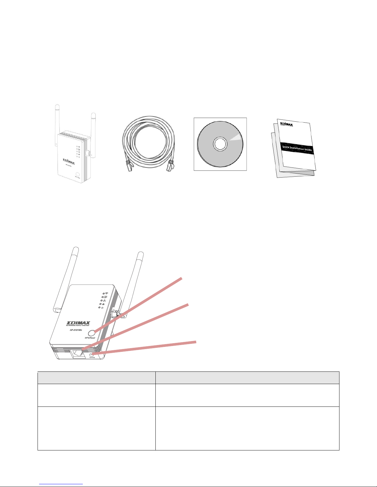
Before you start using this product, please check if there is anything missing in
the package, and contact your dealer to claim the missing items(s):
I-1. Package Contents
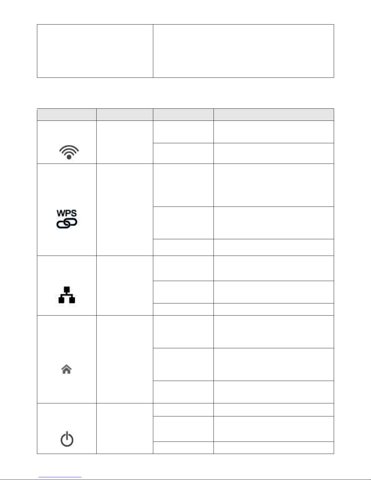
I-2. Hardware
Item
Description
Ethernet Port
Connects HP-5101Wn to a computer or other
network device via Ethernet cable.
WPS/Reset Button
Resets the HP-5101Wn to factory default
settings or starts the WPS function.
Reset: Press for over 10 seconds.
WPS: Press for 2–5 seconds.
HP-5101Wn
Ethernet
CD-ROM
Quick Installation Guide
WPS/Reset Button
Ethernet Port
Group Button
Page 6
6
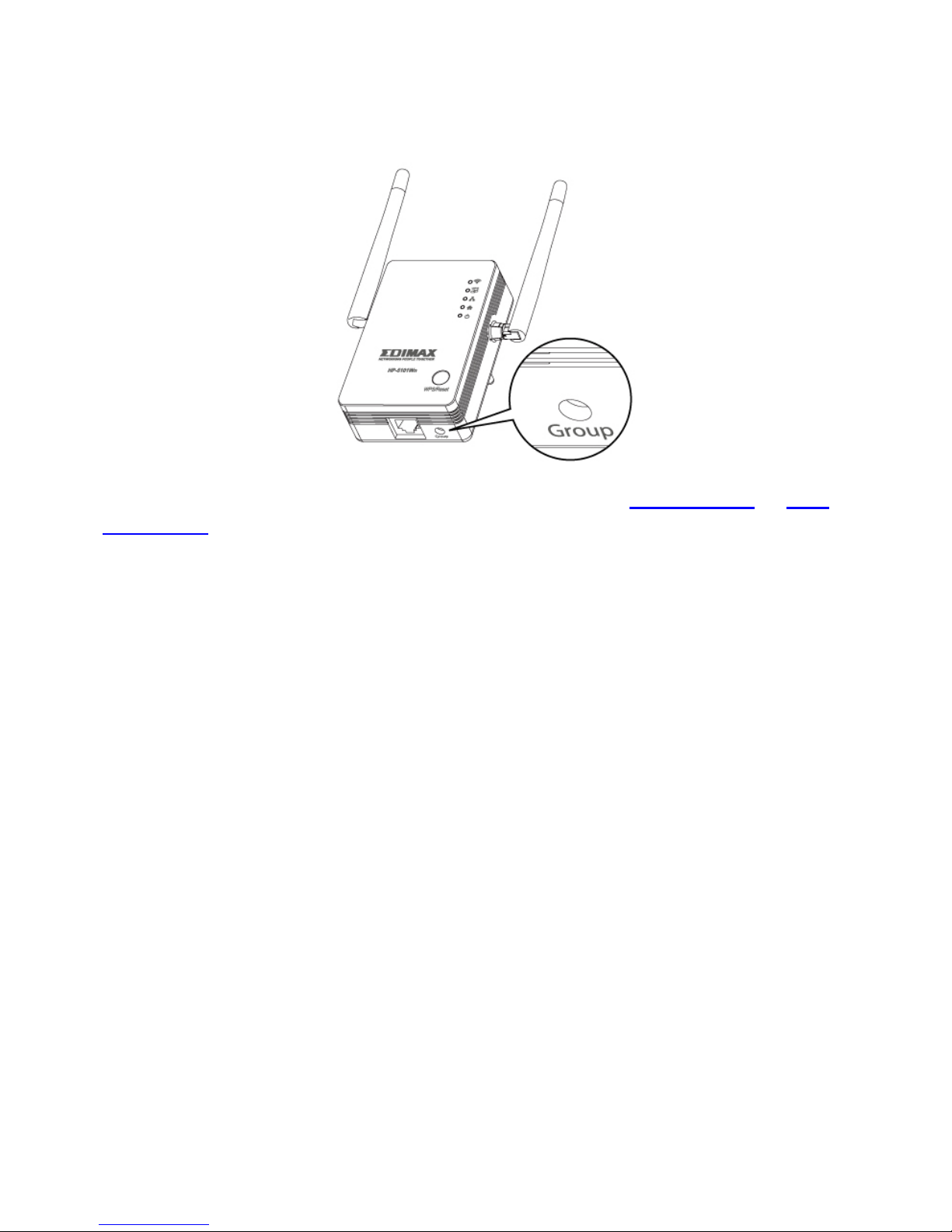
Group Button
Groups the HP-5101Wn with other Powerline
devices to establish an encrypted Powerline
network. Press for less than 3 seconds to
join/establish a network, and 5–8 seconds to
leave a Powerline network.
I-3. LED Status
LED
Color
LED Status
Description
WLAN
Green
Flashing
Wireless activity (transmitting
or receiving data).
Off
No wireless activity.
WPS
Green
On
WPS connection established
(LED remains on for one
minute after the connection is
made).
Flashing
WPS in progress (waiting for
another WPS device’s
connection).
Off
No WPS in progress.
LAN
Green
On
LAN port connected.
Flashing
LAN activity (transferring or
receiving data).
Off
LAN port not connected.
PLC
Green &
Yellow
Flashing
Green with
slow yellow
flashing
Detecting Powerline
connection.
Green with
rapid yellow
flashing
Powerline activity (transferring
or receiving data).
Off
No Powerline connection
detected.
Power
Green
On
HP-5101Wn is on.
Flashing every
15 seconds
The HP-5101Wn is in
power-saving mode.
Off
HP-5101Wn is off.
Page 7

7
I-4. Safety Information
In order to ensure the safe operation of the device and its users, please read
and act in accordance with the following safety instructions.
1. The wireless extender is designed for indoor use only; do not place the
wireless extender outdoors.
2. Do not place the wireless extender in or near hot/humid places, such as a
kitchen or bathroom.
3. Do not pull any connected cable with force; carefully disconnect it from the
wireless extender.
5. The device contains small parts which are a danger to small children under
3 years old. Please keep the wireless extender out of reach of children.
6. Do not place the wireless extender on paper, cloth, or other flammable
materials. The wireless extender will become hot during use.
7. There are no user-serviceable parts inside the wireless extender. If you
experience problems with the wireless extender, please contact your dealer
of purchase and ask for help.
8. The wireless extender is an electrical device and as such, if it becomes wet
for any reason, do not attempt to touch it without switching the power
supply off. Contact an experienced electrical technician for further help.
9. If you smell burning or see smoke coming from the wireless extender then
unplug the extender immediately, as far as it is safely possible to do so. Call
your dealer of purchase for help.
I-5. System Requirements For Powerline Utility Software
Operating System
Utility supports Windows XP/Vista/7/8
CPU
Intel Pentium III 1.0GHz (or above)
RAM
256MB (or above)
Free Disk Space
100MB (or above)
Network Interface
Ethernet port (100Mbps or above) and an Ethernet
cable
Page 8
8
II. CREATING A POWERLINE NETWORK
A minimum of two Powerline devices are required to establish
a Powerline network.
For best performance, plug Powerline adapters directly into
standard wall sockets. Avoid using multi-socket adapters.
It may be convenient to install and configure your Powerline
adapters in the same room, and then relocate the HP-5101Wn
to its preferred location after setup is complete.
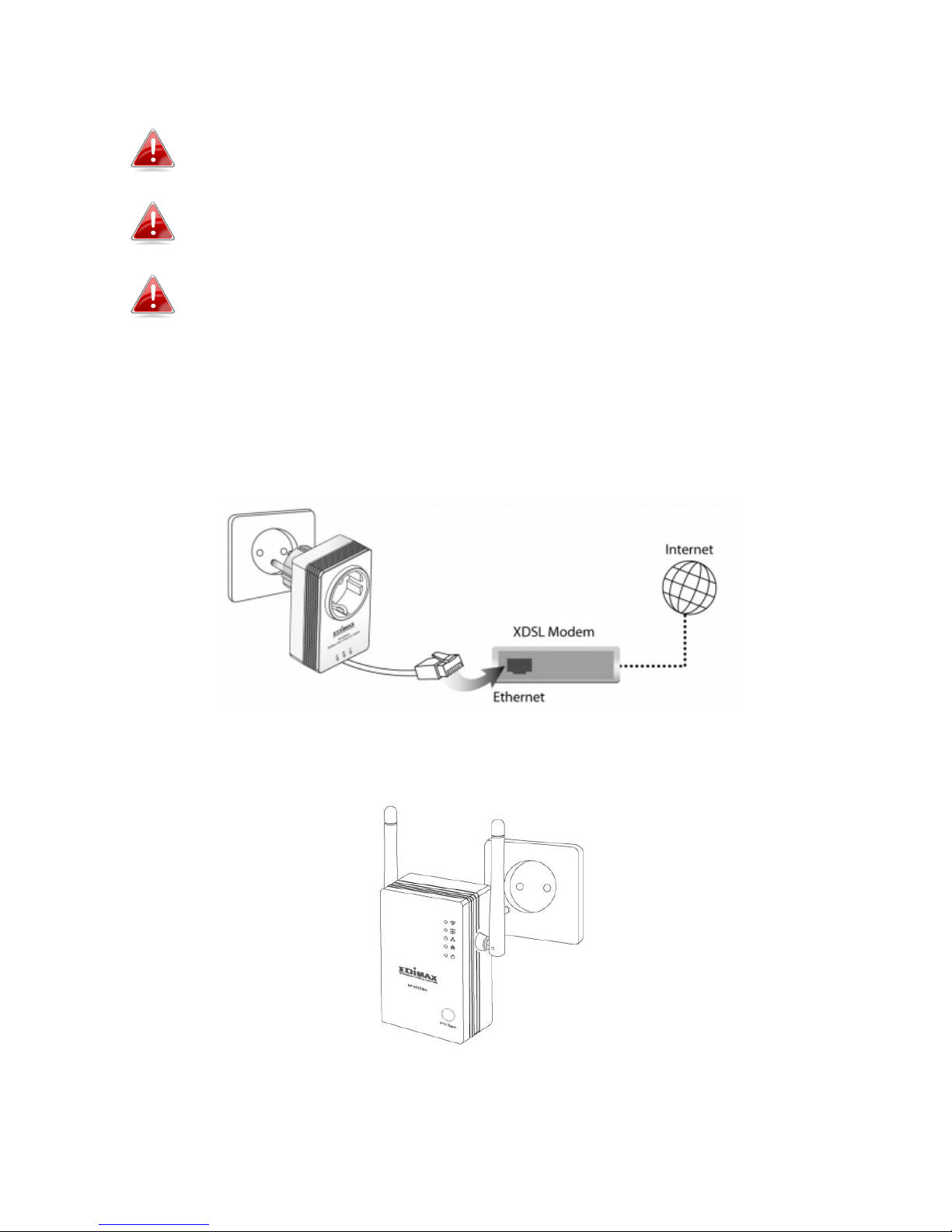
II-1. Hardware Installation
1. Connect one Powerline adapter to your router via Ethernet cable and plug
it into a power socket. The power and LAN LEDs should display on.
2. Plug another Powerline adapter (HP-5101Wn) into a power socket, and
confirm the power LED is on.
3. The PLC LED on both Powerline adapters should indicate first that they are
detecting a Powerline connection, and then that a Powerline connection is
established. See LED Status for HP-5101Wn LEDs.
Page 9
9
4. Press the “Group” button button on each Powerline adapter for less than 3
seconds, within 2 minutes of each other. The adapters will automatically
group together and generate an encrypted network.
You can now setup the HP-5101Wn’s Wi-Fi using either II-2. iQ Setup or II-3.
WPS Setup.
Page 10
10
II-2. iQ Setup
1. Use a Wi-Fi device (e.g. computer, tablet, smartphone) to search for a Wi-Fi
network with the SSID “Edimax.Setup” and connect to it.
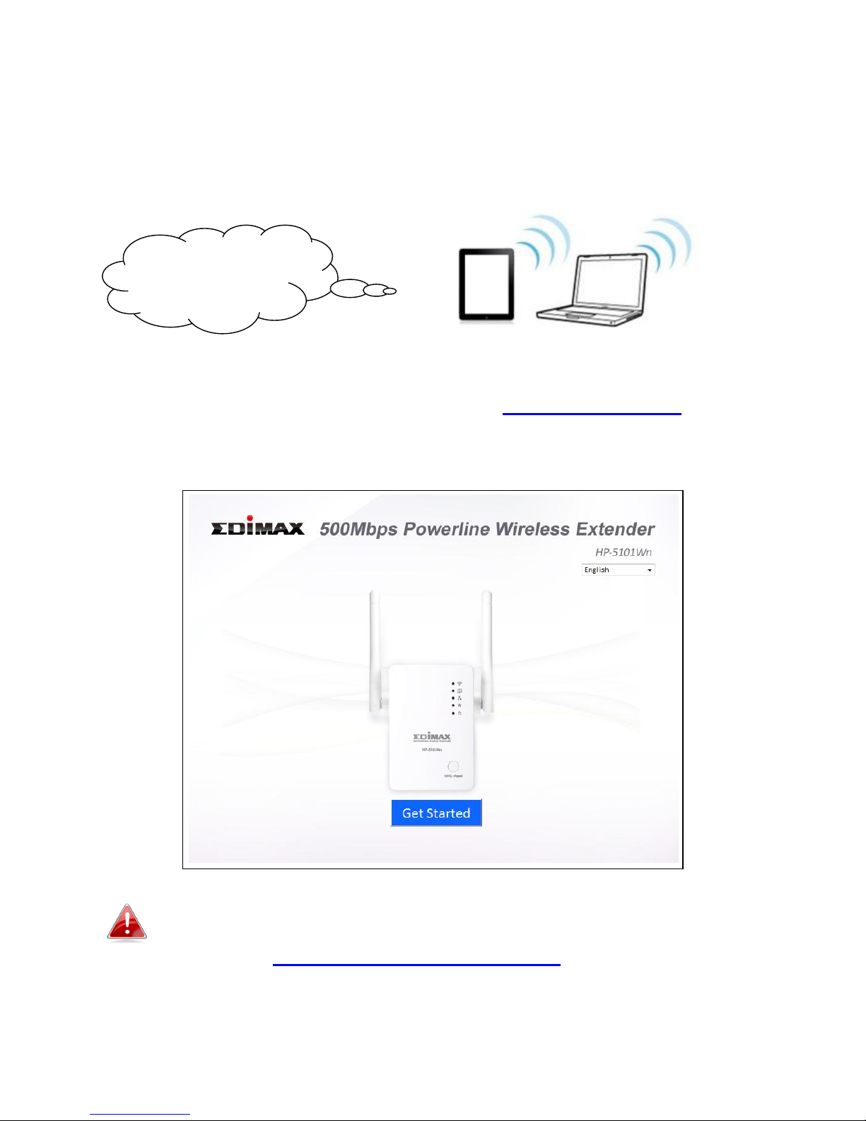
2. Open a web browser and if you do not automatically arrive at the “Get
Started” screen shown below, enter the URL http://edimax.setup. Select
your language from the drop down menu and click “Get Started” to begin
the setup process.
If you cannot access http://edimax.setup, please make sure
your computer is set to use a dynamic IP address. If you are
unsure, see V-1. Configuring your IP address.
SSID:
Edimax.Setup
Page 11
11
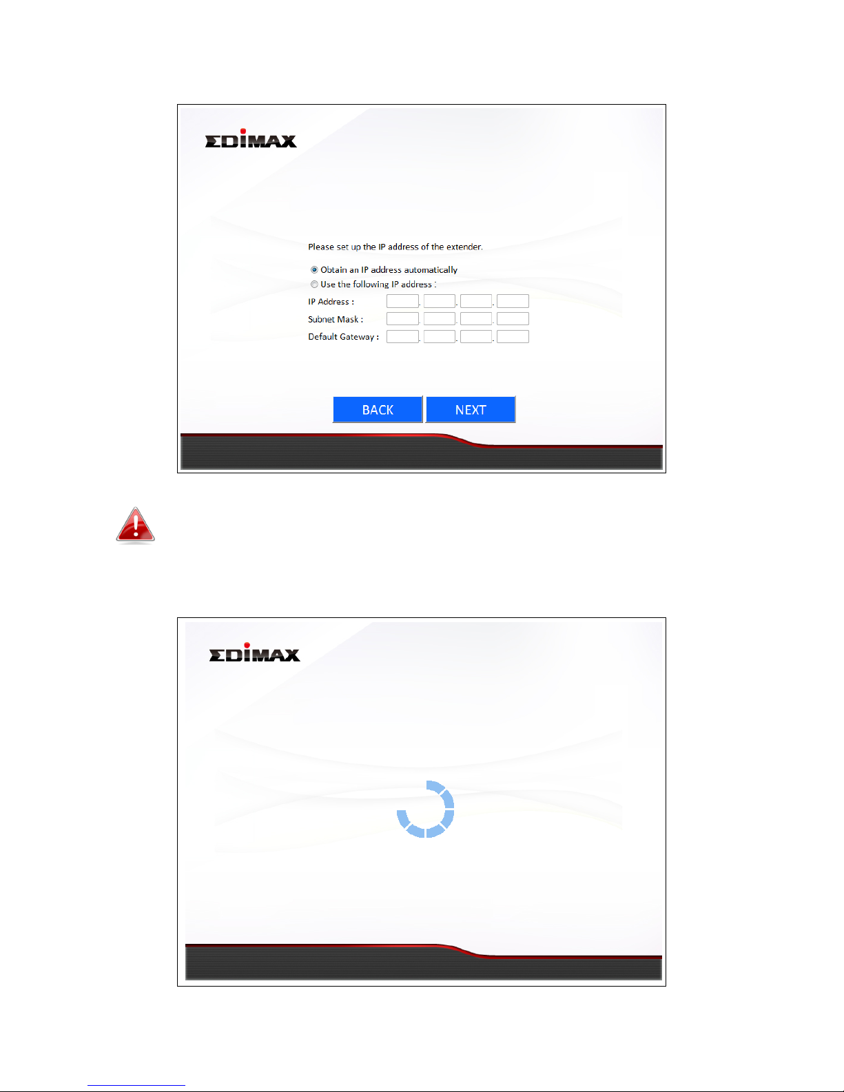
3. Select “Obtain an IP address automatically” and then click “NEXT”.
Advanced users who need to specify an IP address for the
HP-5101Wn, select “Use the following IP address”.
4. Please wait a moment.
Page 12

12
5. Please enter a “MAIN ESSID” – this is a name to identify the HP-5101Wn’s
Wi-Fi network, which you will connect to from your wireless device. Then
select a channel number (“Auto” is recommended) and enter a “Wi-Fi
Security Password” between 8–64 characters, which is the password used
to connect to the HP-5101Wn’s Wi-Fi network. Click “Next” to continue.
Please do not forget your Wi-Fi password. If you do not wish
to use a Wi-Fi password, check the box labeled “I don’t want
to set up the Wi-Fi password”.
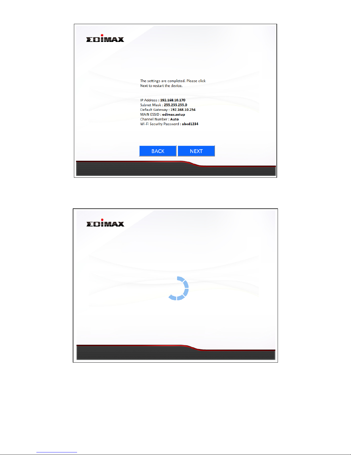
6. A summary of your HP-5101Wn’s Wi-Fi settings will be displayed, as shown
below. Click “NEXT” to continue and restart your HP-5101Wn.
Page 13
13
7. Please wait while the HP-5101Wn restarts.
8. When the HP-5101Wn has restarted, the following “Congratulations”
screen will be displayed, indicating that wireless setup is complete. Your
HP-5101Wn’s Wi-Fi should now be active and ready for use. If you need,
you can relocate the HP-5101Wn to any power socket within 300m without
additional configuration.
Page 14

14
Refer to II-4. Connecting to your HP-5101Wn for help with connecting a Wi-Fi
device to the extender’s Wi-Fi.
Page 15
15
II-3. WPS Setup
If your wireless router/access point supports WPS (Wi-Fi Protected Setup)
then you can use this method to set up your HP-5101Wn’s Wi-Fi network.
WPS is an alternative to II-2. iQ Setup. The HP-5101Wn’s Wi-Fi settings
(including SSID) will be the same as your existing router/access point.
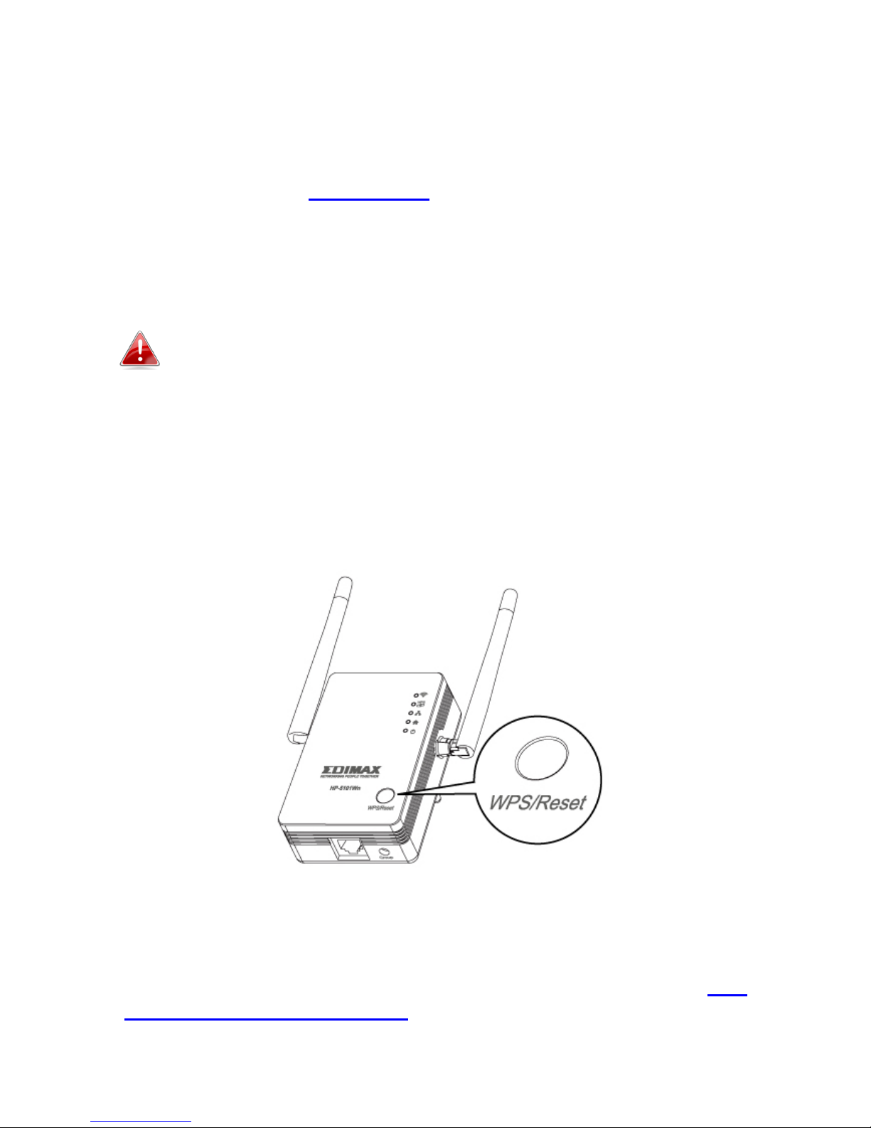
1. Press the WPS button (often the WPS/Reset button) on your router/access
point to activate WPS.
Please check the instructions for your wireless router/access
point for how long you need to hold down its WPS button to
activate WPS. Take care not to hold the WPS button for too
long – this may result in inadvertently resetting the extender
or router/access point.
2. Within two minutes, press and hold the WPS button for 2–5 seconds on
the HP-5101Wn to activate its WPS. The HP-5101Wn’s WPS LED should
flash to indicate a WPS connection is in progress.
3. The devices will establish a connection. The HP-5101Wn’s WPS LED should
display on to indicate a successful connection. You can now connect to the
HP-5101Wn’s wireless network with a Wi-Fi device, as described in II-4.
Connecting to your HP-5101Wn.
Page 16
16
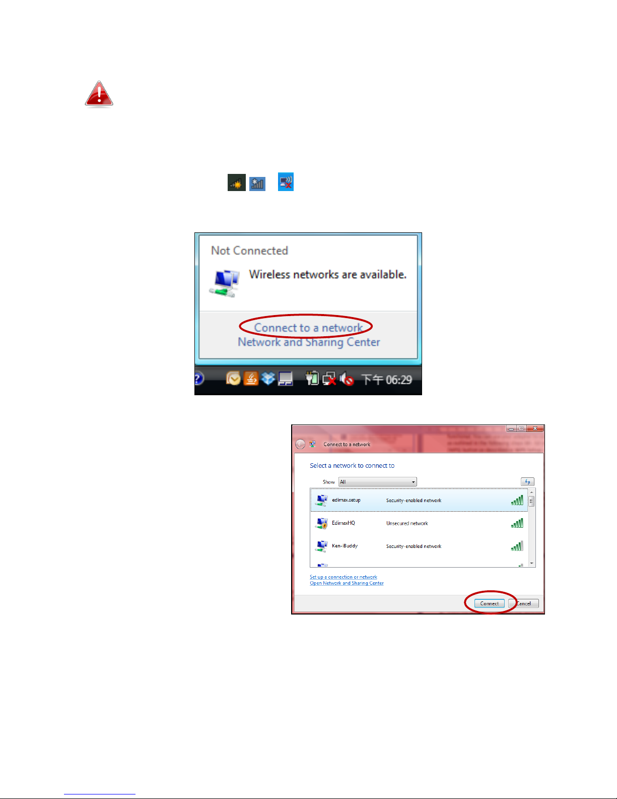
II-4. Connecting to your HP-5101Wn
The following steps 9-11 are an example of how to connect to
a Wi-Fi network using Windows Vista. If you are using a
different version of Windows, the process may vary slightly –
please connect to a Wi-Fi network in the usual manner for
operating system.
1. Click the network icon ( , or ) in the system tray and select “Connect
to a network”.
2. Search for the SSID of your
Wi-Fi network, click it and then
click “Connect”. If you set a
password for your network, you
will then be prompted to enter
it.
Page 17

17
3. After correctly entering
your password, you will be
successfully connected to
your Wi-Fi network.
4. You can also use the Ethernet port on the underside of the HP-5101Wn to
connect a computer or other device via Ethernet cable.
Page 18

18
II-5. Leaving a Powerline Network
Press the Group/Reset button on the wireless extender for 5–8 seconds to
leave a Powerline network that the extender is connected to. The extender
will be disconnected/ungrouped from its network and ready to reconnect to
any Powerline network.
II-6. Resetting the Wireless Extender
If you experience a problem with your HP-5101Wn you can reset the device
back to its factory default settings. This resets all settings back to default.
Press and hold the WPS/Reset button for at least 10 seconds. The HP-5101Wn
will re-initialize and the power LED ( ) will display on when the extender is
ready (see LED Status).
Page 19
19
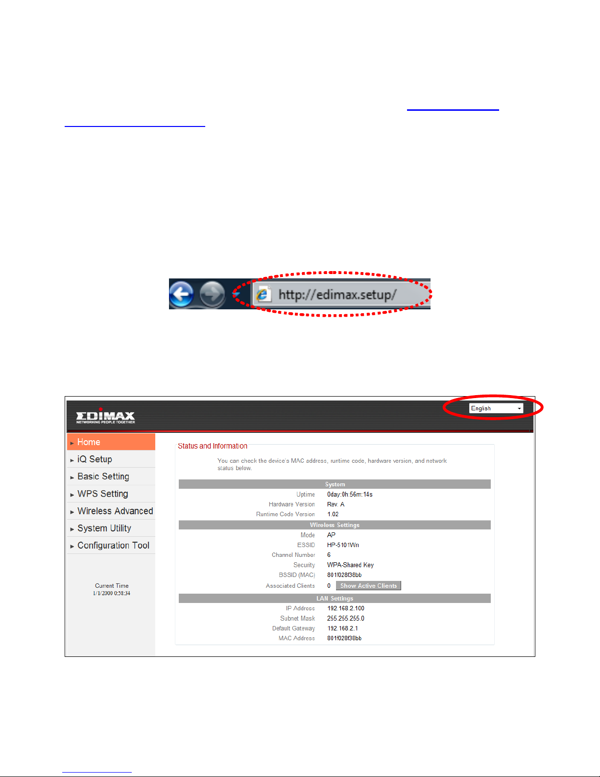
III. BROWSER BASED CONFIGURATION INTERFACE
Once you have setup the wireless extender as detailed in II. CREATING A
POWERLINE NETWORK or the included QIG, you can further configure the
settings of the wireless extender or run iQ Setup again using the browser
based configuration interface.
To access the browser based configuration interface, enter
http://edimax.setup into the URL bar of a web browser on a computer which
is connected to the extender’s Wi-Fi network. You will be prompted for a
username and password. The default username is “admin” and the default
password is “1234”.
You will arrive the at Home page, use the menu on the left side of the screen
to navigate. You can also change the language using the drop down menu in
the top right corner.
Page 20

20
- III-1. Home
- III-2. iQ Setup
- III-3. Basic Setting
- III-4. WPS Setting
- III-5. Wireless Advanced
- III-6. System Utility
- III-7. Configuration Tool
Page 21
21
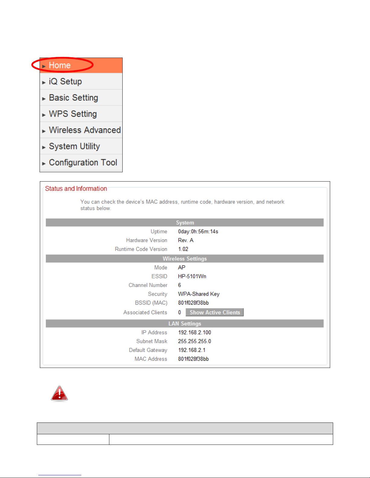
III-1. Home
The Home page shows the basic status and
information of the wireless extender.
The screenshots shown in this manual are examples. The
information you see on your screen will be unique to your
configuration.
System
Uptime
Displays the total passed time since the device was turned
Page 22
22
on.
Hardware Version
Displays the hardware version.
Runtime Code
Version
Displays the current firmware version.
Wireless Configuration
Mode
Displays the current wireless operating mode.
ESSID
Displays the current ESSID (the name used to identify the
wireless extender).
Channel
Number
Displays the current wireless channel number.
Security
Displays the current wireless security/encryption type.
BSSID (MAC)
Displays the device’s MAC address. A MAC address is a
unique, fixed ID for this device which cannot be modified.
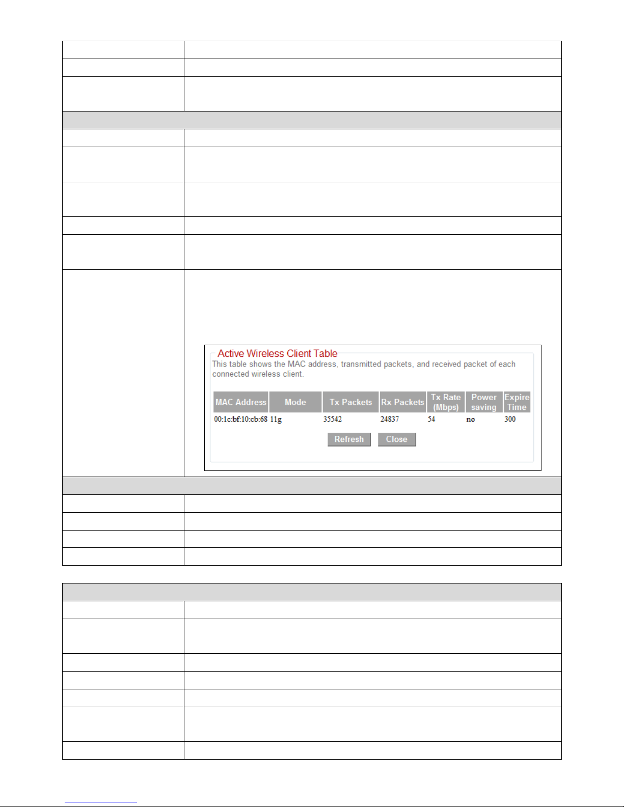
Associated
Clients
Displays the number of clients connected to the wireless
extender. Click the “Show Active Clients” button to display
active clients in a new window (see below for full
description):
LAN Settings
IP Address
Displays the IP address of this device.
Subnet Mask
Displays the subnet mask of the IP address.
Default Gateway
Displays the IP address of the default gateway.
MAC address
Displays the MAC address of the LAN interface.
Active Wireless Client Table
MAC Address
Displays the MAC address of the wireless client.
Mode
Displays the transmission mode (802.11b, 802.11n or
802.11g).
Tx Packet
Tx (transmission) packet counter.
Rx Packet
Rx (received) packet counter.
Tx Rate (Mbps)
Transmission rate is displayed here in Mbps.
Power Saving
“Yes” or “No” is displayed here according to whether
power saving feature is active.
Expired Time (s)
If the wireless client is idle for longer than the expired
Page 23
23
time, the access point will disassociate with it. When the
wireless client becomes active, it will have to re-associate
with the access point.
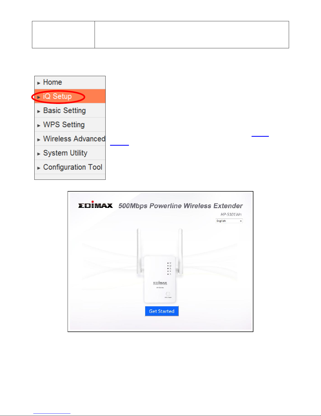
III-2. iQ Setup
To perform iQ Setup again and configure the Wi-Fi
networks which the extender will connect to, select
“iQ Setup”.
You will see the screen below. Please click “Get
Started” to begin iQ Setup and refer back to II. iQ
Setup onwards for further guidance.
Page 24
24
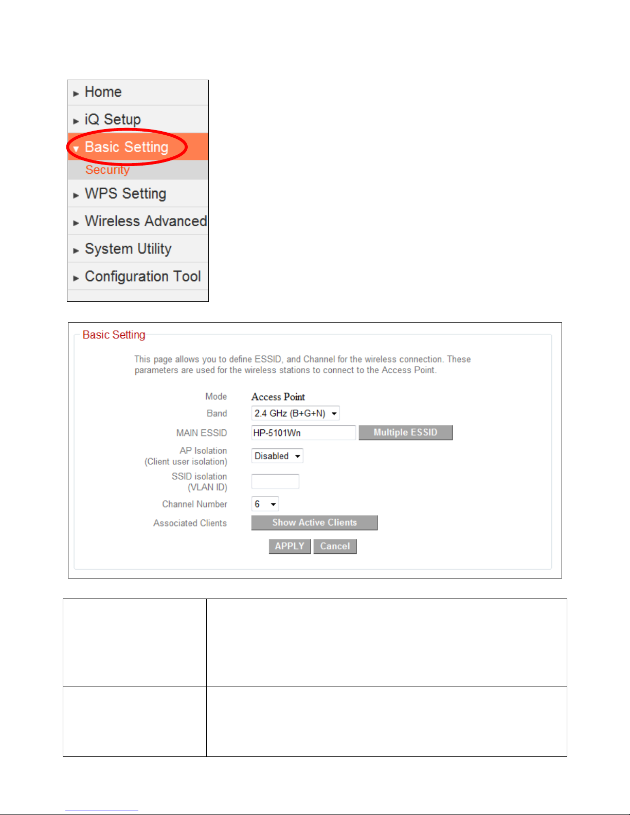
III-3. Basic Setting
The “Basic Setting” page enables you to configure the
ESSID, channel number and other basic parameters of
the wireless extender.
Mode
The extender’s mode cannot be configured – the
default mode is “Access Point”. The device acts as a
wireless access point to a wired Ethernet network.
Wireless clients can connect to the extender and
exchange data with devices connected to the network.
Band
Select the wireless band you wish to use for the access
point. The extender uses the 2.4GHz frequency band –
select which wireless standard or combination of
standards to use. Only wireless clients of the same
Page 25

25
band(s) will be able to connect.
MAIN ESSID
Specify an ESSID (the name used to identify the access
point) of up to up to 32 alphanumerical characters.
Please note that the ESSID is case sensitive.
AP Isolation
When this is set to “Enabled”, wireless clients
connected to this device will be able to access the
Internet, but will not be able to communicate with each
other. This applies to clients connected to the MAIN
ESSID only.
SSID Isolation
When the access point uses multiple SSIDs and this is
set to “Enabled”, then wireless clients connected to the
same SSID will be able to communicate with each
other, but will not be able to communicate with other
wireless clients connected to another of this access
point’s SSIDs. You can input a numeric VLAD ID value
between 1 – 4094 for the MAIN ESSID.
Channel Number
Select a channel number for the wireless extender.
Associated Clients
Click the “Show Active Clients” button and a new
window will appear which displays information about
wireless clients connected to this access point. Click the
“Refresh” button in the new window to refresh the list.
Click “APPLY” to save the changes. The following message will appear:
Click “CONTINUE” to save the changes and continue configuring other settings,
or click “APPLY” to restart the system and make the changes take effect.
Page 26
26
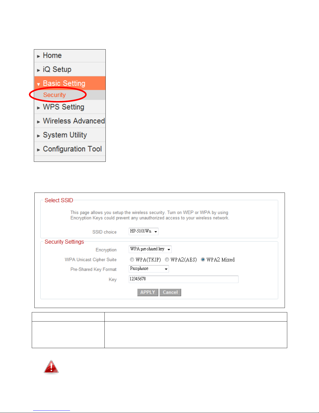
III-3-1. Security
The wireless extender provides a variety of wireless
security options (data encryption) which can be
configured on this page.
It is important to configure security to prevent
intruders from accessing your local network and
causing damage to computers and servers. Use
complicated, hard-to-guess security keys which
include combinations of letters and numbers
and change your security key regularly.
SSID choice
Select which SSID’s security settings to configure.
Encryption
Select an encryption type from the drop down menu
and refer to the appropriate section (following) for
more details.
WPA pre-shared key offers the highest level of security and is
the recommended encryption type.
Page 27
27
III-3-1-1. Disable
Select “Disable” to disable wireless encryption for the network. This is not
recommended - anyone within range can connect to the device’s SSID.
Enable 802.1x
Authentication
Check this box to enable 802.1x user authentication.
See below.
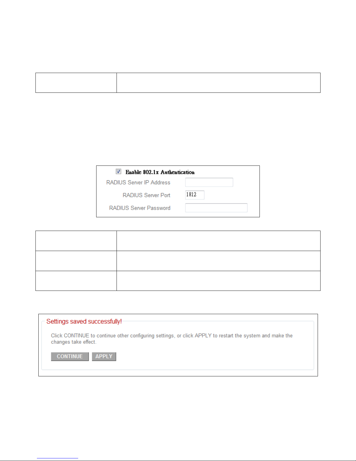
III-3-1-1-1. 802.1x Authentication
If you select “Disable” or “WEP” as your encryption type, you can check the
“Enable 802.1x Authentication” box to enable 802.1x authentication based on
a RADIUS user authentication server.
RADIUS Server IP
Address
Enter the IP address of the RADIUS authentication
server here.
RADIUS Server Port
Enter the port number of the RADIUS authentication
server here. Default value is 1812.
RADIUS Server
Password
Enter the password of the RADIUS authentication
server here.
Click “APPLY” to save the changes. The following message will appear:
Click “CONTINUE” to save the changes and continue configuring other settings,
or click “APPLY” to restart the system and make the changes take effect.
Page 28
28
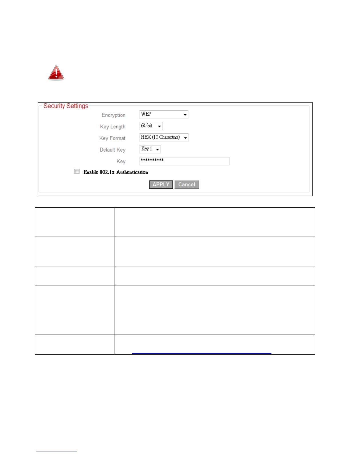
III-3-1-2. WEP
Wired Equivalent Privacy (WEP) is a basic encryption type.
WPA encryption is recommended – though some legacy
wireless devices may only support WEP. WEP supports data
rates up to a maximum 54Mbps.
Key Length
Select “64-bit” or “128-bit” key length. “128-bit” is
safer than “64-bit” but will reduce some data transfer
performance.
Key Format
Select “ASCII” or “Hex” key format. The key length will
also be displayed here - ASCII and Hex keys vary in
length depending on “Key Length” (above)”.
Default Key
The value for “Default Key” is “Key 1” and cannot be
modified.
Encryption Key 1 to
4
Enter WEP key here, the number of characters must be
the same as the number displayed in the “Key Format”
field. For “ASCII” key format, you can use any
alphanumerical characters (0-9, a-z, and A-Z). For “Hex”
format, you can use the characters 0-9, a-f, and A-F.
Enable 802.1x
Authentication
Check this box to enable 802.1x user authentication.
See III-1-1-1. Enable 802.1x Authentication.
Click “APPLY” to save the changes. The following message will appear:
Page 29
29
Click “CONTINUE” to save the changes and continue configuring other settings,
or click “APPLY” to restart the system and make the changes take effect.
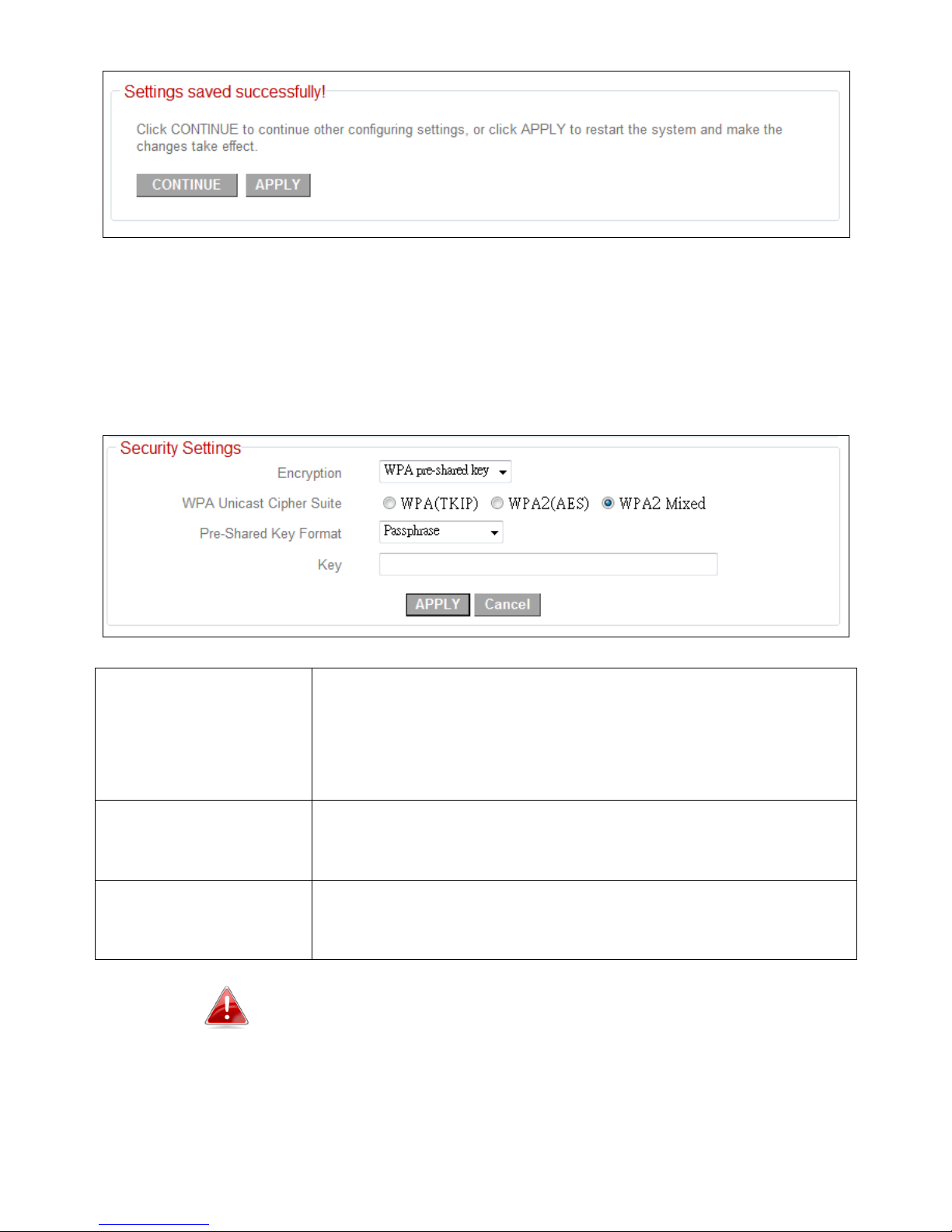
III-3-1-2. WPA Pre-shared Key
WPA pre-shared key is the recommended and most secure encryption type.
WPA Unicast Cipher
Suite
Select from WPA (TKIP), WPA2 (AES) or WPA2 Mixed.
AES is safer than TKIP, but not supported by all wireless
clients. WPA2(AES) or WPA2 is recommended if
supported by your wireless client. Mixed is
recommended if your client does not support AES.
Pre-shared Key
Format
Select the pre-shared key format from “Passphrase” (8
to 63 alphanumerical characters) or “Hex (64 characters
0 to 9 and a to f.)
Pre-shared Key
Please enter the key according to the key format you
selected above. For security reasons, it’s best to use a
complex, hard-to-guess key.
TKIP supports a maximum data rate of 54Mbps.
Click “APPLY” to save the changes. The following message will appear:
Page 30
30
Click “CONTINUE” to save the changes and continue configuring other settings,
or click “APPLY” to restart the system and make the changes take effect.
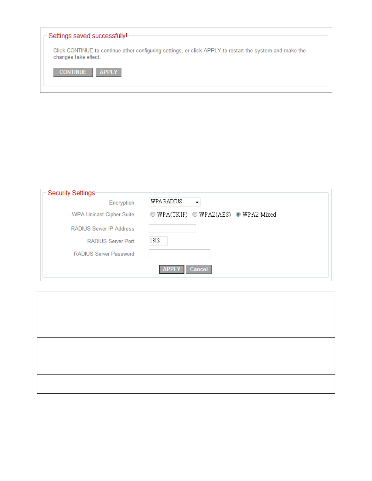
III-3-1-3. WPA Radius
WPA RADIUS is a combination of WPA encryption and RADIUS user
authentication. If you have a RADIUS authentication server, you can
authenticate the identity of every wireless client against a user database.
WPA Unicast Cipher
Suite
Select from WPA (TKIP), WPA2 (AES) or WPA2 Mixed.
AES is safer than TKIP, but not supported by all wireless
clients. WPA2(AES) or WPA2 is recommended if
supported by your wireless client. Mixed is
recommended if your client does not support AES.
RADIUS Server IP
address
Enter the IP address of the RADIUS authentication
server here.
RADIUS Server Port
Enter the port number of the RADIUS authentication
server here. Default value is 1812.
RADIUS Server
Password
Enter the password of the RADIUS authentication
server here.
Click “APPLY” to save the changes. The following message will appear:
Page 31

31
Click “CONTINUE” to save the changes and continue configuring other settings,
or click “APPLY” to restart the system and make the changes take effect.
Page 32

32
III-4. WPS Setting
WPS (Wi-Fi Protected Setup) is a simple way to
establish connections between WPS compatible
devices. WPS devices feature a WPS function which
can be activated by pushing a WPS button on the
device or from within the device’s
firmware/configuration interface. When WPS is
activated in the correct manner and at the correct
time for two compatible devices, they will
automatically connect.
By default, the WPS Settings page displays settings for
WPS between your extender and a wireless client. For
WPS Setup between your extender and router/access point, please refer back
to (II-3. WPS Setup).
The wireless extender supports two types of WPS for wireless clients: PBC
(Push Button Configuration) and PIN code. For PBC you can activate WPS on
the wireless extender by clicking the “Start PBC” button on the screen.
Page 33

33
Click the “Start PBC” button to activate WPS – do not push the
WPS/Reset button on the extender.
PIN code setup varies slightly in that it requires you to manually enter a PIN
code into each device via the WPS Settings before activating WPS.
WPS Status
Displays “Configured” or “unConfigured” depending
on whether WPS Settings for the extender have been
configured or not, either manually or using the WPS
button.
Device PIN Code
This is the WPS PIN code of the wireless extender for
use with other WPS-enabled wireless devices.
SSID
Displays the current SSID (the name used to identify
the wireless extender).
Authentication Mode
Displays the current wireless security/encryption type.
Passphrase Key
Shows the WPA passphrase here, though all characters
will be replaced by asterisks for security reasons. If
encryption is not set on the access point, this field will
be blank.
Config Mode
The configuration mode of the extender’s WPS setting
is displayed here. “Registrar” means the device acts as
an access point for a wireless client to connect to and
the wireless client(s) will follow the extender’s
wireless settings. “Enrollee” means the device acts a
wireless client and will follow the settings of the
wireless router/access point.
Configure via Push
Button
Click “Start PBC” to activate WPS on the extender.
Input Client PIN Code
Input the wireless client’s PIN code here and click
“Start PIN” to activate PIN code WPS. Refer to your
wireless client’s documentation if you are unsure of its
PIN code.
The WPS LED ( ) will flash slowly to indicate WPS is active. WPS will remain
active for two minutes. Within two minutes, activate WPS on your client
device (refer to client device’s user manual for guidance on how to do so) in
order to establish a connection. The WPS LED ( ) will display ON to indicate a
successful connection, and will remain ON for 5 minutes (see I-3. LED Status).
Page 34

34
III-5. Wireless Advanced
In “Advanced Setting” you can configure the advanced
features of the wireless extender. Please do not modify
these settings unless you know what effect the
changes will have on your access point; advanced
settings are for experienced users only.
Changing these settings can adversely affect the performance
of your wireless extender.
Page 35

35
Fragment Threshold
Set the fragment threshold of the wireless radio. The
default value is “2346”.
RTS Threshold
Set the RTS threshold of the wireless radio. The default
value is “2347”.
Beacon Interval
Set the beacon interval of the wireless radio. The
default value is “100”.
DTIM Period
Set the DTIM period of wireless radio. The default value
is “3”.
Data Rate
Set the wireless data transfer rate. The default value is
“Auto”.
N Data Rate
Set the data rate of 802.11n. The default value is
“Auto”.
Channel Width
Select wireless channel width.
Preamble Type
Set the wireless radio preamble type.
Broadcast ESSID
Set if the access point will broadcast its own ESSID. To
hide the ESSID of your extender select “Disable” - only
users who know the ESSID of your access point will be
able to connect.
WMM
WMM (Wi-Fi Multimedia) technology can improve the
performance of certain network applications, such as
audio/video streaming, network telephony (VoIP), and
others. When WMM is enabled, the extender will
prioritize different kinds of data and give higher priority
to applications which require instant responses. This
improves the performance of such network
applications.
CTS Protect
Enabling this setting will reduce the chance of radio
signal collisions between 802.11b and 802.11g wireless
access points. It’s recommended to set this option to
“Auto”.
TX Power
Set the power output of the wireless radio. Setting a
lower power output, provided it is still sufficient for
your range requirements, can potentially improve
security since malicious/unknown users in distant areas
will not be able to access your signal.
Click “APPLY” to save the changes. The following message will appear:
Page 36

36
Click “CONTINUE” to save the changes and continue configuring other settings,
or click “APPLY” to restart the system and make the changes take effect.
III-5-1. MAC Filtering
The MAC filtering feature allows you to define a list of
wireless devices permitted to connect to this access
point, identified by their unique MAC address. When a
device which is not listed as a permitted MAC address
attempts to connect to the extender, it will be denied.
Check the box “Enable Wireless Access Control” box to
enables MAC address filtering.
Page 37

37
Select SSID
Select which SSID to configure.
MAC Address Filtering Table:
Select
Check this box to select MAC address(es).
Delete Selected
Click this button to delete selected MAC address(es).
Delete All
Delete all MAC addresses in the table.
Reset
Uncheck all selected MAC address entries.
Enable Wireless
Access Control
Check this box to enable MAC address filtering.
MAC address
Enter a MAC address permitted to connect to the
extender. Only enter characters 0 to 9 or a to f.
Comment
Enter an optional comment associated with the
specified MAC address for reference/identification,
consisting of up to 16 alphanumerical characters.
Add
Add the MAC address entry to the list.
Clear
Remove all characters in the “MAC address” and
“Comments” fields.
Click “APPLY” to save the changes. The following message will appear:
Page 38

38
Click “CONTINUE” to save the changes and continue configuring other settings,
or click “APPLY” to restart the system and make the changes take effect.
III-6. System Utility
In “System Utility” you can configure the extender’s
administrative password and manage the extender’s IP
and DHCP settings.
You can change the password used to login to the browser-based configuration
interface here. It is advised to do so for security purposes.
Page 39

39
Current Password
Enter your current password. The default password is
1234.
New Password
Enter your desired new password here. You can use any
combination of letters, numbers and symbols up to 20
characters.
Re-Enter Password
Confirm your new password.
You can modify the IP address of the extender, enabling it to become a part of
your local area network. To do so, input the IP address, subnet mask and
gateway address into the corresponding fields.
IP Address
Specify an IP address here. This IP address will be
assigned to your extender, and will replace the default
IP address 192.168.10.1.
Subnet Mask
Input the subnet mask of the new IP address.
Gateway Address
Input the network’s gateway IP address.
DHCP Server
Select “Enabled” if you wish to use the DHCP function
of the extender, as detailed below.
Please write down and remember the new IP address you
assigned to the wireless extender. If you forget this IP address
Page 40

40
you may not be able to connect to the browser-based
configuration interface in the future.
For static IP users, the wireless extender needs to have an IP
address in the same subnet as your network, in order that you
can access the browser based configuration interface.
For example, if your static IP is 192.168.9.2 then you need to
assign the wireless extender an IP address in the range
192.168.9.x where x = 3–254. Each network device has a
unique IP address.
To ensure that you assign a correct IP address to the wireless
extender, you can also check the IP address of your router.
Please refer to V-1-4. How to Find your Router’s IP Address.
Your ISP can also provide you with such information as IP
address, subnet mask and gateway address.
If you are unable to connect to the browser based
configuration interface using http://edimax.setup, it is
possible that you assigned an incorrect IP address to the
extender. In this case you can reset the wireless extender back
to its default IP address. See II-4. Resetting The Wireless
Extender.
The extender can be configured to act as a DHCP server for your network. By
default DHCP is disabled. Enable DHCP by selecting “Enable” in the field
“DHCP Server”.
Default Gateway
Specify the IP address of the default gateway of your
network here.
Domain Name
Server IP
Input the IP address of the domain name server (DNS).
Start IP
Input the start address of the IP range.
End IP
Input the end address of the IP range.
Domain Name
Input the domain name for your network (optional).
Lease Time
Choose a lease time (the duration that every computer
can keep a specific IP address) of every IP address
assigned by the extender.
Click “APPLY” to save the changes. The following message will appear:
Page 41

41
Click “CONTINUE” to save the changes and continue configuring other settings,
or click “APPLY” to restart the system and make the changes take effect.
III-6-1. Time Setting
You can configure the time settings of your wireless
extender here. The date and time of the device can be
configured manually or can be synchronized with a
time server.
Page 42

42
Time Zone
Select the time zone of your country/ region. If your
country/region is not listed, please select another
country/region whose time zone is the same as yours.
Time Server Address
The extender supports NTP (Network Time Protocol)
for automatic time and date setup. Input the host
name or IP address of the IP server manually.
Daylight Savings
If your country/region uses daylight saving time, please
check the “Enable Function” box and select the start
and end date.
Click “APPLY” to save the changes. The following message will appear:
Click “CONTINUE” to save the changes and continue configuring other settings,
or click “APPLY” to restart the system and make the changes take effect.
III-6-2. Scheduling Setting
The wireless extender includes a scheduling function,
where power saving functions and an automatic
reboot can be automated for specific times. By default,
scheduling setting is disabled. Please select “Enable” if
you wish to continue.
Page 43

43
Click “Add” to open a new window and create a new scheduled event.
Ensure that you have correctly configured the time settings of
your wireless extender before enabling the scheduling
function.
Page 44

44
Service
Select the type of event to be scheduled. “Wireless off”
will switch off wireless and “Auto reboot” will restart
the device.
Schedule Description
Assign the event an optional name or description for
reference.
Start Time
Specify a start time (hh.mm) for the event on one or
more specified days.
End Time
Specify an end time (hh.mm) for the event, for a
specific day or to recur every day.
Select
Check the box to select and confirm your event.
Click “Save” to save your scheduled event and then click “OK”.
The scheduled event should now be listed. Up to 10 events can be scheduled.
Edit
Select the type of event to be scheduled. “Wireless off”
will switch off wireless and “Auto reboot” will restart
the device.
Delete
Assign the event an optional name or description for
reference.
Click “APPLY” to save the changes. The following message will appear:
Page 45

45
Click “CONTINUE” to save the changes and continue configuring other settings,
or click “APPLY” to restart the system and make the changes take effect.
II-7. Configuration Tool
On the configuration tool page you can backup the
extender’s current settings, restore the settings to a
previously saved version or reset the extender back to
it’s original, factory default state.
Restoring settings to the factory default will restore all
settings, configurations and passwords back to the factory
default.
Page 46

46
You can also reset the device to factory defaults by pressing
and holding the Reset/WPS button for at least 10 seconds.
See II-3. Resetting The Wireless Extender.
Backup Settings
Click “Save” to save the current settings of the extender
as a config.bin file to your specified location.
Restore Settings
Click the browse button to locate a previously saved
config.bin file and then click “Upload” to upload the file
and replace your current settings.
Restore to Factory
Defaults
Click “Reset” to restore settings to the factory default.
A pop-up window will appear and ask you to confirm,
please click “Ok” and the extender will restart. A status
bar will indicate the progress of the restart.
Page 47

47
III-7-1. Diagnosis
Using the diagnosis tool, you can ping a specific IP
address and automatically reboot the device if there is
no response.
Watchdog and
reboot device
Select “Enable” or “Disable” for the automatic reboot
function.
Ping address
Specify the IP address to ping.
Time interval
Specify the frequency of the ping as a time interval, in
minutes. Enter a value from 1-60.
Page 48

48
III-7-2. Firmware Upgrade
The wireless extender’s firmware upgrade feature
allows you to upgrade the system firmware to a more
recent version. You can download the latest firmware
from the Edimax website.
Do not switch off or disconnect the access
point during a firmware upgrade, as this could
damage the device.
It is recommended that you use a wired
Ethernet connection to upload the firmware
file.
Browse
Click “Browse” to open a window and locate the
firmware file.
CANCEL
Click “CANCEL” to cancel and clear the selected file
from the “Browse” box.
APPLY
Click “APPLY” to upgrade to the selected firmware file.
A pop up window will ask you to confirm, and inform
you that the device may not respond for up to a minute
after the upgrade. Please click “OK”. A status bar will
show the progress of the upgrade.
Page 49

49
III-7-3. Reboot
If the wireless extender malfunctions or is not
responding, then it is recommended that you reset the
device. This feature is useful if the location of the
access point is not convenient to physically use the
hardware reset button.
A system reboot will restart the device without
affecting existing settings.
If the wireless extender is still not responding
after a reset, then switch off the device by
disconnecting the power supply and wait for
10 seconds before reconnecting the power.
APPLY
Click “APPLY” to reboot the system. You will be asked to confirm,
and informed that the reboot may take a while. A status bar will
indicate the progress..
Page 50

50
IV. POWERLINE UTILITY SOFTWARE
The included CD-ROM contains Powerline utility software, which enables you
to manage and configure your Powerline network in more detail. The utility
enables you to manage all connected Powerline adapters.
IV-1. Installation
Before installating the utility software, please uninstall any
existing Powerline utility software you may already have.
To install the utility software, insert the CD into your CD-ROM drive and the
setup wizard should begin automatically. If not, please manually locate and
open the “AutoRun.exe” file in the CD.
IV-1.1 Win 8
Step 1 Before installing the utility software, make sure that no other
powerline utility is installed on your computer. If any other utility
software is installed, uninstall it and reboot the computer.
Step 2 Insert the CD into your CD-ROM drive. When the following EZmax
Wizard appears, select your model.
Page 51

51
Step 3 Then click “Setup Utility”.
Page 52

52
Step 4 Click right button on WinPCap4.1.2 then click “Properties”.
Step 5 Click Compatibility tab and check “Run this program in compatibility
mode for:", then select Windows 7, then click “Apply”.
Page 53

53
Step 6 Then click “WinPcap_4_1_2”. The wizard will guide you through the
setup process.
Page 54

54
Step 7 When the following WinPcap Compatibility Assistant appears, select
Run the program without getting help.
Page 55

55
Step 8 After the installation is complete, click “Finish”.
Page 56

56
Step 9 Click the “Edimax PowerLine Utility”, the “PLC 500Mbps Utility”
appears, click “Next” to continue.
Page 57

57
Step 10 Select where you want to install the utility software, and then click
“Next”.
Step 11 After the installation is complete, click “Close”.
Page 58

58
Step 12 An icon will appear on your desktop. Click the icon to open the
utility software.
Note: You can manage all the connected powerline adapters with the
utility software. However, installing the utility software is
optional.
Page 59

59
IV-1.2 Win XP/Vista / 7
Step 1 Before installing the utility software, make sure that no other
powerline utility is installed on your computer. If any other utility
software is installed, uninstall it and reboot the computer.
Step 2 Insert the CD into your CD-ROM drive. When the following EZmax
Wizard appears, select your model.
Step 3 Then click “Setup Utility”.
Page 60

60
Step 4 If you have not installed WinPcap version 4.1.2 (or higher) on your
computer before. The wizard will guide you through the setup process.
Page 61

61
Page 62

62
Step 5 When the “Edimax PowerLine Utility” setup wizard appears, click
“Next” to continue.
Step 6 In the “License Agreement” screen, please select “I Agree” and then
click “Next” to continue.
Page 63

63
Step 7 Select where you want to install the utility software, and then click
“Next”.
Step 8 If you confirm to install the utility, click “Next”.
Page 64

64
Step 9 After the installation is complete, click “Close”.
Step 10 An icon will appear on your desktop. Click the icon to open the
utility software.
Note: You can manage all the connected powerline adapters with the
utility software. However, installing the utility software is
optional.
Page 65

65
IV-2. Using the Utility Software
IV-2-1. Main Tab
The “Main” tab provides a list of powerline adapters connected to the
network. The upper panel displays local powerline adapters. The lower panel
displays remote powerline adapters in the network.
Set Name
Select a device and click “Set Name” to rename the
device.
Enter Password
By default, this column is blank. Select a device and click
“Enter Password” to set up a password for the device.
Scan
Click “Scan” and the utility software will perform an
immediate scan of other remote powerline adapters. By
default, the utility automatically scans every few seconds.
Page 66

66
IV-2-2. Diagnostics Tab
The “Diagnostics” tab displays the system information and history of all
remote devices.
The upper panel displays technical data concerning the software and
hardware on the host computer and the lower panel displays the history of all
remote devices.
Page 67

67
IV-2-3. About Tab
The “About” tab contains some basic information about the software. You
can also enable or disable the autoscan function under “Preferences”.
Page 68

68
V. APPENDIX
V-1. Configuring your IP address
Before you use the wireless extender, please make sure your computer is set
to use a dynamic IP address. This means your computer can obtain an IP
address automatically from a DHCP server. This is a simple procedure, which is
explained step by step in V-1-1. How to configure your computer to use a
dynamic IP address.
Static IP users, please make a note of your static IP before you
change it or switch to a dynamic IP address.
Unfortunately, not all networks support DHCP capability. In this case, you need
to use a static IP address for the wireless extender and your PC or Macintosh.
The wireless extender uses the default IP address 192.168.10.1, which may
not be in the same IP address subnet of your network; meaning you are
unable to access the browser based configuration interface. So, you need to
modify the IP address of your PC or Macintosh to 192.168.10.x (x = 2 – 254) in
order to access the browser-based configuration interface.
The procedure for doing so varies across different operating systems; please
follow the guide appropriate for your operating system in IV-1-2. How to
modify the IP address of your PC or Macintosh.
Note: For guidance on how to assign a new IP address to
the wireless extender, so that it is within the same IP
address subnet of your network, please refer to III-6.
System Utility. In cases where you need to modify the IP
of your PC or Macintosh in order to access the browser
based configuration interface, if the default IP of the
wireless extender remains unchanged, you may need to
repeat this process and modify the IP of your PC or
Macintosh every time you wish to configure the wireless
extender.
V-1-1. How to Configure Your Computer to Use a Dynamic IP Address
Please follow the instructions appropriate for your operating system.
Page 69

69
V-1-1-1. Windows XP
1. Click the “Start” button (it should be located in the lower-left corner of your
computer), then click “Control Panel”. Double-click the “Network and
Internet Connections” icon, click “Network Connections”, and then
double-click “Local Area Connection”. The “Local Area Connection Status”
window will then appear, click “Properties”.
2. Select “Obtain an IP address automatically” and “Obtain DNS server
address automatically”, then click “OK”.
Page 70

70
V-1-1-2. Windows Vista
1. Click the “Start” button (it should be located in the lower-left corner of your
computer), then click “Control Panel”. Click “View Network Status and
Tasks”, then click “Manage Network Connections”. Right-click “Local Area
Network”, then select “Properties”. The “Local Area Connection Properties”
window will then appear, select “Internet Protocol Version 4 (TCP / IPv4)”,
and then click “Properties”.
Page 71

71
2. Select “Obtain an IP address automatically” and “Obtain DNS server
address automatically”, then click “OK”.
Page 72

72
V-1-1-3. Windows 7
1. Click the “Start” button (it should be located in the lower-left corner of your
computer), then click “Control Panel”.
2. Under “Network and Internet” click “View network status and tasks”.
3. Click “Local Area Connection”.
Page 73

73
4. Click “Properties”.
5. Select “Internet Protocol Version 4 (TCP/IPv6) and then click “Properties”.
Page 74

74
3. Select “Obtain an IP address automatically” and “Obtain DNS server
address automatically”, then click “OK”.
IV-1-1-4. Windows 8
1. From the Windows 8 Start screen, you need to switch to desktop mode.
Move your curser to the bottom left of the screen and click.
Page 75

75
2. In desktop mode, click the File Explorer icon in the bottom left of the
screen, as shown below.
3. Right click “Network” and then select “Properties”.
Page 76

76
4. In the window that opens, select “Change adapter settings” from the left
side.
5. Choose your connection and right click, then select “Properties”.
Page 77

77
6. Select “Internet Protocol Version 4 (TCP/IPv6) and then click “Properties”.
4. Select “Obtain an IP address automatically” and “Obtain DNS server
address automatically”, then click “OK”.
Page 78

78
V-1-1-5. Mac OS
Note: Please ensure that your wireless extender is
switched on and connected to your Macintosh via
Ethernet cable before you begin.
1. Have your Macintosh computer operate as usual, and click on “System
Preferences”.
2. In System Preferences, click on “Network”.
Page 79

79
3. Here you will see all of your network connections. Network Preferences will
now display an Ethernet adapter, as shown below. The status of “Ethernet”
should be “Connected”.
4. Click on “Ethernet” in the left panel and then click the drop down arrow for
the menu labeled “Configure IPv4” in the right panel. From the drop down
menu, select “Using DHCP” and then click “Apply”.
Page 80

80
V-1-2. How to Modify the IP Address of Your PC or Macintosh
Please follow the instructions appropriate for your operating system. In the
following examples we use the IP address 192.168.10.20 though you can use
any IP address in the range 192.168.9.x (x = 3 – 254) in order to access the
browser based configuration interface.
Note: Please make a note of your static IP before you
change it. This is for your convenience if you wish to
modify the IP address of the wireless extender in
future. To modify the IP address of the wireless
extender, please refer to III-6. System Utility.
V-1-2-1. Windows XP
1. Click the “Start” button (it should be located in the lower-left corner of your
computer), then click “Control Panel”. Double-click the “Network and
Internet Connections” icon, click “Network Connections”, and then
double-click “Local Area Connection”. The “Local Area Connection Status”
window will then appear, click “Properties”.
2. Select “Use the following IP address”, then input the following values:
Page 81

81
Note: Your existing static IP address will be displayed
in the “IP address” field before you replace it. Please
make a note of this IP address, subnet mask, default
gateway and DNS server addresses.
IP address: 192.168.10.20
Subnet Mask: 255.255.255.0
Click ‘OK’ when finished.
V-1-2-2. Windows Vista
1. Click the “Start” button (it should be located in the lower-left corner of your
computer), then click “Control Panel”. Click “View Network Status and
Tasks”, then click “Manage Network Connections”. Right-click “Local Area
Network”, then select “Properties”. The “Local Area Connection Properties”
window will then appear, select “Internet Protocol Version 4 (TCP / IPv4)”,
and then click “Properties”.
2. Select “Use the following IP address”, then input the following values:
Page 82

82
Note: Your existing static IP address will be displayed
in the “IP address” field before you replace it. Please
make a note of this IP address, subnet mask, default
gateway and DNS server addresses.
IP address: 192.168.10.20
Subnet Mask: 255.255.255.0
Click ‘OK’ when finished.
V-1-2-3. Windows 7
1. Click the “Start” button (it should be located in the lower-left corner of your
computer), then click “Control Panel”.
2. Under “Network and Internet” click “View network status and tasks”.
Page 83

83
3. Click “Local Area Connection”.
4. Click “Properties”.
Page 84

84
5. Select “Internet Protocol Version 4 (TCP/IPv6) and then click “Properties”.
6. Select “Use the following IP address”, then input the following values:
Note: Your existing static IP address will be displayed
in the “IP address” field before you replace it. Please
make a note of this IP address, subnet mask, default
gateway and DNS server addresses.
IP address: 192.168.10.20
Subnet Mask: 255.255.255.0
Click ‘OK’ when finished.
V-1-2-4. Windows 8
1. From the Windows 8 Start screen, you need to switch to desktop mode.
Move your curser to the bottom left of the screen and click.
Page 85

85
2. In desktop mode, click the File Explorer icon in the bottom left of the
screen, as shown below.
3. Right click “Network” and then select “Properties”.
Page 86

86
4. In the window that opens, select “Change adapter settings” from the left
side.
5. Choose your connection and right click, then select “Properties”.
Page 87

87
6. Select “Internet Protocol Version 4 (TCP/IPv4) and then click “Properties”.
7. Select “Use the following IP address”, then input the following values:
Page 88

88
Note: Your existing static IP address will be displayed
in the “IP address” field before you replace it. Please
make a note of this IP address, subnet mask, default
gateway and DNS server addresses.
IP address: 192.168.10.20
Subnet Mask: 255.255.255.0
Click ‘OK’ when finished.
V-1-2-5. Mac OS
Note: Please ensure that your wireless extender is
switched on and connected to your Macintosh via
Ethernet cable before you begin.
1. Have your Macintosh computer operate as usual, and click on “System
Preferences”
2. In System Preferences, click on “Network”.
3. Here you will see all of your network connections. Network Preferences will
now display an Ethernet adapter, as shown below. The status of “Ethernet”
should be “Connected”.
Page 89

89
4. Click on “Ethernet” in the left panel and then click the drop down arrow for
the menu labeled “Configure IPv4” in the right panel. From the drop down
menu, select “Manually”.
5. In the panel on the right side, enter IP address 192.168.10.20 and subnet
mask 255.255.255.0. Click on “Apply”.
Page 90

90
Note: Your existing static IP address will be displayed
in the “IP address” field before you replace it. Please
make a note of this IP address, subnet mask, router IP
and DNS server address.
6. In the left sidebar, “Ethernet” should now display “Connected” as shown
below. In the right panel, you should see the IP address 192.168.10.20 and
subnet mask 255.255.255.0.
V-1-3. How to Find Your Network Security Key
To find your network security key, please follow the instructions appropriate
for your operating system.
Note: If you are using Windows XP or earlier, please
contact your ISP or router manufacturer to find your
network security key.
V-1-3-1. Windows 7 & Windows Vista
1. Open “Control Panel” and click on “Network and Internet” in the top menu.
2. Click on “View network status and tasks” which is under the heading
“Network and Sharing Center”.
Page 91

91
3. Click on “Manage wireless networks” in the left menu.
4. You should see the profile of your Wi-Fi network in the list. Right click on
your Wi-Fi network and then click on “Properties”.
5. Click on the “Security” tab, and then check the box labeled “Show
characters”. This will show your network security key. Click the “Cancel”
button to close the window.
Page 92

92
V-1-3-2. Windows 8
8. From the Windows 8 Start screen, you need to switch to desktop mode.
Move your curser to the bottom left of the screen and click.
9. In desktop mode, click the network icon in the bottom right corner.
Page 93

93
10. Select your Wi-Fi connection from the list and right click. Select “View
connection properties”.
11. In the window that opens, click the “Security” tab and check the box
labeled “Show characters”. Your network security key will be displayed in
the field “Network security key”.
Page 94

94
Page 95

95
V-1-3-3. Mac
1. Open a new Finder window, and select “Applications” from the menu on
the left side. Open the folder labeled “Utilities” and then open the
application “Keychain Access”.
2. Select “Passwords” from the sub-menu labeled “Category” on the left side,
as shown below. Then search the list in the main panel for the SSID of your
network. In this example, the SSID is “EdimaxWireless” – though your SSID
will be unique to your network.
Page 96

96
3. Double click the SSID of your network and you will see the following
window.
4. Check the box labeled “Show password” and you will be asked to enter your
administrative password, which you use to log into your Mac. Enter your
password and click “Allow”.
Page 97

97
Your network security password will now be displayed in the field next to
the box labeled “Show password”. In the example below, the network
security password is “edimax1234”. Please make a note of your network
security password.
Page 98

98
V-1-4. How to Find Your Router’s IP Address
To find your router’s IP address, please follow the instructions appropriate for
your operating system.
V-1-4-1. Windows XP, Vista & 7
1. Go to “Start”, select “Run” and type “cmd”, then press Enter or click “OK”.
2. A new window will open, type “ipconfig” and press Enter.
Page 99

99
3. Your router’s IP address will be displayed next to “Default Gateway”.
V-1-4-2. Windows 8
1. From the Windows 8 Start screen, move your curser to the top right corner
of the screen to display the Charms bar.
Page 100

100
12. Click “Search” and enter “cmd” into the search bar. Click the “Command
Prompt” app which be displayed on the left side.
13. A new window will open, type “ipconfig” and press Enter.
 Loading...