

Page 1
ES-1008P V2 /GS-1008P V2
Quick Installation Guide
02-2017 v1.0
Page 2
Model No.
QIG
Power Cord
PoE+ Switch
Rack-Mount Kit
ES-1008P V2: 8-Port Fast Ethernet PoE+ Switch
GS-1008P V2: 8-Port Gigabit PoE+ Switch
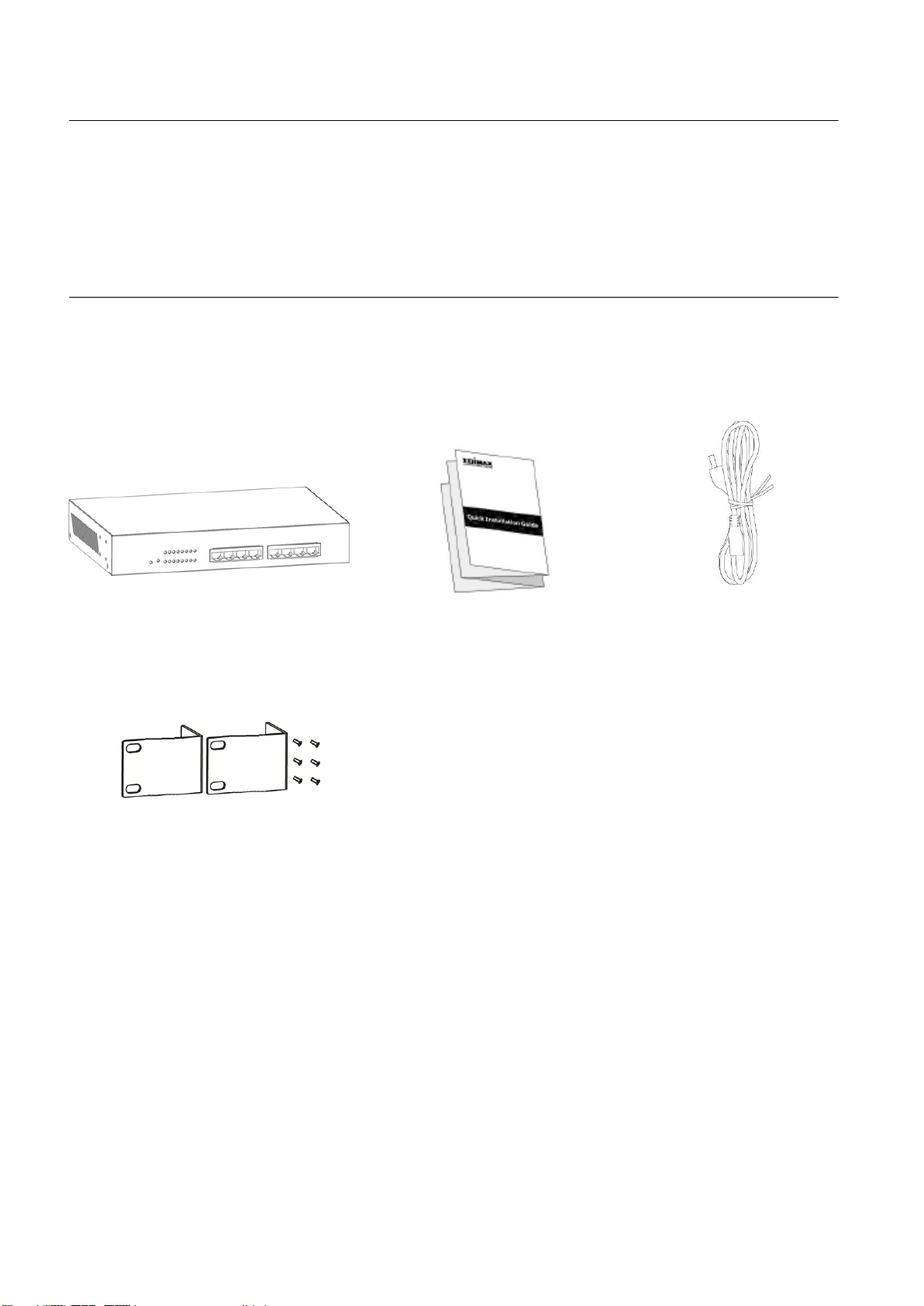
Package Contents
Before you start using this product, please check if there is anything missing in
the package, and contact your dealer to claim the missing item(s):
Page 3
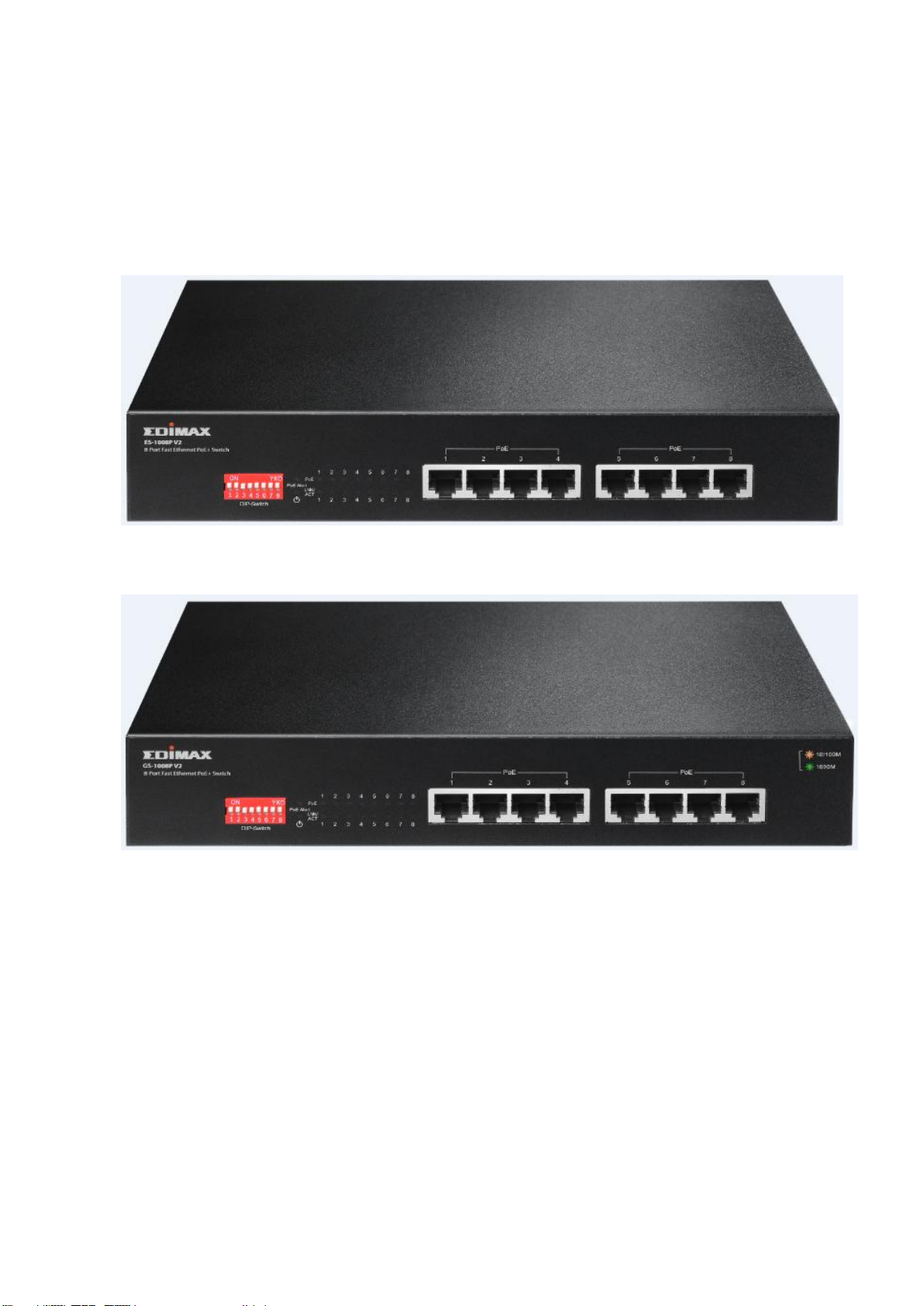
I-2. Hardware Overview
Front Panel:
Please refer to the following description for the front panel:
ES-1008P V2
GS-1008P V2
Page 4
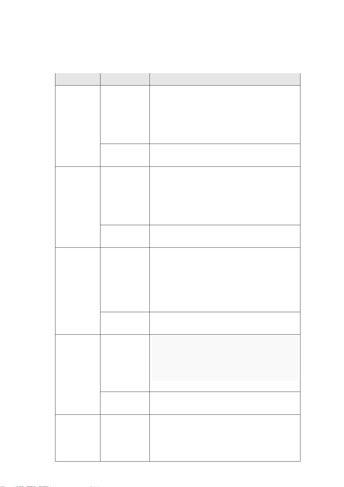
DIP Switch Definition:
DIP Switch
Status
Description
1
(Extend)
On
This mode makes the PoE Port 1~2
operate at auto-negotiation 10Mbps
speed duplex mode only, but the
delivery distance of PoE power and
network data can reach 200m.
Off
(default)
This mode makes the PoE Port 1~2
operate as a genral switch.
2
(Extend)
On
This mode makes the PoE Port 3~4
operate at auto-negotiation 10Mbps
speed duplex mode only, but the
delivery distance of PoE power and
network data can reach 200m.
Off
(default)
This mode makes the PoE Port 3~4
operate as a genral switch.
3
(VLAN)
On
This mode makes the PoE+ switch
operate as a VLAN isolation switch
and port 1 to port 4 will isolate
respectively., port 1 to port 4 can only
communicate with port 5 (uplink
port).
Off
(default)
This mode makes the PoE+ switch
operate as a genral switch.
4
(QoS)
On
This mode makes the PoE+ switch
operate as a QOS switch, it follows the
802.1p QoS, video and voice with high
priority.
Off
This mode makes the PoE+ switch
operate as a genral switch.
5
(Extend)
On
This mode makes the PoE Port 5
operate at auto-negotiation 10Mbps
speed duplex mode only, but the
delivery distance of PoE power and
The front pnael of PoE+ switch provies four pins DIP Switch. The detailed
descriptions are shown nin the following table.
Page 5

network data can reach 200m.
Off
(default)
This mode makes the PoE Port 5
operate as a genral switch.
6
(Extend)
On
This mode makes the PoE Port 6
operate at auto-negotiation 10Mbps
speed duplex mode only, but the
delivery distance of PoE power and
network data can reach 200m.
Off
(default)
This mode makes the PoE Port 6
operate as a genral switch.
7
(Extend)
On
This mode makes the PoE Port 7
operate at auto-negotiation 10Mbps
speed duplex mode only, but the
delivery distance of PoE power and
network data can reach 200m.
Off
This mode makes the PoE Port 7
operate as a genral switch.
8
(VLAN)
On
This mode makes the PoE+ switch
operate as a VLAN isolation switch
and port 5 to port 7 will isolate
respectively., port 5 to port 7 can
only communicate with port 1,2,3,4
& 8 uplink port.
Off
This mode makes the PoE+ switch
operate as a genral switch.
Please note, after truning ON the DIP switch you will have to Reboot the
switch.
After installing the switch, you can check its status from the LED inducators
on the front panel shown below.
Page 6

LED
Color
LED Status
Description
Power
Green
On
Switch is on.
Off
Switch is off.
LNK/ACT
Green
On
Connected to 10/100M network.
(Supports ES-1008P V2 only)
Connected to 10/100/1000M
network. (Supports GS-1008P V2 only)
Flashing
Transferring/receiving data.
Off
No device is connected.
PoE
Green
On
Feeding power to PoE devices.
Off
PoE function is not active.
PoE Alert
Red
On
Total PoE power consumed is
exceeding PoE budget.
Off
Total PoE power is within PoE budget.
LED Definitions:
Back Panel:
Operating Environment
This switch must be installed and operated within the limits of the specified
operating temperature 0 - 40°C (32 - 104°F) and humidity (10 - 90%
non-condensing).
- Do not place objects on top of the unit.
Page 7

- Do not obstruct any vents at the sides of the unit.
- Do not position the unit close to any heating source such as a heater, radiator
or in direct exposure to sun.
- Take care to ensure the unit does not come into contact with water. Consider
using a dehumidifier to reduce humidity and prevent moisture entering the
unit.
Connecting to Network Devices
The RJ-45 ports on the switch support Auto-MDI/MDI-X which allows either
straight-through or cross-over type cables to connect this switch to a workstation
or switch.
Connect one end of the network cable to the RJ-45 port on the side panel, and
connect the other end of the network cable to the RJ-45 port on the network
device. Follow the same procedure to connect all RJ-45 ports of the switch.
The UTP network cables must comply with EIA/TIA 568 specifications and
Category 5 standard for data transmission. The maximum length for a UTP cable
segment between the switch and connected devices is 100 meters (300ft).
Once the network cable is connected to both ends and the attached network
device is powered on, the green LNK/ACT LED should be lit.
Connecting The Power
Connect the power adapter to the power connector of the unit; the green power
LED on the front panel should be lit.
Page 8

Page 9

TROUBLESHOOTING
1. Power LED is not lit.
Check if the power cord is properly connected to the external power adapter and
the power source. Make sure the DC power jack is firmly plugged into the power
socket of the switch.
2. Link/Activity (LNK/ACT) LED is not lit when connected to devices.
- Ensure that the network device attached to the switch is switched on.
- Check the network cable; ensure it is properly connected to the switch and the
network device.
- Check the network cable; ensure the UTP cable complied with EIA/TIA 568 and
Category 5 specifications.
[!] Contact your dealer if problems persist.
Page 10

Federal Communication Commission Interference Statement
This equipment has been tested and found to comply with the limits for a Class B digital device, pursuant to Part 15 of
FCC Rules. These limits are designed to provide reasonable protection against harmful interference in a residential
installation. This equipment generates, uses, and can radiate radio frequency energy and, if not installed and used in
accordance with the instructions, may cause harmful interference to radio communications. However, there is no
guarantee that interference will not occur in a particular installation. If this equipment does cause harmful
interference to radio or television reception, which can be determined by turning the equipment off and on, the user
is encouraged to try to correct the interference by one or more of the following measures:
1. Reorient or relocate the receiving antenna.
2. Increase the separation between the equipment and receiver.
3. Connect the equipment into an outlet on a circuit different from that to which the receiver is connected.
4. Consult the dealer or an experienced radio technician for help.
FCC Caution
This device and its antenna must not be co-located or operating in conjunction with any other antenna or transmitter.
This device complies with Part 15 of the FCC Rules. Operation is subject to the following two conditions: (1) this device
may not cause harmful interference, and (2) this device must accept any interference received, including interference
that may cause undesired operation. Any changes or modifications not expressly approved by the party responsible
for compliance could void the authority to operate equipment.
Federal Communications Commission (FCC) Radiation Exposure Statement
This equipment complies with FCC radiation exposure set forth for an uncontrolled environment. In order to avoid the
possibility of exceeding the FCC radio frequency exposure limits, human proximity to the antenna shall not be less
than 2.5cm (1 inch) during normal operation.
Federal Communications Commission (FCC) RF Exposure Requirements
SAR compliance has been established in the laptop computer(s) configurations with PCMCIA slot on the side near the
center, as tested in the application for certification, and can be used in laptop computer(s) with substantially similar
physical dimensions, construction, and electrical and RF characteristics. Use in other devices such as PDAs or lap pads
is not authorized. This transmitter is restricted for use with the specific antenna tested in the application for
certification. The antenna(s) used for this transmitter must not be co-located or operating in conjunction with any
other antenna or transmitter.
R&TTE Compliance Statement
This equipment complies with all the requirements of DIRECTIVE 1999/5/EC OF THE EUROPEAN PARLIAMENT AND THE
COUNCIL of March 9, 1999 on radio equipment and telecommunication terminal equipment and the mutual
recognition of their conformity (R&TTE). The R&TTE Directive repeals and replaces in the directive 98/13/EEC
(Telecommunications Terminal Equipment and Satellite Earth Station Equipment) As of April 8, 2000.
Safety
This equipment is designed with the utmost care for the safety of those who install and use it. However, special
attention must be paid to the dangers of electric shock and static electricity when working with electrical equipment.
All guidelines of this and of the computer manufacture must therefore be allowed at all times to ensure the safe use of
the equipment.
EU Countries Intended for Use
The ETSI version of this device is intended for home and office use in Austria, Belgium, Bulgaria, Cyprus, Czech,
Denmark, Estonia, Finland, France, Germany, Greece, Hungary, Ireland, Italy, Latvia, Lithuania, Luxembourg, Malta,
Netherlands, Poland, Portugal, Romania, Slovakia, Slovenia, Spain, Sweden, Turkey, and United Kingdom. The ETSI
version of this device is also authorized for use in EFTA member states: Iceland, Liechtenstein, Norway, and
Switzerland.
EU Countries Not Intended for Use
None
Page 11

EU Declaration of Conformity
English: This equipment is in compliance with the essential requirements and other relevant provisions
of Directive 1995/5/EC, 2009/125/EC, 2006/95/EC, 2011/65/EC.
Français: Cet équipement est conforme aux exigences essentielles et autres dispositions de la directive
1995/5/CE, 2009/125/CE, 2006/95/CE, 2011/65/CE.
Čeština: Toto zařízení je v souladu se základními požadavky a ostatními příslušnými ustanoveními
směrnic 1995/5/ES, 2009/125/ES, 2006/95/ES, 2011/65/ES.
Polski: Urządzenie jest zgodne z ogólnymi wymaganiami oraz szczególnymi warunkami określonymi
Dyrektywą UE 1995/5/EC, 2009/125/EC, 2006/95/EC, 2011/65/EC..
Română: Acest echipament este în conformitate cu cerinţele esenţiale şi alte prevederi relevante ale
Directivei 1995/5/CE, 2009/125/CE, 2006/95/CE, 2011/65/CE.
Русский: Это оборудование соответствует основным требованиям и положениям Директивы
1995/5/EC, 2009/125/EC, 2006/95/EC, 2011/65/EC.
Magyar: Ez a berendezés megfelel az alapvető követelményeknek és más vonatkozó irányelveknek
(1995/5/EK, 2009/125/EK, 2006/95/EK, 2011/65/EK).
Türkçe: Bu cihaz 1995/5/EC, 2009/125/EC, 2006/95/EC, 2011/65/EC direktifleri zorunlu istekler ve diğer
hükümlerle ile uyumludur.
Українська: Обладнання відповідає вимогам і умовам директиви 1995/5/EC, 2009/125/EC, 2006/95/EC,
2011/65/EC.
Slovenčina: Toto zariadenie spĺňa základné požiadavky a ďalšie príslušné ustanovenia smerníc 1995/5/ES,
2009/125/ES, 2006/95/ES, 2011/65/ES.
Deutsch: Dieses Gerät erfüllt die Voraussetzungen gemäß den Richtlinien 1995/5/EC, 2009/125/EC,
2006/95/EC, 2011/65/EC.
Español: El presente equipo cumple los requisitos esenciales de la Directiva 1995/5/EC, 2009/125/EC,
2006/95/EC, 2011/65/EC.
Italiano: Questo apparecchio è conforme ai requisiti essenziali e alle altre disposizioni applicabili della
Direttiva 1995/5/CE, 2009/125/CE, 2006/95/CE, 2011/65/CE.
Nederlands: Dit apparaat voldoet aan de essentiële eisen en andere van toepassing zijnde bepalingen van
richtlijn 1995/5/EC, 2009/125/EC, 2006/95/EC, 2011/65/EC..
Português: Este equipamento cumpre os requesitos essênciais da Directiva 1995/5/EC, 2009/125/EC,
2006/95/EC, 2011/65/EC.
Norsk: Dette utstyret er i samsvar med de viktigste kravene og andre relevante regler i Direktiv
1995/5/EC, 2009/125/EC, 2006/95/EC, 2011/65/EC.
Svenska: Denna utrustning är i överensstämmelse med de väsentliga kraven och övriga relevanta
bestämmelser i direktiv 1995/5/EG, 2009/125/EG, 2006/95/EG, 2011/65/EG.
Dansk: Dette udstyr er i overensstemmelse med de væ sentligste krav og andre relevante forordninger i
direktiv 1995/5/EC, 2009/125/EC, 2006/95/EC, 2011/65/EC.
suomen kieli: Tämä laite täyttää direktiivien 1995/5/EY, 2009/125/EY, 2006/95/EY, 2011/65/EY oleelliset
vaatimukset ja muut asiaankuuluvat määräykset.
-----------------------------------------------------------------------------------------------------------------------
WEEE Directive & Product Disposal
At the end of its serviceable life, this product should not be treated as household or general waste. It should
be handed over to the applicable collection point for the recycling of electrical and electronic equipment, or
returned to the supplier for disposal.
Page 12

Declaration of Conformity
We, Edimax Technology Co., Ltd., declare under our sole responsibility, that the
equipment described below complies with the requirements of the European R&TTE
directives.
Equipment:
ES-1008P V2 8-Port Fast Ethernet PoE+ Switch
GS-1008P V2 8-Port Gigabit PoE+ Switch
Model No.:
ES-1008P V2 / GS-1008P V2
The following European standards for essential requirements have been followed:
Directives 2014/30/EC
EMC
:
EN55022:2010+AC:2011 Class A
EN55024:2010
EN61000-3-2:2014 Class A
EN61000-3-3:2013
Safety (LVD)
:
EN 60950-1:2006 + A11:2009 + A1:2010 +
A12:2011+A2:2013
IEC60950-1:2005(Second Edition)+Am
1:2009+Am2:2013
Edimax Technology Co., Ltd.
No. 3, Wu Chuan 3rd Road,
Wu-Ku Industrial Park,
New Taipei City, Taiwan
Date of Signature:
Feb., 2017
Signature:
Printed Name:
Albert Chang
Title:
Director
Edimax Technology Co., Ltd.
Page 13

Page 14

 Loading...