

Page 1

ES-3305P V2 / ES-3308P V2
Quick Installation Guide
09-2013 / v1.0
1
Page 2

COPYRIGHT
Copyright Edimax Technology Co., Ltd. all rights reserved. No part of this
publication may be reproduced, transmitted, transcribed, stored in a retrieval
system, or translated into any language or computer language, in any form or by
any means, electronic, mechanical, magnetic, optical, chemical, manual or
otherwise, without the prior written permission from Edimax Technology Co.,
Ltd.
Edimax Technology Co., Ltd. makes no representations or warranties, either
expressed or implied, with respect to the contents hereof and specifically
disclaims any warranties, merchantability, or fitness for any particular purpose.
Edimax Technology Co., Ltd. reserves the right to revise this publication and to
make changes from time to time in the contents hereof without the obligation to
notify any person of such revision or changes.
The product you have purchased and the setup screen may appear slightly
different from those shown in this QIG. The specification is subject to change
without notice. Please visit our web site www.edimax.com for the update. All
brand and product names mentioned in this manual are trademarks and/or
registered trademarks of their respective holders.
Edimax Technology Co., Ltd.
Add: No. 3, Wu‐Chuan 3rd Rd., Wu‐Ku Industrial Park, New Taipei City, Taiwan
Tel: +886‐2‐77396888
Email: sales@edimax.com.tw
2
Page 3
PRODUCT INTRODUCTION
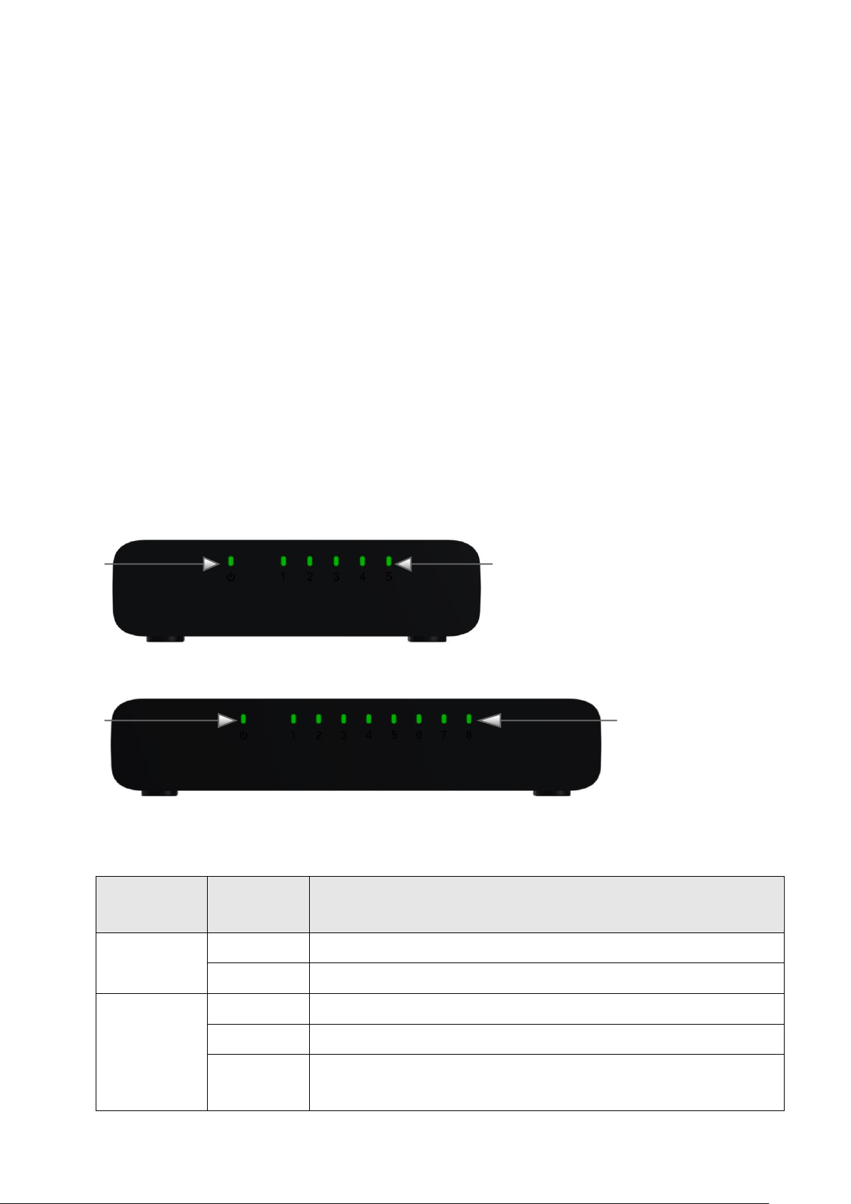
LED Name
Light
Status
Description
PWR
On
Switch is on
Off
Switch is off
LNK/ACT
On
Corresponding port is connected
Off
Corresponding port is not connected
Flashing
Corresponding port is active and transferring
/receiving data.
PWR LED
LNK/ACT LEDs 1 - 5
LNK/ACT LEDs 1 - 8
PWR LED
Model:
ES-3305P V2: 5 Port Fast Ethernet Desktop Switch
ES-3308P V2: 8 Port Fast Ethernet Desktop Switch
Package Contents
Before you start using this switch, please check if there is anything missing in the
package, and contact your dealer to claim the missing item(s):
Fast Ethernet Desktop switch
User manual
Power Adapter
USB Power Cable
Front Panel
5 Port Fast Ethernet Desktop Switch
8 Port Fast Ethernet Desktop Switch
LED Status:
3
Page 4

Back Panel
5V DC Power Port
RJ-45 Ports 1 - 5
RJ-45 Ports 1 - 8
5V DC Power Port
5 Port Fast Ethernet Desktop Switch
8 Port Fast Ethernet Desktop Switch
Operating Environment
This switching hub must be installed and operated within the limits of the
specified operating temperature 0~40°C (32~104°F) and humidity (10~90%
Non-condensing).
- Do not place objects on top of the unit.
- Do not obstruct any vents at the sides of the unit.
- Do not position the unit near any heating source such as a heater, radiator or
in direct exposure to sun.
- Take care to ensure the unit does not come into contact with water. Consider
using a dehumidifier to reduce humidity and prevent moisture entering the
unit.
Connecting to network devices
The RJ-45 ports on the switch support Auto-MDI/MDI-X which allows both
straight-through or cross-over type cables to connect this switch to a workstation
or hub.
Connect one end of the network cable to the RJ-45 port on the rear panel, and
connect the other end of the network cable to the RJ-45 port on the network
device. Follow the same procedure to connect all RJ-45 ports of the switch.
4
Page 5

The UTP network cables must comply with EIA/TIA 568 specifications and
Category 5 standard for data transmission. The maximum length for a UTP cable
segment between the switch and connected devices is 100 meters (300ft).
Once the network cable is connected to both ends and the attached network
device is powered on, the green LNK/ACT LED should be lit.
Connecting the power
Connect the power adapter or USB power Cable to the power connector of the
unit; the green power LED on the front panel should be lit.
*USB power cable included.
5
Page 6

TROUBLESHOOTING
1. Power LED is not lit
Check if the power cord is properly connected to the external power adapter
and the power source. Make sure the DC power jack is firmly plugged into the
power socket of the switch.
2. Link/Activity is not lit when connected to devices
- Ensure that the network device attached to the switch is switched on.
- Check the network cable; ensure it is properly connected to the switch and the
network device.
- Check the network cable; ensure the UTP cable complied with EIA/TIA 568 and
Category 5 specifications.
[!] Contact your dealer if problems persist.
Federal Communication Commission Interference Statement
This equipment has been tested and found to comply with the limits for a Class A/B digital device, pursuant to Part 15 of FCC Rules.
These limits are designed to provide reasonable protection against harmful interference in a residential installation. This
equipment generates, uses, and can radiate radio frequency energy and, if not installed and used in accordance with the
instructions, may cause harmful interference to radio communications.
However, there is no guarantee that interference will not occur in a particular installation. If this equipment does cause harmful
interference to radio or television reception, which can be determined by turning the equipment off and on, the user is
encouraged to try to correct the interference by one or more of the following measures:
1. Reorient or relocate the receiving antenna.
2. Increase the separation between the equipment and receiver.
3. Connect the equipment into an outlet on a circuit different from that to which the receiver is connected.
4. Consult the dealer or an experienced radio technician for help.
FCC Caution
This device and its antenna must not be co-located or operating in conjunction with any other antenna or transmitter.
This device complies with Part 15 of the FCC Rules. Operation is subject to the following two conditions: (1) this device may not
cause harmful interference, and (2) this device must accept any interference received, including interference that may cause
undesired operation.
Any changes or modifications not expressly approved by the party responsible for compliance could void th e authority to operate
equipment.
CE Mark Warning
This is a class B product. In a domestic environment this product may cause radio interference in which case the user may be
required to take adequate measures.
6
Page 7

Declaration of Conformity
We, Edimax Technology Co., LTD., declare under our sole responsibility, that the
equipment described below complies with the requirements of the European Council
directive (2004/108/EC).
Equipment
:
5 / 8-Port Fast Ethernet Desktop
Switch
Model No.
:
ES-3305P / ES-3308P
The following European standards for essential requirements have been followed:
EMC
:
EN 55022:2010
EN 55024:2010
EN 61000-3-2:2006 + A2:2009c
EN 61000-3-3:2008
Safety (LVD)
:
EN 60950-1 :
2006+A11:2009+A1:2010+A12:2011
Edimax Technology Co., Ltd.
No. 3, Wu Chuan 3rd Road,
Wu-Ku Industrial Park.
New Taipei City, Taiwan
Date of
Signature:
January, 2013
Signature:
Printed Name:
Albert Chang
Title:
Director
Edimax Technology Co., Ltd.
Page 8

1
 Loading...