

Page 1

IGS-1005/IGS-1105P/IGS-1210P
Quick Installation Guide
10-2021 / V1.0
1
Page 2

Contents
I. Product Information ................................................ 1
I-1. Package Contents ....................................................................... 2
I-2. Hardware Interface .................................................................... 3
I-3. LED Status .................................................................................. 6
II. Installation ............................................................... 8
II-1. Mounting the Switch .................................................................. 8
II-2. Powering the Switch .................................................................. 9
II-2-1. Wiring Power Inputs .................................................................. 9
II-2-2. Wiring P-Fail Alarm Device: ..................................................... 10
II-2-3. DC Power Input:....................................................................... 10
II-3. Connecting to Network Devices ................................................. 11
Page 3
I. Product Information
The IGS-1005, IGS-1105P and IGS-1210P are designed with fanless, DIN-rail,
wall-mounted hole and metal case to offer an easy plug-and-play,
flexible-deployment, cost-effective, energy efficient solution for users looking
to extend networks and fulfill their high bandwidth data transfer and
streaming needs.
An ideal solution for industrial networks such as automotive, factory
automation, oil and gas, mining, military, transportation, substation, energy
and outdoor applications of railways, roads, tunnels, smart cities, city
surveillance and traffic monitoring.
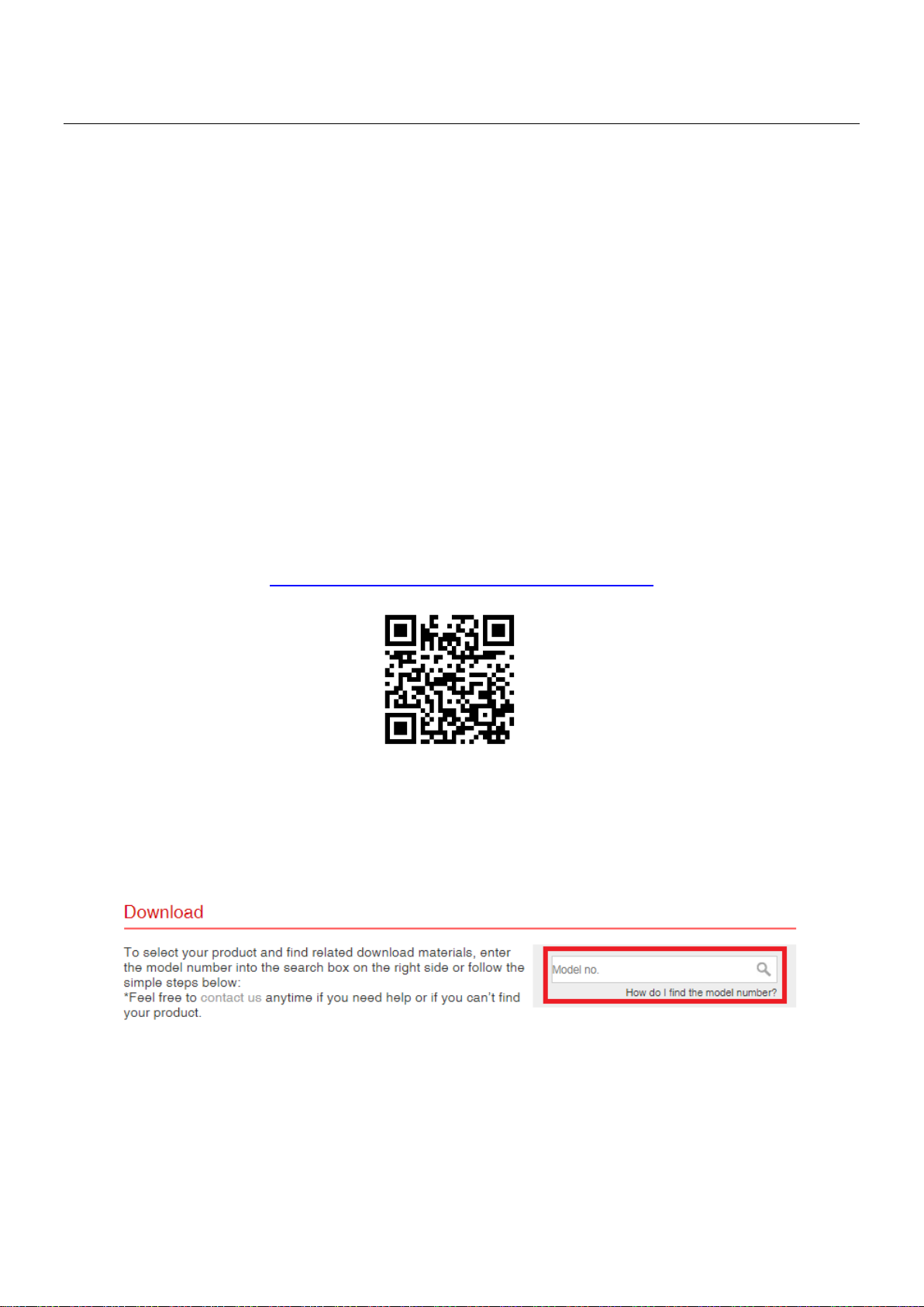
You can find all supporting documents from the link below or via QR Code:
https://www.edimax.com/download
(Once you’ve visited the Edimax official website, please enter model no.
“IGS-1005, IGS-1105P and IGS-1210P” into the search box to search for your
product.)
1
Page 4
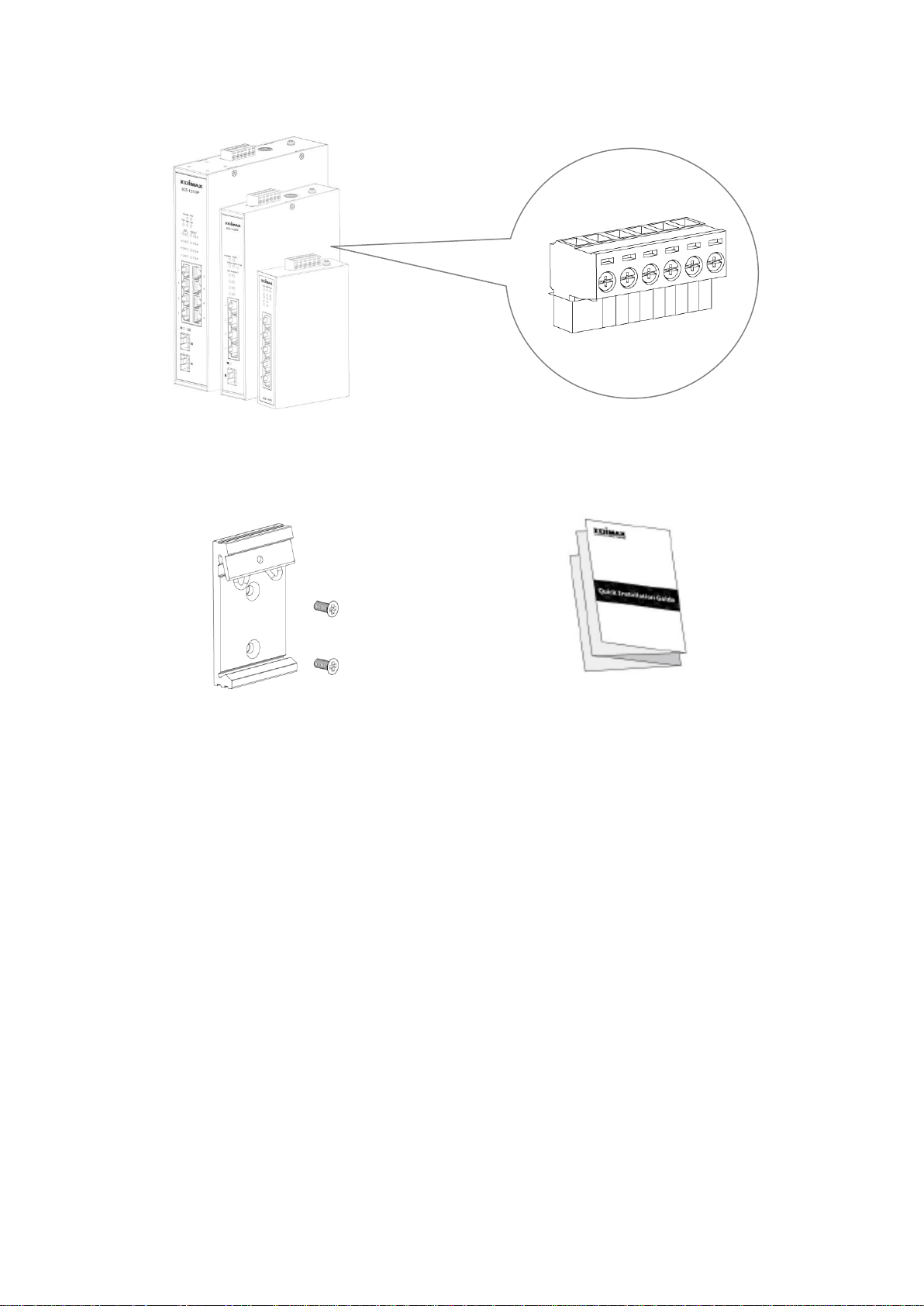
I-1. Package Contents
DC Power Terminal Block
DIN-Rail Mounting Kit
IGS-1005, IGS-1105P or IGS-1210P
Quick Installation Guide
2
Page 5
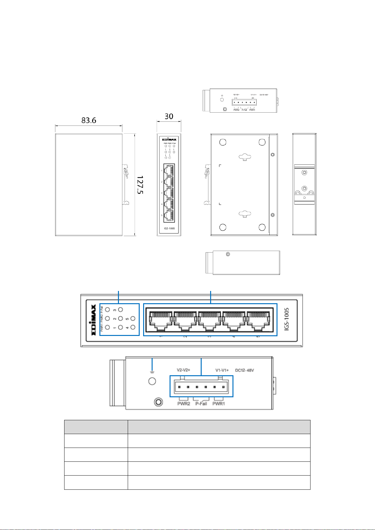
I-2. Hardware Interface
No.
Description
1
LED (PWR1, PWR2, P-Fail, Link/ACT 1~5)
2
LAN Port x 5
3
Grounding Screw
4
Power1/Power2/P-Fail Connector
3
4
1
2
IGS-1005 Dimension: 127.5(H) x 30(W) x 83.6(D) mm
3
Page 6
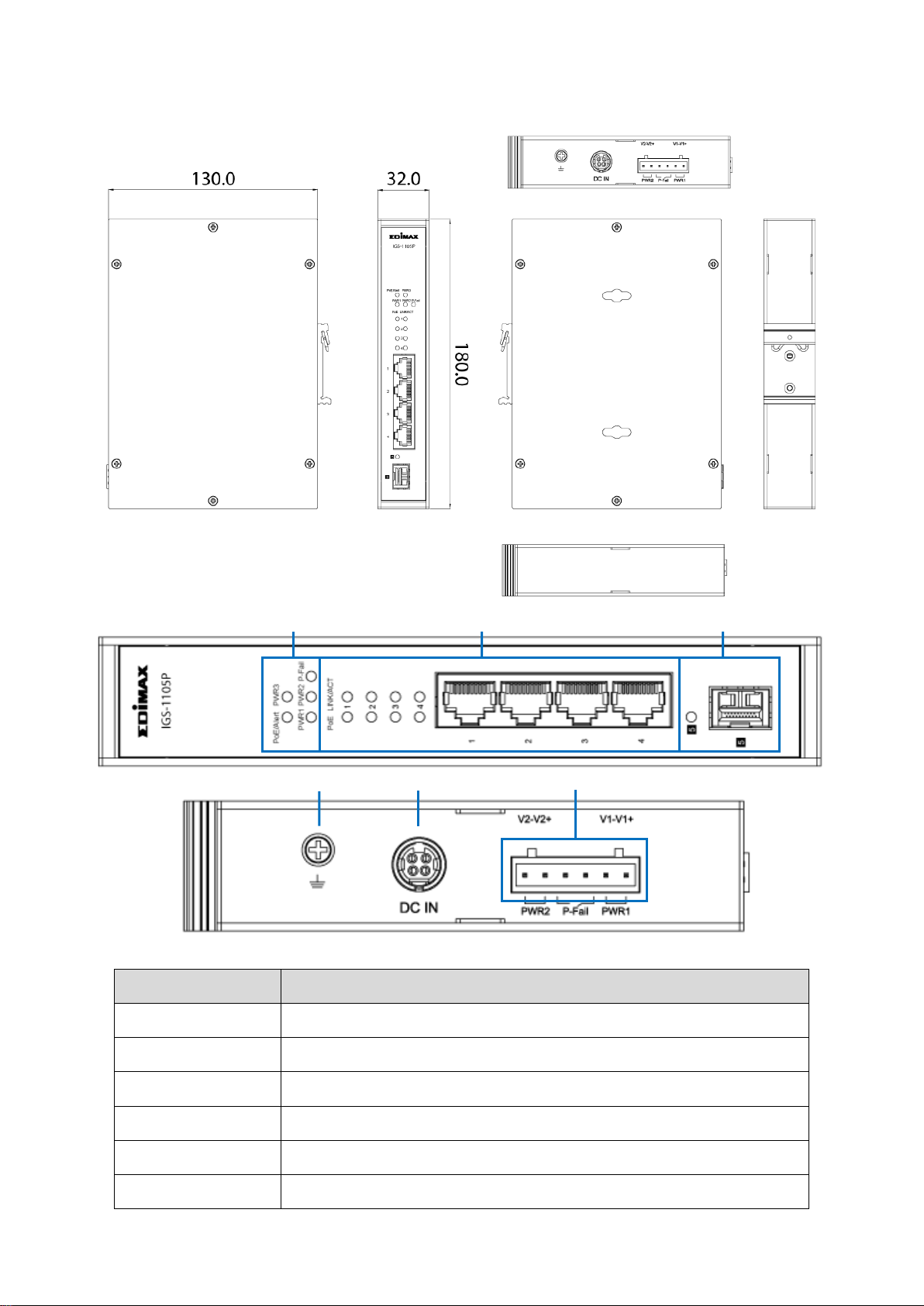
IGS-1105P Dimension: 180(W) x 130(D) x 32(H) mm
No.
Description
1
LED (PoE/Alert, PWR3, PWR1, PWR2, P-Fail)
2
LED (PoE (1~4), LINK/ACT (1~4)), LAN Port x 4
3
LED (Link/ACT (5)), SFP Port x 1
4
Grounding Screw
5
DC In(48-55V) Power Jack
6
Power1/Power2/P-Fail Connector
1 2 3 4 5
6
4
Page 7

IGS-1210P Dimension: 210(H) x 160.6(D) x 46(W) mm
No.
Description
1
LED (PoE/Alert, P-Fail, PWR1, PWR2, PWR3)
2
LED (PoE (1~8), LINK/ACT (1~8)), LAN Port x 8
3
LED (Link/ACT (8~9)), SFP Port x 2
4
Grounding Screw
5
DC In(48-55V) Power Jack
6
Power1/Power2/P-Fail Connector
1
2 3 4 5 6
5
Page 8

I-3. LED Status
LED
Color
Status
Description
P1
(PWR1)
Green
On
The switch is powered by PWR1
Off
PWR1 is disconnected or failed
P2
(PWR2)
Green
On
The system is powered by PWR2
Off
PWR2 is disconnected or failed
P-Fail
Green
On
PWR1 or PWR2 is failed.
Off
The switch is powered by PWR1
and PWR2
Port 1-5
(Link/ACT)
Amber
On
The Port is connected, Link at
10/100M
Flashing
Sending or receiving data
Off
The Port is disconnected or link
failure
Green
On
The Port is connected, Link at
1000M
Flashing
Sending or receiving data
Off
The Port is disconnected or link
failure
IGS-1005
6
Page 9

IGS-1105P & IGS-1210P
LED
Color
Status
Description
PWR1
Green
On
The system is powered by PWR1
Off
PWR1 is disconnected or failed
P2
(PWR2)
Green
On
The switch is powered by PWR2
Off
PWR2 is disconnected or failed
P3
(DC IN)
Green
On
The switch is powered by DC IN
Off
DC IN is disconnected or
failed
P-Fail
Green
On
PWR1 or PWR2 is failed.
Off
The switch is powered by PWR1
and PWR2
PoE/Alert
Green
On
Total PoE power consumed is
exceeding PoE power budget
Off
Total PoE power consumed is
under PoE power budget
PoE
Green
On
Feeding power to PoE devices
Off
PoE function is not active
LINK/ACT
Amber
On
The Port is connected, Link at
10/100M
Flashing
Sending or receiving data
Off
The Port is disconnected or link
failure
Green
On
The Port is connected, Link at
1000M
Flashing
Sending or receiving data
Off
The Port is disconnected or link
failure
SFP Port
Green
On
The Port is connected, Link at
100/1000M
Flashing
Sending or receiving data
Off
The Port is disconnected or link
failure
7
Page 10

II. Installation
1
2
II-1. Mounting the Switch
The industrial switch can be wall-mounted or DIN-Rail mounted. Follow
bellow instruction for DIN-Rail mounting.
1. Attach the DIN-rail mounting bracket to the switch.
2. Follow the steps below to mount the switch on the DIN-Rail track.
8
Page 11

STEP1. Insert the upper end of the DIN-Rail mounting bracket into the
DIN-Rail track from its upper side.
STEP2. Lightly push the bottom of the DIN-Rail mounting bracket into the
track.
STEP3. Check if the DIN-Rail mounting bracket is tightly attached to the
track.
II-2. Powering the Switch
Connect the power source (sold separately) to the switch. Connect the power
adapter to the DC-jack or connect a DIN-Rail power source to the power
terminal block. (Power adapter and DIN-Rail power supply NOT included)
II-2-1. Wiring Power Inputs
IGS-1005/IGS-1105P/IGS-1210P supports power redundancy. If either power
supply fails, the switch will keep operating as usual, and hence guarantees a
constant power source for the system.
The P-Fail relay allows taking precautions against potential power failures.
(DIN Rail power supply NOT included)
1. Insert the Negative / Positive DC wires into the PWR1 (V1-,V1+) terminals
respectively. Tighten the screws to prevent the wires from loosening.
2. Redundant Power: Insert the Negative / Positive DC wires into the PWR2
(V2-,V2+) terminals respectively. Tighten the screws to prevent the wires
from loosening.
9
Page 12

II-2-2. Wiring P-Fail Alarm Device:
Insert the wires (no electrical polarity) into the “P-Fail” terminal block (Fault
Alarm Relay). Tighten the screws to prevent the wires from loosening.
Whenever the “P-Fail” is triggered, it means one of the power supplies is
disconnected or failed.
II-2-3. DC Power Input:
DC Power Input: For IGS-1105P and IGS-1210P ONLY.
DC IN: 48-55VDC, 2A or above
NOTE:
AC to DC power adaptor NOT included.
P-Fail won’t be triggered when “DC IN” is disconnected or failed.
10
Page 13

II-3. Connecting to Network Devices
Connect the switch to end nodes using a standard Cat5e Ethernet cable as
shown in the illustration below and check the LEDs to confirm the connections
are established. The installation procedures have been completed.
11
Page 14

COPYRIGHT
Copyright Edimax Technology Co., Ltd. all rights reserved. No part of this publication
may be reproduced, transmitted, transcribed, stored in a retrieval system, or translated
into any language or computer language, in any form or by any means, electronic,
mechanical, magnetic, optical, chemical, manual or otherwise, without the prior written
permission from Edimax Technology Co., Ltd.
Edimax Technology Co., Ltd. makes no representations or warranties, either expressed or
implied, with respect to the contents hereof and specifically disclaims any warranties,
merchantability, or fitness for any particular purpose. Any software described in this
manual is sold or licensed as is. Should the programs prove defective following their
purchase, the buyer (and not this company, its distributor, or its dealer) assumes the
entire cost of all necessary servicing, repair, and any incidental or consequential damages
resulting from any defect in the software. Edimax Technology Co., Ltd. reserves the right
to revise this publication and to make changes from time to time in the contents hereof
without the obligation to notify any person of such revision or changes.
The product you have purchased and the setup screen may appear slightly different from
those shown in this QIG. The software and specifications are subject to change without
notice. Please visit our website www.edimax.com for updates. All brand and product
names mentioned in this manual are trademarks and/or registered trademarks of their
respective holders.
12
Page 15

Federal Communication Commission Interference Statement
This equipment has been tested and found to comply with the limits for a Class A digital device, pursuant to Part
15 of the FCC Rules. These limits are designed to provide reasonable protection against harmful interference
when the equipment is operated in a commercial environment. This equipment generates, uses, and can radiate
radio frequency energy and, if not installed and used in accordance with the instruction manual, may cause
harmful interference to radio communications. Operation of this equipment in a residential area is likely to cause
harmful interference in which case the user will be required to correct the interference at his own expense.
FCC Radiation Exposure Statement
This device complies with FCC radiation exposure limits set forth for an uncontrolled environment and it also
complies with Part 15 of the FCC RF Rules. This equipment must be installed and operated in accordance with
provided instructions and the antenna(s) used for this transmitter must be installed to provide a separation
distance of at least 20 cm from all persons and must not be co-located or operating in conjunction with any other
antenna or transmitter. End-users and installers must be provided with antenna installation instructions and
consider removing the no-collocation statement.
This device complies with Part 15 of the FCC Rules. Operation is subject to the following two conditions:
(1) this device may not cause harmful interference, and
(2) this device must accept any interference received, including interference that may cause undesired operation.
Caution!
Any changes or modifications not expressly approved by the party responsible for compliance could void the
user's authority to operate the equipment.
R&TTE Compliance Statement
This equipment complies with all the requirements of DIRECTIVE 2014/30/EU OF THE EUROPEAN PARLIAMENT
AND THE COUNCIL of March 9, 1999 on radio equipment and telecommunication terminal equipment and the
mutual recognition of their conformity (R&TTE). The R&TTE Directive repeals and replaces in the directive
98/13/EEC (Telecommunications Terminal Equipment and Satellite Earth Station Equipment) As of April 8, 2000.
Safety
This equipment is designed with the utmost care for the safety of those who install and use it. However, special
attention must be paid to the dangers of electric shock and static electricity when working with electrical
equipment. All guidelines of this and of the computer manufacture must therefore be allowed at all times to
ensure the safe use of the equipment.
EU Countries Intended for Use
The ETSI version of this device is intended for home and office use in Austria, Belgium, Bulgaria, Cyprus, Czech,
Denmark, Estonia, Finland, France, Germany, Greece, Hungary, Ireland, Italy, Latvia, Lithuania, Luxembourg, Malta,
Netherlands, Poland, Portugal, Romania, Slovakia, Slovenia, Spain, Sweden, Turkey, and United Kingdom. The ETSI
version of this device is also authorized for use in EFTA member states: Iceland, Liechtenstein, Norway, and
Switzerland.
EU Countries Not Intended for Use
None
13
Page 16

EU Declaration of Conformity
English: This equipment is in compliance with the essential requirements and other relevant
provisions of Directive 2014/30/EU.
Français: Cet équipement est conforme aux exigences essentielles et autres dispositions de la
directive 2014/30/EU.
Čeština: Toto zařízení je v souladu se základními požadavky a ostatními příslušnými ustanoveními
směrnic 2014/30/EU.
Polski: Urządzenie jest zgodne z ogólnymi wymaganiami oraz szczególnymi warunkami
określonymi Dyrektywą UE 2014/30/EU.
Română: Acest echipament este în conformitate cu cerinţele esenţiale şi alte prevederi relevante ale
Directivei 2014/30/EU.
Русский: Это оборудование соответствует основным требованиям и положениям Директивы
2014/30/EU.
Magyar: Ez a berendezés megfelel az alapvető követelményeknek és más vonatkozó irányelveknek
(2014/30/EU).
Türkçe: Bu cihaz 2014/30/EU. direktifleri zorunlu istekler ve diğer hükümlerle ile uyumludur.
Українська: Обладнання відповідає вимогам і умовам директиви 2014/30/EU.
Slovenčina: Toto zariadenie spĺňa základné požiadavky a ďalšie príslušné ustanovenia smerníc
2014/30/EU.
Deutsch: Dieses Gerät erfüllt die Voraussetzungen gemäß den Richtlinien 2014/30/EU.
Español: El presente equipo cumple los requisitos esenciales de la Directiva 2014/30/EU.
Italiano: Questo apparecchio è conforme ai requisiti essenziali e alle altre disposizioni applicabili
della Direttiva 2014/30/EU.
Nederlands: Dit apparaat voldoet aan de essentiële eisen en andere van toepassing zijnde bepalingen
van richtlijn 2014/30/EU.
Português: Este equipamento cumpre os requesitos essênciais da Directiva 2014/30/EU.
Norsk: Dette utstyret er i samsvar med de viktigste kravene og andre relevante regler i Direktiv
2014/30/EU.
Svenska: Denna utrustning är i överensstämmelse med de väsentliga kraven och övriga relevanta
bestämmelser i direktiv 2014/30/EU.
Dansk: Dette udstyr er i overensstemmelse med de væ sentligste krav og andre relevante
forordninger i direktiv 2014/30/EU.
suomen kieli: Tämä laite täyttää direktiivien 2014/30/EU. oleelliset vaatimukset ja muut asiaankuuluvat
määräykset.
-------------------------------------------------------------------------------------------------------------------
WEEE Directive & Product Disposal
At the end of its serviceable life, this product should not be treated as household or general waste. It
should be handed over to the applicable collection point for the recycling of electrical and electronic
equipment, or returned to the supplier for disposal.
14
Page 17

Declaration of Conformity
We, Edimax Technology Co., Ltd., declare under our sole responsibility, that the
equipment described below complies with the requirements of the European R&TTE
directives.
Equipment:
Industrial 5-Port Gigabit Din-Rail Switch (IGS-1005)
Industrial 5-Port Gigabit PoE+ Din-Rail Switch with 1 SFP (IGS-1105P)
Industrial 10-Port Gigabit PoE+ Din-Rail Switch with 2 SFP (IGS-1210P)
Model No.:
IGS-1005/IGS-1105P/IGS-1210P
The following European standards for essential requirements have been followed:
Directives 2014/30/EU
EMC
:
EN 55032:2015+A11:2020
EN 55035:2017+A11:2020
Directives 2014/35/EU
Safety (LVD)
:
EN 62368-1:2014+A11:2017
Edimax Technology Europe B.V.
Fijenhof 2,
5652 AE Eindhoven,
The Netherlands
a company of:
Edimax Technology Co., Ltd.
No. 278, Xinhu 1st Rd.,
Neihu Dist., Taipei City,
Taiwan
Printed Name:
David Huang
Title:
Director
Edimax Technology Europe B.V.
Date of Signature:
Oct., 2021
Signature:
Printed Name:
Albert Chang
Title:
Director
Edimax Technology Co., Ltd.
15
Page 18

Declaration of Conformity
We, Edimax Technology Co., Ltd., declare under our sole responsibility, that the
equipment described below complies with the requirements of the United Kingdom
EMC and Safety directives.
Equipment:
Industrial 5-Port Gigabit Din-Rail Switch (IGS-1005)
Industrial 5-Port Gigabit PoE+ Din-Rail Switch with 1 SFP (IGS-1105P)
Industrial 10-Port Gigabit PoE+ Din-Rail Switch with 2 SFP (IGS-1210P)
Model No.:
IGS-1005/IGS-1105P/IGS-1210P
The following European standards for essential requirements have been followed:
Electromagnetic Compatibility Regulations 2016 (S.I. 2016/1091)
EMC
:
EN 55032:2015+A11:2020
EN 55035:2017+A11:2020
Electrical Equipment (Safety) Regulations 2016 (S.I. 2016/1101)
Safety (LVD)
:
EN 62368-1:2014+A11:2017
Edimax Technology Europe B.V.
Fijenhof 2,
5652 AE Eindhoven,
The Netherlands
a company of:
Edimax Technology Co., Ltd.
No. 278, Xinhu 1st Rd.,
Neihu Dist., Taipei City,
Taiwan
Printed Name:
David Huang
Title:
Director
Edimax Technology Europe B.V.
Date of Signature:
Oct., 2021
Signature:
Printed Name:
Albert Chang
Title:
Director
Edimax Technology Co., Ltd.
16
 Loading...