

Page 1

IGS-1005/IGS-1105P/IGS-1210P
Schnellinstallationsanleitung
10-2021 / V1.0
1
Page 2

Inhalt
I. Produktinformationen .............................................. 1
I-1. Verpackungsinhalt ..................................................................... 2
I-2. Hardwareschnittstelle ................................................................ 3
I-3. LED Status .................................................................................. 6
II. Installation .............................................................. 8
II-1. Montieren des Switches ............................................................. 8
II-2. Einschalten des Switches ............................................................ 9
II-2-1. Verdrahtung der Stromeingänge ............................................... 9
II-2-2. Verdrahtung der P-Fail Alarmvorrichtung:............................... 10
II-2-3. Gleichstromeingang: ................................................................ 10
II-3. Anschluss an Netzwerkgeräte .................................................... 11
Page 3
I. Produktinformationen
Die Modelle IGS-1005, IGS-1105P und IGS-1210P sind lüfterlos, zur Montage
an eine DIN-Schiene oder Wand geeignet und verfügen über ein
Metallgehäuse. Sie stellen eine einfache Plug-and-Play-Lösung dar, die flexibel
einsetzbar, kostengünstig und energieeffizient ist. Zudem eignen sie sich für
die Erweiterung von Netzwerken und die Erfüllung von Anforderungen an
Datenübertragung und Streaming mit hoher Bandbreite.
Eine ideale Lösung für industrielle Netzwerke in Bereichen wie
Automobilindustrie, Fabrikautomation, Ö l und Gas, Bergbau, Militär,
Transport, Umspannwerke, Energie- und Außenanwendungen von
Eisenbahnen, Straßen, Tunneln, Smart Cities, Stadt- und
Verkehrsüberwachung.
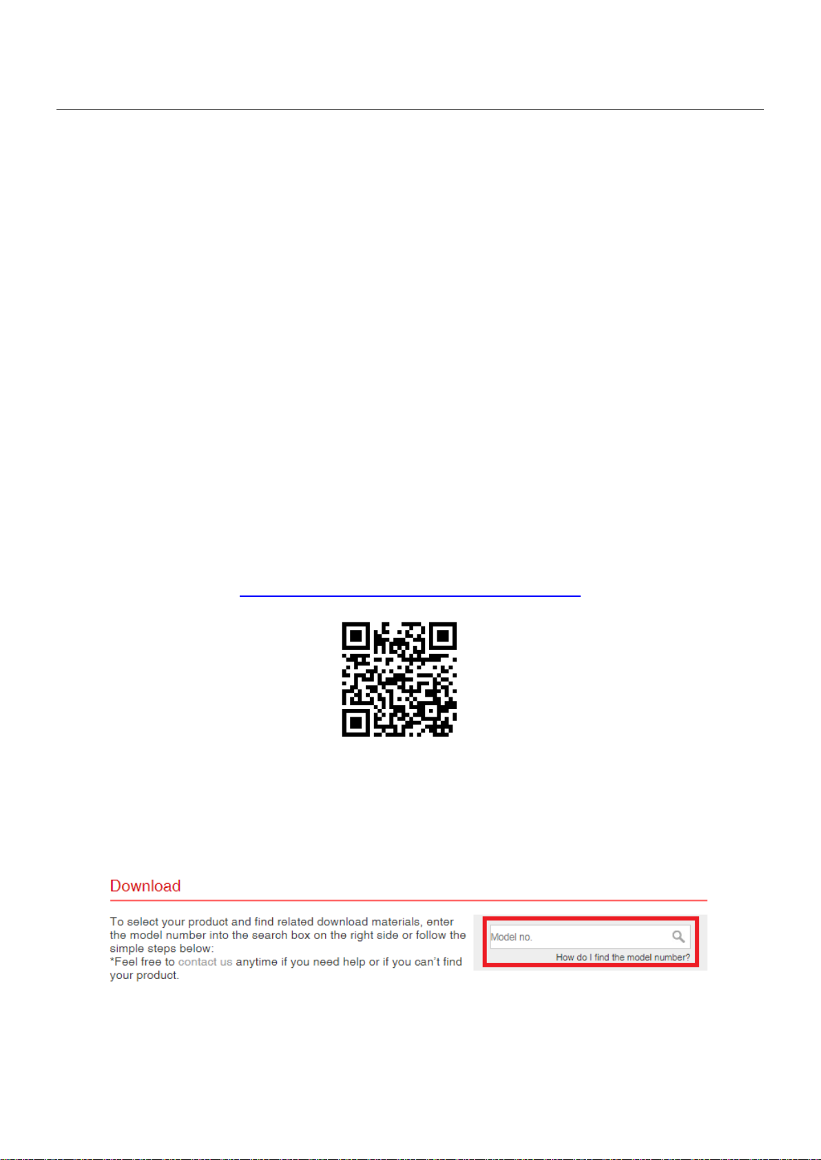
Alle unterstützenden Dokumente finden Sie über den folgenden Link oder den
QR-Code:
https://www.edimax.com/download
(Geben Sie nach Ihrem Besuch der offiziellen Edimax-Website die
Modellnummer „IGS-1005, IGS-1105P und IGS-1210P“ in das Suchfeld ein, um
nach diesem Produkt zu suchen.)
1
Page 4
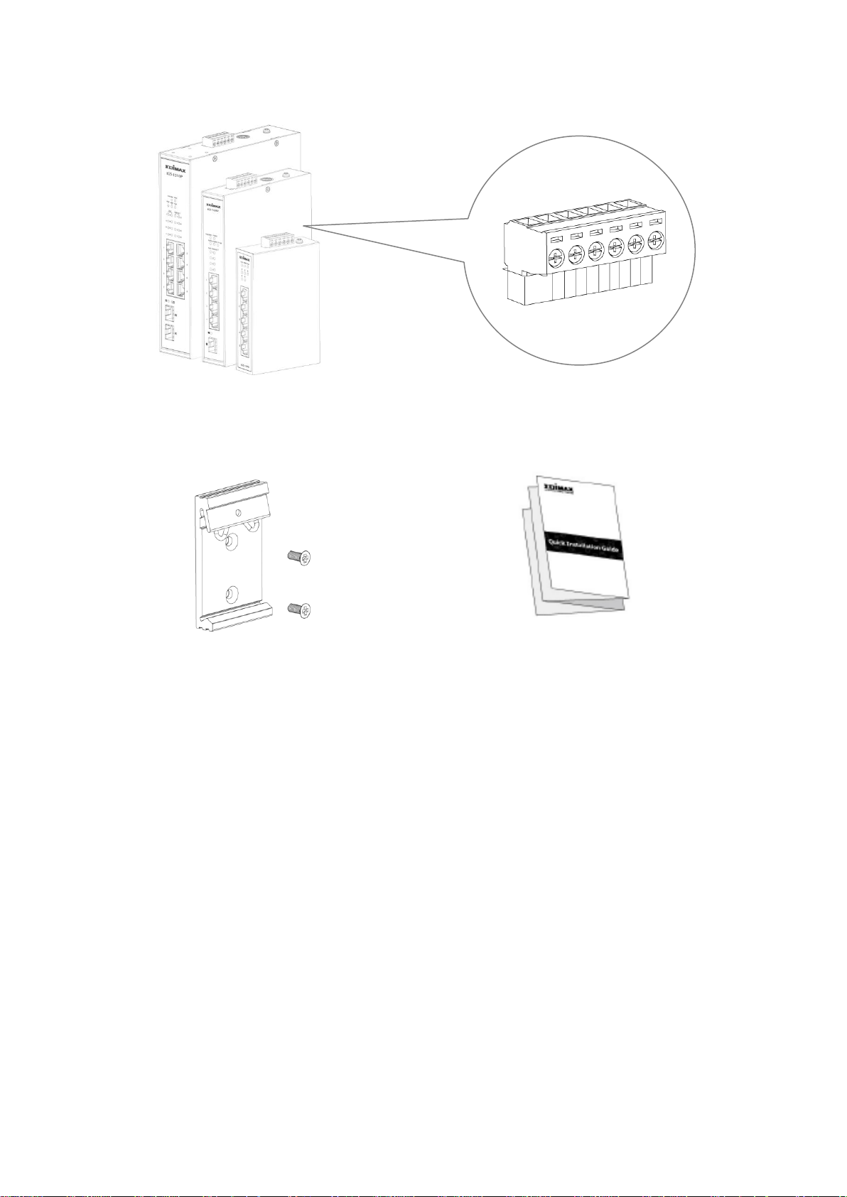
I-1. Verpackungsinhalt
Gleichstromklemmenblock
Montageset für
IGS-1005, IGS-1105P oder IGS-1210P
Schnellinstallationsanlei
2
Page 5
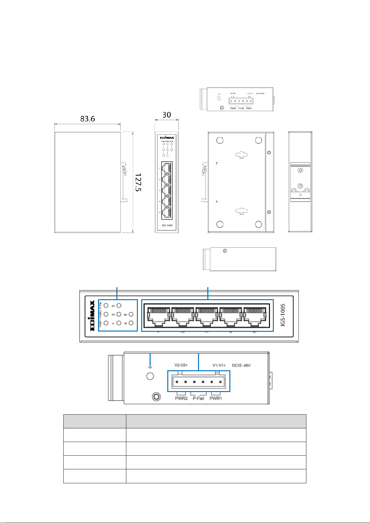
I-2. Hardwareschnittstelle
Nr.
Beschreibung
1
LED (PWR1, PWR2, P-Fail, Link/ACT 1~5)
2
5 LAN-Ports
3
Erdungsschraube
4
Power1/Power2/P-Fail-Anschluss
1
2
3
4
IGS-1005 Maße: 127,5 (H) x 30 (B) x 83,6 (T) mm
3
Page 6
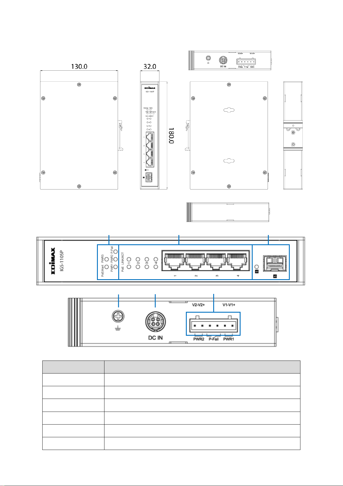
IGS-1105P Maße: 180 (B) x 130 (T) x 32 (H) mm
Nr.
Beschreibung
1
LED (PoE/Alarm, PWR3, PWR1, PWR2, P-Fail)
2
LED (PoE (1~4), LINK/ACT (1~4)), LAN Port x 4
3
LED (Link/ACT (5)), SFP Port x 1
4
Erdungsschraube
5
Netzbuchse DC In (48-55V)
6
Power1/Power2/P-Fail-Anschluss
1 2 3 4 5
6
4
Page 7

IGS-1210P Maße: 210 (H) x 160,6 (T) x 46 (B) mm
Nr.
Beschreibung
1
LED (PoE/Alarm, P-Fail, PWR1, PWR2, PWR3)
2
LED (PoE (1~8), LINK/ACT (1~8)), LAN Port x 8
3
LED (Link/ACT (8~9)), 2 x SFP-Port
4
Erdungsschraube
5
Netzbuchse DC In (48-55V)
6
Power1/Power2/P-Fail-Anschluss
1
2 3 4 5 6
5
Page 8

I-3. LED Status
LED
Farbe
Status
Beschreibung
P1
(PWR1)
Grün
An
Der Switch wird über PWR1
versorgt
Aus
PWR1 ist getrennt oder
ausgefallen
P2
(PWR2)
Grün
An
Das System wird über PWR2
versorgt
Aus
PWR2 ist getrennt oder
ausgefallen
P-Fail
Grün
An
PWR1 oder PWR2 ist
ausgefallen.
Aus
Der Switch wird über PWR1 und
PWR2 versorgt
Port 1-5
(Link/ACT)
Gelb
An
Der Port ist verbunden, Link bei
10/100M
Blinkend
Senden oder Empfangen von
Daten
Aus
Der Port ist getrennt oder
Verbindung fehlgeschlagen
Grün
An
Der Port ist verbunden, Link bei
1000M
Blinkend
Senden oder Empfangen von
Daten
Aus
Der Port ist getrennt oder
Verbindung fehlgeschlagen
IGS-1005
6
Page 9

IGS-1105P & IGS-1210P
LED
Farbe
Status
Beschreibung
(PWR1)
Grün
An
Das System wird über PWR1
versorgt
Aus
PWR1 ist getrennt oder ausgefallen
P2
(PWR2)
Grün
An
Der Switch wird über PWR2
versorgt
Aus
PWR2 ist getrennt oder ausgefallen
P3
(DC IN)
Grün
An
Der Switch wird über DC IN versorgt
Aus
DC IN ist getrennt oder
ausgefallen
P-Fail
Grün
An
PWR1 oder PWR2 ist ausgefallen.
Aus
Der Switch wird über PWR1 und
PWR2 versorgt
PoE/Alarm
Grün
An
Die insgesamt verbrauchte
PoE-Leistung übersteigt das
PoE-Leistungsbudget
Aus
Die insgesamt verbrauchte
PoE-Leistung liegt unter dem
PoE-Leistungsbudget
PoE
Grün
An
Einspeisung von Strom in
PoE-Geräte
Aus
PoE-Funktion ist nicht aktiv
LINK/ACT
Gelb
An
Der Port ist verbunden, Link bei
10/100M
Blinkend
Senden oder Empfangen von Daten
Aus
Der Port ist getrennt oder
Verbindung fehlgeschlagen
Grün
An
Der Port ist verbunden, Link bei
1000M
Blinkend
Senden oder Empfangen von Daten
Aus
Der Port ist getrennt oder
Verbindung fehlgeschlagen
SFP-Port
Grün
An
Der Port ist verbunden, Link bei
100/1000M
Blinkend
Senden oder Empfangen von Daten
Aus
Der Port ist getrennt oder
Verbindung fehlgeschlagen
7
Page 10

II. Installation
1
2
II-1. Montieren des Switches
Der Industrie-Switch kann an der Wand oder an einer DIN-Schiene montiert
werden. Befolgen Sie die nachstehenden Anweisungen für die
DIN-Schienen-Montage.
1. Befestigen Sie die DIN-Schienenhalterung am Switch.
2. Gehen Sie wie folgt vor, um den Switch an der DIN-Schiene zu montieren.
8
Page 11

SCHRITT 1. Setzen Sie das obere Ende des DIN-Schienenhalterung von
oben in die Rückseite der DIN-Schiene ein.
SCHRITT 2. Drücken Sie das Unterteil der DIN-Schienenhalterung leicht in
die Schiene hinein.
SCHRITT 3. Ü berprüfen Sie, ob die DIN-Schienenhalterung fest an der
Schiene sitzt.
II-2. Einschalten des Switches
Schließen Sie das Netzteil (separat erhältlich) an den Switch an. Schließen Sie
den Netzadapter an die Gleichstrombuchse an oder verbinden Sie ein
DIN-Schienen-Netzteil mit dem Klemmenblock. (Netzadapter und
DIN-Schienen-Netzteil NICHT enthalten)
II-2-1. Verdrahtung der Stromeingänge
IGS-1005/IGS-1105P/IGS-1210P unterstützt Stromredundanz. Fällt eine der
Stromversorgungen aus, arbeitet der Switch wie gewohnt weiter und
gewährleistet somit die konstante Stromversorgung des Systems.
Mit Hilfe des P-Fail-Relais können Vorkehrungen gegen mögliche
Stromausfälle getroffen werden. (DIN-Schienen-Netzteil NICHT enthalten)
1. Stecken Sie die negativen bzw. positiven Gleichstromdrähte in die
Klemmen PWR1 (V1-, V1+). Ziehen Sie die Schrauben an, damit sich die
Drähte nicht lösen können.
2. Stromredundanz: Stecken Sie die negativen bzw. positiven
Gleichstromdrähte in die Klemmen PWR2 (V2-, V2+). Ziehen Sie die
Schrauben an, damit sich die Drähte nicht lösen können.
9
Page 12

II-2-2. Verdrahtung der P-Fail Alarmvorrichtung:
Stecken Sie die Drähte (ohne elektrische Polarität) in die Klemmenleiste
„P-Fail“ (Störungsalarmrelais). Ziehen Sie die Schrauben an, damit sich die
Drähte nicht lösen können.
Sobald „P-Fail“ ausgelöst wird, bedeutet dies, dass eines der Netzteile nicht
angeschlossen oder ausgefallen ist.
II-2-3. Gleichstromeingang:
Gleichstromeingang: NUR für IGS-1105P und IGS-1210P.
DC IN: 48-55VDC, 2A oder höher
HINWEIS:
AC-zu-DC-Netzadapter NICHT enthalten.
P-Fail wird nicht ausgelöst, wenn „DC IN“ unterbrochen oder ausgefallen
ist.
10
Page 13

II-3. Anschluss an Netzwerkgeräte
Schließen Sie den Switch wie unten gezeigt mit einem
Standard-Cat5e-Ethernet-Kabel an die Endknoten an und überprüfen Sie die
LEDs dahingehend, ob die Verbindungen hergestellt sind. Damit sind die
Installationsschritte abgeschlossen.
11
Page 14

COPYRIGHT
Copyright Edimax Technology Co., Ltd. all rights reserved. No part of this publication
may be reproduced, transmitted, transcribed, stored in a retrieval system, or translated
into any language or computer language, in any form or by any means, electronic,
mechanical, magnetic, optical, chemical, manual or otherwise, without the prior written
permission from Edimax Technology Co., Ltd.
Edimax Technology Co., Ltd. makes no representations or warranties, either expressed or
implied, with respect to the contents hereof and specifically disclaims any warranties,
merchantability, or fitness for any particular purpose. Any software described in this
manual is sold or licensed as is. Should the programs prove defective following their
purchase, the buyer (and not this company, its distributor, or its dealer) assumes the
entire cost of all necessary servicing, repair, and any incidental or consequential damages
resulting from any defect in the software. Edimax Technology Co., Ltd. reserves the right
to revise this publication and to make changes from time to time in the contents hereof
without the obligation to notify any person of such revision or changes.
The product you have purchased and the setup screen may appear slightly different from
those shown in this QIG. The software and specifications are subject to change without
notice. Please visit our website www.edimax.com for updates. All brand and product
names mentioned in this manual are trademarks and/or registered trademarks of their
respective holders.
12
Page 15

Federal Communication Commission Interference Statement
This equipment has been tested and found to comply with the limits for a Class A digital device, pursuant to Part
15 of the FCC Rules. These limits are designed to provide reasonable protection against harmful interference
when the equipment is operated in a commercial environment. This equipment generates, uses, and can radiate
radio frequency energy and, if not installed and used in accordance with the instruction manual, may cause
harmful interference to radio communications. Operation of this equipment in a residential area is likely to cause
harmful interference in which case the user will be required to correct the interference at his own expense.
FCC Radiation Exposure Statement
This device complies with FCC radiation exposure limits set forth for an uncontrolled environment and it also
complies with Part 15 of the FCC RF Rules. This equipment must be installed and operated in accordance with
provided instructions and the antenna(s) used for this transmitter must be installed to provide a separation
distance of at least 20 cm from all persons and must not be co-located or operating in conjunction with any other
antenna or transmitter. End-users and installers must be provided with antenna installation instructions and
consider removing the no-collocation statement.
This device complies with Part 15 of the FCC Rules. Operation is subject to the following two conditions:
(1) this device may not cause harmful interference, and
(2) this device must accept any interference received, including interference that may cause undesired operation.
Caution!
Any changes or modifications not expressly approved by the party responsible for compliance could void the
user's authority to operate the equipment.
R&TTE Compliance Statement
This equipment complies with all the requirements of DIRECTIVE 2014/30/EU OF THE EUROPEAN PARLIAMENT
AND THE COUNCIL of March 9, 1999 on radio equipment and telecommunication terminal equipment and the
mutual recognition of their conformity (R&TTE). The R&TTE Directive repeals and replaces in the directive
98/13/EEC (Telecommunications Terminal Equipment and Satellite Earth Station Equipment) As of April 8, 2000.
Safety
This equipment is designed with the utmost care for the safety of those who install and use it. However, special
attention must be paid to the dangers of electric shock and static electricity when working with electrical
equipment. All guidelines of this and of the computer manufacture must therefore be allowed at all times to
ensure the safe use of the equipment.
EU Countries Intended for Use
The ETSI version of this device is intended for home and office use in Austria, Belgium, Bulgaria, Cyprus, Czech,
Denmark, Estonia, Finland, France, Germany, Greece, Hungary, Ireland, Italy, Latvia, Lithuania, Luxembourg, Malta,
Netherlands, Poland, Portugal, Romania, Slovakia, Slovenia, Spain, Sweden, Turkey, and United Kingdom. The ETSI
version of this device is also authorized for use in EFTA member states: Iceland, Liechtenstein, Norway, and
Switzerland.
EU Countries Not Intended for Use
None
13
Page 16

EU Declaration of Conformity
English: This equipment is in compliance with the essential requirements and other relevant
provisions of Directive 2014/30/EU.
Français: Cet équipement est conforme aux exigences essentielles et autres dispositions de la
directive 2014/30/EU.
Čeština: Toto zařízení je v souladu se základními požadavky a ostatními příslušnými ustanoveními
směrnic 2014/30/EU.
Polski: Urządzenie jest zgodne z ogólnymi wymaganiami oraz szczególnymi warunkami
określonymi Dyrektywą UE 2014/30/EU.
Română: Acest echipament este în conformitate cu cerinţele esenţiale şi alte prevederi relevante ale
Directivei 2014/30/EU.
Русский: Это оборудование соответствует основным требованиям и положениям Директивы
2014/30/EU.
Magyar: Ez a berendezés megfelel az alapvető követelményeknek és más vonatkozó irányelveknek
(2014/30/EU).
Türkçe: Bu cihaz 2014/30/EU. direktifleri zorunlu istekler ve diğer hükümlerle ile uyumludur.
Українська: Обладнання відповідає вимогам і умовам директиви 2014/30/EU.
Slovenčina: Toto zariadenie spĺňa základné požiadavky a ďalšie príslušné ustanovenia smerníc
2014/30/EU.
Deutsch: Dieses Gerät erfüllt die Voraussetzungen gemäß den Richtlinien 2014/30/EU.
Español: El presente equipo cumple los requisitos esenciales de la Directiva 2014/30/EU.
Italiano: Questo apparecchio è conforme ai requisiti essenziali e alle altre disposizioni applicabili
della Direttiva 2014/30/EU.
Nederlands: Dit apparaat voldoet aan de essentiële eisen en andere van toepassing zijnde bepalingen
van richtlijn 2014/30/EU.
Português: Este equipamento cumpre os requesitos essênciais da Directiva 2014/30/EU.
Norsk: Dette utstyret er i samsvar med de viktigste kravene og andre relevante regler i Direktiv
2014/30/EU.
Svenska: Denna utrustning är i överensstämmelse med de väsentliga kraven och övriga relevanta
bestämmelser i direktiv 2014/30/EU.
Dansk: Dette udstyr er i overensstemmelse med de væ sentligste krav og andre relevante
forordninger i direktiv 2014/30/EU.
suomen kieli: Tämä laite täyttää direktiivien 2014/30/EU. oleelliset vaatimukset ja muut asiaankuuluvat
määräykset.
-------------------------------------------------------------------------------------------------------------------
WEEE Directive & Product Disposal
At the end of its serviceable life, this product should not be treated as household or general waste. It
should be handed over to the applicable collection point for the recycling of electrical and electronic
equipment, or returned to the supplier for disposal.
14
Page 17

Declaration of Conformity
We, Edimax Technology Co., Ltd., declare under our sole responsibility, that the
equipment described below complies with the requirements of the European R&TTE
directives.
Equipment:
Industrial 5-Port Gigabit Din-Rail Switch (IGS-1005)
Industrial 5-Port Gigabit PoE+ Din-Rail Switch with 1 SFP (IGS-1105P)
Industrial 10-Port Gigabit PoE+ Din-Rail Switch with 2 SFP (IGS-1210P)
Model No.:
IGS-1005/IGS-1105P/IGS-1210P
The following European standards for essential requirements have been followed:
Directives 2014/30/EU
EMC
:
EN 55032:2015+A11:2020
EN 55035:2017+A11:2020
Directives 2014/35/EU
Safety (LVD)
:
EN 62368-1:2014+A11:2017
Edimax Technology Europe B.V.
Fijenhof 2,
5652 AE Eindhoven,
The Netherlands
a company of:
Edimax Technology Co., Ltd.
No. 278, Xinhu 1st Rd.,
Neihu Dist., Taipei City,
Taiwan
Printed Name:
David Huang
Title:
Director
Edimax Technology Europe B.V.
Date of Signature:
Oct., 2021
Signature:
Printed Name:
Albert Chang
Title:
Director
Edimax Technology Co., Ltd.
15
Page 18

Declaration of Conformity
We, Edimax Technology Co., Ltd., declare under our sole responsibility, that the
equipment described below complies with the requirements of the United Kingdom
EMC and Safety directives.
Equipment:
Industrial 5-Port Gigabit Din-Rail Switch (IGS-1005)
Industrial 5-Port Gigabit PoE+ Din-Rail Switch with 1 SFP (IGS-1105P)
Industrial 10-Port Gigabit PoE+ Din-Rail Switch with 2 SFP (IGS-1210P)
Model No.:
IGS-1005/IGS-1105P/IGS-1210P
The following European standards for essential requirements have been followed:
Electromagnetic Compatibility Regulations 2016 (S.I. 2016/1091)
EMC
:
EN 55032:2015+A11:2020
EN 55035:2017+A11:2020
Electrical Equipment (Safety) Regulations 2016 (S.I. 2016/1101)
Safety (LVD)
:
EN 62368-1:2014+A11:2017
Edimax Technology Europe B.V.
Fijenhof 2,
5652 AE Eindhoven,
The Netherlands
a company of:
Edimax Technology Co., Ltd.
No. 278, Xinhu 1st Rd.,
Neihu Dist., Taipei City,
Taiwan
Printed Name:
David Huang
Title:
Director
Edimax Technology Europe B.V.
Date of Signature:
Oct., 2021
Signature:
Printed Name:
Albert Chang
Title:
Director
Edimax Technology Co., Ltd.
16
 Loading...