

Page 1

GS-5424PLC V2/ GS-5216PLC/GS-5210PL
User Manual
08-2021 / v1.1
Page 2

Contents
I. Product Information .............................................................................. 1
I-1. Package Contents ...................................................................... 2
I-2. Hardware Overview ................................................................... 2
I-3. LED Status .................................................................................. 4
II. Getting Started the Configuration Utility ............................................... 6
III. Web-based Switch Configuration ........................................................... 8
III-1. Status ......................................................................................... 8
III-1-1. System Information ............................................................................ 8
III-1-2. Logging Message ............................................................................... 10
III-1-3. Port ................................................................................................... 11
III-1-3-1. Statistics ............................................................................................ 11
III-1-3-2. Error Disabled ................................................................................... 14
III-1-3-3. Bandwidth Utilization ........................................................................ 14
III-1-4. Link Aggregation ............................................................................... 15
III-1-5. MAC Address Table ........................................................................... 16
III-2. Network ................................................................................... 17
III-2-1. IP Address ......................................................................................... 17
III-2-2. System Time ..................................................................................... 19
III-3. Port .......................................................................................... 22
III-3-1. Port Setting ....................................................................................... 22
III-3-2. Long Range Mode ............................................................................. 24
III-3-3. Error Disable ..................................................................................... 25
III-3-4. Link Aggregation ............................................................................... 26
III-3-4-1. Group ................................................................................................ 26
III-3-4-2. Port Setting ....................................................................................... 28
III-3-4-3. LACP .................................................................................................. 30
III-3-4-4. EEE .................................................................................................... 31
III-3-5. Jumbo Frame .................................................................................... 32
III-4. PoE ........................................................................................... 32
Page 3

III-4-1. Global Setting ................................................................................... 33
III-4-2. PoE On/Off ........................................................................................ 35
III-4-3. PD Alive Check .................................................................................. 36
III-5. VLAN ........................................................................................ 37
III-5-1. VLAN ................................................................................................. 37
III-5-1-1. Create VLAN ...................................................................................... 37
III-5-1-2. VLAN Configuration ........................................................................... 39
III-5-1-3. Membership ...................................................................................... 40
III-5-1-4. Port Setting ....................................................................................... 42
III-5-2. Voice VLAN ....................................................................................... 43
III-5-2-1. Property ............................................................................................ 44
III-5-2-2. Voice OUI .......................................................................................... 45
III-5-3. MAC VLAN ........................................................................................ 47
III-5-3-1. MAC Group ....................................................................................... 47
III-5-3-2. Group Binding ................................................................................... 48
III-5-4. Surveillance VLAN ............................................................................. 49
III-5-4-1. Property ............................................................................................ 50
III-5-4-2. Surveillance OUI ................................................................................ 51
III-6. MAC Address Table .................................................................. 51
III-6-1. Dynamic Address .............................................................................. 52
III-6-2. Static Address ................................................................................... 52
III-6-3. Filtering Address ............................................................................... 53
III-7. Spanning Tree .......................................................................... 53
III-7-1. Property ............................................................................................ 53
III-7-2. Port Setting ....................................................................................... 56
III-7-3. MST Instance .................................................................................... 58
III-7-4. MST Port Setting ............................................................................... 60
III-7-5. Statistics ........................................................................................... 62
III-8. Discovery ................................................................................. 63
III-8-1. LLDP .................................................................................................. 63
III-8-1-1. Property ............................................................................................ 64
III-8-1-2. Port Setting ....................................................................................... 65
III-8-1-3. Packet View ....................................................................................... 67
III-8-1-4. Local Information .............................................................................. 70
III-8-1-5. Neighbor ........................................................................................... 72
III-8-1-6. Statistics ............................................................................................ 76
Page 4

III-9. Multicast .................................................................................. 77
III-9-1. General ............................................................................................. 77
III-9-1-1. Property ............................................................................................ 77
III-9-1-2. Group Address .................................................................................. 78
III-9-1-3. Router Port ....................................................................................... 80
III-9-2. IGMP Snooping ................................................................................. 82
III-9-2-1. Property ............................................................................................ 82
III-9-2-2. Querier .............................................................................................. 85
III-9-2-3. Statistics ............................................................................................ 87
III-9-3. MVR .................................................................................................. 88
III-9-3-1. Property ............................................................................................ 88
III-9-3-2. Port Setting ....................................................................................... 89
III-9-3-3. Group Address .................................................................................. 90
III-10. Security .................................................................................... 92
III-10-1. RADIUS ............................................................................................. 92
III-10-2. Management Access ......................................................................... 95
III-10-2-1. Management VLAN ........................................................................... 95
III-10-2-2. Management Service ........................................................................ 95
III-10-2-3. Management ACL .............................................................................. 97
III-10-2-4. Management ACE ............................................................................. 98
III-10-3. Authentication Manager ................................................................. 101
III-10-3-1. Property .......................................................................................... 101
III-10-3-2. Port Setting ..................................................................................... 106
III-10-3-3. Sessions .......................................................................................... 109
III-10-4. Port Security ................................................................................... 111
III-10-5. Traffic Segmentation....................................................................... 112
III-10-6. Storm Control ................................................................................. 114
III-10-7. DoS ................................................................................................. 116
III-10-7-1. Property .......................................................................................... 116
III-10-7-2. Port Setting ..................................................................................... 118
III-10-8. DHCP Snooping ............................................................................... 119
III-10-8-1. Property .......................................................................................... 120
III-10-8-2. Statistics .......................................................................................... 122
III-10-8-3. Option82 Property .......................................................................... 123
III-10-8-4. Option82 Circuit ID .......................................................................... 125
III-10-9. IP Source Guard .............................................................................. 126
III-10-9-1. Port Setting ..................................................................................... 126
III-10-9-2. IMPV Binding................................................................................... 127
III-10-9-3. Save Database ................................................................................. 129
Page 5

III-11. ACL ......................................................................................... 130
III-11-1. MAC ACL ......................................................................................... 130
III-11-2. MAC ACE ......................................................................................... 131
III-11-3. IPv4 ACL .......................................................................................... 133
III-11-4. IPv4 ACE .......................................................................................... 134
III-11-5. ACL Binding ..................................................................................... 137
III-12. QoS ........................................................................................ 138
III-12-1. General ........................................................................................... 138
III-12-1-1. Property .......................................................................................... 139
III-12-1-2. Queue Scheduling ........................................................................... 141
III-12-1-3. CoS Mapping ................................................................................... 142
III-12-1-4. IP Precedence Mapping................................................................... 143
III-12-2. Rate Limit ........................................................................................ 144
III-12-2-1. Ingress/Egress Port ......................................................................... 144
III-13. Diagnostics ............................................................................ 145
III-13-1. Logging ........................................................................................... 146
III-13-1-1. Property .......................................................................................... 146
III-13-1-2. Remote Server ................................................................................ 147
III-13-2. Mirroring ........................................................................................ 148
III-13-3. Ping ................................................................................................. 150
III-13-4. Traceroute ...................................................................................... 151
III-13-5. Copper Test .................................................................................... 152
III-13-6. Fiber Module .................................................................................. 153
III-13-7. UDLD ............................................................................................... 154
III-13-7-1. Property .......................................................................................... 154
III-13-7-2. Neighbor ......................................................................................... 156
III-14. Management ......................................................................... 157
III-14-1. User Account .................................................................................. 157
III-14-2. Fireware .......................................................................................... 159
III-14-2-1. Upgrade / Backup ........................................................................... 159
III-14-2-2. Active Image ................................................................................... 163
III-14-3. Configuration .................................................................................. 164
III-14-3-1. Upgrade / Backup ........................................................................... 164
III-14-3-2. Save Configuration .......................................................................... 168
III-14-4. SNMP .............................................................................................. 168
III-14-4-1. View ................................................................................................ 168
III-14-4-2. Group .............................................................................................. 169
Page 6

III-14-4-3. Community ..................................................................................... 171
III-14-4-4. User ................................................................................................ 173
III-14-4-5. Engine ID ......................................................................................... 176
III-14-4-6. Trap Event ....................................................................................... 178
III-14-4-7. Notification ..................................................................................... 178
III-14-5. Time Range ..................................................................................... 182
IV. Surveillance Mode .............................................................................. 183
IV-1. Home Page ............................................................................ 183
IV-1-1. Overview......................................................................................... 184
IV-1-2. Port Info .......................................................................................... 185
IV-1-3. IP Camera Info ................................................................................ 186
IV-1-4. NVR Info .......................................................................................... 187
IV-1-5. PoE Info .......................................................................................... 187
IV-1-6. Status .............................................................................................. 188
IV-2. PoE Scheduling ...................................................................... 189
IV-3. Time ....................................................................................... 191
IV-3-1. Clock Settings .................................................................................. 191
IV-3-2. SNTP Settings .................................................................................. 192
IV-4. Surveillance Settings .............................................................. 193
IV-5. Mail Alert ............................................................................... 196
IV-6. Powered Device Monitor ....................................................... 198
IV-7. ONVIF .................................................................................... 200
IV-7-1. IPC Discover .................................................................................... 200
IV-7-2. NVR Discover .................................................................................. 200
IV-8. E-map Management .............................................................. 201
IV-8-1. Image Upload .................................................................................. 201
IV-8-2. Image Settings ................................................................................ 202
IV-8-3. E-map View ..................................................................................... 203
IV-9. Tools ...................................................................................... 203
IV-9-1. Firmware Information ..................................................................... 203
IV-9-2. Firmware Upgrade & Backup .......................................................... 204
Page 7

IV-9-3. Configuration Restore & Backup ..................................................... 204
IV-9-4. Reset ............................................................................................... 205
IV-9-5. Reboot System ................................................................................ 205
V. Config Reload Button(Firmware version V1.0.8) .................................. 206
V-1. ONVIF Compliant Devices Enrollment (Standard Mode) ....... 208
V-2. Non-ONVIF Compliant Devices Enrollment (Standard Mode) 208
V-3. ONVIF Compliant Devices Enrollment (Surveillance Mode) ... 210
V-4. Non-ONVIF Compliant Devices Enrollment (Surveillance Mode) . 210
Page 8

I. Product Information
The EDIMAX Pro GS-5424PLC V2/ GS-5216PLC/GS-5210PL Surveillance VLAN
Long-range PoE+ Web-Smart Switches come with a web-based user interface,
The Gigabit connectivity fully utilizes the power of your office networking for
demanding tasks, such as data backup, video conferencing, IP surveillance,
high volume transaction processing, large file transferring, and more. EDIMAX
Surveillance VLAN Long-range PoE Web-Smart Switches Support ONVIF Profile
Q standard which is compatible with working ONVIF compliant Profiles
G/Q/S/A/C/T/M devices to provide fast and easy system settings, device
discovery, and use authentication.
You can find all supporting documents from the link below or via QR Code:
https://www.edimax.com/download
(Once you’ve visited the Edimax official website, please enter the model #.
into the search box to search for your product.)
1
Page 9

I-1. Package Contents
Model#
Surveillance
VAN
Web-Smart
Switch
Quick
Installatio
n Guide
Rack-Mount
Kit
Power
Cord
Console
Cable
GS-5424PLC V2
V V V V V
GS-5216PLC
V V V V
GS-5210PL
V V V V
1 2 3 4 5 6 7
8
Before start using this product, please check if there is anything missing in the
package, and contact your dealer to claim the missing item(s):
I-2. Hardware Overview
GS-5424PLC V2:
2
Page 10
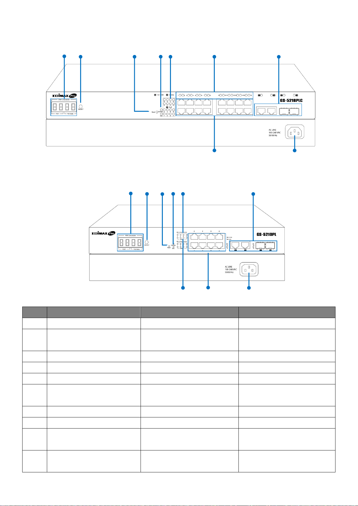
GS-5216PLC:
No.
GS-5424PLC V2
GS-5216PLC
GS-5210PL
1.
Reset Button
Reset Button
Reset Button
2.
LED (PoE/Alert, SYS
PWR)
LED (PoE/Alert, PWR)
LED (PoE/Alert, SYS)
3.
LED PoE
LED PoE
LED Link/Act
4.
LED Link/Act
LED Link/Act
LED PoE
5.
PoE Port 1~24
PoE Port 1~16
PoE Port 1~8
6.
Combo Ports
(RJ45/SFP) 25~28
Combo Ports
(RJ45/SFP) 17~18
RJ45 Port 9~10
SFP Port 11~12
7.
Console Port
N/A
N/A
8.
Power Socket
Power Socket
Power Socket
9.
N/A
PWR Consumption:
PORT, PoE Watts
PWR Consumption:
PORT, PoE Watts
10.
Selection Button
PWR Consumption
Status SELECT Button
PWR Consumption
Status SELECT Button
1
2
3
4
5 6 8
9
10
1 2 3 4 5 6 8 9 10
GS-5210PL:
3
Page 11
I-3. LED Status
Function
Status
Description
Data Rate:
10/100/1000M
On (Amber)
Port is connected, Link at 10/100M
On (Green)
Port is connected, Link at 1000M
Off
Port is disconnected or link failure
Flashing
(Amber or Green)
Sending or receiving data
PoE
On
Feeding power to PoE devices
Off
PoE function is not active
SFP
On (Green)
Port is connected, Link at 1000M
On (Amber)
Port is connected, Link at 100M
Flashing
(Amber or Green)
Sending or receiving data
PoE/Alert
On
Total PoE power consumed is
exceeding PoE power budget
Off
Total PoE power consumed is under
PoE power budget
SYS PWR
On (Green)
System Power on
Off
System Power off
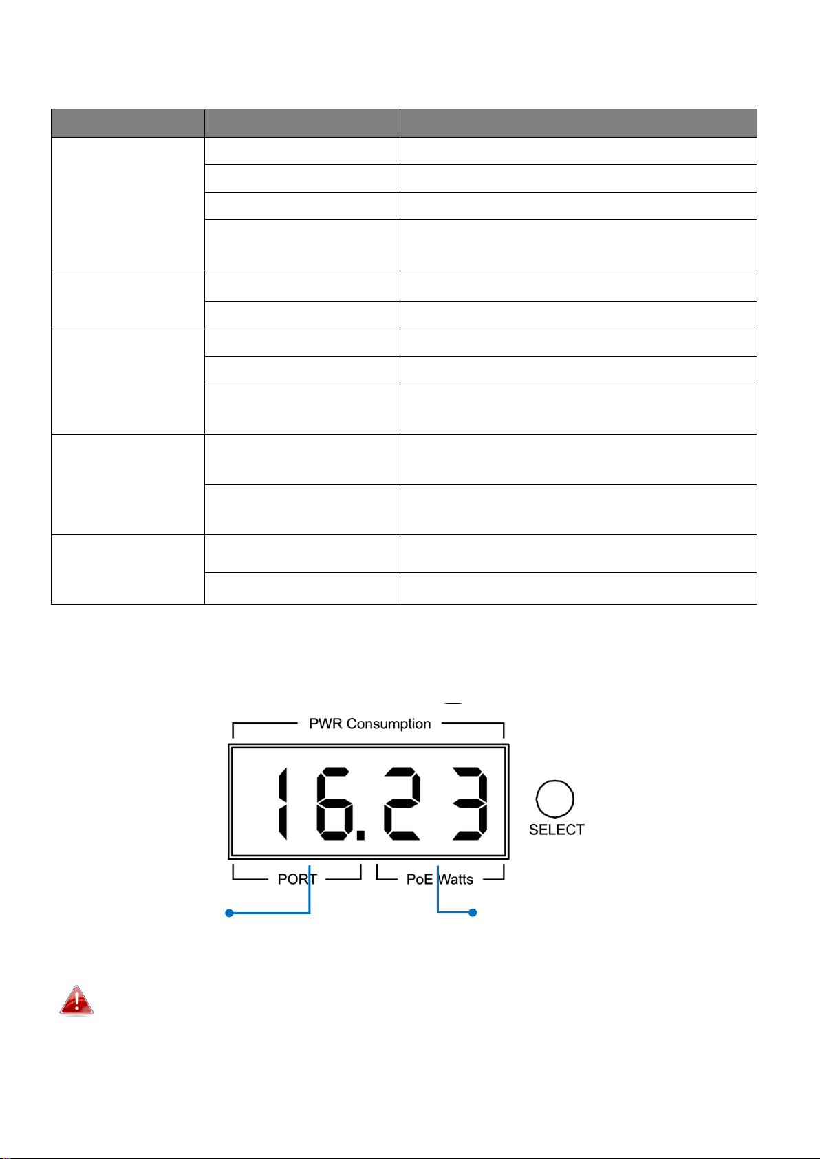
Port #
PoE Power Consumption
(Watts) of the Port
7-Segment LED Power Consumption Status
(GS-5216PLC & GS-5210PL ONLY)
Note: The LED indicator shows you the status of “Total PoE Power Budget” or
“PoE Power Budget Left” when only 3 LED indicators are lighted on
4
Page 12

NOTE:
Please press the “Selection Button” to change the power LED status
indicator.
- Without pressing the selection button:
The LED status indicator shows the total power budget.
- Press the selection button twice:
The LED status indicator shows the total power budget left.
If you want to see power consumption of each port, each time the button is
pressed, the power consumption is displayed as follows.
5
Page 13

II. Getting Started the Configuration Utility
This section describes how to navigate the web-based switch configuration
utility. Be sure to disable any pop-up blocker.
Launching the Configuration Utility:
To open the web-based configuration utility:
1. Open a Web browser.
2. Enter the IP address of the device you are configuring in the address bar on
the browser (factory default IP address is 192.168.2.1) and then press
Enter.
3. The default username is admin and the default password is 1234.
6
Page 14

4. The first time that you log in with the default username and password,
you are required to enter a New Password and Confirm Password
5. For more information about Web-based Configuration Utility, please
download User Manual from EDIMAX Download Center:
https://www.edimax.com/download
NOTE: Your computer’s IP address must be in the same subnet as
the switch. For example, if the switch is using the factory default
IP address, your computer’s IP address can be in the following
range: 192.168.2.x (whereas x is a number from 2 to 254).
After a successful connection, the login window displays.
7
Page 15
III. Web-based Switch Configuration
The Surveillance VLAN PoE+ Web Smart switches provide rich functionalities. This chapter
describes how to use the web-based management interface (Web UI) to configure the
switch’s features.
For the purposes of this manual of GS-5424PLC V2/GS-5216PLC/GS-5210PL, the user
interface is separated into five sections, as shown in the following figure:
III-1. Status
Use the Status pages to view system information and status.
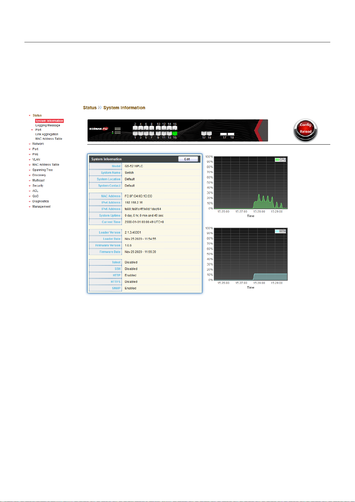
III-1-1. System Information
This page shows switch panel, CPU utilization, Memory utilization and other system
current information. It also allows user to edit some system information.
To display the Device Information web page, click Status > System Information.
8
Page 16

Item
Description
Model
Model name of the switch.
System Name
System name of the switch. This name will also use as CLI
prefix of each line. (“Switch>” or “Switch#”).
System Location
Location information of the switch.
System Contact
Contact information of the switch.
MAC Address
Base MAC address of the switch.
IPv4 Address
Current system IPv4 address.
IPv6 Address
Current system IPv6 address.
System Uptime
Total elapsed time from booting.
Current Time
Current system time.
Loader Version
Boot loader image version.
Loader Date
Boot loader image build date.
Firmware Version
Current running firmware image version.
Firmware Date
Current running firmware image build date.
Telnet
Current Telnet service enable/disable state.
SSH
Current SSH service enable/disable state.
HTTP
Current HTTP service enable/disable state.
HTTPS
Current HTTPS service enable/disable state.
SNMP
Current SNMP service enable/disable state.
Figure 12 - Status > System Information
9
Page 17

Click “Edit” button on the table title to edit following system information.
Item
Description
System Name
System name of the switch. This name will also use as CLI
prefix of each line. (“Switch>” or “Switch#”).
System Location
Location information of the switch.
System Contact
Contact information of the switch.
Item
Description
Log ID
The log identifier.
Time
The time stamp for the logging message.
Severity
The severity for the logging message.
Description
The description of logging message.
Figure 13 - Status > System Information > Edit System Information
III-1-2. Logging Message
To view the logging messages stored on the RAM and Flash, click Status > Logging
Message.
Figure 14 - Status > Logging Message
10
Page 18

Viewing
RAM: Show the logging messages stored on the RAM.
Flash: Show the logging messages stored on the Flash.
Clear
Clear the logging messages.
Refresh
Refresh the logging messages.
III-1-3. Port
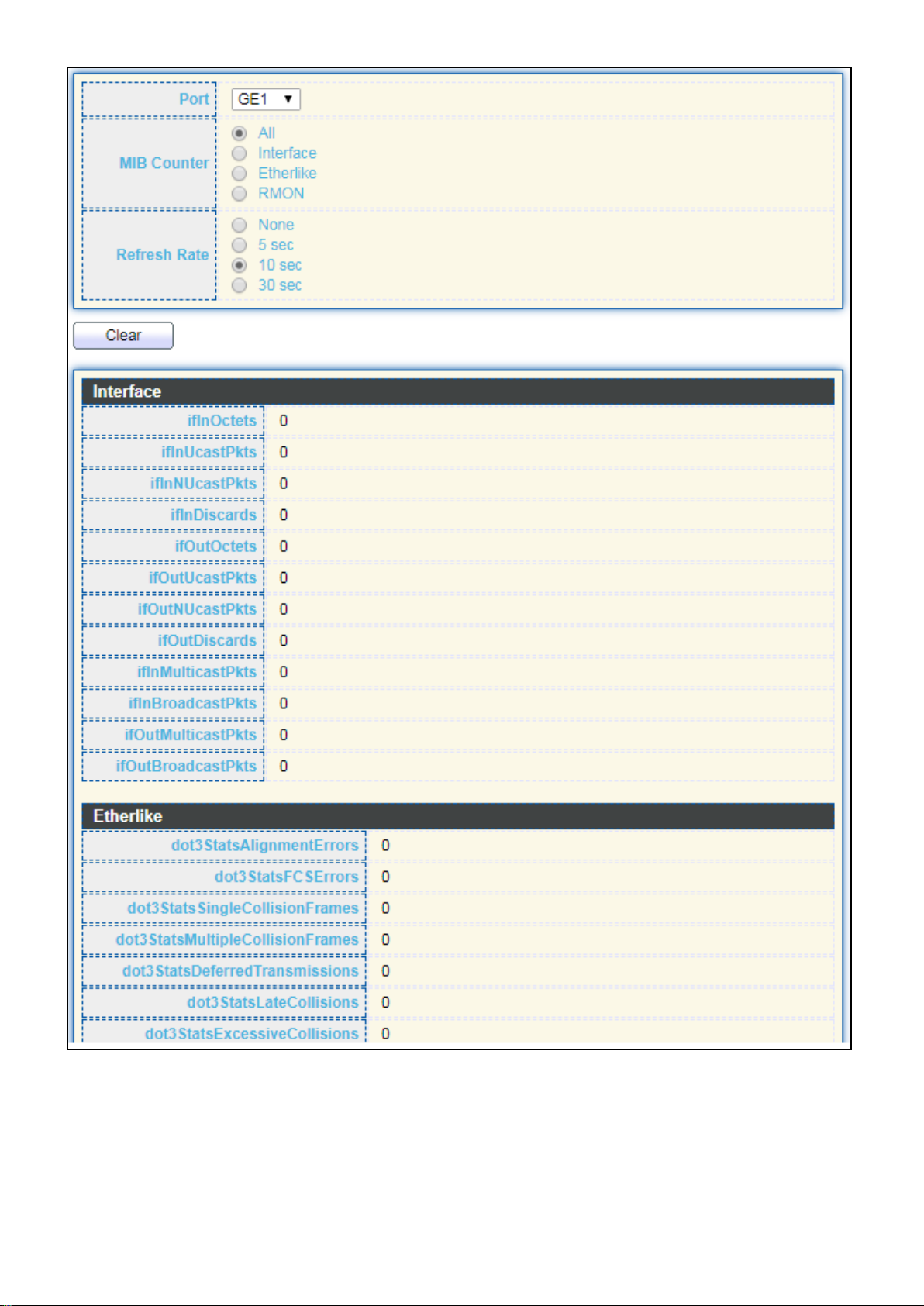
III-1-3-1. Statistics
This page displays standard counters on network traffic form the Interfaces, Ethernet
-like and RMONMIB. Interfaces and Ethernet-like counters display errors on the traffic
passing through each port. RMON counters provide a total count of different frame types
and sizes passing through each port. The “Clear” button will clear MIB counter of current
selected port.
To display the Port Flow Chart web page, click Status > Port > Statistics.
11
Page 19
12 13
Page 20

Item
Description
Port
Select one port to show counter statistics.
MIB Counter
Select the MIB counter to show different counter type
All: All counters.
Interface: Interface related MIB counters.
Etherlike: Ethernet-like related MIB counters.
RMON: RMON related MIB counters.
Refresh Rate
Refresh the web page every period of seconds to get new
counter of specified port.
Figure 15 - Status > Port > Statistics
Page 21

III-1-3-2. Error Disabled
Item
Description
□
Select one or more port to operate.
Port
Interface or port number.
Reason
Port will be disabled by one of the following error reason:
BPDU Guard
UDLD
Self Loop
Broadcast Flood
Unknown Multicast Flood
Unicast Flood
ACL
Port Security Violation
DHCP rate limit
ARP rate limit
Time Left (sec)
The time left in second for the error recovery.
Refresh
Refresh the current page.
Recover
Recover the selected port status.
To display the Error Disabled web page, click Status > Port > Error Disabled.
Figure 16 - Status > Port > Error Disabled
III-1-3-3. Bandwidth Utilization
This page allow user to browse ports’ bandwidth utilization in real time. This page will
refresh automatically in every refresh period.
14
Page 22

Item
Description
Refresh Rate
Refresh the web page every period of seconds to get new
bandwidth utilization data.
To display Bandwidth Utilization web page, click Status > Port > Bandwidth Utilization.
Figure 17 - Status > Port > Bandwidth Utilization
III-1-4. Link Aggregation
To display the Link Aggregation web page, click Status > Link Aggregation.
Figure 18 - Status > Link Aggregation
15
Page 23
Item
Description
LAG
LAG Name.
Name
LAG port description.
Type
The type of the LAG.
Static: The group of ports assigned to a static LAG are
always active members.
LACP: The group of ports assigned to dynamic LAG are
candidate ports. LACP determines which candidate ports
are active member ports.
Link Status
LAG port link status.
Active Member
Active member ports of the LAG.
Inactive Member
Inactive member ports of the LAG.
Item
Description
VLAN
VLAN ID of the mac address.
MAC Address
MAC address.
Type
The type of MAC address
Management: DUT’s base mac address for management
Purpose.
Static: Manually configured by administrator
Dynamic: Auto learned by hardware.
Port
The type of Port
CPU: DUT’s CPU port for management purpose.
Other: Normal switch port.
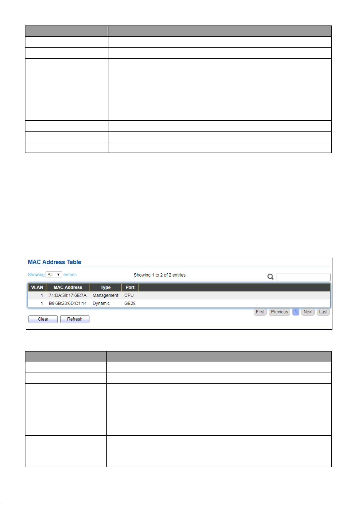
III-1-5. MAC Address Table
The MAC address table page displays all MAC address entries on the switch including
static MAC address created by administrator or auto learned from hardware. The “Clear”
button will clear all dynamic entries and “Refresh” button will retrieve latest MAC
address entries and show them on page.
To display the MAC Address Table web page, click Status > MAC Address Table.
Figure 19 - Status > MAC Address Table
16
Page 24

III-2. Network
Use the Network pages to configure settings for the switch network interface and how
the switch connects to a remote server to get services.
III-2-1. IP Address
This section allows you to edit the IP address, Netmask, Gateway and DNS server of the
switch.
To view the IP Address menu, navigate to Network > IP Address.
17
Page 25
Figure 20 - Network > IP Address
18
Page 26

Item
Description
Address Type
The address type of switch IP configuration including
Static: Static IP configured by users will be used.
Dynamic: Enable the DHCP to obtain the IP address from a
DHCP server.
IP Address
Specify the switch static IP address on the static
configuration.
Subnet Mask
Specify the switch subnet mask on the static configuration.
Default Gateway
Specify the default gateway on the static configuration. The
default gateway must be in the same subnet with switch IP
address configuration.
DNS Server 1
Specify the primary user-defined IPv4 DNS server
configuration.
DNS Server 2
Specify the secondary user-defined IPv4 DNS server
configuration.
Table 3-2: IPv6 Address fields
IPv4 Address
The operational IPv4 address of the switch.
IPv4 Gateway
The operational IPv4 gateway of the switch.
IPv6 Address v6
The operational IPv6 address of the switch.
IPv6 Gateway
The operational IPv6 gateway of the switch.
Link Local Address
The IPv6 link local address for the switch.
III-2-2. System Time
This page allow user to set time source, static time, time zone and daylight saving
settings. Time zone and daylight saving takes effect both static time or time from SNTP
server.
To display System Time page, click Network > System Time.
19
Page 27
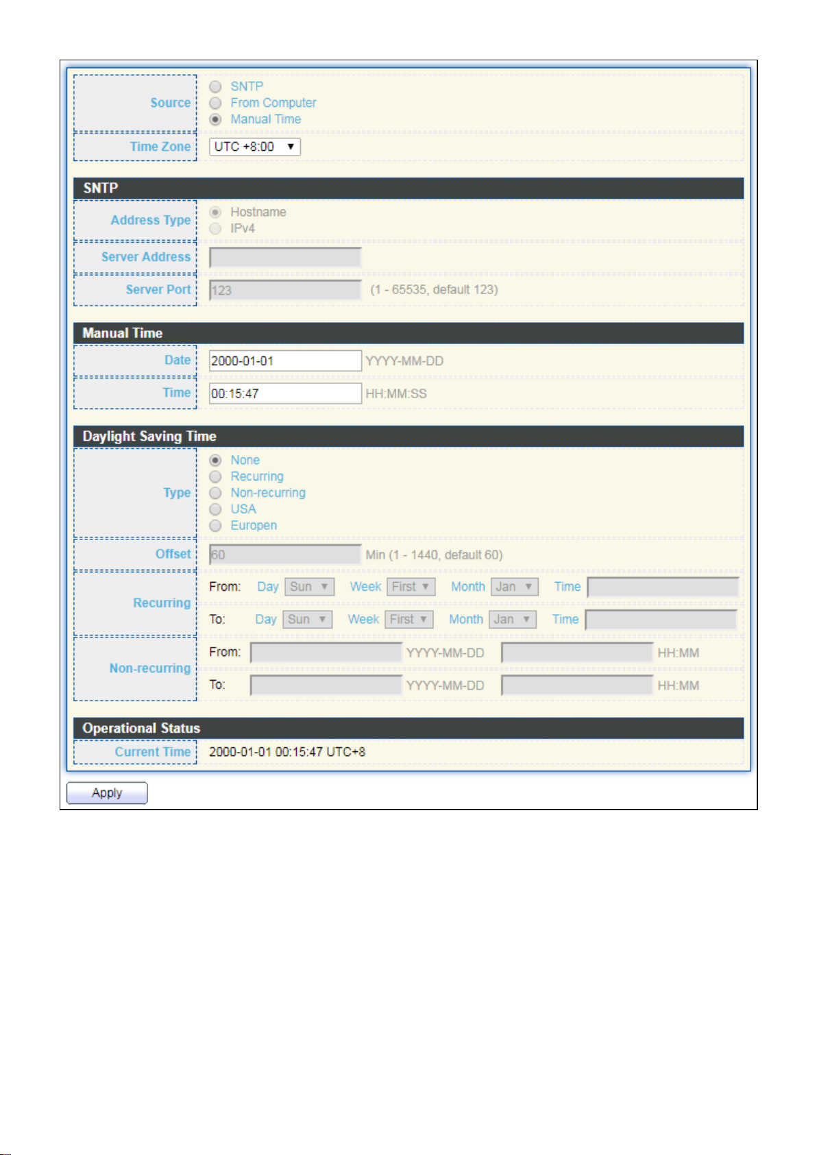
Figure 21 - Network > System Time
20
Page 28

Item
Description
Source
Select the time source.
SNTP: Time sync from NTP server.
From Computer: Time set from browser host.
Manual Time: Time set by manually configure.
Time Zone
Select a time zone difference from listing district.
SNTP
Address Type
Select the address type of NTP server. This is enabled when
time source is SNTP.
Server Address
Input IPv4 address or hostname for NTP server. This is enabled
when time source is SNTP.
Server Port
Input NTP port for NTP server. Default is 123. This is enabled
when time source is SNTP.
Manual Time
Date
Input manual date. This is enabled when time source is manual.
Time
Input manual time. This is enabled when time source is manual.
Daylight Saving Time
Type
Select the mode of daylight saving time.
Disable: Disable daylight saving time.
Recurring: Using recurring mode of daylight saving time.
Non-Recurring: Using non-recurring mode of daylight saving
time.
USA: Using daylight saving time in the United States that
starts on the second Sunday of March and ends on the first
Sunday of November.
European: Using daylight saving time in the Europe that
starts on the last Sunday in March and ending on the last
Sunday in October.
Offset
Specify the adjust offset of daylight saving time.
Recurring From
Specify the starting time of recurring daylight saving time. This
field available when selecting “Recurring” mode.
Recurring To
Specify the ending time of recurring daylight saving time. This
field available when selecting “Recurring” mode.
Non-recurring
From
Specify the starting time of non-recurring daylight saving time.
This field available when selecting “Non-Recurring” mode.
Non-recurring
To
Specify the ending time of recurring daylight saving time. This
field available when selecting “Non-Recurring” mode.
Non-recurring
From
Specify the starting time of non-recurring daylight saving time.
This field available when selecting “Non-Recurring” mode.
Non recurring
To
Specify the ending time of recurring daylight saving time. This
field available when selecting “Non-Recurring” mode.
21
Page 29
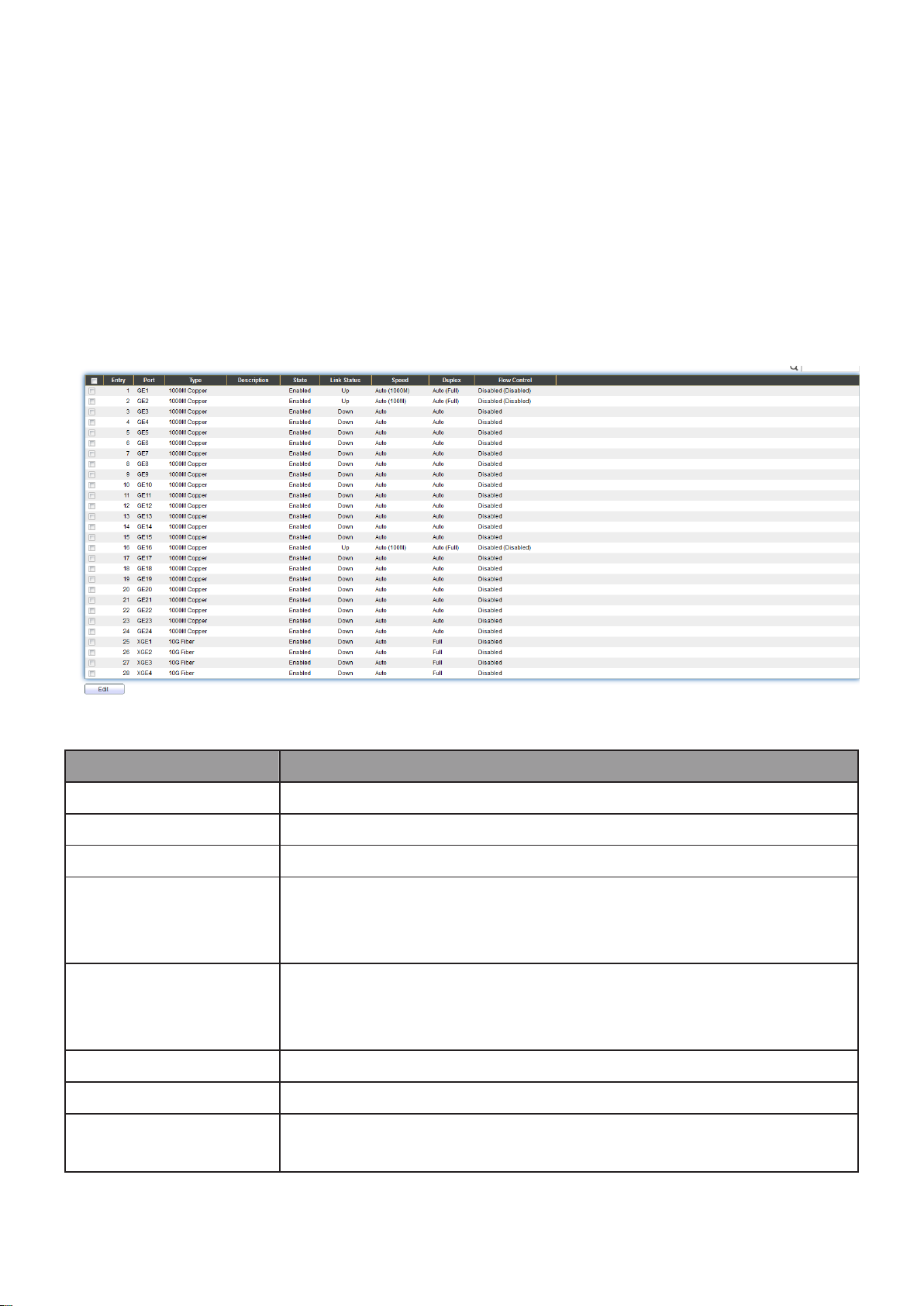
III-3. Port
Item
Description
Port
Port Name.
Type
Port media type.
Description
Port Description.
State
Port admin state
Enabled: Enable the port.
Disabled: Disable the port.
Link Status
Current port link status
Up: Port is link up.
Down: Port is link down.
Speed
Current port speed configuration and link speed status.
Duplex
Current port duplex configuration and link duplex status.
Flow Control
Current port flow control configuration and link flow control
status.
Use the Port pages to configure settings for switch port related features.
III-3-1. Port Setting
This page shows port current status and allow user to edit port configura-tions. Select
port entry and click “Edit” button to edit port configurations.
To display Port Setting web page, click Port > Port Setting.
Figure 22 - Port > Port Setting
22
Page 30
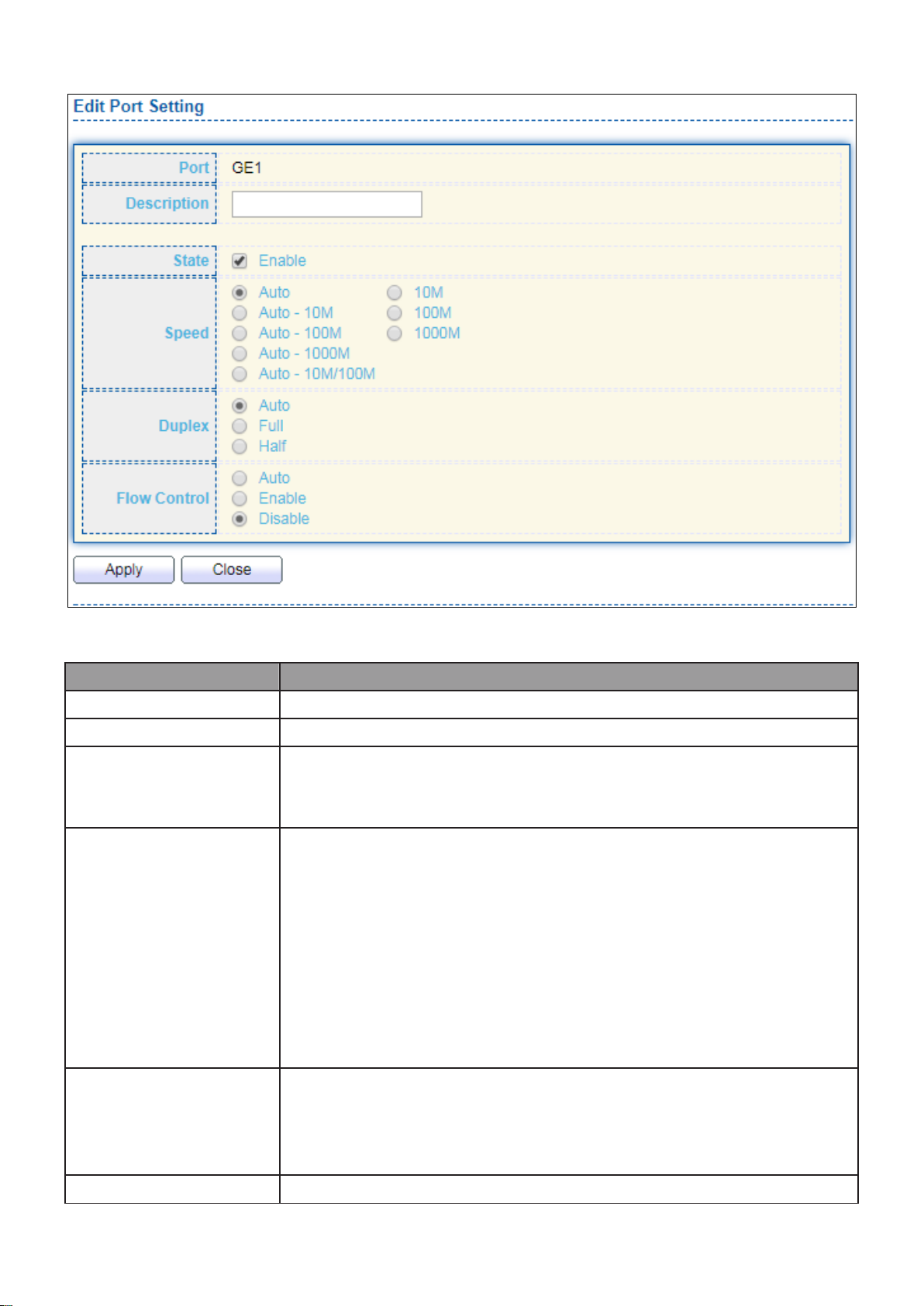
Click “Edit” button to edit Port Setting menu
Item
Description
Port
Selected Port list.
Description
Port media type.
State
Port admin state.
Enabled: Enable the port.
Disabled: Disable the port.
Speed
Port speed capabilities.
Auto: Auto speed with all capabilities.
Auto-10M: Auto speed with 10M ability only.
Auto-100M: Auto speed with 100M ability only.
Auto-1000M: Auto speed with 1000M ability only.
Auto-10M/100M: Auto speed with 10M/100M abilities.
10M: Force speed with 10M ability.
100M: Force speed with 100M ability.
1000M: Force speed with 1000M ability.
Duplex
Port duplex capabilities.
Auto: Auto duplex with all capabilities.
Half: Auto speed with 10M and 100M ability only.
Full: Auto speed with 10M/100M/1000M ability only.
Flow Control
Port flow control.
Figure 23 - Port > Port Setting > Port Setting
23
Page 31

Auto: Auto flow control by negotiation.
Enabled: Enable flow control ability.
Disabled: Disable flow control ability.
III-3-2. Long Range Mode
This page shows port current status and Enable long range mode will double the cabling
distance but reduce the speed to 10Mbps.
To display Long Range Mode web page, click Port > Long Range Mode Setting.
Figure 24 - Port > Long Range Mode
24
Page 32

III-3-3. Error Disable
Item
Description
Recover
Interval
Auto recovery after this interval for error disabled port.
BPDU Guard
Enabled to auto shutdown port when BPDU Guard reason occur.
This reason caused by STP BPDU Guard mechanism.
UDLD
Enabled to auto shutdown port when UDLD violation occur.
Self Loop
Enabled to auto shutdown port when Self Loop reason occur.
Broadcast
Flood
Enabled to auto shutdown port when Broadcast Flood reason
occur. This reason caused by broadcast rate exceed broadcast
storm control rate.
Unknown
Multicast Flood
Enabled to auto shutdown port when Unknown Multicast Flood
reason occur. This reason caused by unknown multicast rate
exceed unknown multicast storm control rate.
Unicast Flood
Enabled to auto shutdown port when Unicast Flood reason
occur. This reason caused by unicast rate exceed unicast storm
control rate.
ACL
Enabled to auto shutdown port when ACL shutdown port reason
occur. This reason caused packet match the ACL shutdown port
action.
Port Security
Enabled to auto shutdown port when Port Security Violation
To display Error Disabled web page, click Port > Error Disabled
Figure 25 - Port > Error disable
25
Page 33

reason occur. This reason caused by violation port security rules.
DHCP rate limit
Enabled to auto shutdown port when DHCP rate limit reason
occur. This reason caused by DHCP packet rate exceed DHCP rate
limit.
ARP rate limit
Enabled to auto shutdown port when ARP rate limit reason
occur. This reason caused by DHCP packet rate exceed ARP rate
limit.
Item
Description
Load Balance
Algorithm
LAG load balance distribution algorithm
src-dst-mac: Based on MAC address.
src-dst-mac-ip: Based on MAC address and IP address.
LAG
LAG Name.
Name
LAG port description.
III-3-4. Link Aggregation
III-3-4-1. Group
This page allow user to configure link aggregation group load balance algorithm and
group member.
To view the Group menu, navigate to Port > Link Aggregation > Group.
Figure 26 - Port > Link Aggregation > Group
26
Page 34

Type
The type of the LAG
Static: The group of ports assigned to a static LAG are
always active members.
LACP: The group of ports assigned to dynamic LAG are
candidate ports. LACP determines which candidate ports
are active member ports.
Link Status
LAG port link status
Active Member
Active member ports of the LAG.
Inactive Member
Inactive member ports of the LAG.
Item
Description
LAG
Selected LAG group ID.
Name
LAG port description.
Type
The type of the LAG
Static: The group of ports assigned to a static LAG are
always active members.
LACP: The group of ports assigned to dynamic LAG are
candidate ports. LACP determines which candidate ports
are active member ports.
Member
Select available port to be LAG group member port.
Click “Edit” to edit Link Aggregation Group menu.
Figure 27 - Port > Link Aggregation > Group > Edit Link Aggregation Group
27
Page 35

III-3-4-2. Port Setting
Item
Description
LAG
LAG Port Name.
Type
LAG Port media type.
Description
LAG Port description.
State
LAG Port admin state
Enabled: Enable the port.
Disabled: Disable the port.
Link Status
Current LAG port link status
Up: Port is link up.
Down: Port is link down.
Speed
Current LAG port speed configuration and link speed status.
Duplex
Current LAG port duplex configuration and link duplex
status.
Flow Control
Current LAG port flow control configuration and link flow
control status.
This page shows LAG port current status and allow user to edit LAG port configurations.
Select LAG entry and click “Edit” button to edit LAG port configurations.
To display LAG Port Setting web page, click Port > Link Aggregation > Port Setting.
Figure 28 - Port > Link Aggregation > Port Setting
28
Page 36

Click “Edit” to view Edit Port Setting menu.
Item
Description
Port
Selected Port list.
Description
Port description.
State
Port admin state
Enabled: Enable the port.
Disabled: Disable the port.
Speed
Port speed capabilities
Auto: Auto speed with all capabilities.
Auto-10M: Auto speed with 10M ability only.
Auto-100M: Auto speed with 100M ability only.
Auto-1000M: Auto speed with 1000M ability only.
Auto-10M/100M: Auto speed with 10M/100M abilities.
10M: Force speed with 10M ability.
100M: Force speed with 100M ability.
1000M: Force speed with 1000M ability.
Flow Control
Port flow control
Auto: Auto flow control by negotiation.
Enabled: Enable flow control ability.
Disabled: Disable flow control ability.
Figure 29 - Port > Link Aggregation > Port Setting > Edit Port Setting
29
Page 37

III-3-4-3. LACP
Item
Description
System Priority
Configure the system priority of LACP. This decides the
system priority field in LACP PDU.
Port
Port Name.
Port Priority
LACP priority value of the port.
Timeout
The periodic transmissions type of LACP PDUs.
Long: Transmit LACP PDU with slow periodic (30s).
Short: Transmit LACPP DU with fast periodic (1s).
This page allow user to configure LACP global and port configurations. Select ports and
click “Edit” button to edit port configuration.
To display the LACP Setting web page , click Port > Link Aggregation > LACP.
Figure 30 - Port > Link Aggregation > LACP
Click "Edit" button to view Edit LACP Port Setting menu.
Figure 31 - Port > Link Aggregation > LACP > Edit LACP Port Setting
30
Page 38

Item
Description
Port
Selected port list.
Port Priority
Enter the LACP priority value of the port
Timeout
The periodic transmissions type of LACP PDUs.
Long: Transmit LACP PDU with slow periodic (30s).
Short: Transmit LACPP DU with fast periodic (1s).
Item
Description
Port
Port Name.
State
Port EEE admin state
Enabled: EEE is enabled.
Disabled: EEE is disabled.
Operational Status
Port EEE operational status
Enabled: EEE is operating.
Disabled: EEE is no operating.
III-3-4-4. EEE
This page allow user to configure Energy Efficient Ethernet settings.
To display the EEE web page, click Port > EEE.
Click “Edit” to edit the EEE menu.
Figure 32 - Port > EEE
31
Page 39

Figure 33 - Port > EEE > Edit EEE Setting
Item
Description
Port
Port Name
State
Port EEE admin state
Enabled: EEE is enabled.
Disabled: EEE is disabled.
Item
Description
Jumbo Frame
Enable or disable jumbo frame. When jumbo frame is enabled,
switch max frame size is allowed to configure. When jumbo
frame is disabled, default frame size 1522 will be used.
III-3-5. Jumbo Frame
This page allow user to configure switch jumbo frame size.
To display Jumbo Frame web page, click Port > Jumbo Frame.
Figure 34 - Port > Jumbo Frame
III-4. PoE
Port security can set port isolation and specific behavior.
32
Page 40

III-4-1. Global Setting
To display the Global web page, click PoE > Global Setting.
Figure 35 - PoE > Global Setting
33
Page 41

Item
Description
Nominal Power
Maximum supply power.
Consuming Power
Current consumed power.
Remaining Power
Remaining available power.
Schedule Status
Schedule status global switch.
Name
PoE Schedule Name.
Port List
The ports provide power in designated schedule index.
Schedule Status
The current schedule status.
Item
Description
Index
The serial number of schedule list.
Schedule Status
Schedule Status
Checked: Schedule status is enabled.
Unchecked: Schedule status is disabled.
Name
Enter the PoE schedule name.
Date
Select a valid time for this schedule.
Port List
Select the port provide power.
Click “Edit” to view PoE Schedule List menu.
Figure 36 - PoE > Priority Setting > Edit PoE Schedule Edit
34
Page 42

III-4-2. PoE On/Off
To display the PoE Status web page, click PoE > Power On/Off.
Figure 40 - PoE > Power On/off
Per Port PoE Status
Checked: Port PoE status is enabled.
Unchecked: Port PoE status is disabled.
35
Page 43

III-4-3. PD Alive Check
This page shows the information of each ports, including mode, ping PD IP Address,
interval time, retry count, action, reboot time and connect status.
To display port setting page, please click the “Edit” button.
36
Page 44

Item
Description
Port list
Display the interface of port entry.
Status
Enable/Disable
Ping PD IP Address
Input IP address of the PD
Internal Time
The default setting about Interval (30 seconds) will
make switch detect the PD status by performing ping
requests every 30 seconds.
Retry Count
If there is no ping reply from the PD, retry count
starts to count from 1. Once retry count is reached to
2 times, the switch will perform the action in which
you defined.
Action
The Action including none, PD reboot, Reboot &
Alarm and Alarm
Reboot Time
Set the switch reboot time
III-5. VLAN
A virtual local area network, virtual LAN or VLAN, is a group of hosts with a common set
of requirements that communicate as if they were attached to the same broadcast
domain, regardless of their physical location. A VLAN has the same attributes as a
physical local area network (LAN), but it allows for end stations to be grouped togeth-er
even if they are not located on the same network switch. VLAN membership can be
configured through software instead of physically relocating devices or connections.
III-5-1. VLAN
Use the VLAN pages to configure settings of VLAN.
III-5-1-1. Create VLAN
This page allows user to add or delete VLAN ID entries and browser all VLAN entries that
add statically or dynamic learned by GVRP. Each VLAN entry has a unique name, user can
edit VLAN name in edit page.
To display Create VLAN page, click VLAN > VLAN > Create VLAN.
37
Page 45

Item
Description
Available VLAN
VLAN has not created yet.
Select available VLANs from left box then move to right box
to add.
Created VLAN
VLAN had been created.
Select created VLANs from right box then move to left box to
delete
VLAN
The VLAN ID.
Name
The VLAN Name.
Type
The VLAN Type.
Static: Port base VLAN.
Dynamic: 802.1q VLAN.
Item
Description
Name
Input VLAN name.
Figure 41 - VLAN > VLAN > Create VLAN
Click “Edit” button to view Edit VLAN Name menu.
Figure 42 - VLAN > VLAN > Create VLAN > Edit VLAN Name
38
Page 46

III-5-1-2. VLAN Configuration
Item
Description
VLAN
Select specified VLAN ID to configure VLAN configuration.
Port
Display the interface of port entry.
Mode
Display the interface VLAN mode of port.
Membership
Select the membership for this port of the specified VLAN ID.
Forbidden: Specify the port is forbidden in the VLAN.
Excluded: Specify the port is excluded in the VLAN.
Tagged: Specify the port is tagged member in the VLAN.
Untagged: Specify the port is untagged member in the
VLAN.
PVID
Display if it is PVID of interface.
This page allow user to configure the membership for each port of selected VLAN.
To display VLAN Configuration page, click VLAN > VLAN > VLAN Configuration.
Figure 43 - VLAN > VLAN > VLAN Configuration
39
Page 47

III-5-1-3. Membership
Item
Description
Port
Display the interface of port entry.
Mode
Display the interface VLAN mode of port.
Administrative
VLAN
Display the administrative VLAN list of this port.
Operational
VLAN
Display the operational VLAN list of this port. Operational VLAN
means the VLAN status that really runs in device. It may different
to administrative VLAN.
This page allow user to view membership information for each port and edit membership
for specified interface.
To display Membership page, click VLAN > VLAN > Membership.
Figure 44 - VLAN > VLAN > Membership
Click "Edit" button to view the Edit Port Setting menu
40
Page 48

Item
Description
Port
Display the interface.
Mode
Display the VLAN mode of interface.
Membership
Select VLANs of left box and select one of following membership
then move to right box to add membership. Select VLANs of right
box then move to left box to remove membership. Tagging
membership may not choose in differ VLAN port mode. Select the
time source.
Forbidden: Set VLAN as forbidden VLAN.
Excluded: This option is always disabled.
Tagged: Set VLAN as tagged VLAN.
Untagged: Set VLAN as untagged VLAN.
PVID: Check this checkbox to select the VLAN ID to be the
port-based VLAN ID for this port. PVID may auto select or can’t
select in differ settings.
Figure 45 - VLAN > VLAN > Membership > Edit Port Setting
41
Page 49

III-5-1-4. Port Setting
Item
Description
Port
Display the interface.
Mode
Display the VLAN mode of interface.
PVID
Display the Port-based VLAN ID of port.
Accept Frame Type
Display accept frame type of port.
Ingress Filtering
Display ingress filter status of port.
Uplink
Display uplink status.
TPID
Display TPID used of interface.
This page allow user to configure ports VLAN settings such as VLAN port mode, PVID
etc…The attributes depend on different VLAN port mode.
To display Port Setting page, click VLAN > VLAN > Port Setting.
Figure 46 - VLAN > VLAN > Port Setting
Click “Edit” button to Edit Port Setting menu.
42
Page 50

Item
Description
Port
Display selected port to be edited.
Mode
Select the VLAN mode of the interface.
Forbidden: Set VLAN as forbidden VLAN.
Hybrid: Support all functions as defined in IEEE 802.1Q
specification.
Access: Accepts only untagged frames and join an untagged
VLAN.
Trunk: An untagged member of one VLAN at most, and is a
tagged member of zero or more VLANs.
PVID
Specify the port-based VLAN ID (1-4094). It’s only available with
Hybrid and Trunk mode.
Accepted
Type
Specify the acceptable-frame-type of the specified interfaces. It’s
only available with Hybrid mode.
Ingress
Filtering
Set checkbox to enable/disable ingress filtering. It’s only available
with Hybrid mode.
Uplink
Set checkbox to enable/disable uplink mode. It’s only available with
trunk mode.
TPID
Select TPID used of interface. It’s only available with trunk mode.
Figure 47 - VLAN > VLAN > Port Setting > Edit Port Setting
III-5-2. Voice VLAN
Use the Voice VLAN pages to configure settings of Voice VLAN.
43
Page 51

III-5-2-1. Property
Item
Description
State
Set checkbox to enable or disable voice VLAN function.
VLAN
Select Voice VLAN ID. Voice VLAN ID cannot be default VLAN.
Cos/802.1p
Select a value of VPT. Qualified packets will use this VPT value as
inner priority.
Remarking
Set checkbox to enable or disable 1p remarking. If enabled, qualified
packets will be remark by this value.
Aging Time
Input value of aging time. Default is 1440 minutes. A voice VLAN
entry will be age out after this time if without any packet pass
through.
Port Setting Table
Port
Display port entry.
State
Display enable/disabled status of interface.
Mode
Display voice VLAN mode.
QoS Policy
Display voice VLAN remark will effect which kind of packet.
This page allow user to configure global and per interface settings of voice VLAN.
To display Property Web page, click VLAN> Voice VLAN> Property.
Figure 48 - VLAN > Voice VLAN > Property
Click “Edit” button to view Edit Port Setting menu.
44
Page 52

Item
Description
Port
Display selected port to be edited.
State
Set checkbox to enable/disabled voice VLAN function of interface.
Mode
Select port voice VLAN mode
Auto: Voice VLAN auto detect packets that match OUI table and
add received port into voice VLAN ID tagged member.
Manual: User need add interface to VLAN ID tagged member
manually.
QoS Policy
Select port QoS Policy mode
Voice Packet: QoS attributes are applied to packets with OUIs in
the source MAC address.
All: QoS attributes are applied to packets that are classified to
Voice VLAN.
Figure 49 - VLAN > Voice VLAN > Property > Edit Port Setting
III-5-2-2. Voice OUI
This page allow user to add, edit or delete OUI MAC addresses. Default has 8 pre-defined
OUI MAC.
To display the Voice OUI Web page, click VLAN > Voice VLAN > Voice OUI.
45
Page 53

Figure 50 - VLAN > Voice VLAN > Voice OUI
Item
Description
OUI
Display OUI MAC address.
Description
Display description of OUI entry.
Item
Description
OUI
Input OUI MAC address. Can’t be edited in edit dialog.
Description
Input description of the specified MAC address to the voice
VLAN OUI table.
Click “Add” or “Edit” button to Add/Edit Voice OUI menu.
Figure 51 - VLAN > Voice VLAN > Voice OUI > Add/Edit Voice OUI
46
Page 54

III-5-3. MAC VLAN
Item
Description
Group ID
Display group ID of entry.
MAC Address
Display mac address of entry.
Mask
Display mask of mac address for classified packet.
Use the MAC VLAN pages to configure settings of MAC VLAN.
III-5-3-1. MAC Group
This page allow user to add or edit groups settings of MAC VLAN.
To display the MAC page , click VLAN > MAC VLAN > MAC Group.
Figure 52 - VLAN > MAC VLAN > MAC Group
Click “Add” button or "Edit" button to view Add/Edit MAC menu.
47
Page 55

Figure 53 - VLAN > MAC VLAN > MAC Group > Add/Edit MAC
Item
Description
Group ID
Input group ID that is a unique ID of mac group entry. The
range from 1 to 2147483647. Only available on Add Dialog.
MAC Address
Input mac address for classifying packets.
Mask
Input mask of mac address.
Item
Description
Port
Display port ID that binding with MAC group entry.
Group ID
Display group ID that port binding with.
VLAN
Display VLAN ID that assign to packets which match MAC
group.
III-5-3-2. Group Binding
This page allow user to bind MAC VLAN group to each port with VLAN ID.
To display Group Binding page, click VLAN> MAC VLAN > Group Binding.
Figure 54 - VLAN > MAC VLAN > Group Binding
Click “Add” or “Edit” button to view the Add/Edit Group Binding menu.
48
Page 56

Figure 55 - VLAN > MAC VLAN > Add/Edit Group Binding
Item
Description
Port
Select ports in left box then move to right to binding with MAC group.
Or select ports in right box then move to left to unbind with MAC
group. Only interface has hybrid VLAN mode can be selected and
bound with protocol group. Only available on Add dialog.
Group ID
Select a Group ID to associate with port. Only available on Add dialog.
VLAN
Input VLAN ID that will assign to packets which match MAC group.
III-5-4. Surveillance VLAN
Use the Surveillance VLAN pages to configure settings of Surveillance VLAN.
49
Page 57

III-5-4-1. Property
Item
Description
State
Enable/Disable
VLAN
Choose none or indicate VLAN
Priority
The 802.1p standard defines seven levels of CoS from 0
through to 7 (highest priority). 802.1p is a sub-set of the
802.1q standard which added additional fields into the
header of a standard Ethernet frame allowing it to contain
VLAN identifiers as well as the priority values.
Port Aging Time
When aging is configured on an interface that's using port
security, all the dynamically learned secure addresses age
out when the aging time expire
To display Port Setting page, click the “Edit” button.
50
Page 58

Item
Description
Port
Display port entry.
State
Display enable/disabled status of interface.
Mode
Display voice VLAN mode.
QoS Policy
Display voice VLAN remark will effect which kind of packet.
Item
Description
OUI
An organizationally unique identifier (OUI) is a 24-bit number
that uniquely identifies a vendor, manufacturer, or other
organization. ... In MAC addresses, the OUI is combined with
a 24-bit number (assigned by the assignee of the OUI) to
form the address.
OUI Mask
Specifies a set of MAC addresses using a bit mask to indicate
the bits of the MAC addresses that must fit to the specified
MAC address attribute.
III-5-4-2. Surveillance OUI
To change the description of your IP camera, click the “Edit” button.
III-6. MAC Address Table
Use the MAC Address Table pages to show dynamic MAC table and configure settings for
static MAC entries.
51
Page 59

III-6-1. Dynamic Address
Item
Description
Aging Time
The time in seconds that an entry remains in the MAC
address table. Its valid range is from 10 to 630 seconds, and
the default value is 300 seconds.
Item
Description
MAC Address
The MAC address to which packets will be statically
forwarded.
VLAN
Specify the VLAN to show or clear MAC entries.
Port
Interface or port number.
To display the Dynamic Address web page, click MAC Address Table > Dynamic Address.
Figure 56 - MAC Address Table > Dynamic Address
III-6-2. Static Address
To display the Static Address web page, click MAC Address Table > Static Address.
Figure 57 - MAC Address Table > Static Address.
52
Page 60

III-6-3. Filtering Address
Item
Description
MAC Address
Specify unicast MAC address in the packets to be dropped.
VLAN
Specify the VLAN to show or clear MAC entries.
To display the Filtering Address web page, click MAC Address Table > Filtering Address.
Figure 58 - MAC Address Table > Filtering Address.
III-7. Spanning Tree
The Spanning Tree Protocol (STP) is a network protocol that ensures a loop-free topology
for any bridged Ethernet local area network.
III-7-1. Property
To display the Property web page, click Spanning Tree > Property.
53
Page 61

Figure 59 - Spanning Tree > Property
Item
Description
State
Enable/disable the STP on the switch.
Operation
Mode
Specify the STP operation mode.
STP: Enable the Spanning Tree (STP) operation.
RSTP: Enable the Rapid Spanning Tree (RSTP) operation.
MSTP: Enable the Multiple Spanning Tree (MSTP) operation.
Path Cost
Specify the path cost method.
Long: Specifies that the default port path costs are within the
range: 1-200,000,000.
Short: Specifies that the default port path costs are within the
54
Page 62

range: 1-65,535.
BPDU
Handling
Specify the BPDU forward method when the STP is disabled.
Filtering: Filter the BPDU when STP is disabled.
Flooding: Flood the BPDU when STP is disabled.
Priority
Specify the bridge priority. The valid range is from 0 to 61440, and
the value should be the multiple of 4096. It ensures the probability
that the switch is selected as the root bridge, and the lower value
has the higher priority for the switch to be selected as the root
bridge of the topology.
Hello Time
Specify the STP hello time in second to broadcast its hello message
to other bridges by Designated Ports. Its valid range is from 1 to 10
seconds.
Max Age
Specify the time interval in seconds for a switch to wait the
configuration messages, without attempting to redefine its own
configuration.
Forward
Delay
Specify the STP forward delay time, which is the amount of time
that a port remains in the Listening and Learning states before it
enters the Forwarding state. Its valid range is from 4 to 10 seconds.
TX Hold
Count
Specify the tx-hold-count used to limit the maximum numbers of
packets transmission per second. The valid range is from 1 to 10.
Region
Name
The MSTP instance name. Its maximum length is 32 characters. The
default value is the MAC address of the switch.
Revision
The MSTP revision number. Its valid rage is from 0 to 65535.
Max Hop
Specify the number of hops in an MSTP region before the BPDU is
discarded. The valid range is 1 to 40.
Operational Status
Bridge
Identifier
Bridge identifier of the switch.
Designated
Root
Identifier
Bridge identifier of the designated root bridge.
Root Port
Operational root port of the switch.
Root Path
Cost
Operational root path cost.
Topology
Change
Count
Numbers of the topology changes.
Last
Topology
Change
The last time for the topology change.
55
Page 63

III-7-2. Port Setting
Item
Description
Port
Specify the interface ID or the list of interface IDs.
State
The operational state on the specified port.
Path Cost
STP path cost on the specified port.
Priority
STP priority on the specified port.
BPDU Filter
The states of BPDU filter on the specified port.
BPDU Guard
The states of BPDU guard on the specified port.
Operational Edge
The operational edge port status on the specified port.
Operational
Point-to-Point
The operational point-to-point status on the specified port.
Port Role
The current port role on the specified port. The possible
values are: “Disabled”, “Master”, “Root”, “Designated”,
“Alternative”, and “Backup”.
Port State
The current port state on the specified port. The possible
values are: “Disabled”, “Discarding”, “Learning”, and
“Forwarding”.
Designated Bridge
The bridge ID of the designated bridge.
Designated Port
ID
The designated port ID on the switch.
Designated Cost
The path cost of the designated port on the switch.
Protocol
Migration Check
Restart the Spanning Tree Protocol (STP) migration process
(re-negotiate with its neighborhood) on the specific interface.
To configure and display the STP port settings, click STP > Port Setting.
Figure 60 - Spanning Tree > Port Setting
Click "Edit" button to view Edit Port Setting menu.
56
Page 64

Figure 61 - Spanning Tree > Port Setting > Edit Port Setting
Item
Description
Port
Selected port ID.
State
Enable/Disable the STP on the specified port.
Path Cost
Specify the STP path cost on the specified port.
Priority
Specify the STP path cost on the specified port.
Edge Port
Specify the edge mode.
Enable: Force to true state (as link to a host).
Disable: Force to false state (as link to a bridge).
In the edge mode, the interface would be put into the Forwarding
state immediately upon link up. If the edge mode is enabled for
the interface and there are BPDUs received on the interface, the
loop might be occurred in the short time before the STP state
change.
BPDU Filter
The BPDU Filter configuration avoids receiving / transmitting
BPDU from the specified ports.
Enable: Enable BPDU filter function.
57
Page 65

Disable: Disable BPDU filter function.
BPDU Guard
The BPDU Guard configuration to drop the received BPDU directly.
Enable: Enable BPDU guard function.
Disable: Disable BPDU guard function.
Point-to-Point
Specify the Point-to-Point port configuration:
Auto: The state is depended on the duplex setting of the port
Enable: Force to true state.
Disable: Force to false state
Item
Description
MSTI
Designated port number.
Priority
The bridge priority on the specified MSTI.
Bridge Identifier
The bridge identifier on the specified MSTI.
Designated Root
Bridge
The designated root bridge identifier on the specified MSTI.
Root Port
The designated root port on the specified MSTI.
Root Path Cost
The designated root path cost on the specified MSTI.
Remaining Hop
The configuration of remaining hop on the specified MSTI.
VLAN
The VLAN configuration on the specified MSTI.
III-7-3. MST Instance
To configure MST instance setting, click STP > MST Instance.
Figure 62 - Spanning Tree > MST Instance
58
Page 66

Click "Edit" button to view Edit MST Instance menu.
Item
Description
VLAN
Select the VLAN list for the specified MSTI.
Priority
Specify the bridge priority on the specified MSTI. The valid
range is from 0 to 61440, and the value must be the multiple
of 4096. It ensures the probability that the switch is selected
as the root bridge, and the lower values has the higher
priority for the switch to be selected as the root bridge of
the STP topology.
Figure 63 - Spanning Tree > MST Instance > Edit MST Instance Setting
59
Page 67

III-7-4. MST Port Setting
Item
Description
MSTI
Specify the port setting on the specified MSTI.
Port
Specify the interface ID or the list of interface IDs.
Path Cost
The port path cost on the specified MSTI.
Priority
The port priority on the specified MSTI.
Port Role
The current port role on the specified port. The possible values are:
“Disabled”, “Master”, “Root”, “Designated”, “Alternative”, and
“Backup”.
Port State
The current port state on the specified port. The possible values
are: “Disabled”, “Discarding”, “Learning”, and “Forwarding”.
Mode
The operational STP mode on the specified port.
Type
The possible value for the port type are:
Boundary: The port attaching an MST Bridge to a LAN that is
not in the same region.
Internal: The port attaching an MST Bridge to a LAN that is not
in the same region.
Designated
Bridge
The bridge ID of the designated bridge.
Designated
Port ID
The designated port ID on the switch.
Designated
Cost
The path cost of the designated port on the switch.
To configure and display MST port setting, click STP > MST Port Setting.
Figure 64 - Spanning Tree > MST Port Setting
60
Page 68

Remaining
Hop
The remaining hops count on the specified port.
Item
Description
Path Cost
Specify the STP port path cost on the specified MSTI.
Priority
Specify the STP port priority on the specified MSTI.
Click "Edit" button to view Edit MST Port Setting menu.
Figure 65 - Spanning Tree > MST Port Setting > Edit MST Port Setting
61
Page 69

III-7-5. Statistics
Item
Description
Refresh Rate
The option to refresh the statistics automatically.
Receive BPDU
(Config)
The counts of the received CONFIG BPDU.
Receive BPDU
(TCN)
The counts of the received TCN BPDU.
Receive BPDU
(MSTP)
The counts of the received MSTP BPDU.
Transmit BPDU
(Config)
The counts of the transmitted CONFIG BPDU.
Transmit BPDU
(TCN)
The counts of the transmitted TCN BPDU.
Transmit BPDU
(MSTP)
The counts of the transmitted MSTP BPDU.
Clear
Clear the statistics for the selected interfaces
View
View the statistics for the interface.
To display the STP statistics, click STP > Statistics.
Figure 66 - Spanning Tree > Statistics
Click "View" button to view the STP Port Statistic menu.
62
Page 70

Figure 67 - Spanning Tree > Statistics > STP Port Statistic
Item
Description
Refresh Rate
The option to refresh the statistics automatically.
Clear
Clear the statistics for the selected interfaces.
III-8. Discovery
Use this section to configure LLDP.
III-8-1. LLDP
LLDP is a one-way protocol; there are no request/response sequences. Informa-tion is
advertised by stations implementing the transmit function, and is received and processed
by stations implementing the receive function. The LLDP category contains LLDP and
LLDP-MED pages.
63
Page 71

III-8-1-1. Property
Item
Description
State
Enable/ Disable LLDP protocol on this switch.
LLDP Handling
Select LLDP PDU handling action to be filtered, bridging or flooded
when LLDP is globally disabled.
Filtering: Deletes the packet.
Bridging: (VLAN-aware flooding) Forwards the packet to all
VLAN members.
Flooding: Forwards the packet to all ports
TLV Advertise
Interval
Select the interval at which frames are transmitted. The default is
30 seconds, and the valid range is 5–32767 seconds.
Holdtime
Multiplier
Select the multiplier on the transmit interval to assign to TTL
(range 2–10, default = 4).
Reinitialization
Delay
Select the delay before a re-initialization (range 1–10 seconds,
default = 2).
Transmit
Delay
Select the delay after an LLDP frame is sent (range 1–8191
seconds, default = 3).
Fast Start
Repeat Count
Select fast start repeat count when port link up (range 1–10,
default = 3).
To display LLDP Property Setting web page, click Discovery > LLDP > Property.
Figure 68 - Discovery > LLDP > Property
64
Page 72

III-8-1-2. Port Setting
Item
Description
Port
Port Name.
Mode
The port LLDP mode.
Selectde TLV
The Selected LLDP TLV.
To display LLDP Port Setting, click Discovery > LLDP > Port Setting.
Figure 69 - Discovery > LLDP > Port Setting
Click "Edit" button to view Edit Port Setting menu.
65
Page 73

Figure 70 - Discovery > LLDP > Port Setting > Edit Port Setting
Item
Description
Port
Select specified port or all ports to configure LLDP state.
Mode
Select the transmission state of LLDP port interface.
Disable: Disable the transmission of LLDP PDUs.
RX Only: Receive LLDP PDUs only.
TX Only: Transmit LLDP PDUs only.
TX And RX: Transmit and receive LLDP PDUs both.
Optional
TLV
Select the LLDP optional TLVs to be carried (multiple selection is
allowed).
System Name
Port Description
System Description
System Capability
802.3 MAC-PHY
802.3 Link Aggregation
802.3 Maximum Frame Size
Management Address
802.1 PVID.
802.1 VLAN
Name
Select the VLAN Name ID to be carried (multiple selection is
allowed).
66
Page 74

III-8-1-3. Packet View
Item
Description
Port
Port Name.
In-Use (Bytes)
Total number of bytes of LLDP information in each packet.
Available
(Bytes)
Total number of available bytes left for additional LLDP
information in each packet.
Operational
Status
Overloading or not.
To display LLDP Overloading, click Discovery > LLDP > Packet View.
Figure 71 - Discovery > LLDP > Packet View
Click "Detail" button to view Packet View Detail menu.
67
Page 75

68
Page 76

Item
Description
Port
Port Name.
Mandatory TLVs
Total mandatory TLV byte size. Status is sent or
overloading.
MED Capabilities
Total MED Capabilities TLV byte size. Status is sent or
overloading.
MED Location
Total MED Location byte size. Status is sent or
overloading.
MED Network Policy
Total MED Network Policy byte size. Status is sent or
overloading.
MED Inventory
Total MED Inventory byte size. Status is sent or
overloading
MED Extended Power
via MDI
Total MED Extended Power via MDI byte size. Status is
sent or overloading.
802.3 TLVs
Total 802.3 TLVs byte size. Status is sent or overloading.
Optional TLVs
Total Optional TLV byte size. Status is sent or
overloading.
802.1 TLVs
Total 802.1 TLVs byte size. Status is sent or overloading.
Total
Total number of bytes of LLDP information in each
packet.
Figure 72 - Discovery > LLDP > Packet View > Packet View Detail
69
Page 77

III-8-1-4. Local Information
Item
Description
Chassis ID
Subtype
Type of chassis ID, such as the MAC address.
Chassis ID
Identifier of chassis. Where the chassis ID subtype is a MAC
address, the MAC address of the switch is displayed.
System Name
Name of switch.
System
Description
Description of the switch.
Capabilities
Supported
Primary functions of the device, such as Bridge, WLAN AP, or
Router.
Capabilities
Enabled
Primary enabled functions of the device.
Port ID
Subtype
Type of the port identifier that is shown.
Use the LLDP Local Information to view LLDP local device information.
To display LLDP Local Device, click Discovery > LLDP > Local Information.
Figure 73 - Discovery > LLDP > Local Information
70
Page 78

LLDP Status
LLDP Tx and Rx abilities.
LLDP Med
Status
LLDP MED enable state.
Click “Detail” button on the page to view detail information of the selected port.
71
Page 79

Figure 74 - Discovery > LLDP > Local Information > Detail
III-8-1-5. Neighbor
Use the LLDP Neighbor page to view LLDP neighbors information.
To display LLDP Remote Device, click Discovery > LLDP > Neighbor.
Figure 75 - Discovery > LLDP > Neighbor
72
Page 80

Item
Description
Local Port
Number of the local port to which the neighbor is connected.
Chassis ID Subtype
Type of chassis ID (for example, MAC address).
Port ID Subtype
Type of the port identifier that is shown.
Port ID
Identifier of port.
System Name
Published name of the switch.
Time to Live
Time interval in seconds after which the information for this
neighbor is deleted.
Click “detail” to view selected neighbor detail information
73
Page 81

74
Page 82

Figure 76 LLDP Neighbor Detail Page
75
Page 83

III-8-1-6. Statistics
Item
Description
Insertions
The number of times the complete set of information advertised
by a particular MAC Service Access Point (MSAP) has been
inserted into tables associated with the remote systems.
Deletions
The number of times the complete set of information advertised
by MSAP has been deleted from tables associated with the remote
systems.
Drops
The number of times the complete set of information advertised
by MSAP could not be entered into tables associated with the
remote systems because of insufficient resources.
Age Outs
The number of times the complete set of information advertised
The Link Layer Discovery Protocol (LLDP) Statistics page displays summary and per-port
information for LLDP frames transmitted and received on the switch.
To display LLDP Statistics status, click Discovery > LLDP > Statistics.
Figure 77 - Discovery > LLDP > Statistics
76
Page 84

by MSAP has been deleted from tables associated with the remote
systems because the information timeliness interval has expired.
Statistics Table
Port
Interface or port number.
Transmit
Frame Total
Number of LLDP frames transmitted on the corresponding port.
Receive
Frame Total
Number of LLDP frames received by this LLDP agent on the
corresponding port, while the LLDP agent is enabled.
Receive
Frame Discard
Number of LLDP frames discarded for any reason by the LLDP
agent on the corresponding port.
Receive
Frame Error
Number of invalid LLDP frames received by the LLDP agent on the
corresponding port, while the LLDP agent is enabled.
Receive TLV
Discard
Number of TLVs of LLDP frames discarded for any reason by the
LLDP agent on the corresponding port.
Receive TLV
Unrecognized
Number of TLVs of LLDP frames that are unrecognied while the
LLDP agent is enabled.
Neighbor
Timeout
Number of age out LLDP frames.
III-9. Multicast
Use this section to configure Multicast.
III-9-1. General
Use the General pages to configure settings of IGMP and MLD common function.
III-9-1-1. Property
To display multicast general property Setting web page, click Multicast> General>
Property.
77
Page 85

Item
Description
Unknown
Multicast
Action
Set the unknown multicast action
Flood: flood the unknown multicast data.
Drop: drop the unknown multicast data.
Router port: forward the unknown multicast data to router
port.
IPv4
Set the ipv4 multicast forward method.
MAC-VID: forward method dmac+vid.
DIP-VID: forward method dip+vid.
IPv6
MAC-
DIP-VID: forward method dip+vid(dip is ipv6 low 32 bit).
Figure 78 - Multicast > General > Property
III-9-1-2. Group Address
This page allow user to browse all multicast groups that dynamic learned or statically
added.
To display Multicast General Group web page, click Multicast> General > Group Address.
Figure 79 - Multicast > General > Group Address
78
Page 86

Item
Description
IP Version
IP Version
IPv4: ipv4 multicast group
IPv6: ipv6 multicast group
VLAN
The VLAN ID of group.
Group Address
The group IP address.
Member
The member ports of group.
Type
The type of group. Static or Dynamic.
Life(Sec)
The life time of this dynamic group.
Click “Add” or “Edit” button to view Add or Edit Group Address menu.
Figure 80 - Multicast > General > Group Address > Add/Edit Group Address
79
Page 87

Item
Description
VLAN
The VLAN ID of group.
IP Version
IP Version
IPv4: ipv4 multicast group
IPv6: ipv6 multicast group
Group
Address
The group IP address.
Member
The member ports of group.
Available Port: Optional port member
Selected Port: Selected port member
Item
Description
IP Version
IP Version
IPv4: ipv4 multicast router
IPv6: ipv6 multicast router
VLAN
The VLAN ID router entry.
Member
Router Port member (include static and learned port
Static Port
Static router port member.
Forbidden Port
Forbidden router port member.
Life (Sec)
The expiry time of the router entry.
III-9-1-3. Router Port
This page allow user to browse all router port information. The static and forbidden
router port can set by user.
To display multicast router port table web page, click Multicast > General > Router Port.
Figure 81 - Multicast > General > Router Port
Click "Add" or “Edit” button to view Add/Edit Router Port menu.
80
Page 88

Figure 82 - Multicast > General > Router Port > Add/Edit Router Port
81
Page 89

Item
Description
VLAN
The VLAN ID for router entry
Available VLAN: Optional VLAN member
Selected VLAN: Selected VLAN member.
IP Version
IP Version
IPv4: ipv4 multicast router
IPv6: ipv6 multicast router
Type
The router port type
Static: static router port
Forbidden: forbidden router port, can’t learn dynamic
router port member
Port
The member ports of router entry.
Available Port: Optional router port member
Selected Port: Selected router port member
III-9-2. IGMP Snooping
Use the IGMP Snooping pages to configure settings of IGMP snooping function.
III-9-2-1. Property
This page allow user to configure global settings of IGMP snooping and configure specific
VLAN settings of IGMP Snooping.
To display IGMP Snooping global setting and VLAN Setting web page, click Multicast >
IGMP Snooping > Property.
Figure 83 - Multicast > IGMP Snooping > Property
82
Page 90

Item
Description
State
Set the enabling status of IGMP Snooping functionality
Enable: If Checked Enable IGMP Snooping, else is Disabled
IGMP Snooping.
Version
Set the igmp snooping version
IGMPv2: Only support process igmp v2 packet.
IGMPv3: Support v3 basic and v2.
Report Suppression
Set the enabling status of IGMP v2 report suppression
Enable: If Checked Enable IGMP Snooping v2 report
suppression, else Disable the report suppression function.
VLAN
The IGMP entry VLAN ID.
Operation Status
The enable status of IGMP snooping VLAN functionality.
Router Port Auto
Learn
The enabling status of IGMP snooping router port auto
learning.
Query Robustness
The Query Robustness allows tuning for the expected packet
loss on a subnet.
Query Interval
The interval of querier to send general query.
Query Max
Response
Interval
In Membership Query Messages, it specifies the maximum
allowed time before sending a responding report in units of
1/10 second.
Last Member
Query count
The count that Querier-switch sends Group-Specific Queries
when it receives a Leave Group message for a group.
Last Member
Query Interval
The interval that Querier-switch sends Group-Specific
Queries when it receives a Leave Group message for a group.
Immediate leave
The immediate leave status of the group will immediate
leave when receive IGMP Leave message.
83
Page 91

Click "Edit" button to Edit VLAN Setting menu.
Item
Description
VLAN
The selected VLAN List.
State
Set the enabling status of IGMP Snooping VLAN functionality
Enable: If Checked Enable IGMP Snooping VLAN, else is Disabled
IGMP Snooping VLAN.
Router Port
Auto Learn
Set the enabling status of IGMP Snooping router port learning
Enable: If checked Enable learning router port by query and PIM,
DVRMP, else Disable the learning router port.
Immediate
leave
Immediate Leave the group when receive IGMP Leave message.
Enable: If checked Enable immediate leave, else disable
immediate leave.
Query
The Admin Query Robustness allows tuning for the expected
Figure 84 - Multicast > IGMP Snooping > Property >Edit VLAN Setting
84
Page 92

Robustness
packet loss on a subnet.
Query Interval
The Admin interval of querier to send general query.
Query Max
Response
Interval
The Admin query max response interval, In Membership Query
Messages, it specifies the maximum allowed time before sending
a responding report in units of 1/10 second.
Last Member
Query Counter
The Admin last member query count that Querier-switch sends
Group-Specific Queries when it receives a Leave Group message
for a group.
Last Member
Query
Interval
The Admin last member query interval that Querier-switch
sends Group-Specific Queries when it receives a Leave Group
message for a group.
Operational Status
Status
Operational IGMP snooping status, must both IGMP snooping
global and IGMP snooping enable the status will be enable.
Query
Robustness
Operational Query Robustness.
Query Interval
Operational Query Interval.
Query Max
Response
Interval
Operational Query Max Response Interval
Last Member
Query
Counter
Operational Last Member Query Count.
Last Member
Query
Interval
Operational Last Member Query Interval.
III-9-2-2. Querier
This page allow user to configure querier settings on specific VLAN of IGMP Snooping.
To display IGMP Snooping Querier Setting web page, click Multicast > IGMP Snooping >
Querier.
85
Page 93

Figure 85 - Multicast > IGMP Snooping > Querier
Item
Description
VLAN
IGMP Snooping querier entry VLAN ID.
State
The IGMP Snooping querier Admin State.
Operational Status
The IGMP Snooping querier operational status.
Querier Version
The IGMP Snooping querier operational version.
Querier IP
The operational Querier IP address on the VLAN.
Item
Description
VLAN
The Selected Edit IGMP Snooping querier VLAN List.
State
Set the enabling status of IGMP Querier Election on the
chose VLANs
Enabled: if checked Enable IGMP Querier else Disable IGMP
Querier.
Version
Set the query version of IGMP Querier Election on the chose
VLANs
IGMPv2: Querier version 2.
IGMPv3: Querier version 3. (IGMP Snooping version
should be IGMPv3)
Click "Edit" button to view Edit Querier menu.
Figure 86 - Multicast > IGMP Snooping > Querier > Edit Querier
86
Page 94

III-9-2-3. Statistics
Item
Description
Receive Packet
Total
Total RX igmp packet, include ipv4 multicast data to CPU.
Valid
The valid igmp snooping process packet.
InValid
The invalid igmp snooping process packet.
Other
The ICMP protocol is not 2, and is not ipv4 multicast data packet.
Leave
IGMP leave packet.
Report
IGMP join and report packet.
General Query
IGMP General Query packet.
Special Group
Query
IGMP Special Group General Query packet.
This page allow user to clear igmp snooping statics.
To display IGMP Snooping Statistics, click Multicast > IGMP Snooping > Statistics.
Figure 87 - Multicast > IGMP Snooping > Statistics
87
Page 95

Source-specific
Group Query
IGMP Special Source and Group General Query packet.
Transmit Packet
Leave
IGMP leave packet
Report
IGMP join and report packet
General Query
IGMP general query packet include querier transmit general
query packet.
Special Group
Query
IGMP special group query packet include querier transmit special
group query packet.
Source-specific
Group Query
IGMP Special Source and Group General Query packet.
III-9-3. MVR
Use the MVR pages to configure settings of MVR function.
III-9-3-1. Property
To display multicast MVR property Setting web page, click Multicast > MVR > Property.
Figure 88 - Multicast > MVR > Property
88
Page 96

Item
Description
State
Enable: if checked enable the MVR state, else disable the MVR state.
VLAN
The MVR VLAN ID.
Mode
Set the MVR mode
Compatible: compatible mode.
Dynamic: learn group member on source port.
Group Start
MVR group range start.
Group
Count
MVR group continue count.
Query Time
MVR query time when receive MVR leave MVR group packet.
Maximum
The max number of MVR group database.
Current
The learned MVR group current time
Item
Description
Entry
Entry of number.
Port
Port Name.
Role
Port Role for MVR, the type is None/Receiver/Source.
Immediate Leave
Status of immediate leave.
III-9-3-2. Port Setting
This page allow user to configure port role and port immediate leave.
To display MVR port role and immediate leave state setting web page, click Multicast >
MVR > Port Setting.
Figure 89 - Multicast > MVR > Port Setting
89
Page 97

Click "Edit" button to view Edit Port Setting menu.
Item
Description
Port
Display the selected port list.
Role
MVR port role
None: port role is none.
Receiver: port role is receiver.
Source: port role is source.
Immediate Leave
MVR Port immediate leave
Enable: if checked is enable immediate leave, else disable
immediate leave.
Figure 90 - Multicast > MVR > Port Setting > Edit Port Setting
III-9-3-3. Group Address
This page allow user to browse all multicast MVR groups that dynamic learned or
statically added.
To display Multicast MVR Group web page, click Multicast > MVR > Group Address.
Figure 91 - Multicast > MVR > Group Address
90
Page 98

Item
Description
VLAN
The VLAN ID of MVR group.
Group
Address
The MVR group IP address.
Member
The member ports of MVR group.
Type
The type of MVR group. Static or Dynamic.
Life(Sec)
The life time of this dynamic MVR group.
Item
Description
VLAN
The VLAN ID of MVR group.
Group
Address
The MVR group IP address.
Member
The member ports of MVR group.
Available Port: Optional port member, it is only receiver port
when MVR mode is compatible, it include source port when
mode is dynamic.
Selected Port: Selected port member
Click "Add" button to view Add/Edit Group Address Table menu.
Figure 92 - Multicast > MVR > Group Address > Add Group Address
91
Page 99

III-10. Security
Item
Description
Retry
Set default retry number.
Timeout
Set default timeout value.
Key String
Set default RADIUS key string
RADIUS Table
Server
Address
RADIUS server address.
Server Port
RADIUS server port.
Priority
RADIUS server priority (smaller value has higher priority). RADIUS
session will try to establish with the server setting which has highest
priority. If failed, it will try to connect to the server with next higher
priority.
Retry
RADIUS server retry value. If it is fail to connect to server, it will keep
Use the Security pages to configure settings for the switch security features.
III-10-1. RADIUS
This page allow user to add, edit or delete RADIUS server settings and modify default
parameter of RADIUS server.
To display RADIUS web page, click Security > RADIUS.
Figure 93 - Security > RADIUS
92
Page 100

trying until timeout with retry times.
Timeout
RADIUS server timeout value. If it is fail to connect to server, it will
keep trying until timeout.
Usage
RADIUS server usage type
Login: For login authentifation.
802.1x: For 802.1x authentication.
All: For all types.
Click "Add" or “Edit” button to view Add/Edit RADIUS Server menu.
93
 Loading...