

Page 1

AR-7211A/B V2
Quick Installation Guide
10-2012 / v1.0
Page 2

1
COPYRIGHT
Copyright Edimax Technology Co., Ltd. all rights reserved. No part of
this publication may be reproduced, transmitted, transcribed, stored in a
retrieval system, or translated into any language or computer language, in
any form or by any means, electronic, mechanical, magnetic, optical,
chemical, manual or otherwise, without the prior written permission from
Edimax Technology Co., Ltd.
Edimax Technology Co., Ltd. makes no representations or warranties,
either expressed or implied, with respect to the contents hereof and
specifically disclaims any warranties, merchantability, or fitness for any
particular purpose. Any software described in this manual is sold or licensed
as is. Should the programs prove defective following their purchase, the
buyer (and not this company, its distributor, or its dealer) assumes the entire
cost of all necessary servicing, repair, and any incidental or consequential
damages resulting from any defect in the software. Edimax Technology Co.,
Ltd. reserves the right to revise this publication and to make changes from
time to time in the contents hereof without the obligation to notify any
person of such revision or changes.
The product you have purchased and the setup screen may appear
slightly different from those shown in this QIG. For more information about
this product, please refer to the user manual on the CD-ROM. The software
and specifications are subject to change without notice. Please visit our
website www.edimax.com for updates. All brand and product names
mentioned in this manual are trademarks and/or registered trademarks of
their respective holders.
Edimax Technology Co., Ltd.
Add: No. 3, Wu-Chuan 3rd Rd., Wu-Ku Industrial Park, New Taipei City, Taiwan
Tel: +886-2-77396888
Email: sales@edimax.com.tw
Page 3
2
PRODUCT INTRODUCTION
Package Contents
Before you start using this product, please check if there is anything
missing in the package and contact your dealer to claim the missing
item(s):
ADSL2+ router (AR-7211A V2 or AR-7211B V2)
Power adapter
1 meter RJ-45 Ethernet cable
1.8M RJ-11 telephone line x 2
Quick installation guide
CD containing setup wizard, user manual & multi-language QIG
System Requirements
Recommended system requirements are as follows.
A 10/100 base-T Ethernet card installed in your PC
A hub or Switch (connected to several PCs through one of the Ethernet
interfaces on the device)
Operating system: Windows 98 SE, Windows 2000, Windows ME,
Windows XP or higher
Internet Explorer V5.0 or higher, Netscape V4.0 or higher, or Firefox
1.5 or higher
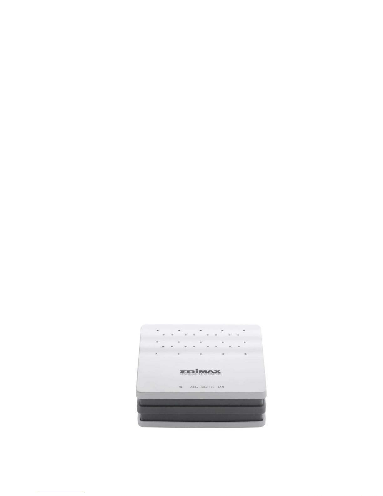
LED & Button Definitions
Front Panel
Figure 1
Page 4

3
LEDs
Color
Status
Description
Green
ON
Powered on
OFF
Powered off
Red
ON
ADSL broadband initial self-test failed or upgrading
firmware
ADSL
Green
ON
ADSL line is synchronized and ready to use
SLOW
BLINK
ADSL synchronization failed ( Please refer to Note
1)
FAST BLINK
ADSL negotiation is in progress.
Internet
Green
ON
Internet connected in router mode
BLINK
Internet activity (transferring/receiving data) in
router mode
OFF
Device in bridged mode
Red
ON
Internet not connected in router mode
(Please refer to Note 2)
LAN
Green
ON
LAN port connected
BLINK
LAN activity (transferring/receiving data)
OFF
LAN port not connected
Note:
1) If the ADSL LED is off, please check your Internet connection. Refer to A .
Hardware Installation for more information about how to connect the
router correctly. If all connections are correct, please contact your ISP to
check if there is a problem with your Internet service.
2) If the Internet LED is red, please check your ADSL LED first. If your ADSL
LED is off, refer to Note 1. If the green ADSL LED is ON, please check your
Internet configuration. You may need to check with your ISP that your
Internet is configured correctly.
Rear Panel
Figure 2
Page 5

4
Items
Description
Power ON/OFF
5V
Power connector
LAN
Ethernet RJ-45 port
Reset
Resets device to factory defaults
(to reset to factory defaults, push a paper clip into the hole when the device is
powered and hold for more than 10 seconds)
Line
Line RJ-11 port
GETTING STARTED
A. Hardware Installation
Step 1: Connect the ADSL line
Connect the Line interface of the device to the Modem interface of a
splitter using a telephone cable. Connect a telephone to the Phone
interface of the splitter using a telephone cable. Connect the Line interface
of the splitter to your existing, incoming line.
The splitter has three interfaces:
Line: Connect to a wall phone jack (RJ-11 jack).
Modem: Connect to the ADSL jack of the device.
Phone: Connect to a telephone set.
Step 2: Connect the router to your LAN network
Connect the LAN interface of the router to your PC, Hub or Switch using an
Ethernet cable (MDI/MDIX).
Note:
Use twisted-pair Ethernet cables to connect the router to a hub or
switch.
Step 3: Connect the power adapter to the router
Plug one end of the power adapter into a wall outlet and connect the other
end to the 5V interface of the device.
The following diagram shows how to correctly connect the router, PC,
splitter and the telephone sets.
Page 6

5
Step 4: Check the ADSL LED status
Please check the ADSL LED on the front panel. This light indicates the status
of your ADSL broadband through your telephone line. If the light is on, you
can continue setup. However if the light is flashing, there is no broadband
line detected. Please call your Internet Service Provider (ISP) and inform
them about the flashing ADSL light to resolve the issue.
Step 5: Firewall settings
Please turn off all personal firewalls before you continue the setup – firewalls
can block communication between your PC and router.
Note: You must use the power adapter included in the package with the
router, do NOT attempt to use a third-party power adapter.
Step 6: PC LAN IP configuration
Configure your PC’s LAN settings to automatically obtain an IP address from
the router by following the steps below:
1. Click “Start” and then select “Control Panel”.
Page 7

6
2. Click “Switch to Classic View” in the top left to show additional setting
icons.
3. Locate the “Network Connections” icon and double-click to open
network connection settings.
4. Select the “Local Area Connection” icon and right-click it to open the
sub-menu, then select “Properties”.
5. Select “Internet Protocol (TCP/IP)” and then click “Properties”
Page 8

7
6. Ensure that “Obtain an IP address automatically” and “Obtain DNS
server address automatically” are selected and then press “OK”.
B. Internet Connection
You can configure the router by running the setup wizard on the CD-ROM
included in the package contents. The wizard enables you to configure
your Internet connection, upgrade the firmware and change the router’s
password. When you start the setup wizard, you will see the following
screen. Please choose a language and follow the on screen instructions
until setup is complete.
Page 9

8
Alternatively, if you lose the CD-ROM or prefer a web based setup, you can
login to the ADSL router using Internet Explorer, and configure the router
from there using the web-based interface. Please follow the instructions
below:
.
1. Enter the router’s default IP address: “192.168.2.1” into your PC’s web
browser and press “Enter”.
2. The login screen below will appear. Enter the default username “admin”
and default password “1234” and click “OK”.
Page 10

9
3. You will arrive at the system status page as shown below.
4. In the navigation bar across the top of the screen, click “Wizard”. The
Wizard page of the web-based interface allows fast configuration of the
Internet connection and other parameters. Please refer to the user manual
for detailed information on these parameters. Enter the required
information on each page of the wizard and click “Next” until the wizard is
complete.
NNoottee:: PPlleeaassee rreeffeerr ttoo tthhee UUsseerr MMaannuuaall oonn tthhee iinncclluuddeedd CCDD--RROOMM ffoorr mmoorree
ddeettaaiilleedd iinnffoorrmmaattiioonn rreeggaarrddiinngg ccoonnffiigguurraattiioonn aanndd IInntteerrnneett ccoonnnneeccttiioonn
ttyyppee..
Page 11

10
Declaration of Conformity
We, Edimax Technology Co., LTD., declare under our sole responsibility, that the equipment
described below complies with the requirements of the European Council directive
(2004/108/EC, 92/31/EEC, 2006/95/EC).
Equipment
:
Fast Ethernet ADSL2/2+ Modem Router
Model No.
:
AR-7211A V2 / AR-7211B V2
The following European standards for essential requirements have been followed:
EMI:EN 55022:2010
EN 61000-3-2:2006+A1:2009+A2:2009
EN 61000-3-3:2008
EMS:EN 55024:2010
EN 61000-4-2:2009
EN 61000-4-3:2006+A1:2008+A2:2010
EN 61000-4-4:2004+A1:2010
EN 61000-4-5:2006
EN 61000-4-6:2009
EN 61000-4-11:2004
LVD: EN-60950-1:2006
Edimax Technology Co., Ltd.
No. 3, Wu Chuan 3rd Road,
Wu-Ku Industrial Park.
New Taipei City, Taiwan
Date of Signature:
October, 2012
Signature:
Printed Name:
Albert Chang
Title:
Director
Edimax Technology Co., Ltd.
Page 12

11
 Loading...