

Page 1

APC500
User Manual
11-2015 / v1.0
Page 2

CONTENTS
I. Product Information .............................................................................. 1
I-1. Package Contents .................................................................................................................. 2
I-2. System Requirements ............................................................................................................ 3
I-3. Hardware Overview ............................................................................................................... 3
I-4. LED Status .............................................................................................................................. 4
I-5. Reset ...................................................................................................................................... 4
I-6. Console/HyperTerminal ......................................................................................................... 5
I-7. Safety Information ................................................................................................................. 6
II. Hardware Installation ............................................................................ 7
II-1. Wall Mount ............................................................................................................................ 7
II-2. Rack Mount ............................................................................................................................ 8
III. Quick Setup ........................................................................................... 9
IV. Software Layout ................................................................................... 16
V. Features ............................................................................................... 23
V-1. LOGIN, LOGOUT & RESTART ................................................................................................ 23
V-2. DASHBOARD ........................................................................................................................ 25
V-2-1. System Information ............................................................................................................. 26
V-2-2. Devices Information ............................................................................................................. 26
V-2-3. Managed AP ......................................................................................................................... 27
V-2-4. Managed AP Group .............................................................................................................. 28
V-2-5. Active Clients ....................................................................................................................... 29
V-2-6. Active Users ......................................................................................................................... 30
V-3. ZONE PLAN ........................................................................................................................... 31
V-4. NMS MONITOR .................................................................................................................... 33
V-4-1. Access Point ......................................................................................................................... 33
V-4-1-1. Managed AP ................................................................................................................. 33
V-4-1-2. Managed AP Group ...................................................................................................... 35
V-4-2. WLAN ................................................................................................................................... 37
V-4-2-1. Active WLAN ................................................................................................................ 37
V-4-2-2. Active WLAN Group ..................................................................................................... 38
V-4-3. Clients .................................................................................................................................. 38
V-4-3-1. Active Clients ............................................................................................................... 38
V-4-4. Users .................................................................................................................................... 39
V-4-4-1. Active Users ................................................................................................................. 39
Page 3

V-4-4-2. Users Log ...................................................................................................................... 39
V-4-5. Rogue Devices ...................................................................................................................... 40
V-4-6. Information .......................................................................................................................... 41
V-4-6-1. All Events/Activities ..................................................................................................... 41
V-4-6-2. Monitoring ................................................................................................................... 42
V-5. NMS Settings ........................................................................................................................ 43
V-5-1. Access Point ......................................................................................................................... 43
V-5-2. WLAN ................................................................................................................................... 56
V-5-2-1. No Authentication ..................................................................................................... 58
V-5-2-2. WEP ............................................................................................................................ 58
V-5-2-3. IEEE802.1x/EAP .......................................................................................................... 59
V-5-2-4. WPA-PSK .................................................................................................................... 59
V-5-2-5. WPA-EAP .................................................................................................................... 60
V-5-2-6. Additional Authentication ......................................................................................... 60
V-5-3. RADIUS ................................................................................................................................. 62
V-5-4. Access Control ..................................................................................................................... 68
V-5-5. Guest Network ..................................................................................................................... 71
V-5-6. Users .................................................................................................................................... 75
V-5-7. Guest Portal ......................................................................................................................... 78
V-5-7-1. Add/Edit Guest Portal ............................................................................................................ 79
V-5-7-1-1. Front Desk URL ................................................................................................................... 80
V-5-7-1-2. Front Desk Printout ............................................................................................................ 82
V-5-7-1-3. Guest Portal Type ............................................................................................................... 83
V-5-7-1-4. Guest Portal Customization ................................................................................................ 84
V-5-8. Zone Edit .............................................................................................................................. 85
V-5-9. Schedule ............................................................................................................................... 87
V-5-10. Device Monitoring ............................................................................................................. 89
V-5-11. Firmware Upgrade ....................................................................................................... 90
V-5-12. Advanced ........................................................................................................................... 91
V-5-12-1. System Security ............................................................................................................ 91
V-5-12-2. Date & Time ................................................................................................................. 91
V-6. Local Network ...................................................................................................................... 93
V-6-1. Network Settings ................................................................................................................. 93
V-6-1-1. LAN-Side IP Address ..................................................................................................... 93
V-6-1-2. LAN Port Settings ......................................................................................................... 96
V-6-1-3. VLAN ............................................................................................................................ 97
V-7. Local Settings ....................................................................................................................... 98
V-7-1. System Settings .................................................................................................................... 98
V-7-1-1. System Information ..................................................................................................... 98
V-7-1-2. Log ..............................................................................................................................100
V-7-2. Management .....................................................................................................................101
Page 4

V-7-2-1. Admin .......................................................................................................................101
V-7-2-2. Date and Time ..........................................................................................................103
V-7-2-3. Syslog Server ............................................................................................................105
V-7-2-4. I’m Here ...................................................................................................................106
V-7-3. Advanced ...........................................................................................................................107
V-7-3-1. LED Settings ...............................................................................................................107
V-7-3-2. Update Firmware .....................................................................................................107
V-7-3-3. Save/Restore Settings ..............................................................................................109
V-7-3-4. Factory Default ........................................................................................................110
V-7-3-5. Reboot .....................................................................................................................110
V-8. Toolbox ..............................................................................................................................111
V-8-1. Network Connectivity ......................................................................................................111
V-8-1-1. Ping ..........................................................................................................................111
V-8-1-2. Trace Route ..............................................................................................................111
VI. Appendix ........................................................................................... 112
VI-1. Configuring your IP address .............................................................................................112
VI-1-1. Windows XP .....................................................................................................................113
VI-1-2. Windows Vista .................................................................................................................115
VI-1-3. Windows 7 .......................................................................................................................117
VI-1-4. Windows 8 .......................................................................................................................121
VI-1-5. Mac ..................................................................................................................................125
VII. Best Practice ...................................................................................... 127
VII-1. How to Create and Link WLAN & Access Point Groups ...................................................127
Federal Communication Commission Interference Statement .. 錯誤! 尚未定
義書籤。
Page 5

Page 6

L2/L3 AP Management
Captive Portal/Guest Policy
QoS by SSID
Local Radius (AAA)
Batch Setup/Configuration
Group Firmware Upgrade/Restart
Channel/RF Power/Load Optimization
Edimax NMS
Edimax Pro NMS
CAP Series
WAP Series
APC500
Platform
Software
Software
Standalone Box
Segment
Entry
Middle
High
Managed AP Capacity
1 – 8
1 – 16
1 - 32
I. Product Information
The APC500 supports central management for up to 32 Edimax Pro access
points, suitable for SMBs/SMEs. Functions include:
Edimax Pro Network Management Suite (NMS) supports the central
management of a group of access points, otherwise known as an AP Array.
NMS can be installed on one access point and support up to 16 Edimax Pro
access points with no additional wireless controller required. The APC500 is a
standalone AP Controller with support for up 32 APs.
The APC500 Controller connects to a network via a switch or directly to a
router, and other connected Edimax Pro access points are automatically
designated as Managed APs. Using the APC500 you can configure, monitor
and manage all Managed APs (up to 32 connected by switches) from the
single AP Controller.
Access points can be deployed and configured according to requirements,
creating a powerful network architecture which can be easily managed and
expanded in the future, with an easy to use interface and a full range of
functionality – ideal for small and mid-sized office environments. A secure
WLAN can be deployed and administered from a single point, minimizing cost
and complexity.
1
Page 7
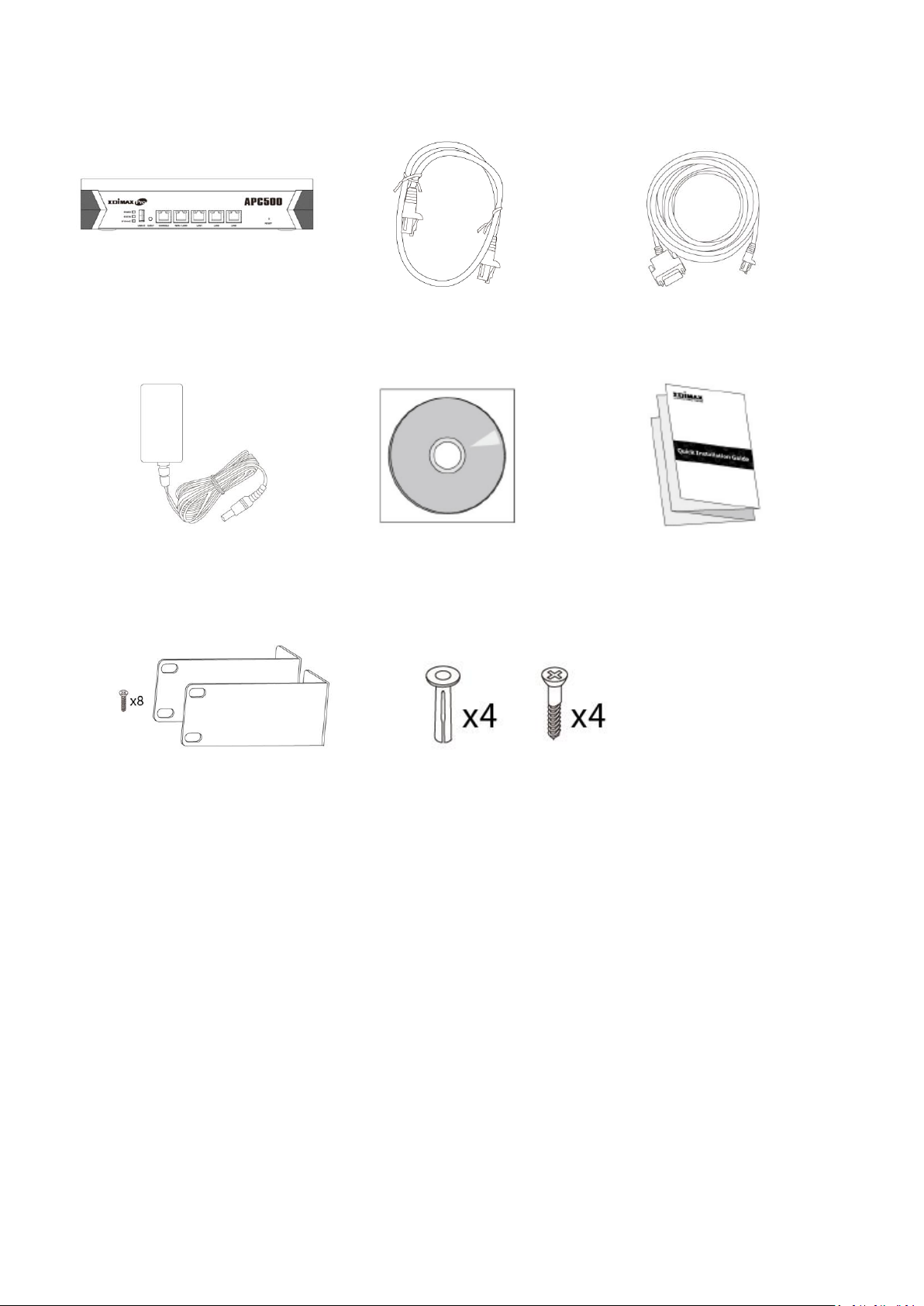
1. APC500
2. Ethernet Cable
3. Console Cable
4. Power Adapter
5. CD
6. Quick Installation Guide
7. Rack-Mount Kit
8. Wall-Mount Kit
1 2 3 4 5 6 7
8
I-1. Package Contents
2
Page 8
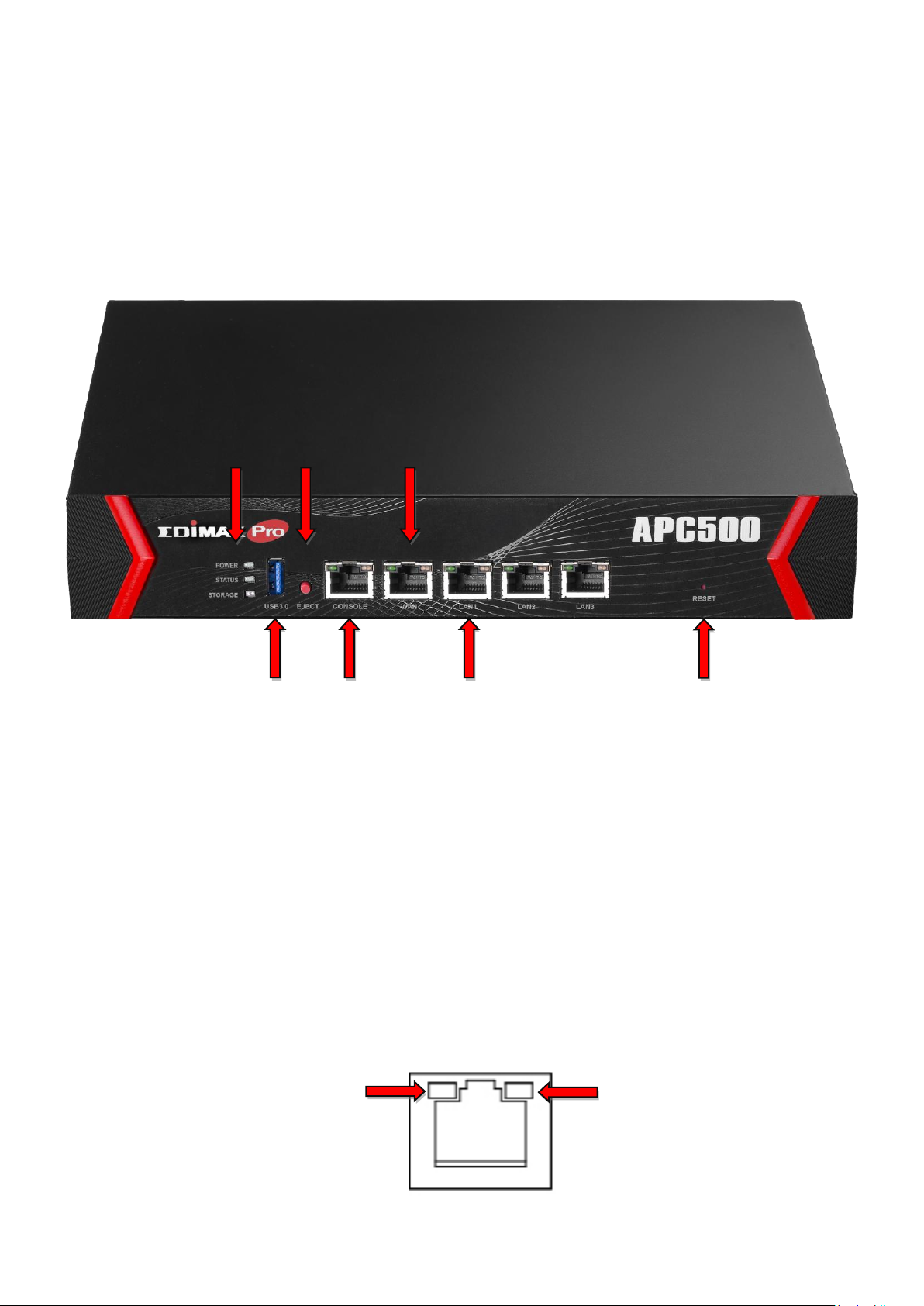
A. LEDs
B. USB 3.0
C. Eject
E. WAN/LAN port
G. Reset
D. Console
F. LAN ports
Link/ACT
Speed
I-2. System Requirements
- Existing cable/DSL modem & router
- Computer with web browser for access point configuration
I-3. Hardware Overview
A. Power, status & storage LEDs.
B. USB 3.0 port for system log and save/restore settings.
C. Eject an attached USB device.
D. Connect a management console.
E. WAN/LAN port 0.
F. LAN ports 1 – 3.
G. Reset the controller to factory default settings.
WAN & LAN ports 1 – 3 LEDs:
3
Page 9

LED
LED Color
LED Status
Description
Power
Blue
On
The controller is on.
Flashing
The controller is starting up.
Off
The controller is off.
Status
Blue
On
The controller is working properly.
Flashing
Transferring/receiving data.
Off
The controller is offline.
Storage
Blue
On
USB storage attached.
Flashing
USB activity.
Off
No USB storage attached.
Link/ACT
Green
On
Active link.
Flashing
Network activity.
Off
Inactive link.
Speed
Green
On
1000 Mbps
Off
10/100 Mbps
I-4. LED Status
I-5. Reset
If you experience problems with your controller, you can reset the device back
to its factory settings. This resets all settings back to default.
1. Press and hold the reset button on the front of the controller for at least
10 seconds.
You may need to use a pin or similar sharp object to push the
reset button.
2. Wait for the controller to restart. The controller is ready for setup when
the blue power LED is on.
4
Page 10
Baud Rate
115200
Data
8 bit
Parity
None
Stop
1 bit
Flow Control
None
I-6. Console/HyperTerminal
The controller can be configured via the “Console” port located on the access
point’s side panel using a terminal or a PC-based terminal-emulation program
(e.g. HyperTerminal).
Use a DB9 straight cable to connect the Console (RS-232 serial port) of the
APC500 and the RS-232 serial port of a terminal or PC.
Use the following configuration settings for terminal-emulation programs:
The console cable pin definition is compatible with Cisco console
cables.
5
Page 11

I-7. Safety Information
In order to ensure the safe operation of the device and its users, please read
and act in accordance with the following safety instructions.
1. The controller is designed for indoor use only; do not place the controller
outdoors.
2. Do not place the controller in or near hot/humid places, such as a kitchen
or bathroom.
3. Do not pull any connected cable with force; carefully disconnect it from the
controller.
4. Handle the controller with care. Accidental damage will void the warranty
of the controller.
5. The device contains small parts which are a danger to small children under
3 years old. Please keep the controller out of reach of children.
6. Do not place the controller on paper, cloth, or other flammable materials.
The controller may become hot during use.
7. There are no user-serviceable parts inside the controller. If you experience
problems with the controller, please contact your dealer of purchase and
ask for help.
8. The controller is an electrical device and as such, if it becomes wet for any
reason, do not attempt to touch it without switching the power supply off.
Contact an experienced electrical technician for further help.
9. If you smell burning or see smoke coming from the controller or power
adapter, then disconnect the controller and power adapter immediately, as
far as it is safely possible to do so. Call your dealer of purchase for help.
6
Page 12
II. Hardware Installation
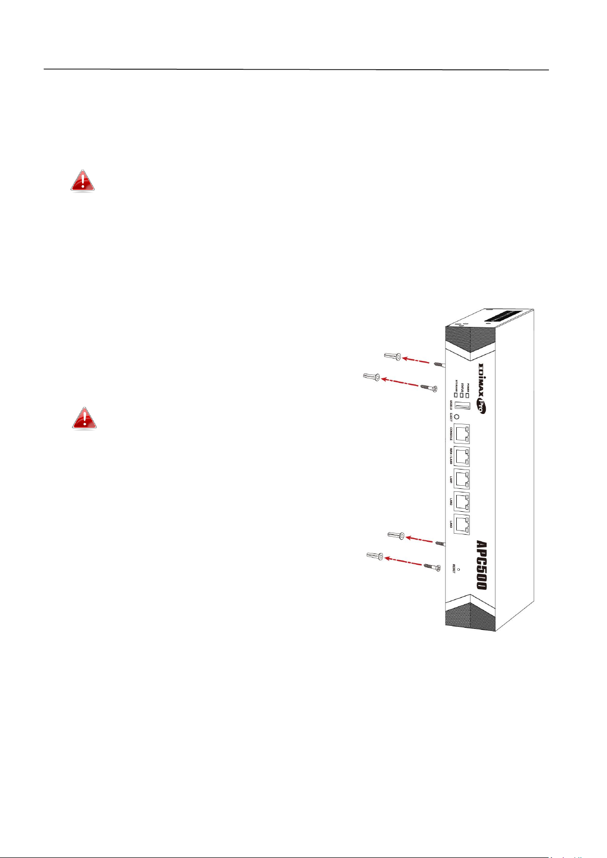
II-1. Wall Mount
The APC500 includes screws to mount your controller to a wall.
Remove the rubber feet from the underside of the APC500 by
pulling gently before using the wall mount.
1. Identify and mark correct screw positions on your selected wall.
2. Attach the APC500 to your wall using the included screws, as shown in the
diagram.
3. Ensure the APC500 is fixed to the wall
firmly and oriented correctly, with the
controller’s Edimax logo as shown in the
diagram.
Ensure your controller is securely
attached to the wall.
7
Page 13
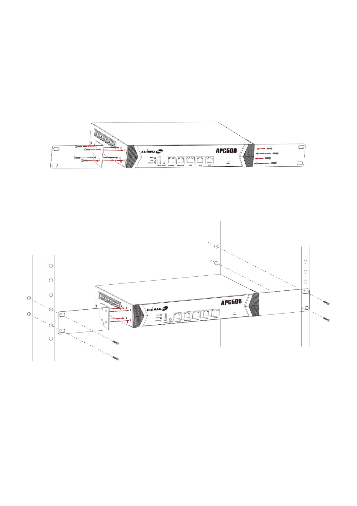
II-2. Rack Mount
The controller can be mounted in a rack which can be placed in a wiring closet
with other equipment. To install the switch, please follow these steps:
1. Attach the mounting brackets on the controller’s side panels (one on each
side) and secure them with the screws provided.
2. Use the screws provided with your equipment rack to mount the controller
on the rack and tighten it.
8
Page 14
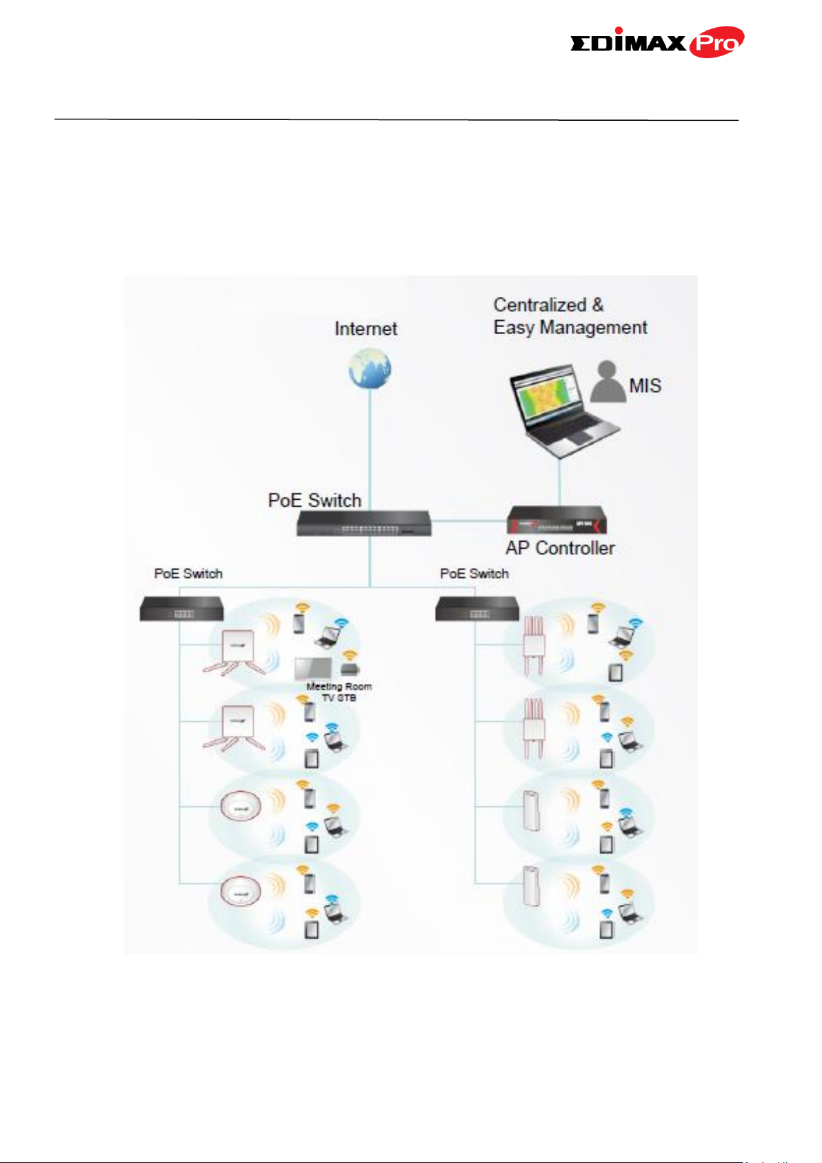
III. Quick Setup
The APC500 supports central management for up to 32 Edimax Pro access
points, reducing costs and facilitating efficient remote AP management.
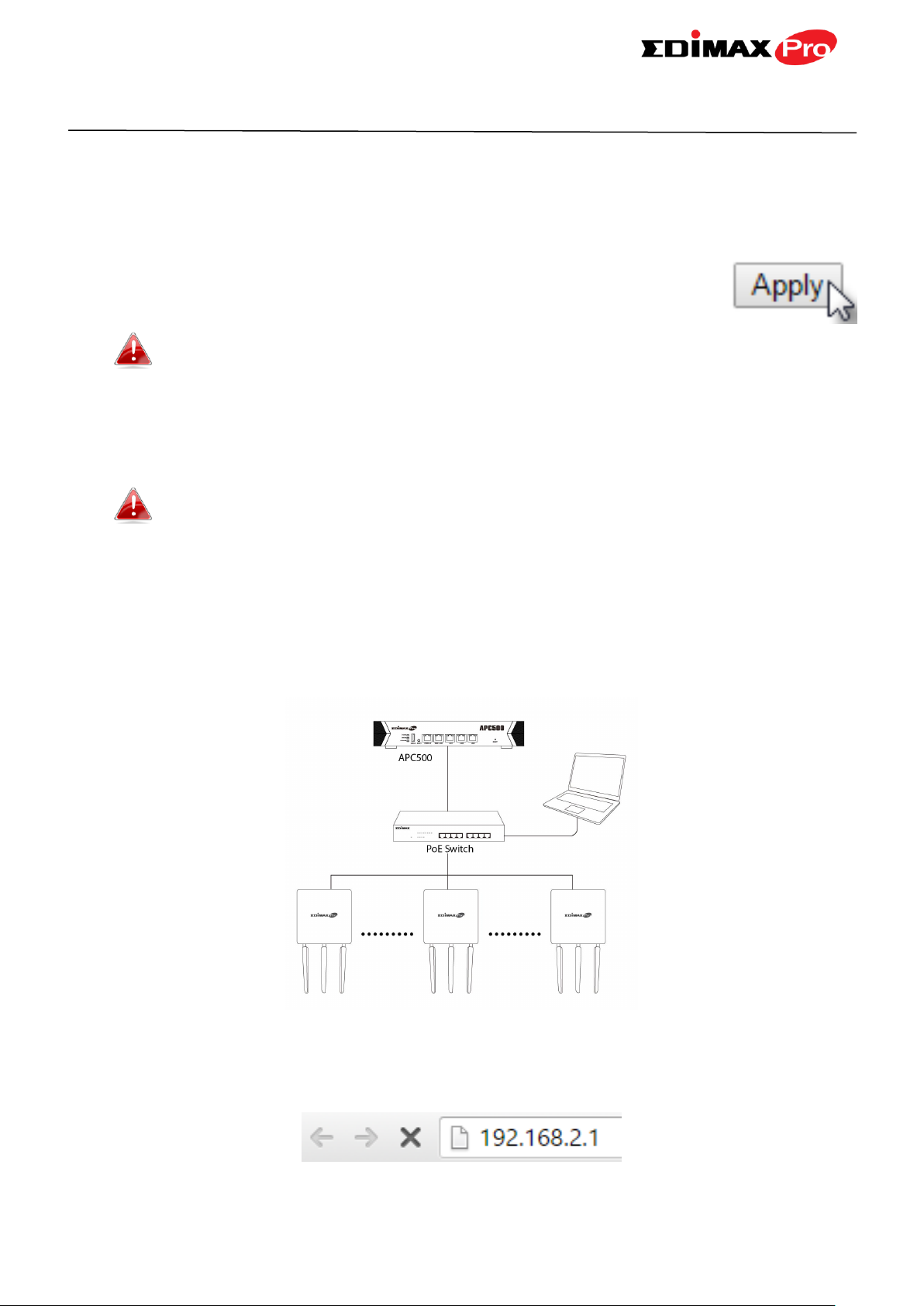
APC500 is simple to setup. An overview of a recommended network is shown
below:
9
Page 15
The APC500 Controller connects to a network via a switch or directly to a
router, and other connected Edimax Pro access points are automatically
designated as Managed APs. Using the APC500 you can configure, monitor
and manage all Managed APs (up to 32 connected by switches) from the
single AP Controller.
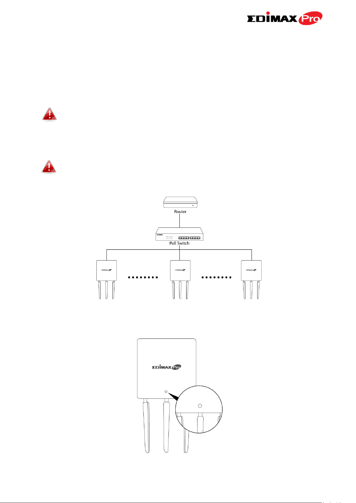
Ensure you have the latest firmware from the Edimax website for
your Edimax Pro products.
1. Connect all APs to a PoE switch which is connected to a gateway/router.
You can use your router as a DHCP server or you can later
configure your AP Controller as a DHCP server.
2. Ensure all APs are powered on and check LEDs.
10
Page 16
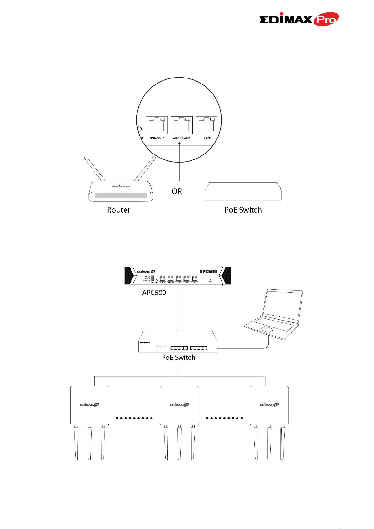
3. Connect the APC500 to the PoE switch (LAN port) or gateway/router (WAN
port) and connect the power supply.
4. Connect a computer to the APC500 using an Ethernet cable.
11
Page 17
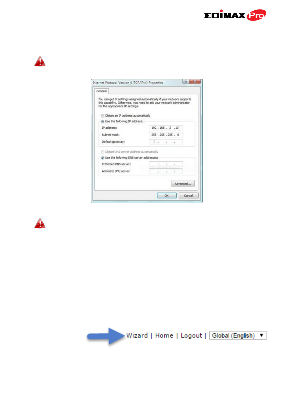
5. Open a web browser and enter the AP Controller’s IP address in the
address field. The default IP address is 192.168.2.1
Your computer’s IP address must be in the same subnet as the AP
Controller. Refer to V-1. Configuring your IP Address for help.
If you changed the AP Controller’s IP address, or if your
gateway/router uses a DHCP server, ensure you enter the correct
IP address. Refer to your gateway/router’s settings.
6. Enter the username & password to login. The default username &
password are admin & 1234.
7. You will arrive at the APC500 Dashboard. APC500 includes a wizard to
quickly setup the LAN IP address, admin login & time/date settings for the
APC500, as well as SSID & security for Managed APs. Click “Wizard” in the
top right corner to begin.
12
Page 18
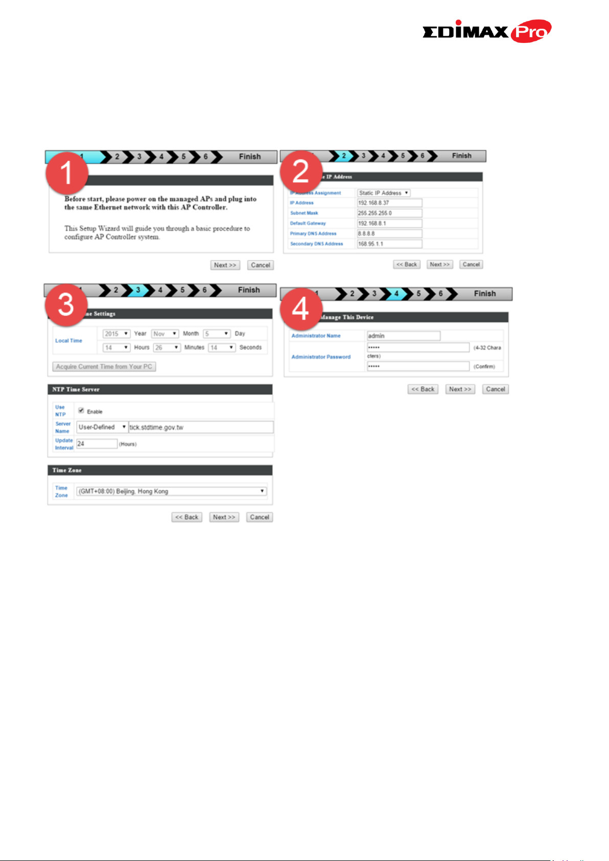
8. Follow the instructions on-screen to complete Steps 1 - 7 and click “Finish”
to save the settings. The wizard will help you set up LAN IP address,
2.4GHz & 5GHz SSID and security, administrator name & password, time &
date settings and Managed APs.
13
Page 19
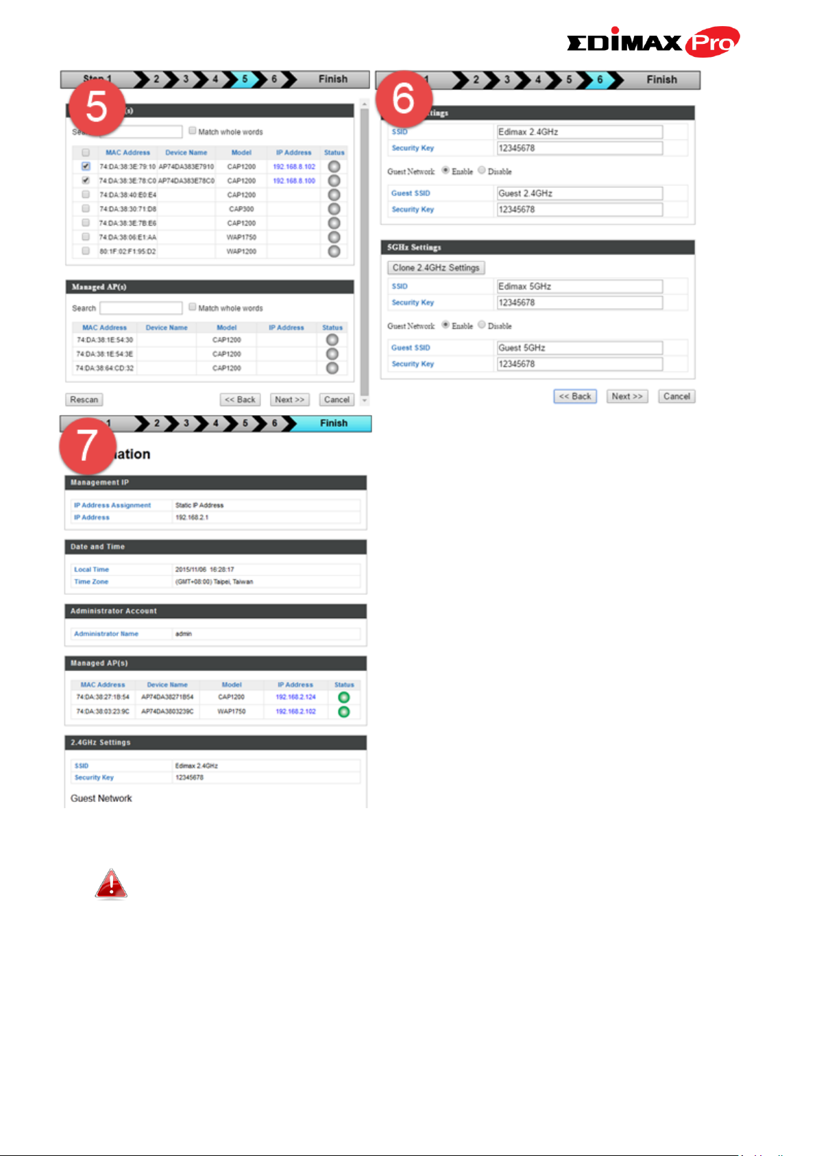
If any of your Managed APs are not found during Step 5 Select
Free APs, reset the Managed AP to its factory default settings.
Refer to the AP’s user manual for help.
9. Your APC500 Controller & Managed APs should be fully functional with all
of the basic settings configured. Use the top menu to navigate around
Edimax Pro NMS (Network Management Suite) settings.
14
Page 20

Use Dashboard, Zone Plan, NMS Monitor & NMS Settings to configure
Managed APs.
Use Local Network & Local Settings to configure your APC500.
15
Page 21
IV. Software Layout
The top menu features 7 panels: Dashboard, Zone Plan, NMS Monitor, NMS
Settings, Local Network, Local Settings & Toolbox.
Dashboard
The Dashboard panel displays an overview of your network and key system
information, with quick links to access configuration options for Managed APs
and Managed AP groups. Each panel can be refreshed, collapsed or moved
according to your preference.
16
Page 22
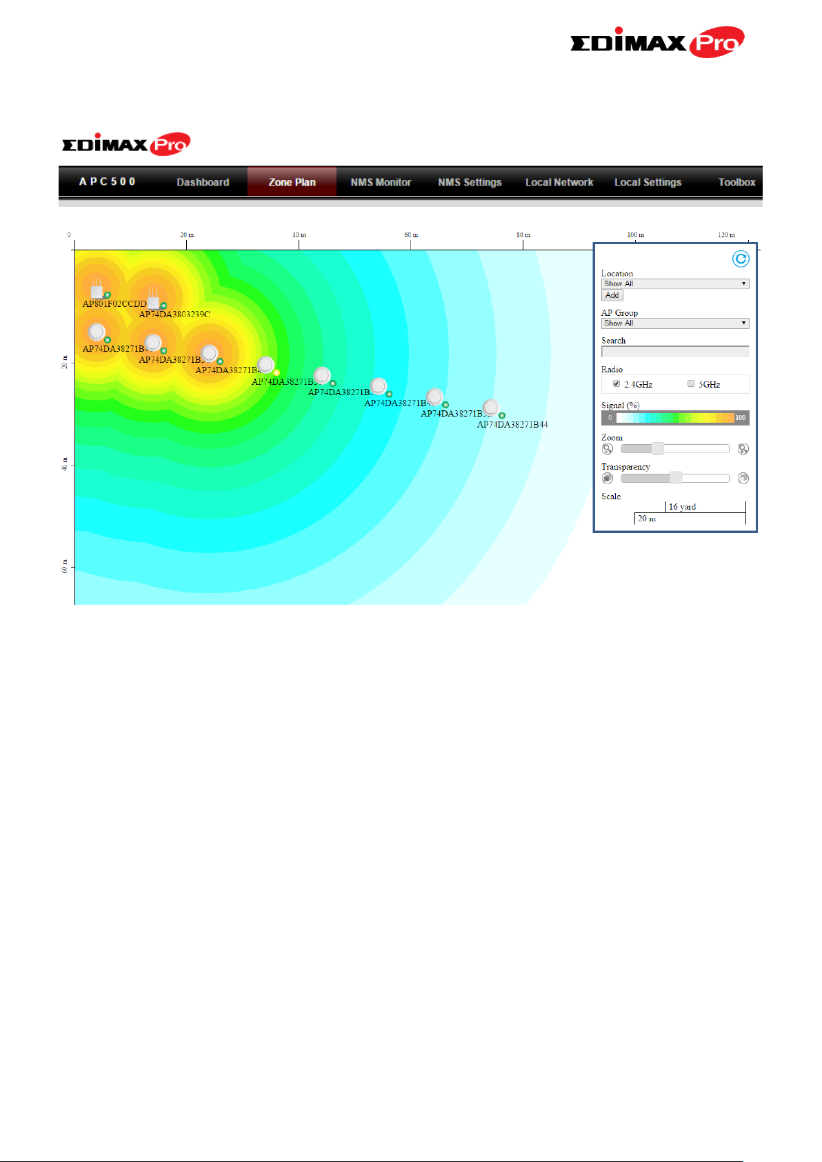
Zone Plan
Zone Plan displays a customizable live map of Managed APs for a visual
representation of your network coverage. Each AP icon can be moved around
the map, and a background image can be uploaded for user-defined location
profiles using NMS Settings Zone Edit. Options can be configured using the
menu on the right side and signal strength is displayed for each AP.
17
Page 23
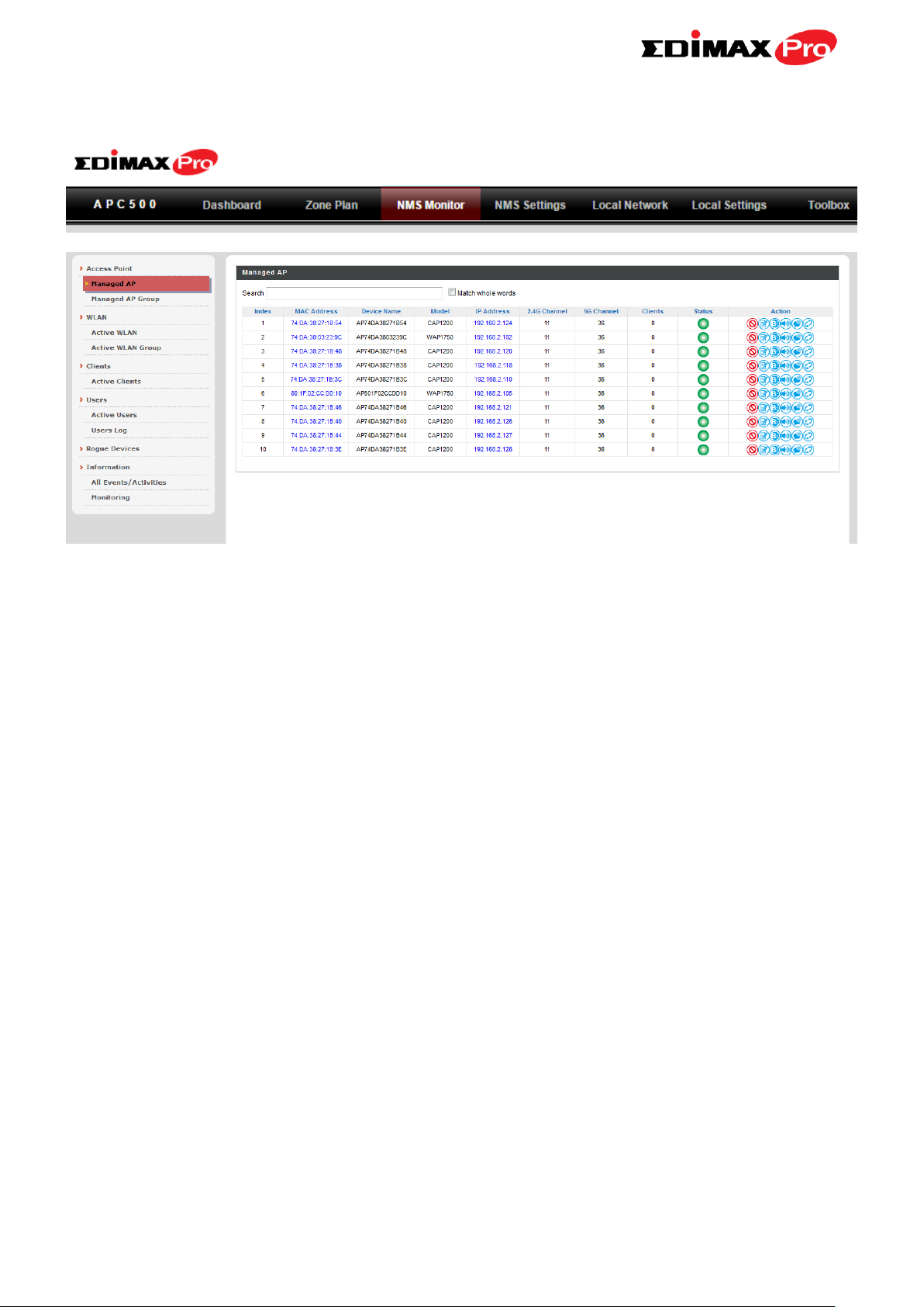
NMS Monitor
The NMS Monitor panel provides more detailed monitoring information
about the AP Array than found on the Dashboard, grouped according to
categories in the menu down the left side.
18
Page 24
NMS Settings
NMS Settings provides extensive configuration options for the AP Array. You
can manage each access point, assign access points into groups, manage
WLAN, RADIUS, guest network, guest network, users and scheduling settings
as well as upgrade firmware across multiple access points. The Zone Plan can
also be configured using “Zone Edit”.
19
Page 25
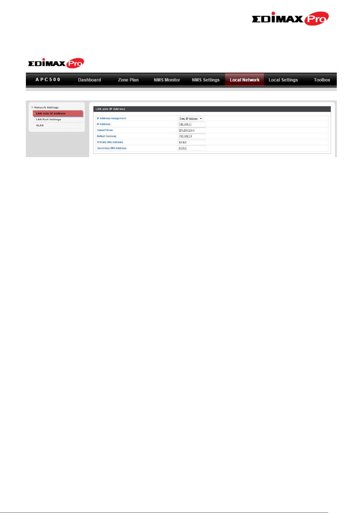
Local Network
Local Network settings are for your AP Controller. You can configure the IP
address and DHCP server of the AP Controller in addition to LAN Port and
VLAN settings.
20
Page 26
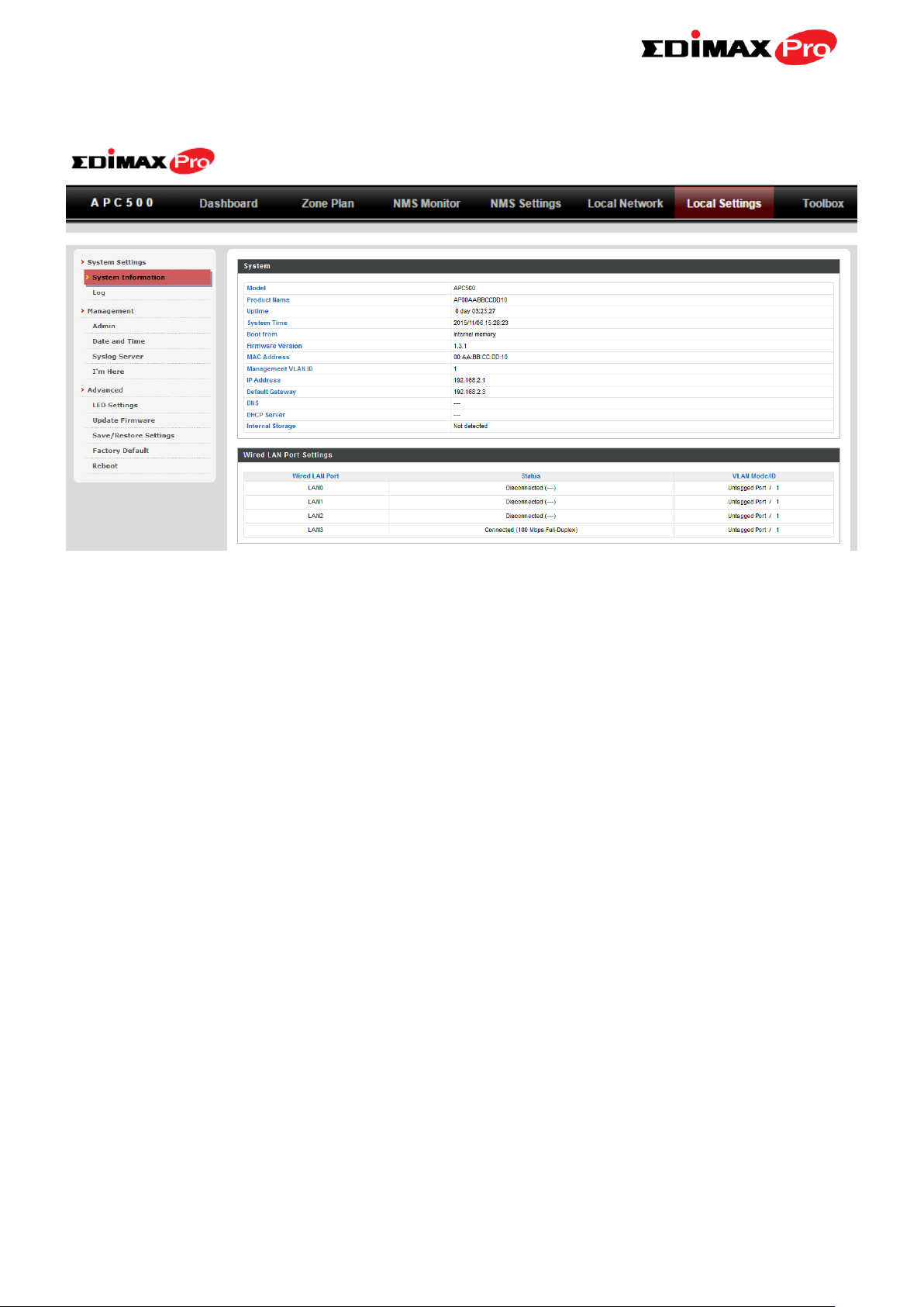
Local Settings
Local Settings are for your AP Controller. You can view basic system settings
and logs specifically for the AP Controller, as well as other management
settings such as date/time, admin accounts, firmware and reset.
21
Page 27
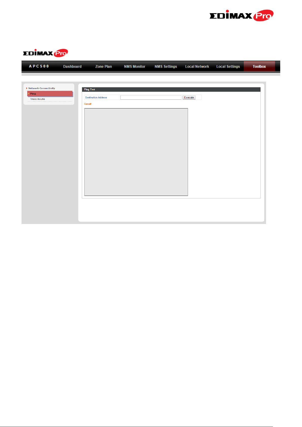
Toolbox
The Toolbox panel provides two network diagnostic tools: ping and
traceroute.
22
Page 28
V. Features
Descriptions of the functions of each main panel Dashboard, Zone Plan, NMS
Monitor, NMS Settings, Local Network, Local Settings & Toolbox can be found
below. When using Edimax NMS, click “Apply” to save changes:
Screenshots displayed are examples. The information shown on
your screen will vary depending on your configuration.
V-1. LOGIN, LOGOUT & RESTART
It is recommended that you login to the AP Controller to make
configurations to Managed APs.
LOGIN
1. Connect a computer to the designated AP Controller using an Ethernet
cable:
2. Open a web browser and enter the AP Controller’s IP address in the
address field. The default IP address is 192.168.2.1
23
Page 29
Your computer’s IP address must be in the same subnet as the AP
Controller. Refer to VI-1. Configuring your IP Address for more
help.
If you changed the AP Controller’s IP address, or if your
gateway/router uses a DHCP server, ensure you enter the correct
IP address. Refer to your gateway/router’s settings.
If using a DHCP server on the network, it is advised to use your
DHCP server’s settings to assign the AP Controller a static IP
address.
3. Enter the username & password to login. The default username &
password are admin & 1234.
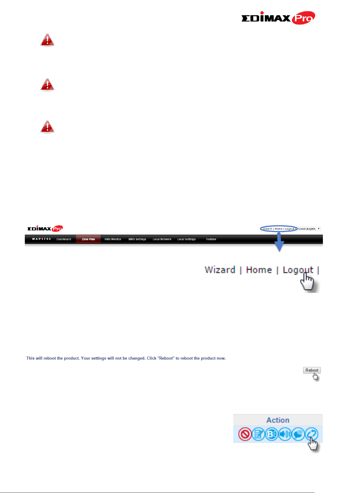
LOGOUT
To logout from Edimax NMS, click “Logout” in the top right corner:
RESTART
You can restart your AP Controller or any Managed AP using Edimax NMS. To
restart your AP Controller go to Local Settings Advanced Reboot and
click “Reboot”.
To restart Managed APs click the Restart icon for the specified AP on the
Dashboard:
24
Page 30
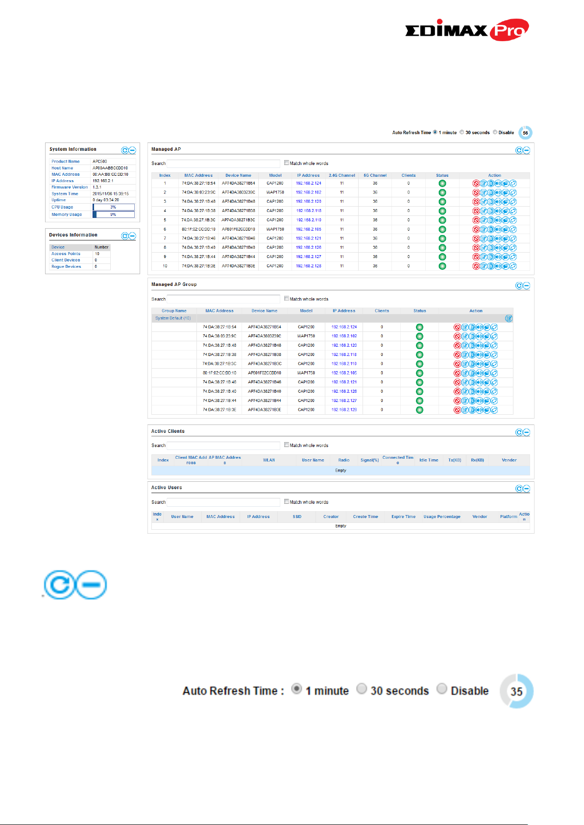
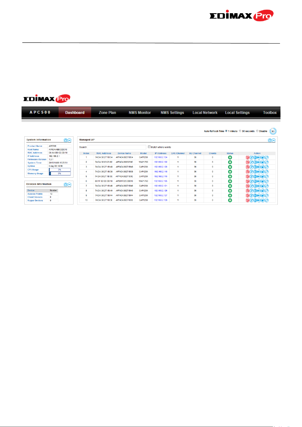
V-2. DASHBOARD
The dashboard displays an overview of your AP array:
Use the blue icons above to refresh or collapse each panel in the dashboard.
Click and drag to move a panel to suit your preference. You can set the
dashboard to auto-refresh every 1 minute, 30 seconds or disable auto-refresh:
25
Page 31

V-2-1. System Information
System Information displays information about the AP Controller: Product
Name (model), Host Name, MAC Address, IP Address, Firmware Version,
System Time and Uptime (time the access point has been on), CPU Usage &
Memory Usage.
V-2-2. Devices Information
Devices Information is a summary of the number of all devices in the local
network: Access Points, Clients Connected, and Rogue (unidentified) Devices.
26
Page 32

V-2-3. Managed AP
Managed AP displays information about each Managed AP in the local
network: Index (reference number), MAC Address, Device Name, Model, IP
Address, 2.4GHz & 5GHz Wireless Channel Number, No. of Clients connected
to each access point, and Status (connected, connecting or disconnected).
The search function can be used to locate a specific Managed AP. Type in the
search box and the list will update:
The Status icon displays grey (disconnected), yellow (connecting) or green
(connected) for each Managed AP.
Each Managed AP has “Action” icons with the following functions:
1. Disallow
Remove the Managed AP from the AP array and disable connectivity.
2. Edit
Edit various settings for the Managed AP (refer to V-5-1. Access Point).
3. Blink LED
The Managed AP’s LED will flash temporarily to help identify & locate
access points.
27
Page 33

4. Buzzer
The Managed AP’s buzzer will sound temporarily to help identify & locate
access points.
5. Network Connectivity
Go to the “Network Connectivity” panel to perform a ping or traceroute.
6. Restart
Restarts the Managed AP.
V-2-4. Managed AP Group
Managed APs can be grouped according to your requirements. Managed AP
Group displays information about each Managed AP group in the local
network: Group Name, MAC Address, Device Name, Model, IP Address, No. of
Clients connected to each access point, and Status (connected or
disconnected).
To edit Managed AP Groups go to NMS Settings Access Point (refer to
V-5-1. Access Point).
The search function can be used to locate a specific Managed AP Group. Type
in the search box and the list will update:
The Status icon displays grey (disconnected), yellow (connecting) or green
(connected) for each individual Managed AP.
Each Managed AP has “Action” icons with the following functions:
28
Page 34

1. Disallow
Remove the Managed AP from the AP array and disable connectivity.
2. Edit
Edit various settings for the Managed AP (refer to V-5-1. Access Point)
3. Blink LED
The Managed AP’s LED will flash temporarily to help identify & locate
access points.
4. Buzzer
The Managed AP’s buzzer will sound temporarily to help identify & locate
access points.
5. Network Connectivity
Go to the “Network Connectivity” panel to perform a ping or traceroute.
6. Restart
Restarts the Managed AP.
V-2-5. Active Clients
Active Clients displays information about each client in the local network:
Index (reference number), Client MAC Address, AP MAC Address, WLAN, User
Name, Radio (frequency), Signal Strength, Connected Time, Idle Time, Tx & Rx
(data transmitted and received) and Vendor of the client device.
The search function can be used to locate a specific client. Type in the search
box and the list will update:
29
Page 35

V-2-6. Active Users
Active Users displays information about each user in the local network via
guest portals: Index (reference number), User Name, MAC Address, IP Address,
SSID, Creator, Create Time, Expire Time, Usage Percentage, Vendor & Platform
of the user device.
The search function can be used to locate a specific client. Type in the search
box and the list will update:
30
Page 36

V-3. ZONE PLAN
The Zone Plan can be fully customized to match your network environment.
You can move the AP icons and select different location images (upload
location images in NMS Settings Zone Edit) to create a visual map of your
AP array.
Use the menu on the right side to make adjustments and mouse-over an AP
icon in the zone map to see more information. Click an AP icon in the zone
map to select it and display action icons:
31
Page 37

Click and drag an AP icon to move the icon around the zone map. The signal
Location
Select a pre-defined location from the drop
down menu. When you upload a location
image in NMS Settings Zone Edit, it will be
available for selection here.
AP Group
You can select an AP Group to display in the
zone map. Edit AP Groups in NMS Settings
Access Point.
Search
Use the search box to quickly locate an AP.
Radio
Use the checkboxes to display APs according
to 2.4GHz or 5GHz wireless radio frequency.
Signal
Signal strength key for the signal strength
display around each AP in the zone map.
Zoom
Use the slider to adjust the zoom level of the
map.
Transparency
Use the slider to adjust the transparency of
location images.
Scale
Zone map scale.
Device/Number
Displays number and type of devices in the
zone map.
strength for each AP is displayed according to the “Signal” key in the menu on
the right side:
32
Page 38

V-4. NMS MONITOR
Status Icons
Icon
Color
Status
Definition
Grey
Disconnected
Managed AP is disconnected. Please
check the network connection and ensure
the Managed AP is in the same IP subnet
as the AP Controller.
Red
Authentication
Failed
System security must be the same for all
access points in the AP array. Please
check security settings (refer to V-5-12-1.
V-4-1. Access Point
V-4-1-1. Managed AP
Displays information about each Managed AP in the local network: Index
(reference number), MAC Address, Device Name, Model, IP Address, 2.4GHz &
5GHz Wireless Channel Number, No. of Clients connected to each access point,
and Status (connected, connecting or disconnected).
The search function can be used to locate a specific Managed AP. Type in the
search box and the list will update:
The Status icon displays the status of each Managed AP.
33
Page 39

Or
Incompatible
NMS Version
System Security).
Access points must use the same version
of Edimax NMS: the managed AP will not
be able to make configurations. Please
use the AP Controller’s firmware upgrade
function (refer to V-5-11. Firmware
Upgrade).
Orange
Configuring or
Upgrading
Please wait while the Managed AP makes
configurations or while the firmware is
upgrading.
Yellow
Connecting
Please wait while Managed AP is
connecting.
Green
Connected
Managed AP is connected.
Blue
Waiting for
Approval
Managed AP is waiting for approval.
Refer to V-5-1. Access Point: Auto
Approval. Note: 32 Managed APs are
supported. Additional APs will display this
status until an existing Managed AP is
removed.
Each Managed AP has “Action” icons with the following functions:
1. Disallow
Remove the Managed AP from the AP array and disable connectivity.
1. Edit
Edit various settings for the Managed AP (refer to V-5-1. Access Point).
2. Blink LED
The Managed AP’s LED will flash temporarily to help identify & locate
access points.
34
Page 40

3. Buzzer
The Managed AP’s buzzer will sound temporarily to help identify & locate
access points.
4. Network Connectivity
Go to the “Network Connectivity” panel to perform a ping or traceroute.
5. Restart
Restarts the Managed AP.
V-4-1-2. Managed AP Group
Managed APs can be grouped according to your requirements. Managed AP
displays information about each Managed AP in the local network: Index
(reference number), MAC Address, Device Name, Model, IP Address, 2.4GHz &
5GHz Wireless Channel Number, No. of Clients connected to each access point,
and Status (connected, connecting or disconnected).
To edit Managed AP Groups go to NMS Settings Access Point (refer to
V-5-1. Access Point).
The search function can be used to locate a specific Managed AP Group. Type
in the search box and the list will update:
The Status icon displays grey (disconnected), red (authentication
failed/incompatible NMS version), orange (upgrading firmware), yellow
35
Page 41

(connecting), green (connected) or blue (waiting for approval) for each
individual Managed AP. Refer to V-4-1-1. Managed AP: Status Icons for full
descriptions.
Each Managed AP has “Action” icons with the following functions:
2. Disallow
Remove the Managed AP from the AP array and disable connectivity.
3. Edit
Edit various settings for the Managed AP (refer to V-5-1. Access Point).
4. Blink LED
The Managed AP’s LED will flash temporarily to help identify & locate
access points.
5. Buzzer
The Managed AP’s buzzer will sound temporarily to help identify & locate
access points.
6. Network Connectivity
Go to the “Network Connectivity” panel to perform a ping or traceroute.
7. Restart
Restarts the Managed AP.
36
Page 42

V-4-2. WLAN
V-4-2-1. Active WLAN
Displays information about each SSID in the AP Array: Index (reference
number), Name/SSID, VLAN ID, Authentication, Encryption, IP Address and
Additional Authentication.
To configure encryption and VLANs for Managed APs go to NMS Settings
WLAN.
The search function can be used to locate a specific SSID. Type in the search
box and the list will update:
37
Page 43

V-4-2-2. Active WLAN Group
WLAN groups can be created according to your preference. Active WLAN
Group displays information about WLAN group: Group Name, Name/SSID,
VLAN ID, Authentication, Encryption, IP Address and Additional
Authentication.
The search function can be used to locate a specific Active WLAN Group. Type
in the search box and the list will update:
V-4-3. Clients
V-4-3-1. Active Clients
Displays information about clients currently connected to the AP Array: Index
(reference number), Client MAC Address, AP MAC Address, WLAN (SSID), User
Name, Radio (2.4GHz or 5GHz), Signal Strength received by Client, Connected
Time, Idle Time, Tx & Rx (Data transmitted and received by Client in KB)..
You can set or disable the auto-refresh time for the client list or click
“Refresh” to manually refresh.
The search function can be used to locate a specific client. Type in the search
box and the list will update:
38
Page 44

V-4-4. Users
V-4-4-1. Active Users
Displays information about each user in the local network via guest portals:
Index (reference number), User Name, MAC Address, IP Address, SSID, Creator,
Create Time, Expire Time, Usage Percentage, Vendor & Platform of the user
device.
The search function can be used to locate a specific client. Type in the search
box and the list will update:
V-4-4-2. Users Log
Displays a detailed information log of users and activity on the network via
guest portals: ID, Date and Time of entry, Category of entry, Severity, Users,
Event/Activities details.
39
Page 45

The search function can be used to locate a specific client. Type in the search
box and the list will update:
V-4-5. Rogue Devices
Rogue access point detection can identify any unauthorized access points
which may have been installed in the network.
Click “Start” to scan for rogue devices:
Unknown Rogue Devices displays information about rogue devices discovered
during the scan: Index (reference number), Channel, SSID, MAC Address,
Security, Signal Strength, Type, Vendor and Action.
The search function can be used to locate a known rogue device. Type in the
search box and the list will update:
40
Page 46

V-4-6. Information
V-4-6-1. All Events/Activities
Displays a log of time-stamped events for each access point in the Array – use
the drop down menu to select an access point and view the log.
41
Page 47

V-4-6-2. Monitoring
Displays graphical monitoring information about access points in the Array for
2.4GHz & 5GHz: Traffic Tx (data transmitted in MB), Traffic Rx (data received
in MB), No. of Clients, Wireless Channel, Tx Power (wireless radio power), CPU
Usage and Memory Usage.
Use the drop down menus to select an access point and date.
You can set or disable the auto-refresh time for the data:
42
Page 48

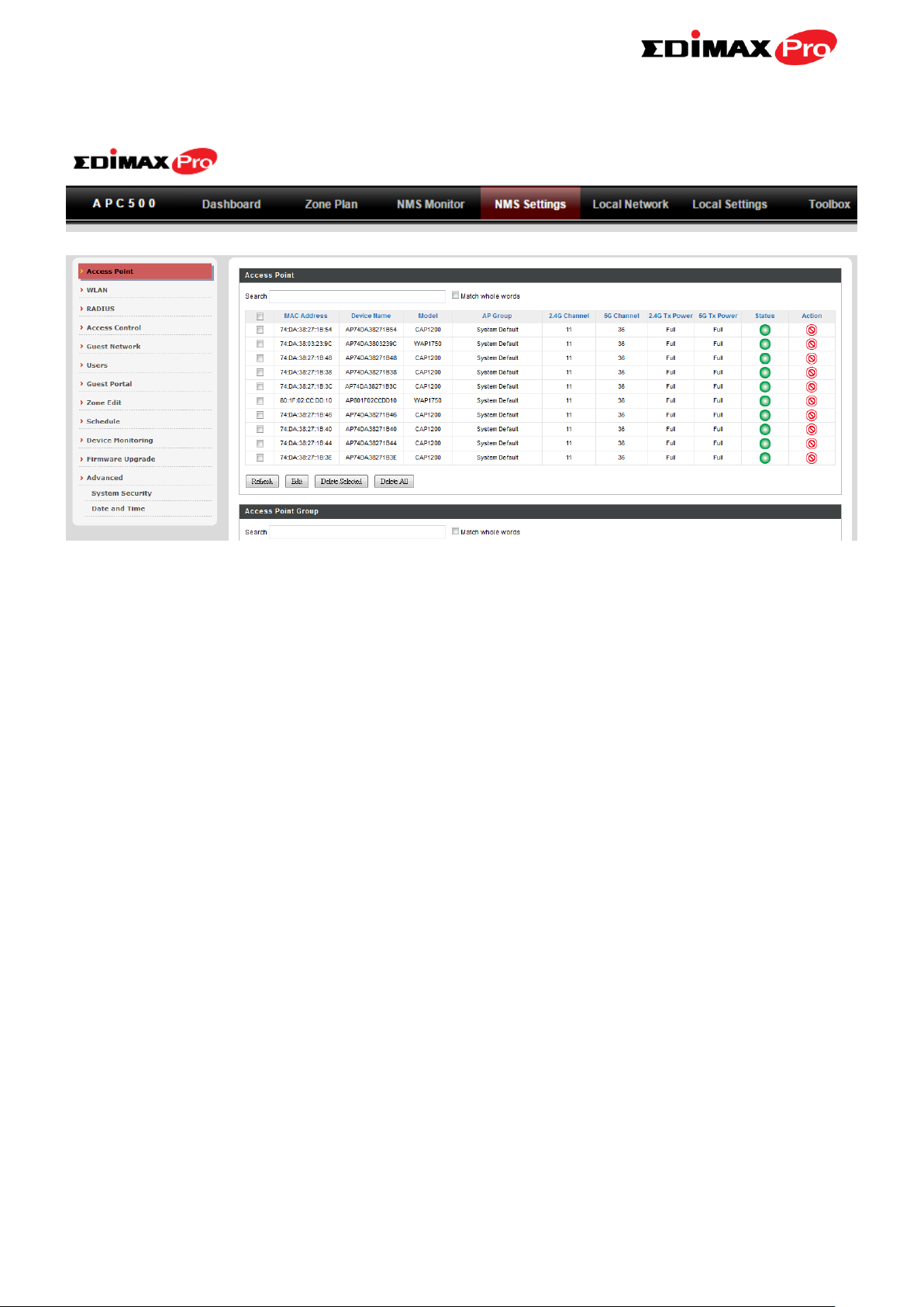
V-5. NMS Settings
V-5-1. Access Point
Displays information about each access point and access point group in the
local network and allows you to edit access points and edit or add access
point groups.
The search function can be used to locate an access point or access point
group. Type in the search box and the list will update:
The Status icon displays grey (disconnected), red (authentication
failed/incompatible NMS version), orange (upgrading firmware), yellow
(connecting), green (connected) or blue (waiting for approval) for each
individual Managed AP. Refer to V-4-1-1. Managed AP: Status Icons for full
descriptions.
43
Page 49

Access Point Settings
Auto Approve
Enable or disable Auto Approve for all
Managed APs.
The “Action” icons enable you to allow or disallow an access point:
Select an access point or access point group using the
check-boxes and click “Edit” to make configurations, or click
“Add” to add a new access point group:
The Access Point Settings panel can enable or disable Auto
Approve for all Managed APs. When enabled, Managed APs will automatically
join the AP Array with the Controller AP. When disabled, Managed APs must
be manually approved to join the AP Array with the Controller AP.
To manually approve a Managed AP, use the allow “Action” icon for the
specified access point:
Edit Access Point
Configure your selected access point on your LAN. You can set the access
point as a DHCP client or specify a static IP address for your access point, and
assign the access point to an AP group, as well as edit 2.4GHz & 5GHz wireless
radio settings. An events log is displayed at the bottom of the page.
You can also use Profile Settings to assign the access point to WLAN, Guest
Network, RADIUS and Access Control groups independently from Access Point
Group settings.
Check the “Override Group Settings” box to use different individual settings
for access points assigned to AP Groups:
44
Page 50

Basic Settings
Name
Edit the access point name. The default name
is AP + MAC address.
Description
Enter a description of the access point for
reference e.g. 2nd Floor Office.
MAC Address
Displays MAC address.
AP Group
Use the drop down menu to assign the AP to
an AP Group. You can edit AP Groups from
the NMS Settings Access Point page.
IP Address
Assignment
Select “DHCP Client” for your access point to
be assigned a dynamic IP address from your
router’s DHCP server, or select “Static IP” to
manually specify a static/fixed IP address for
your access point (below). Check the box
“Override Group Setting” if the AP is a
member of an AP Group and you wish to use
a different setting than the AP Group setting.
IP Address
Specify the IP address here. This IP address
45
Page 51

will be assigned to your access point and will
replace the default IP address.
Subnet Mask
Specify a subnet mask. The default value is
255.255.255.0
Default Gateway
For DHCP users, select “From DHCP” to get
default gateway from your DHCP server or
“User-Defined” to enter a gateway manually.
For static IP users, the default value is blank.
Primary DNS
DHCP users can select “From DHCP” to get
primary DNS server’s IP address from DHCP or
“User-Defined” to manually enter a value. For
static IP users, the default value is blank.
Secondary DNS
DHCP users can select “From DHCP” to get
secondary DNS server’s IP address from DHCP
or “User-Defined” to manually enter a value.
For static IP users, the default value is blank.
VLAN Settings
Wired LAN Port
Identifies LAN port 1 or 2.
VLAN Mode
Select “Tagged Port” or “Untagged Port” for
specified LAN interface.
VLAN ID
Set a VLAN ID for specified interface, if
“Untagged Port” is selected.
Management VLAN
VLAN ID
Check ‘Override Default Setting’ to specify the
VLAN ID of the management VLAN. Only the
hosts belonging to the same VLAN can manage
the device.
46
Page 52

Radio Settings
Domain
Set the regulatory domain for the access
point’s wireless channels for each frequency.
Wireless
Enable or disable the access point’s 2.4GHz or
5GHz wireless radio. When disabled, no SSIDs
on that frequency will be active.
Band
Select the wireless standard used for the
access point. Combinations of 802.11b,
802.11g, 802.11n & 802.11ac can be selected.
Auto Pilot
Enable/disable auto channel selection. Auto
channel selection will automatically set the
wireless channel for the access point’s 2.4GHz
or 5GHz frequency based on availability and
potential interference. When disabled, select
a channel manually.
Auto Pilot Range
Select a range from which the auto channel
47
Page 53

setting (above) will choose a channel.
Auto Pilot Interval
Specify a frequency for how often the auto
channel setting will check/reassign the
wireless channel. Check/uncheck the “Change
channel even if clients are connected” box
according to your preference.
Channel Bandwidth
Set the channel bandwidth or use Auto
(automatically select based on interference
level).
BSS BasicRateSet
Set a Basic Service Set (BSS) rate: this is a
series of rates to control communication
frames for wireless clients.
Advanced Settings
Contention Slot
Select “Short” or “Long” – this value is used for
contention windows.
Preamble Type
Set the wireless radio preamble type. The
preamble type in 802.11 based wireless
communication defines the length of the CRC
(Cyclic Redundancy Check) block for
communication between the access point and
roaming wireless adapters. The default value is
“Short Preamble”.
Guard Interval
Set the guard interval. A shorter interval can
improve performance.
802.11g Protection
Enable/disable 802.11g protection, which
increases reliability but reduces bandwidth
(clients will send Request to Send (RTS) to
access point, and access point will broadcast
Clear to Send (CTS), before a packet is sent
from client.)
These settings are for experienced users only. Please do not change any of the
values on this page unless you are already familiar with these functions.
Changing these settings can adversely affect the performance of
your access point.
48
Page 54

802.11n Protection
Enable/disable 802.11n protection, which
increases reliability but reduces bandwidth
(clients will send Request to Send (RTS) to
access point, and access point will broadcast
Clear to Send (CTS), before a packet is sent
from client.)
DTIM Period
Set the DTIM (delivery traffic indication
message) period value of the wireless radio.
The default value is 1.
RTS Threshold
Set the RTS threshold of the wireless radio. The
default value is 2347.
Fragment
Threshold
Set the fragment threshold of the wireless
radio. The default value is 2346.
Multicast Rate
Set the transfer rate for multicast packets or
use the “Auto” setting.
Tx Power
Set the power output of the wireless radio. You
may not require 100% output power. Setting a
lower power output can enhance security since
potentially malicious/unknown users in distant
areas will not be able to access your signal.
Beacon Interval
Set the beacon interval of the wireless radio.
The default value is 100.
Station idle
timeout
Set the interval for keepalive messages from
the access point to a wireless client to verify if
the station is still alive/active.
Profile Settings
WLAN Group
Assign the access point’s 2.4GHz or 5GHz
SSID(s) to a WLAN Group. You can edit WLAN
groups in NMS Settings WLAN.
Guest Network
Group
Assign the access point’s 2.4GHz or 5GHz
SSID(s) to a Guest Network Group. You can
edit Guest Network groups in NMS Settings
49
Page 55

Guest Network.
RADIUS Group
Assign the access point’s 2.4GHz SSID(s) to a
RADIUS group. You can edit RADIUS groups in
NMS Settings RADIUS.
Access Control
Group
Assign the access point’s 2.4GHz SSID(s) to a
RADIUS group. You can edit RADIUS groups in
NMS Settings Access Control
50
Page 56

Add/Edit Access Point Group
Basic Group Settings
Name
Edit the access point group name.
Description
Enter a description of the access point group
for reference e.g. 2nd Floor Office Group.
VLAN Group Settings
Wired LAN Port
Identifies LAN port 1 or 2.
VLAN Mode
Select “Tagged Port” or “Untagged Port” for
specified LAN interface.
VLAN ID
Set a VLAN ID for specified interface, if
“Untagged Port” is selected.
Management VLAN
VLAN ID
Check ‘Override Default Setting’ to specify the
VLAN ID of the management VLAN. Only the
hosts belonging to the same VLAN can manage
Configure your selected access point group. Access point group settings apply
to all access points in the group, unless individually set to override group
settings.
You can use Profile Group Settings to assign the access point group to WLAN,
Guest Network, RADIUS and Access Control groups.
The Group Settings panel can be used to quickly move access points between
existing groups: select an access point and use the drop down menu or search
to select access point groups and use << and >> arrows to move APs between
groups.
51
Page 57

the device.
Radio Group Settings
Domain
Set the regulatory domain for the access
point’s wireless channels for each frequency.
Wireless
Enable or disable the access point group’s
2.4GHz or 5GHz wireless radio. When
disabled, no SSIDs on that frequency will be
active.
Band
Select the wireless standard used for the
access point group. Combinations of 802.11b,
802.11g, 802.11n & 802.11ac can be selected.
Auto Pilot
Enable/disable auto channel selection. Auto
channel selection will automatically set the
wireless channel for the access point group’s
2.4GHz or 5GHz frequency based on
availability and potential interference. When
disabled, select a channel manually.
Auto Pilot Range
Select a range from which the auto channel
52
Page 58

setting (above) will choose a channel.
Auto Pilot Interval
Specify a frequency for how often the auto
channel setting will check/reassign the
wireless channel. Check/uncheck the “Change
channel even if clients are connected” box
according to your preference.
Channel Bandwidth
Set the channel bandwidth or use Auto
(automatically select based on interference
level).
BSS BasicRateSet
Set a Basic Service Set (BSS) rate: this is a
series of rates to control communication
frames for wireless clients.
Advanced Settings
Contention Slot
Select “Short” or “Long” – this value is used for
contention windows.
Preamble Type
Set the wireless radio preamble type. The
preamble type in 802.11 based wireless
communication defines the length of the CRC
(Cyclic Redundancy Check) block for
communication between the access point and
roaming wireless adapters. The default value is
“Short Preamble”.
Guard Interval
Set the guard interval. A shorter interval can
improve performance.
802.11g Protection
Enable/disable 802.11g protection, which
increases reliability but reduces bandwidth
(clients will send Request to Send (RTS) to
access point, and access point will broadcast
Clear to Send (CTS), before a packet is sent
from client.)
These settings are for experienced users only. Please do not change any of the
values on this page unless you are already familiar with these functions.
Changing these settings can adversely affect the performance of
your access points.
53
Page 59

802.11n Protection
Enable/disable 802.11n protection, which
increases reliability but reduces bandwidth
(clients will send Request to Send (RTS) to
access point, and access point will broadcast
Clear to Send (CTS), before a packet is sent
from client.)
DTIM Period
Set the DTIM (delivery traffic indication
message) period value of the wireless radio.
The default value is 1.
RTS Threshold
Set the RTS threshold of the wireless radio. The
default value is 2347.
Fragment
Threshold
Set the fragment threshold of the wireless
radio. The default value is 2346.
Multicast Rate
Set the transfer rate for multicast packets or
use the “Auto” setting.
Tx Power
Set the power output of the wireless radio. You
may not require 100% output power. Setting a
lower power output can enhance security since
potentially malicious/unknown users in distant
areas will not be able to access your signal.
Beacon Interval
Set the beacon interval of the wireless radio.
The default value is 100.
Station idle
timeout
Set the interval for keepalive messages from
the access point to a wireless client to verify if
the station is still alive/active.
54
Page 60

Profile Group Settings
WLAN Group
Assign the access point group’s 2.4GHz or
5GHz SSIDs to a WLAN Group. You can edit
WLAN groups in NMS Settings WLAN.
Guest Network
Group
Assign the access point group’s 2.4GHz or
5GHz SSIDs to a Guest Network Group. You
can edit Guest Network groups in NMS
Settings Guest Network.
RADIUS Group
Assign the access point group’s 2.4GHz SSIDs
to a RADIUS group. You can edit RADIUS
groups in NMS Settings RADIUS.
Access Control
Group
Assign the access point’s 2.4GHz SSIDs to a
RADIUS group. You can edit RADIUS groups in
NMS Settings Access Control.
55
Page 61

V-5-2. WLAN
Displays information about each WLAN and WLAN group in the local network
and allows you to add or edit WLANs & WLAN Groups. When you add a WLAN
Group, it will be available for selection in NMS Settings Access Point access
point Profile Settings & access point group Profile Group Settings (V-5-1.)
The search function can be used to locate a WLAN or WLAN Group. Type in
the search box and the list will update:
Select a WLAN or WLAN Group using the check-boxes and
click “Edit” or click “Add” to add a new WLAN or WLAN
Group:
56
Page 62

Add/Edit WLAN
WLAN Settings
Name/ESSID
Edit the WLAN name (SSID).
Description
Enter a description of the SSID for reference
e.g. 2nd Floor Office HR.
SSID
Select which SSID to configure security
settings for.
VLAN ID
Specify the VLAN ID.
Broadcast SSID
Enable or disable SSID broadcast. When
enabled, the SSID will be visible to clients as
an available Wi-Fi network. When disabled,
the SSID will not be visible as an available
Wi-Fi network to clients – clients must
manually enter the SSID in order to connect.
A hidden (disabled) SSID is typically more
secure than a visible (enabled) SSID.
Wireless Client
Isolation
Enable or disable wireless client isolation.
Wireless client isolation prevents clients
connected to the access point from
communicating with each other and improves
security. Typically, this function is useful for
corporate environments or public hot spots
and can prevent brute force attacks on
clients’ usernames and passwords.
57
Page 63

Load Balancing
Load balancing limits the number of wireless
clients connected to an SSID. Set a load
balancing value (maximum 50).
Authentication
Method
Select an authentication method from the
drop down menu.
Additional
Authentication
Select an additional authentication method
from the drop down menu.
WLAN Advanced Settings
Smart Handover
Enable or disable Smart Handover.
RSSI Threshold
Set a RSSI Threshold level.
Schedule Group
Assign to a specified schedule (schedule must
be pre-configured in NMS Settings
Schedule.)
Various security options (wireless data encryption) are available. When data is
encrypted, information transmitted wirelessly cannot be read by anyone who
does not know the correct encryption key.
It’s essential to configure wireless security in order to prevent
unauthorised access to your network.
Select hard-to-guess passwords which include combinations of
numbers, letters and symbols, and change your password
regularly.
Please refer to V-5-2-1. No Authentication and onwards below for more
information on authentication and additional authentication types.
V-5-2-1. No Authentication
Authentication is disabled and no password/key is required to connect to the
access point.
Disabling wireless authentication is not recommended. When
disabled, anybody within range can connect to your device’s SSID.
V-5-2-2. WEP
58
Page 64

WEP (Wired Equivalent Privacy) is a basic encryption type. For a higher
Key Length
Select 64-bit or 128-bit. 128-bit is more secure
than 64-bit and is recommended.
Key Type
Choose from “ASCII” (any alphanumerical
character 0-9, a-z and A-Z) or “Hex” (any
characters from 0-9, a-f and A-F).
Default Key
Select which encryption key (1 – 4 below) is the
default key. For security purposes, you can set
up to four keys (below) and change which is
the default key.
Encryption Key 1 –
4
Enter your encryption key/password according
to the format you selected above.
Key Length
Select 64-bit or 128-bit. 128-bit is more secure
than 64-bit and is recommended.
WPA Type
Select from WPA/WPA2 Mixed Mode-PSK,
WPA2 or WPA only. WPA2 is safer than WPA
only, but not supported by all wireless clients.
Please make sure your wireless client supports
your selection.
Encryption
Select “TKIP/AES Mixed Mode” or “AES”
encryption type.
Key Renewal
Interval
Specify a frequency for key renewal in
minutes.
Pre-Shared Key
Type
Choose from “Passphrase” (8 – 63
alphanumeric characters) or “Hex” (up to 64
characters from 0-9, a-f and A-F).
level of security consider using WPA encryption.
V-5-2-3. IEEE802.1x/EAP
V-5-2-4. WPA-PSK
WPA-PSK is a secure wireless encryption type with strong data
protection and user authentication, utilizing 128-bit encryption keys.
59
Page 65

Pre-Shared Key
Please enter a security key/password according
to the format you selected above.
WPA Type
Select from WPA/WPA2 Mixed Mode-EAP,
WPA2-EAP or WPA-EAP.
Encryption
Select “TKIP/AES Mixed Mode” or “AES”
encryption type.
Key Renewal
Interval
Specify a frequency for key renewal in
minutes.
MAC RADIUS
Password
Select whether to use MAC address or
password authentication via RADIUS server. If
V-5-2-5. WPA-EAP
WPA-EAP must be disabled to use MAC-RADIUS authentication.
V-5-2-6. Additional Authentication
Additional wireless authentication methods can also be used:
MAC Address Filter
Restrict wireless clients access based on MAC address specified in the MAC
filter table.
See V-5-4. MAC Filter to configure MAC filtering.
MAC Filter & MAC-RADIUS Authentication
Restrict wireless clients access using both of the above MAC filtering &
RADIUS authentication methods.
MAC-RADIUS Authentication
Restrict wireless clients access based on MAC address via a RADIUS server, or
password authentication via a RADIUS server.
See V-5-3. RADIUS to configure RADIUS servers.
60
Page 66

you select “Use the following password”, enter
the password in the field below. The password
should match the “Shared Secret” used in
V-5-3. RADIUS.
WLAN Group Settings
Name
Edit the WLAN Group name.
Description
Enter a description of the WLAN Group for
reference e.g. 2nd Floor Office HR Group.
Members
Select SSIDs to include in the group using the
checkboxes and assign VLAN IDs. You can
override individual schedule settings and
assign a different schedule.
Add/Edit WLAN Group
When you add a WLAN Group, it will be available for selection in NMS
Settings Access Point access point Profile Settings & access point group
Profile Group Settings (V-5-1.)
61
Page 67

V-5-3. RADIUS
Displays information about External & Internal RADIUS Servers, Accounts and
Groups and allows you to add or edit RADIUS Servers, Accounts & Groups.
When you add a RADIUS Group, it will be available for selection in NMS
Settings Access Point access point Profile Settings & access point group
Profile Group Settings (V-5-1.)
The search function can be used to locate a RADIUS Server, Account or Group.
Type in the search box and the list will update:
Make a selection using the check-boxes and click “Edit” or
click “Add” to add a new WLAN or WLAN Group:
62
Page 68

Add/Edit External RADIUS Server
Name
Enter a name for the RADIUS Server.
Description
Enter a description of the RADIUS Server for
reference.
RADIUS Server
Enter the RADIUS server host IP address.
Authentication
Port
Set the UDP port used in the authentication
protocol of the RADIUS server. Value must be
between 1 – 65535.
Shared Secret
Enter a shared secret/password between 1 –
99 characters in length. This should match the
password in RADIUS server’s configuration.
Session Timeout
Set a duration of session timeout in seconds
between 0 – 86400.
Accounting
Enable or disable RADIUS accounting.
Accounting Port
When accounting is enabled (above), set the
UDP port used in the accounting protocol of
the RADIUS server. Value must be between 1 –
65535.
63
Page 69

Add/Edit Internal RADIUS Server
Upload EAP Certificate File
EAP Certificate File
Format
Displays the EAP certificate file format:
PCK#12(*.pfx/*.p12)
EAP Certificate File
Click “Upload” to open a new window and
select the location of an EAP certificate file to
use. If no certificate file is uploaded, the
internal RADIUS server will use a self-made
certificate.
Internal RADIUS Server
Name
Enter a name for the Internal RADIUS Server.
Description
Enter a description of the Internal RADIUS
Server for reference.
EAP Certificate File
Format
Displays the EAP certificate file format:
PCK#12(*.pfx/*.p12)
EAP Certificate File
Click “Upload” to open a new window and
select the location of an EAP certificate file to
use. If no certificate file is uploaded, the
internal RADIUS server will use a self-made
certificate.
64
Page 70

EAP Internal
Authentication
Select EAP internal authentication type from
the drop down menu.
Shared Secret
Enter a shared secret/password for use
between the internal RADIUS server and
RADIUS client. The shared secret should be 1 –
99 characters in length.
Session Timeout
Set a duration of session timeout in seconds
between 0 – 86400.
Termination Action
Select a termination-action attribute:
“Reauthentication” sends a RADIUS request to
the access point, “Not-Reathentication” sends
a default termination-action attribute to the
access point, “Not-Send” no
termination-action attribute is sent to the
access point.
Add/Edit RADIUS Accounts
The internal RADIUS server can authenticate up to 256 user accounts. The
“RADIUS Accounts” page allows you to configure and manage users.
65
Page 71

RADIUS Accounts
User Name
Enter the user names here, separated by
commas.
Add
Click “Add” to add the user to the user
registration list.
Reset
Clear text from the user name box.
User Registration List
Select
Check the box to select a user.
User Name
Displays the user name.
Password
Displays if specified user name has a password
(configured) or not (not configured).
Customize
Click “Edit” to open a new field to set/edit a
password for the specified user name (below).
Delete Selected
Delete selected user from the user registration
list.
Delete All
Delete all users from the user registration list.
Edit User Registration List
User Name
Existing user name is displayed here and can
be edited according to your preference.
Password
Enter or edit a password for the specified user.
66
Page 72

Add/Edit RADIUS Group
RADIUS Group Settings
Group Name
Edit the RADIUS Group name.
Description
Enter a description of the RADIUS Group for
reference.
2.4GHz RADIUS
Enable/Disable primary & secondary RADIUS
servers for 2.4GHz.
5GHz RADIUS
Enable/Disable primary & secondary RADIUS
servers for 5GHz.
Members
Add RADIUS user accounts to the RADIUS
group.
When you add a RADIUS Group, it will be available for selection in NMS
Settings Access Point access point Profile Settings & access point group
Profile Group Settings (V-5-1.)
67
Page 73

V-5-4. Access Control
MAC Access Control is a security feature that can help to prevent
unauthorized users from connecting to your access point.
This function allows you to define a list of network devices permitted to
connect to the access point. Devices are each identified by their unique MAC
address. If a device which is not on the list of permitted MAC addresses
attempts to connect to the access point, it will be denied.
The Access Control panel displays information about MAC Access Control &
MAC Access Control Groups and Groups and allows you to add or edit MAC
Access Control & MAC Access Control Group settings. When you add an
Access Control Group, it will be available for selection in NMS Settings
Access Point access point Profile Settings & access point group Profile Group
Settings (V-5-1.)
The search function can be used to locate a MAC address or MAC Access
Control Group. Type in the search box and the list will update:
Make a selection using the check-boxes and click “Edit” or
click “Add” to add a new MAC Address or MAC Access Control
Group:
68
Page 74

Add/Edit MAC Access Control
Add MAC Address
Enter a MAC address of computer or network
device manually e.g. ‘aa-bb-cc-dd-ee-ff’ or
enter multiple MAC addresses separated with
commas, e.g.
‘aa-bb-cc-dd-ee-ff,aa-bb-cc-dd-ee-gg’
Add
Click “Add” to add the MAC address to the
MAC address filtering table.
Reset
Clear all fields.
Select
Delete selected or all entries from the table.
MAC Address
The MAC address is listed here.
Delete Selected
Delete the selected MAC address from the
list.
Delete All
Delete all entries from the MAC address
filtering table.
Export
Click “Export” to save a copy of the MAC
filtering table. A new window will pop up for
you to select a location to save the file.
MAC address entries will be listed in the “MAC Address Filtering Table”. Select
an entry using the “Select” checkbox.
69
Page 75

Add/Edit MAC Access Control Group
MAC Filter Group Settings
Group Name
Edit the MAC Access Control Group name.
Description
Enter a description of the MAC Access Control
Group for reference.
Action
Select “Blacklist” to deny access to specified
MAC addresses in the group, and select
“Whitelist” to permit access to specified MAC
address in the group.
Members
Add MAC addresses to the group.
When you add an Access Control Group, it will be available for selection in
NMS Settings Access Point access point Profile Settings & access point
group Profile Group Settings (V-5-1.)
70
Page 76

V-5-5. Guest Network
You can setup an additional “Guest” Wi-Fi network so guest users can enjoy
Wi-Fi connectivity without accessing your primary networks. The “Guest”
screen displays settings for your guest Wi-Fi network.
The Guest Network panel displays information about Guest Networks and
Guest Network Groups and allows you to add or edit Guest Network and
Guest Network Group settings. When you add a Guest Network Group, it will
be available for selection in NMS Settings Access Point access point Profile
Settings & access point group Profile Group Settings (V-5-1.)
The search function can be used to locate a Guest Network or Guest Network
Group. Type in the search box and the list will update:
Make a selection using the check-boxes and click “Edit” or
click “Add” to add a new Guest Network or Guest Network
Group.
71
Page 77

Add/Edit Guest Network
Guest Network Settings
Name/ESSID
Edit the Guest Network name (SSID).
Description
Enter a description of the Guest Network for
reference e.g. 2nd Floor Office HR.
VLAN ID
Specify the VLAN ID.
Broadcast SSID
Enable or disable SSID broadcast. When
enabled, the SSID will be visible to clients as
an available Wi-Fi network. When disabled,
the SSID will not be visible as an available
Wi-Fi network to clients – clients must
manually enter the SSID in order to connect.
A hidden (disabled) SSID is typically more
secure than a visible (enabled) SSID.
Wireless Client
Enable or disable wireless client isolation.
72
Page 78

Isolation
Wireless client isolation prevents clients
connected to the access point from
communicating with each other and improves
security. Typically, this function is useful for
corporate environments or public hot spots
and can prevent brute force attacks on
clients’ usernames and passwords.
Load Balancing
Load balancing limits the number of wireless
clients connected to an SSID. Set a load
balancing value (maximum 50).
Authentication
Method
Select an authentication method from the
drop down menu.
Additional
Authentication
Select an additional authentication method
from the drop down menu.
Guest Access Policy
Guest Portal
Select a guest portal to use for this guest
SSID. Guest portals can be configured in NMS
Settings Guest Portal.
Traffic Shaping
Enable or disable traffic shaping for the guest
network.
Downlink
Enter a downlink limit in MB.
Uplink
Enter an uplink limit in MB.
IP Filtering
Select “Deny” or “Allow” to deny or allow
specified IP addresses to access the guest
network. Select “Disable” to disable IP
Various security options (wireless data encryption) are available. When data is
encrypted, information transmitted wirelessly cannot be read by anyone who
does not know the correct encryption key.
It’s essential to configure wireless security in order to prevent
unauthorised access to your network.
Select hard-to-guess passwords which include combinations of
numbers, letters and symbols, and change your password
regularly.
Please refer to V-5-2-1. for more information on authentication and additional
authentication types.
73
Page 79

filtering.
Rules
Enter IP addresses to be filtered according to
the Deny or Allow rule specified above and
check the box for each IP address to be
filtered.
Guest Network Advanced Settings
Schedule Group
Assign guest SSID to a specified schedule
(schedule must be pre-configured in NMS
Settings Schedule.)
Guest Network Group Settings
Group Name
Edit the Guest Network Group name.
Description
Enter a description of the Guest Network for
reference.
Members
Add SSIDs to the Guest Network group. You
can override individual VLAN ID & schedule
settings and assign a different VLAN ID or
schedule.
Add/Edit Guest Network Group
When you add a Guest Network Group, it will be available for selection in
NMS Settings Access Point access point Profile Settings & access point
group Profile Group Settings (V-5-1.)
74
Page 80

V-5-6. Users
User accounts can be created, monitored and managed for use with the
controller’s guest portal function. Guest portal settings can be found at V-5-7.
Guest Portal (NMS Settings Guest Portal).
When a guest portal is enabled, users who connect to the Guest SSID will
automatically arrive at the customizable guest portal page. From there a user
account login is required to access the network. These user accounts are
created and grouped here, and then selected as the Authentication User
Group at NMS Settings Guest Portal.
The guest portal also generates a Front Desk URL which allows staff/admins to
login and quickly create/manage user accounts and expiry times, and
generate & print tickets with login credentials to give to guest users. These
staff/admin accounts are created and grouped here, and selected as the Front
Desk User Group at NMS Settings Guest Portal.
Information on the users page is displayed about each user account and user
account group.
The search function can be used to locate a user or user group. Type in the
search box and the list will update:
75
Page 81

The Status icon displays grey (logged out), yellow (expired), red (locked) or
green (active) for each user.
The Action icons can lock/unlock or revive (an expired)
user account.
Select a user or user group using the check-boxes and click
“Edit” to make configurations, or click “Add” to add new
users and groups:
You can download and upload user lists as .csv files for
convenience.
76
Page 82

Add/Edit User
User Settings
Name
Edit the user account name.
Description
Enter a description of the user account name
e.g. Guest Portal 1
Password
Specify a password for the account.
Confirm Password
Confirm the password for the account.
User Group
Assign the user account to a user group so it
can be utilized by the guest portal.
User Group Settings
Name
Edit the user group name.
Description
Enter a description of the user group name
e.g. Front Desk or Guest Users.
Role Type
Select whether the group is for Guest Portal
users or Front Desk managers.
Members
Select which user accounts to include in the
group.
Add/Edit User Group
77
Page 83

V-5-7. Guest Portal
Guest Portal Settings
Idle Timeout
Specify a duration of idle time after which the
guest portal will timeout.
Login Password
Retry Lockout
Specify number of incorrect login attempts
before the user account is locked.
Displays information about guest portals and allows you to edit guest portal
settings. Guest portals require users to be created at NMS Settings Users.
When a guest portal is enabled, users who connect to the Guest SSID will
automatically arrive at the customizable guest portal page. From there a user
account login is required to access the network. These user accounts are
created and grouped at NMS Settings Users, and then selected as the
Authentication User Group here.
The guest portal also generates a Front Desk URL which allows staff/admins to
login and quickly create/manage user accounts and expiry times, and
generate & print tickets with login credentials to give to guest users. These
staff/admin accounts are created and grouped at NMS Settings Users and
then selected as the Front Desk User Group here.
78
Page 84

V-5-7-1. Add/Edit Guest Portal
Guest Portal Settings
Name
Edit the name of the guest portal for
reference.
Description
Enter a description of the guest portal for
reference.
Guest Portal Type
Select a guest portal type. Refer below for
more information about available types.
Authentication
Server
Select an authentication server: Local
Database is the default setting.
Front Desk User
Group
Select a user group for front desk access.
Front Desk
Generation URL
Displays the URL of your Front Desk page. See
below for more information.
Front Desk Printout
Message
Edit the content of Front Desk printout ticket.
Refer below for more information.
Authentication
User Group
Select a user group for login to the guest
network.
Landing Page
Specify a landing page for users after
successful login.
Add a guest portal or edit an existing guest portal for use with the guest
network.
79
Page 85

V-5-7-1-1. Front Desk URL
Go to this URL in a web browser and members of the Front Desk User Group
can login to create guest accounts, set expiry limits and printout tickets.
Guest Portal Type Dynamic must be selected to use Front Desk.
1. Login with an account from the Front Desk User Group (NMS Settings
Users).
2. The Guest Account Wizard allows you to setup a new user account and
configure the valid period & SSID, or upload a bulk guest list in .csv
format. Click Next to continue.
80
Page 86

3. A summary of the new account(s) is displayed with quick links to print
tickets for individual or all new accounts.
4. The Guest Account Monitor displays all guest accounts along with status
and quick action icons to print, revive expired accounts or lock/unlock
(disable/enable) accounts.
Yellow: Expired
Red: Locked
Grey: Logged out
Green: Active
Mouseover a status or action
icon for a description, and use
the arrows to reorder the list
according to S/N or Status.
Anytime you choose to print account(s) your browser will open a print
dialog box where you can select your print destination and configure
print settings as usual:
81
Page 87

V-5-7-1-2. Front Desk Printout
Edit and preview the content of the Front Desk printout in the text box using
the variables listed in the Definition Table. E.g. (USERNAME) will display on
the printout as the specified username.
Guest Portal Type Dynamic must be selected to use Front Desk.
82
Page 88

V-5-7-1-3. Guest Portal Type
Four types of guest portal are available from the drop down menu:
Free Redirects users to the specified landing page,
with no user login required.
Service Level Agreement Requires users to accept terms and conditions,
with no user login required.
Static Users Requires user login and accept terms and
conditions. Users must be created in Edimax
NMS at NMS Settings Users. Front Desk is not
used.
Dynamic Users Requires user login and accept terms and
conditions. Allows Front Desk to create user
accounts in addition to Edimax NMS.
83
Page 89

V-5-7-1-4. Guest Portal Customization
Login Portal Settings
Header Image
Select an 800 x 200 header image.
Logo Image
Select a 200 x 50 logo image.
Title Message
Enter a title message for the guest portal
page.
Background Color
Specify a background color as a HEX value.
Terms of Use
Enter your terms of use.
Guest portal customization varies according to guest portal type. Click Edit to
make changes.
84
Page 90

V-5-8. Zone Edit
Zone Edit displays information about zones for use with the Zone Plan feature
and allows you to add or edit zones.
The search function can be used to find existing zones. Type in the search box
and the list will update:
Make a selection using the check-boxes and click “Edit” or
click “Add” to add a new zone.
85
Page 91

Add/Edit Zone
Upload Zone Image
Choose File
Click to locate an image file to be displayed as
a map in the Zone Plan feature. Typically a
floor plan image is useful.
Zone Setting
Name/Location
Enter a name of the zone/location.
Description
Enter a description of the zone/location for
reference.
Members
Assign access points to the specified
zone/location for use with the Zone Plan
feature.
86
Page 92

V-5-9. Schedule
You can define schedules according to day, start time and end time - and
group multiple schedules together into schedule groups.
Schedule groups can be assigned to WLANs, WLAN Groups & Guest Network
at NMS Settings WLAN and NMS Settings Guest Network.
Add/Edit Schedule
Use the checkboxes and drop-down menus to setup your schedule.
87
Page 93

Add/Edit Schedule Group
WLAN Group Settings
Name
Edit the schedule group name.
Description
Enter a description of the schedule group for
reference.
Members
Select individual schedules to include in the
schedule group using the checkboxes.
88
Page 94

V-5-10. Device Monitoring
Device monitoring enables you to specify and monitor the status any IP
devices on the network such as IP cameras. The description and status of each
device is displayed in the table.
Add or Edit IP devices by entering the IP address.
89
Page 95

V-5-11. Firmware Upgrade
Firmware Upgrade allows you to upgrade firmware to Access Point Groups.
First, upload the firmware file from a local disk or external FTP server: locate
the file and click “Upload” – you can set a timeout limit for the upload as
desired. The table below will display the Firmware Name, Firmware Version,
NMS Version, Model and Size.
Then click “Upgrade All” to upgrade all access points in the Array or select
Access Point groups from the list using check-boxes and click “Upgrade
Selected” to upgrade only selected access points.
90
Page 96

V-5-12. Advanced
Date and Time Settings
Local Time
Set the access point’s date and time manually
using the drop down menus.
Acquire Current
Time from your PC
Click “Acquire Current Time from Your PC” to
enter the required values automatically
according to your computer’s current time and
date.
V-5-12-1. System Security
Configure the NMS system name and security key for communication
between AP Controller and Managed APs.
V-5-12-2. Date & Time
Configure the date & time settings of the AP Array. The date and time of the
access points can be configured manually or can be synchronized with a time
server.
91
Page 97

NTP Time Server
Use NTP
The access point also supports NTP (Network
Time Protocol) for automatic time and date
setup.
Server Name
Enter the host name or IP address of the time
server if you wish.
Update Interval
Specify a frequency (in hours) for the access
point to update/synchronize with the NTP
server.
Time Zone
Time Zone
Select the time zone of your country/ region. If
your country/region is not listed, please select
another country/region whose time zone is the
same as yours.
92
Page 98

V-6. Local Network
LAN-side IP Address
IP Address
Assignment
Select “Static IP” to manually specify a
static/fixed IP address for your access point.
Select “DHCP Client” for your access point to
be assigned a dynamic IP address from your
router’s DHCP server, or select “DHCP Server”
for your access point to act as a DHCP server
and assign IP addresses on your LAN.
Static IP Address
IP Address
Specify the IP address here. This IP address
will be assigned to your access point and will
V-6-1. Network Settings
V-6-1-1. LAN-Side IP Address
The “LAN-side IP address” page allows you to configure your AP Controller on
your Local Area Network (LAN). You can enable the access point to
dynamically receive an IP address from your router’s DHCP server or you can
specify a static IP address for your access point, as well as configure DNS
servers. You can also set your AP Controller as a DHCP server to assign IP
addresses to other devices on your LAN.
The AP Controller’s default IP address is 192.168.2.1
Disable other DHCP servers on the LAN if using AP Controllers
DHCP Server.
93
Page 99

replace the default IP address.
Subnet Mask
Specify a subnet mask. The default value is
255.255.255.0
Default Gateway
For DHCP users, select “From DHCP” to get
default gateway from your DHCP server or
“User-Defined” to enter a gateway manually.
For static IP users, the default value is blank.
Primary DNS
Address
For static IP users, the default value is blank.
Secondary DNS
Address
For static IP users, the default value is blank.
DHCP Client
IP Address
When “DHCP Client” is selected this value
cannot be modified.
Subnet Mask
When “DHCP Client” is selected this value
cannot be modified.
Default Gateway
Select “From DHCP” or select “User-Defined”
and enter a default gateway.
Primary DNS
Address
Select “From DHCP” or select “User-Defined”
and enter a primary DNS address.
Secondary DNS
Address
Select “From DHCP” or select “User-Defined”
and enter a secondary DNS address.
94
Page 100

DHCP Server
IP Address
Specify the IP address here. This IP address
will be assigned to your access point and will
replace the default IP address.
Subnet Mask
Specify a subnet mask. The default value is
255.255.255.0
IP Address Range
Enter the start and end IP address of the IP
address range which your access point’s DHCP
server will assign to devices on the network.
Domain Name
Enter a domain name.
Lease Time
Select a lease time from the drop down
menu. IP addresses will be assigned for this
period of time.
Default Gateway
Enter a default gateway.
Primary DNS
Address
Enter a primary DNS address.
Secondary DNS
Address
Enter a secondary DNS address.
DHCP Server Static IP Address
MAC Address
Enter the MAC address of the network device
Your access point’s DHCP server can be configured to assign static (fixed) IP
addresses to specified network devices, identified by their unique MAC address:
95
 Loading...