

EdilKamin Tally, Tally UP, Tally UP S, Tally F, Tally S Installation, Use And Maintenance Handbook
WOOD stOve
TALLY - TALLY UP
TALLY S - TALLY UP S
TALLY F
UK Installation, use and maintenance

CONTENTS
Introduction 3
Safety information 4
Dimensions 5
Technical data 10
Optionals 11
Packaging 12
Installation of components and claddings
ducting kit (optional) 15
wood drawer (optional) 16
Tally and Tally Up steel cladding 18
Tally and Tally Up stone cladding 22
food warmer kit for Tally F 26
S kit and storage for Tally S 28
ENGLISH
2
Tally S, F and UP S steel cladding 30
Tally S, F and UP S stone cladding 34
orientation of combustion gas outlet 38
Installation 39
Instructions for use 41
Adjusting the self-closing door 43
Maintenance 44
In the event of any problems 45
The undersigned EDILKAMIN S.p.a. with head office
headquarters at Via Vincenzo Monti 47 - 20123 Milan Italy - VAT IT00192220192
Declares under its own responsability as follows:
The below listed wood burning stoves comply with EU
Regulation 305/2011 and the harmonized European
Standard EN 13240:2001 + A2:2004 + AC:2006 +
AC:2007
WOOD STOVES, trademark EDILKAMIN,
called TALLY / TALLY S / TALLY F/ TALLY UP /TALLY
UP S
Year of manufacture: Ref. Data nameplate
Declaration of Performance (DoP EK n° 133):
Ref. Data nameplate
The liability of Edilkamin is limited to the product supply
only.

Dear Sir/Madam
Congratulations and thank you for choosing our product.
Please read this document carefully before you use this
product in order to obtain the best performance in complete
safety.
This manual is an integral part of the product, therefore we
ask you to keep it for the entire duration of the life cycle of
the product.
If lost, ask the retailer for a copy or download it from the
download area on the website www.edilkamin.com.
- After having unpacked the stove, ensure that its contents
are complete and intact.
In case of anomalies please contact the dealer where you
purchased the product immediately.
You will need to present a copy of the warranty booklet and
valid proof of purchase.
All local and national laws and European Standards must be
met for installation and use of the appliance. For installation
and any other further information not expressly outlined, refer
to the local laws in place for each country.
The product is clearly identified by a seven-digit number, the
“quality control label”.
Keep:
• the guarantee certificate found with the productthe
• the fiscal receipt issued by the retailer
• the Declaration of Conformity issued by the installation
technician.
ONLY FOR U.K.
Under the Clean Air Act local authorities may declare the
whole or part of the district of the authority to be a smoke
control area. It is an offence to emit smoke from a chimney
of a building, from a furnace or from any fixed boiler if loca-
ted in a designated smoke control area. It is also an offence
to acquire an “unauthorised fuel” for use within a smoke
control area unless it is used in an “exempt” appliance
(“exempted” from the controls which generally apply in the
smoke control area).
In England appliances are exempted by publication on a list
by the Secretary of State in accordance with changes made
to sections 20 and 21 of the Clean Air Act 1993 by section
15 of the Deregulation Act 2015. Similarly in Scotland ap-
pliances are exempted by publication on a list by Scottish
Ministers under section 50 of the Regulatory Reform (Scot-
land) Act 2014.
In Wales and Northern Ireland these are authorised by regu-
lations made by Welsh Ministers and by the Department of
the Environment respectively.
Further information on the requirements of the Clean Air Act
can be found here: https://www.gov.uk/smoke-control-area-
rules
Your local authority is responsible for implementing the
Clean Air Act 1993 including designation and supervision of
smoke control areas and you can contact them for details
of Clean Air Act requirements”
The Tally, Tally S, Tally F and Tally UP stoves in steel and
soapstone have been recommended as suitable for use in
smoke control areas when burning wood logs
TALLY UP is Tally with round glass.
For UK the product is supplied with a block for air combustion.
ENGLISH
3
All these documents will be requested by the retailer or the
Support Centre in the event of requests for information,
maintenance or otherwise.
The content of this manual is the property of Edilkamin.
No part must be reproduced or changed without the
authorisation of Edilkamin.
All images are for illustration purposes only; actual products
may vary.
SYMBOLS
Some parts of the manual use the following symbols:
CAUTION:
Read carefully the message to which this
refers, as failure to do so may result in
serious damage to the product and may
endanger the safety of people using it.
INFORMATION:
Failure to follow these instructions could
compromise correct product use.

SAFETY INFORMATION
• Incorrect installations or improper maintenance
causes safety risks,for which Edilkamin cannot be
held liable.
• The stove was not designed for use by people, including children, whose physical, sensory or mental capacities are reduced.
• The stove was not designed for cooking.
• The stove was designed to burn dry wood in the
quantities and methods described in this manual
• The stove was designed for internal use and in
premises with normal humidity
• For the legal and standard guarantee, refer to the
Certificate of Guarantee found with the stove
• The stove must be installed in premises where there is no danger of fire.
• In the event of fire, call the competent authorities
• Do not extinguish the fire with water jets
• The stove must be kept in dry places and not ex-
posed to bad weather.
The safety risks can be caused, among other things,
by:
• contact with the fire and hot parts (e.g. glass and
piping). DO NOT TOUCH HOT PARTS and, with
ENGLISH
the stove off but hot, always use the glove sup-
4
plied. Otherwise you risk getting burnt
• use of unsuitable products for lighting (e.g. alcohol). DO NOT LIGHT OR RE-LIGHT THE FLAME WITH LIQUID SPRAY PRODUCTS OR FLAMETHROWERS. You risk getting seriously burned
and causing damage to property and people.
• use of fuel other than dry wood. DO NOT BURN
RUBBISH, PLASTIC OR ANYTHING OTHER THAN
DRY WOOD IN THE FIREPLACE. You risk dirtying
the product, fires in the chimney flue and causing
damage to the environment.
• use of fuel different from the recommended fuel.
DO NOT OVERLOAD THE FIREPLACE. There is
a risk of deformation with risks for people in the
event of attempted
• fixing up and irreversible changes to the colour of
the paint on the metal parts. Edilkamin or the retai-
ler cannot be held liable.
• cleaning the hot fireplace. DO NOT EXTRACT
HOT. You risk compromising the extractor and,
possibly, smoke in the environment
• cleaning of the smoke channel with various substances. DO NOT CLEAN WITH FLAMMABLE
PRODUCTS. There is a risk of fires, back draft.
• cleaning of the hot glass with unsuitable products.
DO NOT CLEAN THE HOT GLASS WITH WATER
OR SUBSTANCES OTHER THAN GLASS CLEANERS RECOMMENDED OR DRY CLOTHES. There is a risk of cracks in the glass as well as permanent, irreversible damage to the glass
• deposit of inflammable materials under the safety
distance indicated on this manual. DO NOT REST
LINEN ON THE STOVE DO NOT POSITION THE
CLOTHES HORSE AT DISTANCES UNDER THOSE CONSIDERED SAFE. Keep any form of inflammable liquid far from the appliance in use. There
is a risk of fire.
• blocked opening of the air vents in the premises
or air input. DO NOT BLOCK THE AIR VENT OPENINGS OR BLOCK THE CHIMNEY FLUE. There is
a risk of a back draft in the room which could damage property and people.
• use of the stove as a support or ladder (DO NOT
CLIMB ON THE PRODUCT OR USE IT AS A SUPPORT). You risk damaging property and people.
• use of the stove with the fireplace open. DO NOT
USE THE STOVE WITH THE DOOR OPEN. For
greater protection of the stove, there is a spring
that allows the product to close automatically.
• addition of fuel and door opening approaching the
fire with flammable and loose clothing. Do NOT
open the door or approach the glass with flammable, wide clothing whose ends could catch fire
• open the door with incandescent material exiting.
Do NOT throw incandescent material out of the
stove. You risk a fire
Lastly, you are advised to take all normal precautions
in relation to home heatingIf in doubt, do not act on
your own initiative, but contact the retailer or installation technician.
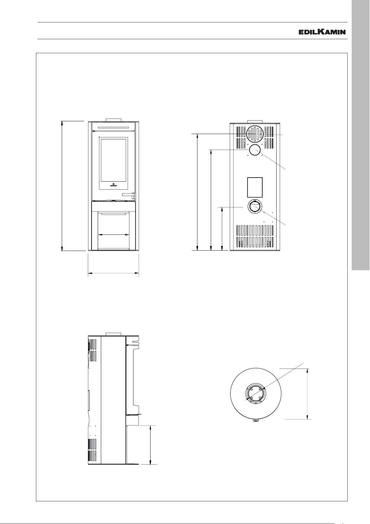
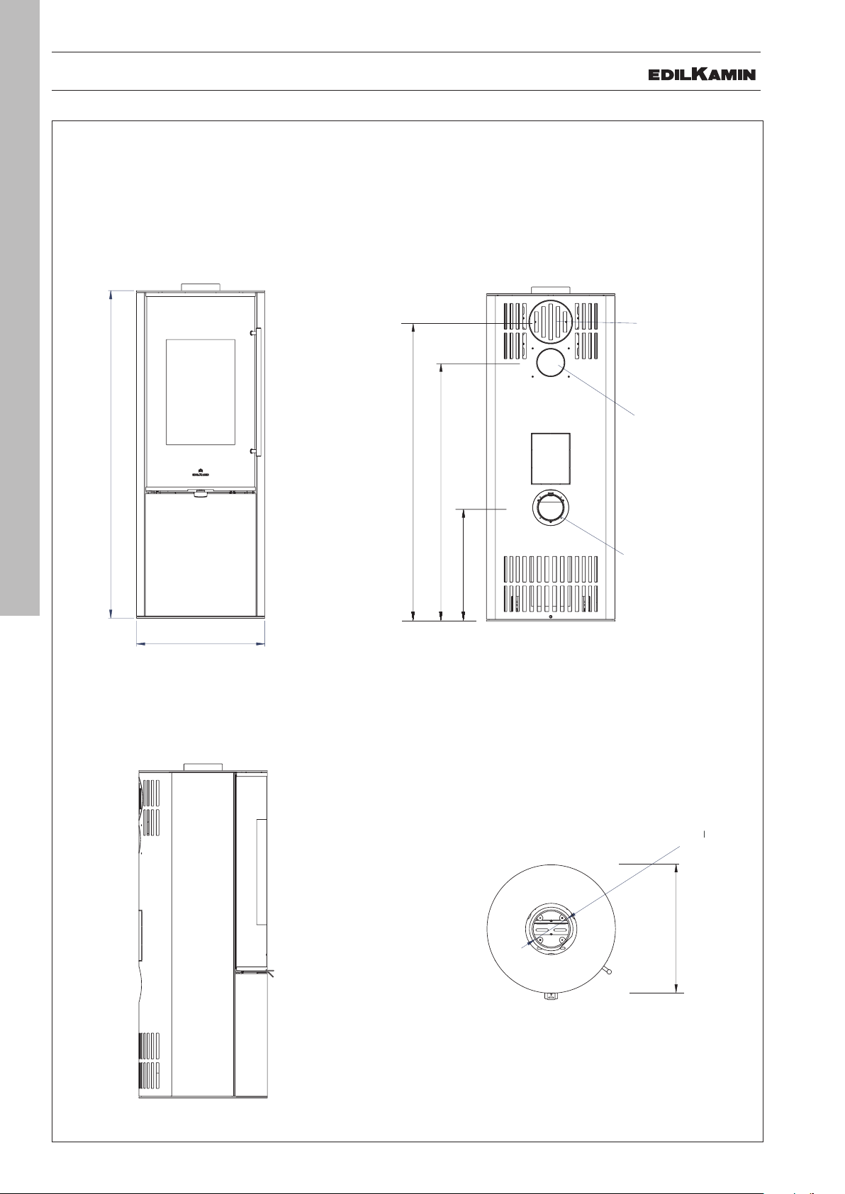
DIMENSIONS
38
38
Ø 15 cm
uscita fumi
Ø 8 cm aria
combustione
116,5
44
i
Ø 50
110
Ø 10 cm
uscita aria calda
31
44
38
131
pietra ollare
TALLY
- fireplace inner dimensions cm 29 (L) x 23 (P) x 38.5 (H)
Smoke outlet
Ø 15 cm
Ø 15 cm
uscita fumi
acciaio
steel
pietra ollare
soapstone
128
131
116,5
110
101
Ø 10 cm
Ø 10 cm
takes warm air for
uscita aria calda
ducting *
Combustion air
Ø 8 cm aria
Ø 10 cm
31
44
44
combustione
Ø 50
* use the specific kit (the
assembly instructions are
in the kit inside)
ENGLISH
5
Smoke outlet
Ø 15 cm
Ø 15 cm
uscita fum
Ø 50
38
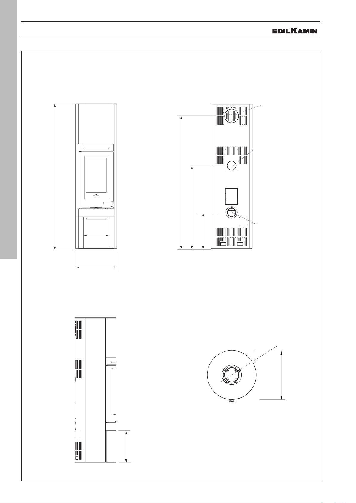
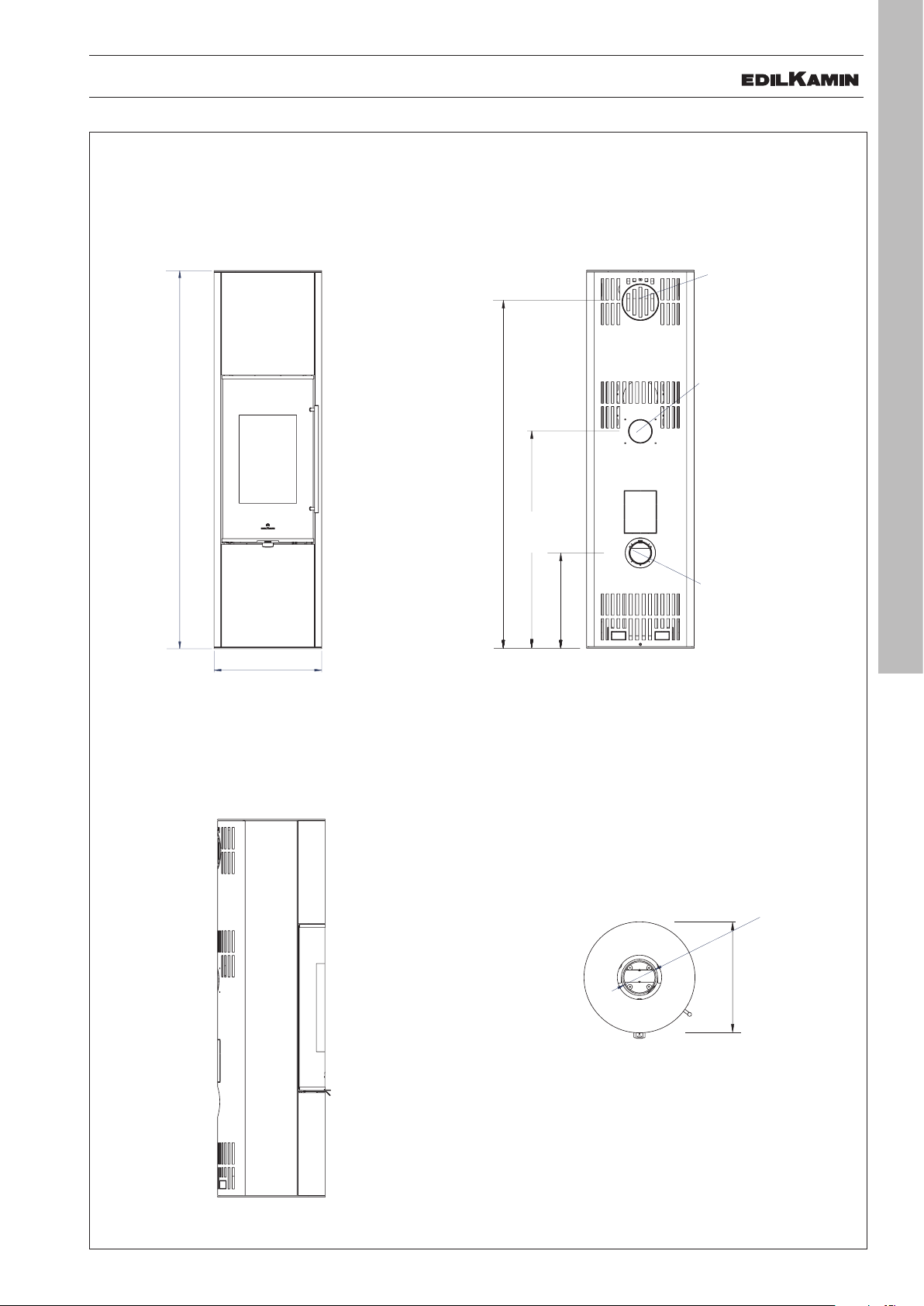
DIMENSIONS
161
44
110
Ø 15 cm
uscita fumi
Ø 10 cm aria
combustione
Ø 10 cm
uscita aria
calda
Ø 15 cm
uscita fumi
Ø 8 cm aria
combustione
116,5
44
i
Ø 50
110
Ø 10 cm
uscita aria calda
31
44
38
131
pietra ollare
161
44
Ø 15 cm
uscita fumi
Ø 50
110
Ø 50
Ø 15 cm
uscita fumi
Ø 10 cm aria
combustione
Ø 10 cm
uscita aria
calda
31
176
179
acciaio
pietra ollare
TALLY S
- fireplace inner dimensions cm 29 (L) x 23 (P) x 38.5 (H)
Smoke outlet
Ø 15 cm
uscita fumi
Ø 15 cm
Ø 10 cm
Ø 10 cm
uscita aria
takes warm air for
calda
steel
acciaio
pietra ollare
soapstone
161
176
179
ducting *
ENGLISH
6
31
Ø 50
110
101
Combustion air
Ø 10 cm aria
combustione
Ø 10 cm
44
* use the specific kit (the
assembly instructions are
in the kit inside)
Smoke outlet
Ø 15 cm
Ø 15 cm
uscita fum
Ø 50
38
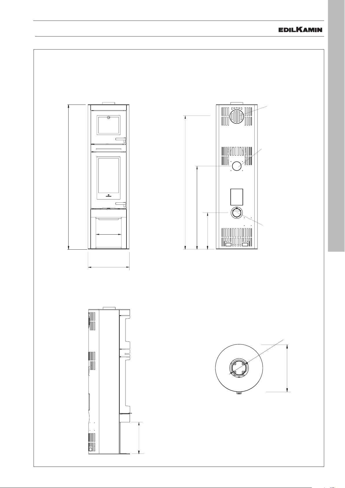
DIMENSIONS
161
44
Ø 15 cm
uscita fumi
Ø 10 cm aria
combustione
110
Ø 10 cm
uscita aria
calda
Ø 15 cm
uscita fumi
Ø 8 cm aria
combustione
116,5
44
i
Ø 50
110
Ø 10 cm
uscita aria calda
31
44
38
131
pietra ollare
161
44
Ø 15 cm
uscita fumi
Ø 10 cm aria
combustione
Ø 15 cm
uscita fumi
Ø 50
110
Ø 50
Ø 10 cm
uscita aria
calda
31
176
179
acciaio
pietra ollare
TALLY F
- fireplace inner dimensions cm 29 (L) x 23 (P) x 38.5 (H)
- food warmer dimensions cm 25 (L) x 31 (P) x 28 (H)
Not used
Ø 15 cm
uscita fumi
Ø 10 cm
Ø 10 cm
takes warm air for
uscita aria
calda
ducting *
161
110
44
Combustion air
Ø 10 cm aria
Ø 10 cm
combustione
* use the specific kit (the
assembly instructions are
in the kit inside)
Smoke outlet
Ø 15 cm
Ø 15 cm
uscita fum
ENGLISH
7
steel
acciaio
176
pietra ollare
soapstone
179
101
31
Ø 50
Ø 50
38
DIMENSIONS
116,5
128
Ø 15 cm
uscita fumi
Ø 10 cm aria
116,5
uscita fumi
Ø 50
110
Ø 10 cm
uscita aria
calda
131
acciaio
pietra ollare
TALLY UP
- fireplace inner dimensions cm 29 (L) x 23 (P) x 38.5 (H)
acciaio
pietra ollare
Smoke outlet
Ø 15 cm
uscita fumi
Ø 15 cm
Ø 10 cm
Ø 10 cm
uscita aria
takes warm air for
calda
ducting *
8
ENGLISH
128
131
110
101
Ø 10 cm aria
Combustion air
combustione
44
44
Ø 10 cm
Ø 50
* use the specific kit (the
assembly instructions are
in the kit inside)
Smoke outlet
Ø 15 cm
Ø 15 cm
Ø 50
DIMENSIONS
161
44
110
Ø 15 cm
uscita fumi
Ø 10 cm aria
combustione
Ø 10 cm
uscita aria
calda
161
44
uscita fumi
Ø 50
110
Ø 15 cm
uscita fumi
Ø 10 cm aria
combustione
Ø 10 cm
uscita aria
calda
176
179
acciaio
pietra ollare
161
44
110
Ø 15 cm
uscita fumi
Ø 10 cm aria
combustione
Ø 10 cm
uscita aria
calda
TALLY UP S
- fireplace inner dimensions cm 29 (L) x 23 (P) x 38.5 (H)
acciaio
pietra ollare
176
179
161
Smoke outlet
Ø 15 cm
uscita fumi
Ø 15 cm
Ø 10 cm
Ø 10 cm
uscita aria
takes warm air for
calda
ducting *
101
Ø 50
110
44
Combustion air
Ø 10 cm aria
Ø 10 cm
combustione
ENGLISH
9
* use the specific kit (the
assembly instructions are
in the kit inside)
Smoke outlet
Ø 15 cm
Ø 15 cm
Ø 50
TECHNICAL DATA
TECHNICAL CHARACTERISTICS according to EN 13240
The given data are indicative and taken during the certification stage at a notified Body under regulation conditions
Nominal power
Power output 6
Yield 85,6
Emissions CO 13% O
2
0,095
Fume temperature 160
Minimum draught 12
Fuel consumption 1,5
Heatable volume * 155
Smoke outlet pipe diameter (male) 150
Air intake pipe diameter (male) 100
Weight including packaging
Weight including packaging
(Tally - Tally/S - Tally/F) steel 150/200/200 soapstone 220/300/300
(Tally UP - Tally UP S) steel 150/200 soapstone 220/300
Refractory storage Kit (OPTIONAL) 40 kg
ENGLISH
kW
%
%
°C
Pa
kg/h
m
mm
mm
kg
kg
3
10
* The heating volume is calculated with the heat request of 33 Kcal/m³ hour
TECHNICAL DATA FOR THE DIMENSIONING OF THE FLUE
Nominal power
Power output 6 kW
Temperature of fumes on exit from the discharge pipe
192 °C
Minimum draught 5 Pa
Fume flow capacity 6 g/s
EDILKAMIN s.p.a. reserves the right to change the products at its discretion without notice.
OPTIONAL
OPTIONALS AVAILABLE FOR EACH MODEL
Optional Use Stove
Wood drawer storing wood Tally
Tally S
Tally F
Tally UP have wood drawer
Storage kit in refractory
material
Air Diffuser Kit ducting with hot air fan Tally
Connection Kit for the Air
Diffuser Kit ducting
Automatic ignition kit to light the wood automatically Tally
maintaining heat for as long as possible Tally S
Tally UP S
Tally UP
Tally S
Tally S UP
Tally F
to connect the ducting pipes to the rear of the
stove. In combination with the Air Diffuser Kit.
Tally
Tally UP
Tally S
Tally S UP
Tally F
Tally UP
Tally S
Tally S UP
Tally F
ENGLISH
11
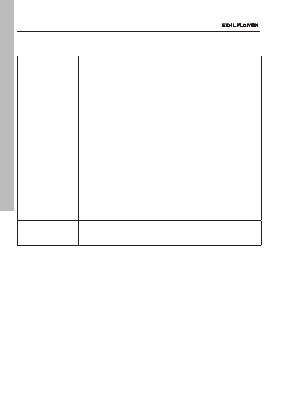
PACKAGING
PACKAGING
Model Version Figure No. of
packs
TALLY
TALLY UP
TALLY
TALLY UP
TALLY S
TALLY UP S
TALLY S
TALLY UP S
TALLY F STEEL: Fig. 5 4 • Structure (1)
ENGLISH
12
TALLY F POTSTONE Fig. 6 4 • Structure (1)
STEEL: Fig. 1 3 • Structure (1)
POTSTONE Fig. 2 3 • Structure (1)
STEEL: Fig. 3 4 • Structure (1)
POTSTONE Fig. 4 4 • Structure (1)
Components in packs
• Side panels, rear protection casing, top front panel
• Top (3)
• Rear protective casing (2)
• Series of stones (3)
• Side panels, rear protection casing, top front panel
• Top (3)
• S Kit, top part (4). The storage rings are optionals.
• Rear protective casing (2)
• Series of Stones (3)
• S Kit, top part (4). The storage rings are optionals.
• Side panels and rear protection casing and (only with
• Top (3)
• Food Warmer Kit
• Rear protective casing (2)
• Series of Stones (3)
• Food Warmer Kit (4)
and (only with Tally UP) bottom front panel for the
drawer (2)
and (only with Tally UP) bottom front panel for the
drawer (2)
TALLY UP) bottom front panel (2)
PACKAGING
TALLY e TALLY UP steel (fig. 1)
3
1
TALLY e TALLY UP stone (fig. 2)
TALLY S e TALLY UP S stone(fig. 4)
4
2
2
1
Prepared for
accumulation
OPTIONAL
3
TALLY F steel (fig. 5)
3
1
3
TALLY S e TALLY UP S steel (fig. 3)
4
3
2
2
2
ENGLISH
1
13
4
TALLY F stone(fig. 6)
2
1
Prepared for
accumulation
OPTIONAL
3
1
4
PACKAGING
PREPARATION AND UNPACKING
The materials composing the packaging are not toxic
or harmful, therefore no particular disposal processes
are required.
Storage, disposal and any recycling is the responsibility
of the end user in compliance with the laws in force on
the matter.
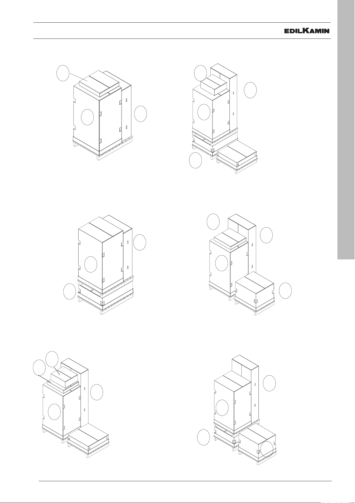
TO REMOVE THE PRODUCT FROM THE PALLET:
- remove the fastening screws on the pallet on both sides
of the stove
- remove the stove from the pallet and pay particular attention so the door and the glass are protected from mechanical knocks that could damage them.
ENGLISH
You are recommended to make each
movement in a vertical position with suitable
devices, paying attention to the safety
standards in force.
Do not overturn the packaging and be
cautious when assembling parts.
The packaging includes a useful inspection
hatch to check the status of the product.
On receipt, check and immediately notify
the retailer of any anomalies.
14
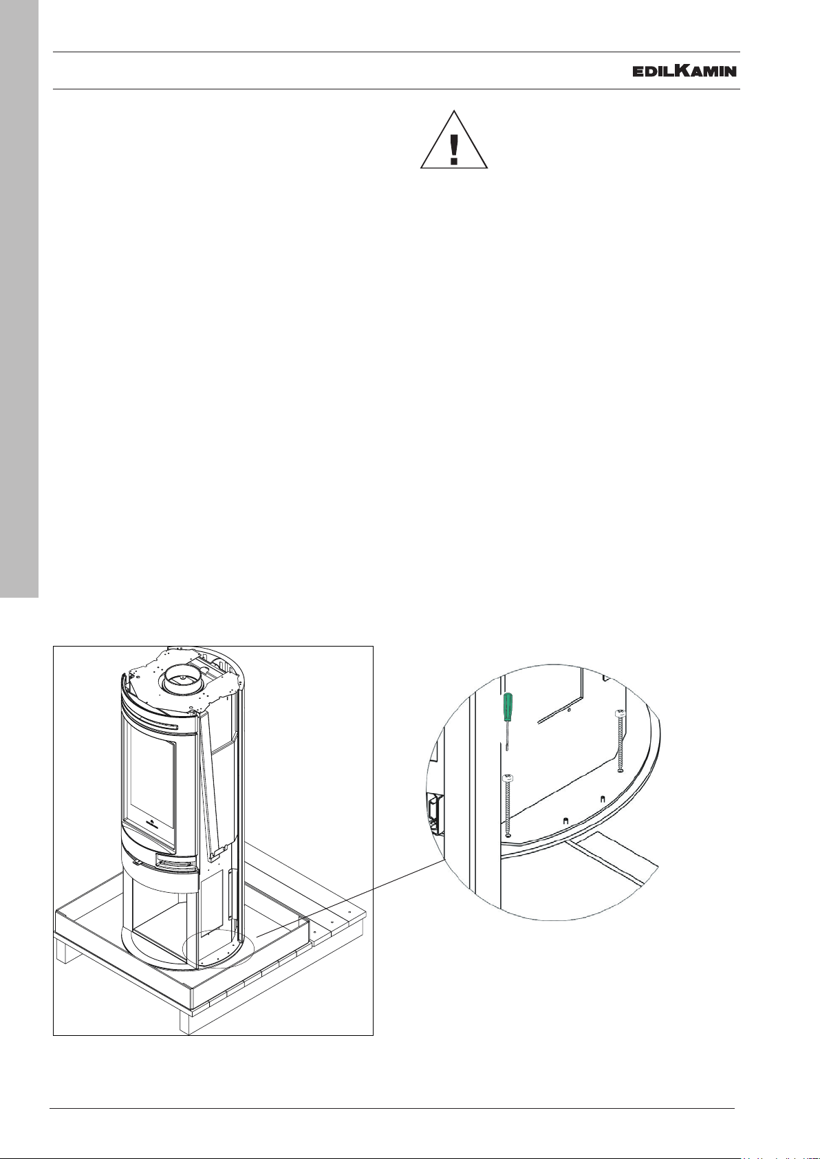
AIR DUCTING KIT
AIR DUCTING KIT (optional)
The stove is equipped for connecting the Air Diffuser
Kit, which allows warm air to be ducted to another
room using a fan.
To connect the Air Diffuser Kit (instructions with the kit),
you first need to mount the kit with the bracket (A) and
the flange (B) in order to fit the ducting pipe.
Fasten the bracket and the flange of the kit to the back
of the rear protective casing.
B
A
ENGLISH
15

OPTIONAL WOOD DRAWER
The pack for the optional drawer contains:
• 1 fitted drawer (A)
• 1 top cover (B);
• 4 self-tapping screws
WOODEN DRAWER KIT
B
A
FITTING THE OPTIONAL DRAWER
In order to fit the drawer, you need to prepare the
structure and then install the optional accessory
Preparing the structure:
ENGLISH
remove the wood box by unscrewing the three screws
(one per side and one at the back). The wood box is
16
replaced by the drawer.
Unscrew the CE marking plate from the
wood box and then fit it onto the drawer so
that the sign remains with the product
Once the wood box has been removed, the stove
appears as in the adjacent picture
1 per
side

FITTING THE OPTIONAL DRAWER
WOODEN DRAWER KIT
Preparing the optional drawer:
• slide the rails off
• insert the drawer into the prepared structure and
screw the rails onto the structure (2 screws per
side)
Optional drawer (A)
ENGLISH
17

CLADDING
FITTING THE TALLY AND TALLY UP STEEL CLADDING
The cladding is in two packs.
One contains:
• 1 rear protective casing (1)
• 2 side panels (2) and 1 front panel for the drawer, on the Tally UP model
• 1 hardware bag with:
- 10 self-tapping screws for the side panels and rear protective casing (and 4 additional screws for the UP version)
- 6 M 4x9 grub screws: 4 to be fixed to the sides of the base for the side panels; 2 for the top
- 2 M 5 grub screws (normally not used)
- 2 M 5 nuts and 1 dome bolt to make the door self-closing (see specific paragraph)
The other pack contains:
- 1 top (3)
- 1 top closure cap if the outlet is at the rear (4)
1
2
ENGLISH
18
SUMMARY OF OPERATIONS FOR FITTING THE CLADDING (description in the gures below)
4
3
1. Loosen the two screws on the bracket fixed to the
structure so as to be able to adjust the rear protective
casing;
2. insert the rear protective casing
1.
2.
1

CLADDING
3a. fasten it with 2 screws on the top part
3b. fasten it with 4 screws (2 per side) on the bottom
part, on the bracket referred to in point 1. Tighten the
screws that had previously been loosened under point
1.
4. screw the M 4x9 grub screws to the base (two per
side), onto which the side panels will be inserted
3a.
3b.
Grani
4.
5. fit the side panels (2) and fasten them (on all sides)
with 2 screws on the top part. Make sure that you insert
them at the bottom onto the previously-attached grub
screws
Insert the side panels with the profile facing
forwards.
ENGLISH
19
5.
2

CLADDING
6. prepare the top by screwing two M 4x9 grub screws
underneath.
7. then position the top, on top, centring the grub
screws in the holes on the U-shaped plate, which can
be adjusted if necessary with screw A.
6.
7.
vite A
screw A
3
U-shaped
plate
ENGLISH
20

CLADDING
ONLY FOR TALLY UP
In addition to what is mentioned in the previous pages
for the Steel Tally Base, the Tally UP has a wood drawer
with a steel front that needs fitting.
A
B
FITTING THE DRAWER CLADDING
• unscrew handle A from the drawer (figure below)
• insert the front panel in steel B
• screw on the front panel B using four screws (two
per side)
ENGLISH
21

CLADDING
FITTING THE TALLY AND TALLY UP STONE CLADDING
The cladding is in two packs.
The protective casing pack contains:
• 1 rear protective casing (1)
• 1 hardware bag with:
- 2 M 5 nuts and 1 dome bolt to make the door self-closing (see specific paragraph)
- 6 self-tapping screws to fasten the protective casing
The stone piece pack contains:
• 4 elements in stone: four are 48 cm long (2a) and two 78 cm long (2b), and, only for the UP version, another two
stone elements (38 cm long) for the drawer
• 1 top (3)
• 1 top closure cap if the outlet is at the rear (4)
• 6 lateral stone brackets (5)
• 2 stone block brackets (6)
• 1 hardware bag with:
- 16 screws in total: 12 for fastening the brackets (2 per bracket) and 4 for fastening the stone block brackets (2 per
bracket)
- 16 (spacer) pins to be screwed onto the stone pieces (4 for each stone piece)
- 2 pins to be placed under the top
- 8 M 6x8 screws for the UP version
ENGLISH
22
4
3
1
2a
2b

CLADDING
SUMMARY OF OPERATIONS FOR FITTING THE CLADDING (description in the gures below)
1. loosen the screws on the bracket fixed to the structure
so as to be able to adjust the protective casing;
2. insert the rear protective casing
3. fasten it with 2 screws on the top part and with 4
screws (2 per side) on the bottom part
3.
1.
2.
1
ENGLISH
23
4. Prepare the side elements in stone (2a and 2b),
by screwing the pins into the threaded inserts on the
stone.
Tighten or loosen the pins as required to
improve the alignment of the stones. In
case use the thickness too.
4.

CLADDING
5. fasten the metal brackets (5 - three per side) with
the self-tapping screws in line with the holes on the
structure.
6. starting at the bottom, insert the side panels onto
the metal brackets (5).
7. block the side panels using the Z-shaped bracket
(6).
Z-shaped
bracket (6)
5.
6.
7.
6
5
2b
5
2a
lateral stone
bracket (5)
ENGLISH
24
8. Position the top, on top, centring the locator pins in
the holes on the U-shaped plate.
fixed to the
structure

CLADDING
ONLY FOR TALLY UP IN STONE
In addition to what is mentioned in the previous pages
for the Tally Base, the Tally UP has a wood drawer
including a front with stone pieces that need to be
fitted and screwed on.
A
B
FITTING THE DRAWER CLADDING
• unscrew the handle (A) from the drawer. See figure
below;
• unscrew the bottom front wall (B);
• fasten the stones (C) by screwing them on from
the back
C
ENGLISH
25
B

FOOD WARMER KIT
FITTING THE TALLY F FOOD WARMER KIT
(to be done by the installation technician)
The food warmer kit pack contains:
• food warmer system
• internal elements of the food warmer (fixed tray to be fitted onto the stove after installation and the removable
tray)
• hardware:
- 10 self-tapping screws;
- 4 thread-forming screws;
- gasket
To remove it from the pallet open the
door and undo the screws (V) used to fix the food
warmer kit to the pallet.
V
x n° 4
ENGLISH
26
SUMMARY OF OPERATIONS FOR FITTING THE FOOD WARMER KIT (description in the gures
below)
1. remove the U-shaped plate and the combustion gas
collar.
1.
U-shaped plate
combustion
gas collar

FOOD WARMER KIT
2. dismantle the top front panel of the structure, by
unscrewing the side screws
3. also with the food warmer kit on the floor, loosen
the screws of the front plate and the two rear brackets
so as to allow the four central screws to be positioned
correctly later
2.
3.
If presente,check the condition of the
adhesive gasket under the food warmer.
If required, apply a new one. IF NOT
PRESENT APPLY A NEW ONE
4. place the food warmer kit on the structure. Open the
door, tighten the four internal thread-forming screws
(without over-tightening) to block it with the structure,
the two front self-tapping screws (Figure 4a) and the
screws on the rear brackets. Then tighten the screws
further, starting with the rear ones and re-tighten the
previously-loosened screws.
4a.
ENGLISH
27
4.
internal threadforming screws x 4
bracket
screws,
one per side
5. re-position the U-shaped plate and the combustion
gas collar on top of the food warmer kit and re-position
the top front panel of the structure, removed in points 1
and 2, and screw the fixed tray inside the food warmer.

KIT S
ASSEMBLING THE TALLY S (STORAGE) S KIT (to be done by the installation technician)
THE RINGS IN REFRACTORY MATERIAL (3) ARE OPTIONAL
The S Kit pack contains:
• 3 containment walls of the S Kit (1)
• 2 L-shaped brackets for fixing the protective casing (2)
• 18 self-tapping screws to screw the containment walls of the S Kit
2
ENGLISH
28
1
(3) Rings
OPTIONAL

KIT S
SUMMARY OF OPERATIONS FOR ASSEMBLING THE STORAGE KIT (description in the gures
below)
1. remove the U-shaped plate from the structure
2. join together the side containment walls of the S Kit
(1) and screw them onto the structure.
Fix the front section last of all (mounting the cladding),
because the potstone front piece is screwed onto
this.
3. install the two L-shaped brackets (2) for fixing the
rear protective casing.
1.
U-shaped plate
2.
3.
2
4.
1
*
*
3
1
ENGLISH
29
4. IF PURCHASED AS AN OPTIONAL, fit the stone
discs of the storage unit (3) inserting them one on
top of the other
In case of exit rear, dontt use the two
upper discs*
5. re-position the previously-removed U-shaped plate
onto the storage kit.
6. then fit the rear protective casing and proceed with
fitting the cladding in steel or potstone (at which time
the front panel of the S Kit will also be fitted)
5.
6.
1
2

CLADDING
FITTING THE TALLY F, TALLY S AND TALLY UP S STEEL CLADDING
The cladding is in two packs.
One contains:
• 1 rear protective casing (1)
• 2 side panels (2)
• 1 top front panel (3) and, for the Tally UP S model, the front panel for the drawer
• 1 bag of hardware with:
- 22 self-tapping screws in total: for the side panels (4 = 2 per side), for the rear protective casing (10 = 2 for the top
and 4 per side on the brackets), 4 for the top front panel and 4 for the U-shaped plate and 4 additional screws for the
UP version;
- 6 M 4x9 grub screws: 4 to be fixed to the sides of the base for the side panels; 2 for the top
- 2 M 5 grub screws (normally not used)
- 2 M 5 nuts and 1 dome bolt to make the door self-closing (see specific paragraph)
The other pack contains:
- 1 top (4)
- 1 closure cap (5) if the outlet is at the rear
ENGLISH
30
1
5
3
2
4

CLADDING
SUMMARY OF OPERATIONS FOR FITTING THE CLADDING (description in the gures below)
1. Loosen the screws on the bracket fixed to the
structure so as to be able to adjust the protective
casing;
2. insert the rear protective casing
3a. fasten it with 2 screws on the top part
1.
3a.
2.
1
3b. fasten it with 4 screws (2 per side) on the top part
on the bracket fitted with the S Kit
3c. fasten it with 4 screws (2 per side) on the bottom
part of the bracket referred to in point 1.
4. screw the M 4x9 grub screws to the base (two per
side), onto which the side panels will be inserted
3b.
3c.
4.
ENGLISH
31
grub screws

CLADDING
5. insert the front panel (3) from above and screw it on
6. fit the side panels (2) and fasten them with 2 screws
on the top part. Make sure that you insert them at the
bottom onto the previously-attached grub screws
5.
6.
top front panel
food warmer version
3
top front panel storage unit version
3
ENGLISH
32
7. prepare with the grub screws and position the top as
with the base version
Then position the top, on top, centring the grub
8.
screws in the holes on the U-shaped plate. If required,
any alignments can be made with the screw fastened to
the U-shaped plate.
2
7.
Grub screws

CLADDING
ONLY FOR TALLY UP
In addition to what is mentioned in the previous pages
for the Steel Tally Base, the Tally UP has a wood drawer
with a steel front that needs fitting.
A
B
FITTING THE DRAWER CLADDING
• unscrew handle A from the drawer (figure below)
• insert the front panel in steel B
• screw on the front panel B using four screws (two
per side)
ENGLISH
33

CLADDING
FITTING THE TALLY F and S or TALLY UP S STONE CLADDING
The cladding is in two packs:
The protective casing pack contains:
- 1 rear protective casing (1)
1 hardware bag with:
- 2 M 5 nuts and 1 dome bolt to make the door self-closing (see specific paragraph)
- 10 self-tapping screws to fasten the protective casing
The stone piece pack contains:
• 6 lateral elements in stone: four are 48 cm long (2a) and two 78 cm long (2b), and, only for the UP version, an-
other two stone elements (38 cm long) for the drawer
• 2 elements in stone for the front piece (2a)
• 1 top (3)
• 1 top closure cap (4) if the outlet is at the rear
• - 10 brackets for the lateral stone (5)
• 2 Z-shaped stone block brackets (6)
1 hardware bag with:
- 24 screws: 20 for fastening the brackets (2 per bracket) and 4 for fastening the stone block brackets (2 per bracket)
- 24 (spacer) pins to be screwed onto the stone pieces (4 for each stone piece)
- 2 pins to be placed under the top
- 8/4 M 6x8 screws (depending on if it is an S or F model) for the stones of the top front panel
- 8 M 6x8 screws for the UP version
ENGLISH
34
1
4
3
2a
2b

CLADDING
SUMMARY OF OPERATIONS FOR FITTING THE CLADDING (description in the gures below)
1. Loosen the screws on the bracket fixed to the
structure so as to be able to adjust the protective
casing;
2. insert the rear protective casing
1.
2.
1
3a. fasten it with 2 screws on the top part
3b. fasten it with 4 screws (2 per side) on the top part
on the bracket fitted with the S Kit
3c. fasten it with 4 screws (2 per side) on the bottom
part of the bracket referred to in point 1.
3a.
3b.
3c.
ENGLISH
35
4. Prepare the side elements in stone (2a and 2b),
by screwing the pins into the threaded inserts on the
stone.
Tighten or loosen the pins as required to
improve the alignment of the stones. n
case use the thickness too.
4.

CLADDING
5. fit the two parts of the top front panel in stone (the
large one for the S version and small one for the F
version) by screwing the stones to the front wall of the
S Kit
After fitting, it may be necessary to reposition some stones in order to improve
overall alignment.
6. fasten the metal brackets (5 - five per side) with
the self-tapping screws in line with the holes on the
structure.
7. starting at the bottom, insert the side panels onto
the metal brackets (5).
8. block the side panels using the Z-shaped bracket
(6).
5.
6.
7.
8.
(small) top front panel
potstone version food
warmer F
ENGLISH
36
Z-shaped
bracket (6)
lateral stone
bracket (5)
fixed to the
structure
walls of the S Kit
front panel in stone
6
5
5
5
5
5
9. Position the top, on top, centring the locator pins in
the holes on the U-shaped plate.

CLADDING
ONLY FOR TALLY UP IN POTSTONE
In addition to what is mentioned in the previous pages
for the Tally Base, the Tally UP has a wood drawer
including a front with stone pieces that need to be
fitted and screwed on.
A
B
FITTING THE DRAWER CLADDING
• unscrew the handle (A) from the drawer. See figure
below;
• unscrew the bottom front wall (B);
• fasten the stones (C) by screwing them on from
the back
C
ENGLISH
37
B

INSTALLATION
1
2
4
1
SMOKE OUTLET
The stove is prepared for connection of the smoke
outlet tube from the top and back.
The stove is delivered configured for the smoke outlet
pipe from the top.
For smoke outlet from the rear:
- remove the pre-cut diaphragm to the rear (1)
- unscrew the two screws from the smoke coupling
collar on the top of the stove (2) and the two screws
fastening the plug on the rear of the stove (3)
- invert the two parts (smoke coupling collar 2 and plug
3) and screw them back in, paying attention to the seal
- inside the stove packaging there is a metal cover
supplied which should be used to close the smoke
outlet hole on the top (4).
POSITIONING ON THE FLOOR
The stove is not fitted with feet.
You can decide whether to add felt pads to ensure
easier movement of the stove.
Place the stove on a perfectly-flat surface.
ENGLISH
38
In case of exit rear, dontt use the two
upper discs*
4
3
1

INSTALLATION
INTRODUCTION ON INSTALLATION
Remember that:
• the stove must be installed by qualified staff who
can issue a Declaration of Conformity
• all the local and national laws and the European
Standards must be met for installation and use of
the product.
• In the event of installation in apartment blocks, ask
the administrator’s opinion beforehand.
The general instructions are provided below, taking
the Italian standard UNI 10683 as an example and
guideline.
Checking the suitability of the installation
premises
• The volume of the room must be over 15 m
3
• Installation is not permitted in bedrooms,
bathrooms or premises with other products that
take in air for combustion of the same premises
or in premises with an explosive atmosphere. Any
extractor fans, if working in the same environment
or space in which the product is installed, can
cause draft problems.
• In Italy, check compatibility pursuant to UNI 10683
and UNI 7129 in the presence of gas products.
• The floor must be able to support the weight of the
stove and the accessories.
Protection from heat and safe distances
All the surfaces of the building adjacent to the stove
must be protected against heating.The insulation
measurements to implement depend on the type of
surface present.
Distance from flammable materials must be:
- 25 cm from the sides ;
- 20 cm from the back
CHIMNEY SYSTEM
(Smoke channel, chimney ue and chimney
stack)
This chapter is drafted according to the European
Standards EN 13384, EN 1443, EN 1856, EN 1457. The
installation technicians must take into consideration
these and any other local standards. The manual
should in no way be considered a replacement for the
laws in force.
The stove must be connected to a suitable smoke
discharge that guarantees completely safe evacuation
of the smoke produced by combustion.
Before positioning the stove, you need to check the
chimney flue is suitable.
SMOKE CHANNEL, CHIMNEY FLUE
The smoke channel (pipe that connects the smoke
outlet of the fireplace with the chimney flue inlet) and the
chimney flue must, along with other legal provisions:
• receive the discharge for a single product (multiple
product discharges are not permitted together)
• have a mainly vertical development
• no section should have a reserve slope
• have an inner section preferably circular and
however with a ratio between sides lower than 1.5
• complete the roof with the appropriate chimney
stack: direct discharge is forbidden on walls or
towards closed spaces, even if outdoors
• be created with materials with a fire reaction class
A1 pursuant to UNI EN 13501 or similar national
standard
• be appropriately certified, with an appropriate
fireplace plate, if metal
• keep the initial section or change it only immediately
above the stove output and not along the chimney
stack
ENGLISH
39
In the event of installation on a floor with inflammable
material and/or combustible material or with insufficient
capacity, you are advised to position the stove on a
steel or glass plate to distribute the load.Ask the retailer
about the optionals.

INSTALLATION
THE SMOKE CHANNEL
•ifinmetalmusthavea CEmarking(EN1856-2)or
similar national law;
•cannotbeinflexiblemetalmaterial
•
to check the flow, a shutter is advised for draft over
25 Pa
THE CHIMNEY FLUE:
• must have a draft capable of creating negative
pressure ideally around 12 Pa. Lower drafts can
cause leaking smoke if the door is open; higher
values tend to generate fast combustion by
reducing the yield
• must be correctly sized to meet smoke evacuation
(EN 13384-1)
• must preferably be insulated, in steel with a circular
inner section. If rectangular, the inner edges must
have a radius under 20 mm and a ratio between
between the inner dimensions <1.5
• normally have a minimum height of 3.5-4 metres
• maintain a constant section
• be waterproof and thermally insulated to guarantee
draft.
• preferably create a collection chamber for
unburned fuel and any condensate
ENGLISH
• be at least category T400, with an adequate
40
resistance to soot fireIf pre-existing, it must be
cleaned to avoid risk of fire.
EXTERNAL AIR INTAKE
To re-integrate burnt oxygen during stove functioning,
you need to have an installation premises suitable for
the external air intake.The intake must preferably be
installed at floor level and must have a passing surface
of at least 200 cm² (Ø 16).Alternatively, you can take
the air for combustion directly from outside.Connect a
Ø 10 cm tube directly on the back of the stove (1), by
applying a protection grid which must not reduce the
passing useful section.You are advised not to exceed
3 metres in length based on the chimney flue draft.
THE CHIMNEY STACK
• must be wind-proof
• have an internal section equivalent to that of the
chimney flue and passage section outlet equal to
at least double the inner passage of the chimney
flue
• for paired chimney flues (which should be at least
2 m apart) the chimney stack of the chimney flue
receiving the product discharge with solid fuel or
that of the highest floor must be at least 50 cm
taller
• must go beyond the reflux zone
• must enable chimney maintenance
1

ISTRUCTIONS FOR USE
FUEL
The stove was designed to burn wooden logs or
sawdust briquettes.
Use dry wood logs (max. humidity 20%)Use logs with
a maximum length around 33 cm vertically and 25 cm
horizontally and a maximum diameter of 20-30 cm The
use of damp wood would cause the product and the
flue to get dirty, the risk of smoke and a lower yield
than that declared.Each type of wood has different
characteristics that also influence combustion yield.
The data outlined on this manual are with wood used
during certification.
In general wood can have a heat of combustion up to
4.5 kWh/kg while cut fresh it has heat of combustion
around 2 kWh/kg
In general, beech or elm is recommended, or however
class A1 wood according to UNI EN ISO 17225-5
Attention to prolonged use of wood with aromatic oils
(e.g. eucalyptus). Cast iron parts can deteriorate
Use the recommended quantities of wood:
Overloading causes overheating, resulting in damage:
• possible deformation of the inner parts;
• possible irreversible changes to the colour of the
paint on the metal parts
for which Edilkamin or the retailer cannot be held liable.
AIR ADJUSTMENT
Move the air adjustment lever forward or back to allow
more or less combustion air in the combustion chamber.
- “Brazier Maintenance” position (Fig. 1)
Air valve command withdrawn.
This position is used to extend combustion (for example at
night, or when you are not at home) so the product goes to
the minimum, saving fuel and maintaining the flame.
FIG. 1
- Intermediate position (Fig. 2)
Command in intermediate position.
This position allows combustion completion.
ENGLISH
To respect the environment and safety, do NOT burn,
among other things: plastic, varnished wood, coal and
bark waste.
Do not use the stove as an incinerator.
Use of these fuels also nullifies the guarantee.
41
FIG. 2
- “Switch on”/max power position (Fig. 3)
Air valve command totally extracted.It has the purpose of
bringing a large quantity of air in the fireplace to enable
quick and efficient lighting of the fire. Useful to switch on a
cold stove and give maximum power in the fireplace.
FIG. 3

ISTRUCTIONS FOR USE
First switch on phases
• Ensure you have read and understood the content
of this manual
• Remove all the inflammable parts from the product
(manuals, labels, etc.). In particular remove any
labels from the glass. If they melt, they would
irreversibly damage the glass.
For initial switch on of the fireplace, always use the
smallest logs. Use larger wooden logs to raise the fire.
Always locate the wood deep in the fireplace, almost in
contact with the rear wall, so that even if they slide they
won’t come in contact with the glass.
There may be a slight smell of paint the first few times it
is ignited, however, this will disappear quickly.
Lighting a cold replace
1. Check the existing ash bed is not too high. If the
ash bed is too high, there is a danger of opening the
door of the fireplace to add wood and possible brazier
fragments fall out of the fireplace.
2. Position the adjustment lever of the valve in the “total
opening” position. The air for combustion will flow
intensely to the wood in the fireplace, to quickly reach
ENGLISH
good combustion.
42
3. place the wood in the fireplace without excessively
squashing it in. Position a firelighter between the wood
logs and light. Never user materials such as petrol,
alcohol and similar to switch on.
4. At this point, close the door and monitor it for a few
minutes. If the fire should extinguish, slowly open the
door, re-position another firelighter between the logs
and light again.
Lighting a hot replace
When should wood be added? When the fuel is
almost completely consumed to embers. With the
glove supplied, slowly open (to avoid formation of
vortexes that can cause smoke to exit) the door. Add
the desired wood to the fireplace, locating it on the
existing embers (within the quality limits indicated in
the technical table).
Stove functioning changes with the chimney flue draft
and adjustment of the air valve in combustion.
Functioning with initial low draft
To extract air for combustion and discharge the
smoke, the fireplace needs a draft to be exerted on the
chimney flue.
If the draft is weak, initially light a “starter” fire using
small sized lighting material.
Once the correct draft is restored, you can add the fuel.
As with all the products, the wood stove heats and
cools during the various phases. This would lead to
normal dilation. Such dilation can cause slight settling
noise, which is not a reason for dispute.
The hot air reaches the premises with natural motion
(natural convection) without the help of a fan.The
retailer also offers an Air Diffuser kit with fans to
distribute the hot air in the premises.
NOTE FOR UK
Refuelling on to a low fire bed
If there is insufficient burning material in the firebed to
light a new fuel charge, excessive smoke emission can
occur. Refuelling must be carried out onto a sufficient
quantity of glowing embers and ash that the new fuel
charge will ignite in a reasonable period. If there are
too few embers in the fire bed, add suitable kindling to
prevent excessive smoke
Fuel overloading
The maximum amount of fuel specified in this manual
should not be exceeded, overloading can cause
excess smoke.

ISTRUCTIONS FOR USE
Tally is equipped with a piston to enable door closure
return, if opened up to little under 90 °.
Opening over the 90 °, the door will not close.
The Tally stove can be made fully self-closing by
applying a screw in the threaded hole in the figure
below.
SPECIAL FEATURES OF TALLY S AND
TALLY F
The food warmer was designed not as an oven for
baking but simply to heat food.
Ordinary maintenance is recommended with tray
removal.
Tally S accumulation was designed to maintain heat
and diffuse it even when the stove is off.
Accumulation in refractory material absorbs the heat
produced by the stove and gradually releases it in the
premises.
This means you can keep the premises warm for hours
without loading it.
The heat released naturally depends on the previous
loads and the overall installation and use situation.
ENGLISH
43

MAINTENANCE
ATTENTION!
All the cleaning operations of all the parts
should be carried out with the stove completely cooled.
Removing ash
The ash pan is located under the fireplace.It must
absolutely be emptied before the ash reaches the hip.
It should be removed when the stove is cold, for
example each morning before switch on.
Cleaning the glass
You can use specific products to clean the glass (see
our Glasskamin pricelist).
Do not spray the product on painted parts or the seals of the door. An alternative to the product is a rag
soaked in a bit of white ash and a piece of newspaper. Attention, ensure there are no abrasive elements
in the ash that could scratch the glass.
Ceramic glass installed on the products can
resist heat up to approx. 750°C and is tested
and controlled before and after assembly to
check for the presence of cracks, bubbles
ENGLISH
44
and blowing.
The glass, despite its high resistance to temperature, is however a fragile element and
therefore you are advised to move the door
cautiously without banging or forcing it.
Glass, since it is not flexible, can break.
Cleaning the external parts
The covering must be clean without using aggressive
detergents. Do not wet with cold water when the
covering is hot because the thermal shock could
cause damage.
Cleaning the chimney ue
This should be carried out before the use season and
each time you note a layer of soot and tar has formed
inside, a substance that is easily flammable.
Scale, in the presence of high temperatures and
sparks, can catch fire with serious consequences
both for the chimney flue and for the home. You are
therefore advised to clean at least once a year.

IN THE EVENT OF PROBLEMS
IN THE EVENT OF PROBLEMS
1) In case of smoke leaking from the
replace hearth, check if:
Installation is correct (smoke channel, chimney flue,
stack, air intake). The wood used is dry.the door was
opened too quickly
2) In the event of uncontrolled combustion,
check if:
The seals of the fireplace are intact:
The door of the fireplace is closed properly.
3) If the glass gets dirty quickly, check if:
The wood used is dry.
However, consider that after a few hours of work, it is
normal for a light layer of soot to form on the glass.
4) If the chimney flue catches fire or you need to
suddenly extinguish the fire lighting in the fireplace:
• if possible, in safe conditions, remove the ash and
brazier using tools and only touch metal containers
with fireproof gloves.
• in the event of a fire, ask the authorities for help
NOTES ON REFRACTORY MATERIAL
The inner refractory material was designed to resist
normal use.
Its cleaning is ensured by good combustion.The main
damage to refractory material comes from:
• accidental knocks
• use of firelighters which are not ecologicalloading
• wood beyond the recommended amount (1.5
kg/h)
• use of fuel other than that recommended
Edilkamin or the retailer cannot be held liable for
damage caused as described above
DISPOSAL
At the end of its service life, dispose of the product as
required by regulations.
5) In case of odours, check if:
If first switch on: in this case a paint smell is normal.
If the product is dirty or dusty
If you cannot solve the problem, contact
the retailer or, in countries where present,
the authorised Technical Support Centre.
The guarantee is only valid if the product
defect is proven.
ENGLISH
45


*941291-GB*
www.edilkamin.com
cod. 941291-GB 10.16/L
 Loading...