

EdilKamin PELLINSERT 54 Installation, Use And Maintenance Manual
PELLINSERT 54
I Installazione, uso e manutenzione pag. 2
UK Installation, use and maintenance pag. 18
F Installation, usage et maintenance pag. 34
E Instalación, uso y mantenimiento pag. 50
D Installations-, Betriebs- und Wartungsanleitung pag. 66
NL Installatie, gebruik en onderhoud pag. 82

Gentile Sig.ra/Egregio Signore
La ringraziamo per avere scelto Pellinsert 54
Prima di utilizzare l’inserto, Le chiediamo di leggere attentamente questa scheda, al fine di poterne sfruttare al meglio e in totale sicurezza tutte le caratteristiche.
Per ulteriori chiarimenti o necessità contatti il suo Rivenditore di zona o visiti il sito intenet www.edilkamin.com alla voce CENTRI
ASSISTENZA TECNICA.
Le ricordiamo che la 1° accensione DEVE essere effettuata da CAT (centro di assistenza tecnica abilitato EDILKAMIN) che verifichi
l’installazione e effetui la necessaria taratura (norma UNI 10683 rev. 2005) e compili la garanzia, attivandola.
Installazioni scorrette, manutenzioni non correttamente effettuate, uso improprio del prodotto, sollevano l’azienda produttrice da ogni
eventuale danno derivante dall’uso.
INFORMAZIONI PER LA SICUREZZA
• PELLINSERT 54 è progettato per scaldare il locale nel quale si trova per irraggiamento e per movimento di aria.
L’aria calda esce dal frontale dell’inserto in modo indiretto evitando quindi un impatto fastidioso sull’utilizzatore.
• Gli unici rischi derivabili dall'impiego dell’inserto sono legati a mancato rispetto delle norme d'installazione o a un
diretto contatto con parti elettriche in tensione (interne) o a un contatto con fuoco e parti calde (vetro, tubi, uscita aria
calda) o all'introduzione di sostanze estranee nel focolare.
• Usare come combustibile solo pellet di legno di diametro 6 mm.
• Nel caso di mancato funzionamento, l’inserto è dotato di dispositivi di sicurezza che ne garantiscono lo spegnimento;
spegnimento che deve avvenire in modo automatico senza forzature da parte dell’utilizzatore.
• Per un regolare funzionamento l’inserto deve essere installato rispettando quanto indicato sulla presente scheda tecnica.
• Durante il funzionamento non deve essere aperta la porta: la combustione è infatti gestita automaticamente e non
necessita di alcun intervento.
• Come combustibile utilizzare solo pellet: in nessun caso devono essere introdotte nel focolare o nel serbatoio sostanze
estranee.
• Per la pulizia dei percorsi fumo non devono essere utilizzati prodotti infiammabili.
• Per la pulizia, le parti del focolare e del serbatoio devono essere solo aspirate con aspirapolvere.
• Il vetro può essere pulito a FREDDO con apposito prodotto (es. GlassKamin) e un panno. Non pulire a caldo.
• Assicurarsi che l’inserto venga posato e acceso da CAT (centro assistenza tecnica) abilitato EDILKAMIN,
autorizzato a compilare la garanzia, solo a queste condizioni la garanzia si attiverà.
• Durante il funzionamento dell’inserto, i tubi di scarico e la porta raggiungono alte temperature (istuire i bambini).
• Non depositare oggetti non resistenti al calore nelle immediate vicinanze dell’inserto, vedere distanze minime a pag. 9
• Non usare MAI combustibili liquidi per accendere l’inserto o ravvivare la brace.
• Non occludere le aperture di aerazione nel locale di installazione, né gli ingressi di aria all’inserto stesso.
• Non bagnare l’inserto, non avvicinarsi alle parti elettriche con le mani bagnate.
• Non inserire riduzioni sul tubo di scarico fumi
• L’inserto deve essere installato in locali adeguati per la prevenzione incendio e dotati di tutti i servizi (alimentazione
e scarichi) che l’apparecchio richiede per un corretto e sicuro funzionamento.
In caso di fallita accensione, prima di ripetere l’accensione svuotare il crogiolo.
2
ITALIANO
La scrivente EDILKAMIN S.p.a. con sede legale in Via Vincenzo Monti 47 - 20123 Milano - Cod. Fiscale P.IVA 00192220192
Dichiara sotto la propria responsabilità che:
L’ inserto a pellet sotto riportata è conforme al Regolamento UE 305/2011 (CPR) ed alla Norma Europea armonizzata
EN 14785:2006
INSERTO A PELLET, a marchio commerciale EDILKAMIN, denominata PELLINSERT 54
N° di SERIE: Rif. Targhetta dati Dichiarazione di prestazione (DoP - EK 038): Rif. Targhetta dati
Altresì dichiara che:
l’inserto a pelle di legno PELLINSERT 54 rispetta i requisiti delle direttive europee:
2006/95/CE - Direttiva Bassa Tensione
2004/108/CE - Direttiva Compatibilità Elettromagnetica
EDILKAMIN S.p.a. declina ogni responsabilità di malfunzionamento dell’ apparecchiatura in caso di sostituzione, montaggio e/o
modifi che effettuate non da personale EDILKAMIN senza autorizzazione della scrivente.
PRINCIPIO DI FUNZIONAMENTO
PELLINSERT 54 è un inserto che utilizza come combustibile il pellet, la cui combustione è gestita elettronicamente.
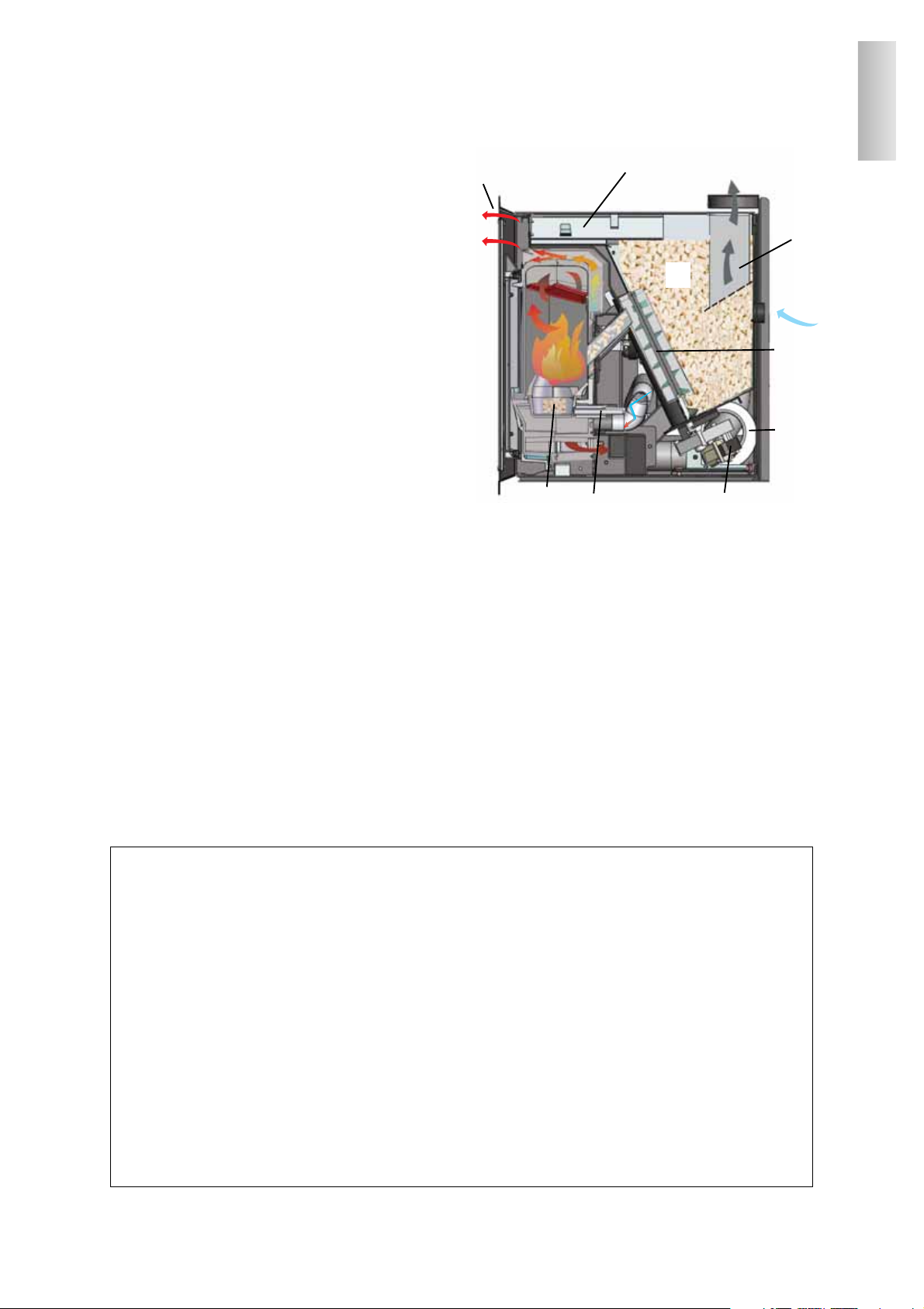
Il combustibile (pellet) viene prelevato dal serbatoio di stoccaggio (A) e, tramite una coclea (B) attivata da motoriduttore (C), viene trasportato nel crogiolo di combustione (D).
L'accensione del pellet avviene tramite aria calda prodotta
da una resistenza elettrica (E) e aspirata nel crogiolo tramite un ventilatore centrifugo.
I fumi prodotti dalla combustione, vengono estratti dal
focolare tramite lo stesso ventilatore centrifugo, ed espulsi
dal bocchettone (F) ubicato nella zona alta dell’inserto.
Tramite i ventilatori (G) viene fatta transitare aria nell’intercapedine sul retro del focolare, dove si riscalda per poi
uscire in ambiente frontalmente dalle feritoie (H).
Il serbatoio del combustibile (A) è ubicato nella parte
posteriore dell’inserto.
Il riempimento del serbatoio avviene attraverso un cassetto
scorrevole (I), posto nella parte frontale sopra il focolare.
Il focolare è realizzato con una struttura interna completamente in ghisa, frontalmente chiusa da due antine sovrapposte.
- un’antina esterna in vetro ceramico
(per l’apertura utilizzare l’apposito guanto termico).
- un’antina interna a contatto con il fuoco
(per l’apertura utilizzare l’apposita mano fredda in dota-
zione).
La quantità di combustibile, l’estrazione fumi e alimentazione aria comburente, sono regolate tramite scheda elettronica al fine di ottenere una combustione ad alto rendimento.
Tutte le operazioni per la gestione del funzionamento possono essere gestite tramite radiocomando in dotazione.
In caso di rottura o smarrimento del radiocomando, l’accensione e spegnimento potrà avvenire tramite un pulsante
di emergenza posto all’interno dell’inserto (vedi pag.13).
NOTA sul combustibile.
PELLINSERT 54 è progettata e programmata per bruciare pellet di legno di diametro 6 mm circa. Il pellet è un combustibile che si presenta in forma di piccoli cilindri del diametro di 6 mm circa, ottenuti pressando segatura, senza uso di collanti o altri materiali estranei. E’ commercializzato in sacchetti da 15 Kg.
Per NON compromettere il funzionamento dell’inserto è indispensabile NON bruciarvi altro. L'impiego di altri materiali
(legna compresa), rilevabile da analisi di laboratorio, implica la decadenza della garanzia.
EdilKamin ha progettato, testato e programmato i propri prodotti perché garantiscano le migliori prestazioni con pellet delle
seguenti caratteristiche:
- diametro : 6 millimetri
- lunghezza massima : 40 mm
- umidità massima : 8 %
- resa calorica : 4300 kcal/kg almeno
L'uso di pellet con diverse caratteristiche implica la necessità di una specifica taratura dell’inserto, analoga a quella che fa
il CAT (centro assistenza tecnica) in 1° accensione.
L'uso di pellet non idonei può provocare:
diminuzione del rendimento; anomalie di funzionamento; blocchi per intasamento; sporcizia del vetro; incombusti,ect.
Una semplice analisi del pellet può essere condotta visivamente.
Buono: liscio, lunghezza regolare, poco polveroso.
Scadente: con spaccature orizzontali e verticali, molto polveroso, lunghezza molto variabile e con presenza di corpi estranei
.
3
ITALIANO
F
A
I
H
D
E
C
G
B

CARATTERISTICHE ELETTRICHE
Alimentazione 230Vac +/- 10% 50 Hz
Potenza assorbita media 120 W
Potenza assorbita in
accensione
400 W
Frequenza radiocomando
(di serie)
onderadio 2,4 GHz
Protezione su scheda
elettronica
*
Fusibile 2A, 250 Vac
5x20
DISPOSITIVI di SICUREZZA
• TERMOCOPPIA:
posta sullo scarico fumi ne rileva la temperatura.
In funzione dei parametri impostati controlla le fasi
di accensione, lavoro e spegnimento.
• SENSORE FLUSSO ARIA:
posto nel canale d'aspirazione, interviene quando il
flusso dell'aria comburente non è corretto, con conseguenti problemi di depressione nel circuito fumi.
• TERMOSTATO DI SICUREZZA (150 °C):
Interviene nel caso in cui la temperatura all'interno
della stufa è troppo elevata.
Blocca il caricamento del pellet provocando lo
spegnimento della stufa.
DISPOSITIVI di RILEVAMENTO
• SONDA RILEVAMENTO TEMP. AMBIENTE:
posta su radiocomando, in alternativa può essere
collegata alla scheda elettronica posta all’interno
dell’inserto.
BATTERIA TAMPONE
Sulla scheda elettronica è presente una batteria tampone (tipo CR 2032 da 3 Volt). Il suo malfunzionamento (non considerabile difetto di prodotto, ma
normale usura) viene indicato con scritte “Error rtcrd”. Per maggiori riferimenti all’occorenza, conttatare il CAT che ha effettuato la 1° accensione.
CARICAMENTO DEL PELLET
Un comodo cassetto frontale consente di caricare il
pellet in tutta comodità senza dover sfilare il focolare dalla sua sede e quindi in assoluta sicurezza, in
ottemperanza alle norme EN 14785.
4
CARATTERISTICHE TERMOTECNICHE
Capacità serbatoio 15 kg
Rendimento 89,1 %
Potenza utile max 8 kW
Autonomia min/max 6,5 /17 ore
Consumo combustibile (min/max) 0,7 / 1,8 kg/h
Volume riscaldabile *
190 m³
Peso (compreso di imballo) 176 kg
Diametro condotto fumi (maschio) 80 mm
Diametro condotto presa aria (maschio) 40 mm
G
L
H
M
N
SENSORE
FLUSSO
TERMOCOPIA
RS485/AUX
AUX
RPM FUMI
RS485 SERVICE
IN T° J
SENSORE
RISERVA
(optional)
SONDA
Temperatura
ambiente
(optional)
F
R
SOS
ANTENNA
D
A
B
C
M ESP FUMI
RES ACCENSIONE
FUSE 2A
E
VENTILAZIONE
di DESTRA
RETE 230Vac
50 Hz +/-10%
F
TM 150 °C
VENTILAZIONE
di SINISTRA
M COCLEA
lithium
+
CR2032
+-
ITALIANO
PORTA AUX/RS485
(collegamento tramite cavo per porta seriale optional cod. 621240)
Si tratta di un contatto pulito, privo di potenziale, utile per il
collegamento di un combinatore telefonico o altri dispositivi di
controllo in assenza di cavo optional.
FUSIBILE
* sulla presa con interruttore posta
sul retro della stufa, sono inseriti due
fusibili, di cui uno funzionale e l'altro di scorta.
*
*
SCHEMA ELETTRICO
*Il volume riscaldabile è calcolato considerando l'utilizzo di pellet con p.c.i. di
almeno 4300 Kcal/Kg e un isolamento della casa come da L 10/91 e successive
modifiche e una richiesta di calore di 35 Kcal/m³ ora.
N.B.
1) tenere in considerazione che apparecchiature esterne possono provocare
disturbi.
2) attenzione: parti in tensione di rete, manutenzioni e/o verifiche devono essere
fatte da personale qualificato.
G
+---
C
M
ANTENNA
N
F
R
Lith ium
CR2 032
+
DAB
L
H
F
E
5
12 3
3.5
2.5
54
7
6.5
70
73
4
15
26
6
60
3.5
54
12
Ø8
2
3
4
4
*
*
uscita fumi
A
A
ITALIANO
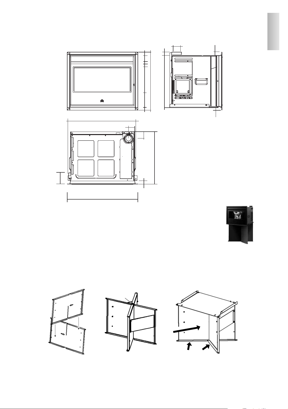
INGOMBRI
ISTRUZIONI MONTAGGIO SUPPORTO OPTIONAL
(non utilizzare in caso di inserimento in un camino esistente)
1) Assemblare le due pareti verticali (ambidestre) secondo figura n° 1.
La freccia indica il verso dal retro verso il fronte.
2) Montare sulle pareti verticali le due alette di rinforzo (A) fissandole con i bulloni in dotazione.
3) Posizionare la piastra di appoggio della PELLINSERT 54 (in dotazione) sulle pareti assemblate di cui al punto 1 e
bloccarla rigidamente mediante i n°4 bulloni in dotazione (fig. n° 2).
4) OBBLIGATORIAMENTE è prescritto di fissare il supporto al pavimento tramite i n°4 tasselli in dotazione (fig. n° 3).
Il non rispetto di quanto sopra, può provocare il ribaltamento di PELLINSERT 54 con gravi danni per l’utilizzatore.
SOLO dopo il fissaggio a pavimento è possibile porre PELLINSERT 54 sopra il supporto.
N.B. per un corretto montaggio, posizionare le pareti in modo che le frecce incise sulle stesse non siamo visibili sul
lato frontale, ma risultino entrambe nella parte posteriore. Inoltre le pieghe delle pareti dovranno essere rivolte
verso il fronte del supporto.
Lato frontale
Pieghe verso il fronte

MONTAGGIO E INSTALLAZIONE (a cura CAT - centro assistenza tecnica autorizzato Edilkamin)
Per quanto non espressamente riportato, in ogni nazione fare riferimento alle norme locali. In Italia fare riferimento
alla norma UNI 10683/2005, nonché ad eventuali indicazioni regionali o delle ASL locali.
VERIFICA DI COMPATIBILITA' CON ALTRI DISPOSITIVI
L’inserto NON deve essere installato nello stesso ambiente in cui si trovano estrattori, apparecchi a gas di tipo B, ect.
Vedi norme UNI 10683/2005 cap. 4.1.
VERIFICA ALLACCIAMENTO ELETTRICO
Pellinsert è fornita di un cavo di alimentazione elettrica da collegarsi ad una presa di 230V 50 Hz, preferibilmente
con interruttore magnetotermico. Variazioni di tensione superiori al 10% possono compromettere l’inserto (se non
già esistente si preveda un interruttore differenziale adeguato). L'impianto elettrico deve essere a norma; verificare
in particolare l’efficienza del circuito di terra. La linea di alimentazione deve essere di sezione adeguata alla potenza dell’inserto.
La non efficienza del circuito di terra provoca mal funzionamento di cui Edikamin non si può far carico.
DISTANZE DI SICUREZZA PER ANTINCENDIO E POSIZIONAMENTO
Per il corretto funzionamento, Pellinsert deve essere posizionata in bolla.
Verificare la capacità portante del pavimento.
Pellinsert deve essere installata nel rispetto delle seguenti condizioni di sicurezza:
- distanza minima sui lati e sul retro di 40 cm dai materiali mediamente infiammabili
- distanza minima sul fronte 80 cm dai materiali mediamente infiammabili
Se non risultasse possibile prevedere le distanze sopra indicate, è necessario mettere in atto provvedimenti tecnici ed
edili per evitare ogni rischio di incendio.
In caso di collegamento su parete in legno o altro materiale infiammabile, è necessario coibentare il tubo di scarico
fumi e le altri parti calde con fibra ceramica o altro materiale di pari caratteristiche.
PRESA D'ARIA
É necessario che venga predisposta dietro l’inserto una presa d’aria collegata con l’esterno, di sezione utile minima di
80 cm2, tale che garantisca all’inserto sufficiente aria per la combustione, senza creare fenomeni di depressione nel loca-
le di installazione.
E possibile collegare direttamente l’aria di combustione con l’esterno, il tubo deve essere di lunghezza inferiore a 1
metro e non deve presentare curve, ponendo però comunque una ulteriore presa aria che colleghi il locale di installazione con l’esterno.
È bene areare l’interno della controcappa dell’eventuale rivestimento immettendo aria dal basso, che per moto convettivo
uscirà da griglie da posizionare alla sommità, consentendo recupero di calore e evitando eccessivi surriscaldamenti.
SCARICO FUMI
Il sistema di scarico deve essere unico per l’inserto (non si ammettono scarichi in canna fumaria comune ad altri focolari).
Lo scarico dei fumi avviene dal bocchettone di diametro 8 cm posto sul coperchio.
Lo scarico fumi deve essere collegato con l'esterno utilizzando idonei tubi in acciaio sigillati ermeticamente.
Per la tenuta dei tubi e il loro eventuale isolamento è necessario utilizzare materiali resistenti almeno a 300°C (silicone o mastici per alte temperature)
L’unico tratto orizzontale ammesso può avere lunghezza fino a 2 mt. evitando contropendenze.
E' possibile un numero di curve fino a due con ampiezza max 45°.
E' necessario (se lo scarico non si inserisce in una canna fumaria) un tratto verticale esterno di almeno 1,5 mt e un
terminale antivento (riferimento UNI 10683/2005 cap. 4.2).
Se lo scarico si inserisce in una canna fumaria, questa deve essere ideonea per combustibili solidi e se è più grande
di 150 mm di diametro, è necessario risanarla intubandola con nuova canna; l’intercapedine risultante tra la nuova e
la vecchia canna fumaria deve essere sigillata con materiale isolante.
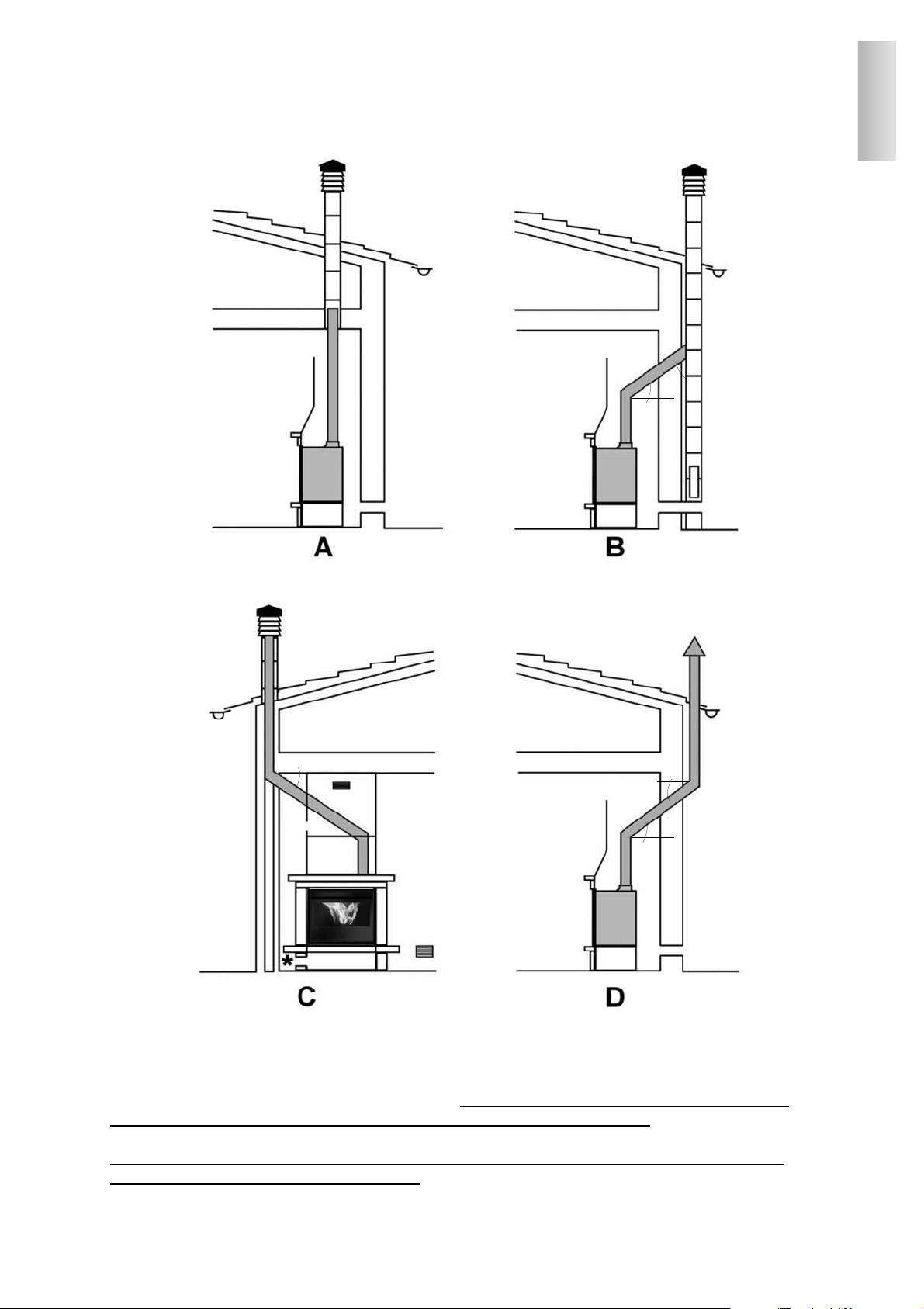
La figura 2 (A-B-C-D), di pag. 7 illustra le tipologie di installazione più frequenti.
6
ITALIANO
7
POSSIBILI INSTALLAZIONI (fig. 2)
A: canna fumaria interna fino al tetto
B: canna fumaria in muratura esterna
C: canna fumaria in muratura interna
D: canna fumaria in acciaio doppia parete esterna (per la seguente installazione è necessario che la
canna fumaria sia a doppia parete e ben coibentata per tutta la sua lunghezza)
* presenza di griglie di ricircolo aria (36x9 cm) in dotazione frontalmente e/o sui lati dell’inserto
** inclinazione max 45° rispetto l’orizzontale
*
*
*
*
*
*
*
*
*
*
*
ITALIANO
8
ITALIANO
CORNICE CONTORNO BOCCA
Pellinsert 54 è dotata di una cornice contorno bocca. Nel caso di installazione in sostituzione di Firebox Edilkamin serie
54 deve essere asportato il profilo (X) che sborda dal traverso inferiore (fig. 6). Detto profilo è predisposto per l’asportazione, è sufficiente fare leva con un cacciavite, dopo aver tolto le viti poste nei 2 angoli.
®
E’ assolutamente necessario prevedere, sul perimetro dell’inserto, lo spazio sufficiente per la circolazione di aria al fine di
evitare eccessi di riscaldamento dello stesso (vedi zona evidenziata con fondo rosa sulla sezione e sulla pianta di pagina
seguente).
Inoltre per favorire la circolazione di aria di cui sopra è altrettanto indispensabile prevedere l’installazione di due griglie :
una alla base del rivestimento (A) ed una nella parte superiore della controcappa (B) vedi pagina seguente.
Pellinsert deve essere installato in modo da poter essere estratto anche a camino rivestito per “eventuali” ispezioni.
1° fase (fig. 1-2)
- Intubare la vecchia canna fumaria in muratura con canna in
acciaio e applicare alla sua base lo spezzone di canale da fumo
(A in dotazione) per collegarsi all’uscita fumi del Pellinsert 54
(che risulterà disassata).
- Installare e fissare con tasselli la piastra di appoggio (B) nella
posizione definitiva che avrà l’inserto.
- Posizionare e fissare (con i bulloni in dotazione) la staffa (C)
di centraggio dello spezzone di canale da fumo (A).
- Calzare lo spezzone di canale da fumo sul collare (D) della
staffa (C) appoggiandolo sulla vite (* fig 2).
A
B
B
C
E
KIT DI FACILITAZIONE PER INSTALLAZIONE IN CAMINETTO CON
RIVESTIMENTO ESISTENTE
(costituito da piastra B e staffa C)
fig. 1
fig. 3
profilo inferiore da rimuovere
fig. 6
X
2° fase (fig. 3)
- Avvolgere lo spezzone di canna o di canale da fumo con un
materassino (G) in più strati di fibra ceramica o materiale
equivalente, in modo tale che lo spessore sia tale da intasare
gli spazi risultanti tra la nuova canna in acciaio e quella esistente in muratura.
- Posizionare l’inserto centrandolo sulla piastra di appoggio
(B) spingendolo fino a fine corsa.
3° fase (fig. 4-5)
- Togliere la vite di appoggio (*) e innestare il canale da fumo
sul bocchettone uscita fumi (F), bloccandolo con la vite (°) .
- L’operazione viene effettuata agendo attraverso l’apertura
(E) prevista sul top dell’inserto, dopo aver tolto la piastrina
(E1) fissata da 2 viti (vedi fig. 2).
N.B.: PER INSTALLAZIONI CON RIVESTIMENTI DI NUOVA REALIZZAZIONE DEVONO
COMUNQUE ESSERE TENUTE IN EVIDENZA LE RACCOMANDAZIONI DI CUI SOPRA
D
E
E1
fig. 2
*
materassino
canna acciaio
G
E
A
fig. 5
*
F
°
fig. 4
9
NOTE SUL MONTAGGIO DEL RIVESTIMENTO
Per definire l'esatto posizionamento del Pellinsert 54 è importante verificare con quale rivestimento verrà completato.
In base al modello prescelto, la collocazione dovrà essere eseguita in modo differente (consultare le istruzioni di montaggio contenute nella confezione di ciascun rivestimento).
Durante l'installazione verificare sempre piombo e livello.
Rivestimenti, controcappe e loro areazioni
Prima di installare il rivestimento verificare la corretta funzionalità dei collegamenti, dei comandi e tutte le parti in movimento.
La verifica va eseguita a inserto acceso ed a regime per alcune ore, prima di installare il rivestimento al fine di poter eventualmente intervenire.
Di conseguenza, le operazioni di finitura, quali ad esempio (costruzione della controcappa, montaggio del rivestimento,
esecuzione di lesene, tinteggiature, ecc.) vanno eseguite a collaudo ultimato con esito positivo.
Edilkamin non risponde quindi degli oneri derivati sia da interventi di demolizione che di ricostruzione anche se conseguenti a lavori di sostituzioni di eventuali pezzi dell’inserto difettosi.
Le eventuali parti in legno del rivestimento devono essere protette da pannelli ignifughi, non presentare punti di contatto con l’inserto, ma essere opportunamente distanziate da quest'ultimo almeno 1 cm ca. per consentire un flusso di aria
che impedisca accumulo di calore.
La controcappa può essere realizzata con pannelli ignifughi in cartongesso o lastre in gesso; durante la realizzazione
devono essere previste le griglie di circolazione dell’aria come precedentemente indicato.
Durante la realizzazione del rivestimento è fondamentale garantire il ripristino dell’aria
di combustione per evitare fenomeni di depressione nell’ambiente di installazione
(vedi capitolo presa aria esterna a pag. 6)
Oltre a quanto sopra, tenere in considerazione quanto indicato dalla norma UNI 10683/2005 ai paragrafi 4.4 e 4.7
"coibentazione, finiture, rivestimenti e raccomandazioni di sicurezza"
N.B: IMPORTANTE PER LE CONDIZIONI DI INSTALLAZIONE
5 cm
5 cm
5 cm
Uscita aria calda
dal frontale
Uscita aria calda
ambiente da ricircolo
all’interno del rivestimento
entrata aria di
ricircolo ambiente
SEZIONE
PIANTA
ITALIANO
A
B
E’ assolutamente necessario prevedere, sul perimetro
dell’inserto, lo spazio sufficiente per la circolazione di
aria al fine di evitare eccessi di riscaldamento dello
stesso (vedi zona evidenziata con fondo rosa sulla
sezione e sulla pianta).
Inoltre per favorire la circolazione di aria di cui sopra è
altrettanto indispensabile prevedere l’installazione di
due griglie : una alla base del rivestimento (A) ed una
nella parte superiore della controcappa (B).
5 cm
Collegamento presa esterna Ø 10 cm
Collegamento
presa esterna
Ø 10 cm
RADIOCOMANDO
Serve per gestire tutte le funzioni per l’utilizzo, non è necessario puntarlo direttamente verso l’inserto.
Legenda tasti e dispaly:
: per accendere e spegnere (per passare da radiocomando stand by a radiocomando attivo)
+/- : per incrementare / decrementare le diverse regolazioni
A : per selezionare il funzionamento Automatico
M : per selezionare il funzionamento Manuale e per accedere ai menù di controllo e programmazione
10
- icona lampeggiante: radiocomando in ricerca di rete
- icona fissa: radiocomando con collegamento attivo
batteria scarica
(n°3 pile alkaline mini stilo AAA
)
tastiera bloccata (premere “A” e “M” in contemporanea
per qualche secondo per bloccare o sbloccare la tastiera)
programmazione attivata
indicatore livello di velocità dei ventilatori
- icona lampeggiante: Inserto in fase di accensione
- icona fissa: Inserto in fase di lavoro
funzione automatica
(appare sul display il valore della temperatura)
display alfanumerico composta da 16 cifre
disposte in due righe da 8 cifre ciascuna
funzione di regolazione manuale
(appare sul display il valore della potenza di lavoro)
indicatore di temperatura
Sul display si visualizzano altre informazioni utili, oltre alle icone descritte sopra.
- Posizione Stand-by:
si visualizza la temperatura ambiente (20°C), i Kg di pellet rimasti (15Kg) nel serbatoio e l'ora corrente (15:33)
- Fase di lavoro manuale:
si visualizza la potenza impostata (Power 1), il livello di ventilazione impostata (F2), la temperatura ambiente (20°C),
i Kg di pellet e l'autonomia residua (15Kg 21H)
- Fase di lavoro automatica:
si visualizza la temperatura impostata (Set 22°C), la temperatura ambiente (20°C), i Kg di pellet e l'autonomia residua
(15Kg 21H).
ITALIANO

11
Prima di accendere.
1° Accensione: rivolgersi al CAT, centro assistenza tecnica di zona autorizzato Edilkamin (per informazioni consultare
il sito www.edilkamin.com), che tarerà l’inserto in base al tipo di pellet disponibile e alle condizioni di uso.
Durante le prime accensioni si potranno sviluppare leggeri odori di vernice che scompariranno in breve tempo.
Prima di accendere è necessario verificare:
• La corretta installazione
• L'alimentazione elettrica.
• La corretta chiusura della porta.
• La pulizia del crogiolo
• Indicazione di stand by sul display del radiocomando (data, potenza o temperatura lampeggianti)
Riempimento coclea.
Al primo utilizzo o in caso di svuotamento completo del serbatoio del pellet, per riempire la coclea premere contemporaneamente i tasti “
+” e “–” dal radiocomando, per qualche secondo; dopo di che, lasciati i tasti, a display compare la
scritta “RICARICA”.
L’operazione è da eseguirsi prima dell’accensione se l’inserto si è fermato per esaurimento pellet, a fine operazione
svuotare il crogiolo prima di accendere.
E’ normale che nel serbatoio resti una quantità residua di pellet che la coclea non riesce ad aspirare.
Accensione automatica
Ad inserto in stand by, premendo per 2" il tasto , sul radiocomando, si avvia la procedura di accensione e viene
visualizzata la scritta “AVVIO”, contemporaneamente ha inizio un conto alla rovescia in secondi (da 1020 a 0). La fase
di accensione non è tuttavia a tempo predeterminato: la sua durata è automaticamente abbreviata se la scheda rileva il
superamento di alcuni test.
Dopo circa 5 minuti compare la fiamma.
Accensione manuale
In casi di temperatura sotto i 3°C che non permetta alla resistenza elettrica di arroventarsi a sufficienza o di temporanea
non funzionalità della resistenza stessa, è possibile usare per l'accensione della “diavolina”.
Introdurre nel crogiolo un pezzetto di “diavolina” ben accesa, chiudere la porta e premere dal radiocomando.
REGOLAZIONE POTENZA
• Funzionamento manuale da radiocomando
A inserto in funzione, premendo una volta il tasto "M" sul radiocomando viene visualizzata a display la scritta “POTENZA P”
(con indicazione della potenza in cui l’inserto sta lavorando), premendo i tasti “
+” o “–” è possibile incrementare o
decrementare la potenza di lavoro dell’inserto (da “POTENZA P1” a “POTENZA P3” ).
•
Funzionamento automatico da radiocomando
Premendo il tasto "A" si commuta a funzionamento automatico regolando la temperatura che si vuole raggiungere nel
locale (per impostare la temperatura da 5°C a 35°C utilizzare i tasti “
+” e “–” e l’inserto regola la potenza di lavoro per
raggiungere la temperatura impostata.
Se si imposta una temperatura inferiore a quella del locale, l’inserto rimarrà in “POTENZA P1”.
Regolazione ventilazione da radiocomando
Premendo il tasto "M" si passa a regolare, a inserto in funzione, la ventilazione (nei 9 livelli associati a tre a tre ai
livelli di potenza) coi tasti “
+” e “–”.
Spegnimento
A inserto funzionante premendo per 2" il tasto dal radiocomando si avvia la procedura di spegnimento sul display
viene visualizzato il conto alla rovescia da 600 a 0 (per un totale di 600 secondi).
La fase di spegnimento prevede:
• Interruzione caduta pellet.
• Ventilazione al massimo.
• Motore espulsione fumi al massimo.
Non staccare mai la spina durante la fase di spegnimento.
MODALITA’ DI FUNZIONAMENTO
ITALIANO

12
OPERAZIONI EFFETTUABILI SOLO CON RADIOCOMANDO
Regolazione orologio
Premendo per 2" il tasto "M" si accede al Menù “OROLOGIO” che consente di impostare l’orologio interno alla
scheda elettronica.
Premendo successivamente il tasto "M", appaiono in sequenza e possono essere regolati i seguenti dati:
Giorno, Mese, Anno, Ora, Minuti, Giorno della settimana.
La scritta SALVATAGGIO?? da confermare con "M" permette di verificare l'esattezza delle operazioni compiute prima
di confermarle (viene allora visualizzato sul display la scritta Salvataggio).
Programmatore orario settimanale
Premendo per 2 secondi il tasto "M" dal radiocomando si accede alla regolazione dell’orologio e premendo il tasto “+”
si accede alla funzione di programmazione oraria settimanale, identificata sul display con la descrizione "PROGRAM.
ON/OFF".
Questa funzione permette di impostare un numero di accensioni e spegnimenti al giorno (fino a un massimo di tre) in
ognuno dei giorni della settimana.
Confermando a display col tasto "M" appare una delle seguenti possibilità:
NO PROG ( nessun programma impostato)
PROGRAMMA GIORN. (unico programma per tutti i giorni)
PROGRAMMA SETT. (programma specifico per ogni singolo giorno)
Con tasti “
+” e “–” si passa da un tipo di programmazione all’atro.
Confermando col tasto "M" l'opzione "PROGRAMMA GIORN." si accede alla scelta del numero di programmi (accensioni/spegnimenti) eseguibili in un giorno.
Utilizzando "PROGRAMMA GIORN." il programma/i impostato/i sarà lo stesso per tutti i giorni della settimana.
Premendo successivamente il tasto “
+” si possono visualizzare:
- NO PROG.
- 1° progr. (una accensione e uno spegnimento al giorno), 2° progr. (idem), 3° progr. (idem)
Usare il tasto “
–” per visualizzare in ordine inverso.
Se si seleziona 1° programma viene visualizzata l'ora della accensione.
A display compare: 1 “ACCESO” ore 10; con il tasto “
+” e “–” si varia l’ora e si conferma col tasto "M".
A display compare: 1 “ACCESO” minuti 30; con il tasto “+” e “–” si variano i minuti e si conferma col tasto "M".
Analogamente per il momento dello spegnimento da programmare e per le successive accensioni o spegnimenti
Si conferma premendo "M" all'apparizione della scritta SALVATAGGIO?? sul display.
Confermando "PROGRAMMA SETT. ” si dovrà scegliere il giorno nel quale eseguire la programmazione:
1 Lu ; 2 Ma; 3 Me; 4 Gi; 5 Ve; 6 Sa; 7 Do
Una volta selezionato il giorno, utilizzando i tasti “
+” e “–” e confermando col tasto "M", si proseguirà con la program-
mazione con la stessa modalità con la quale si esegue un "PROGRAMMA GIORN.", scegliendo per ogni giorno della
settimana se attivare una programmazione stabilendone numero di interventi ed a quali orari.
in caso di errore in qualunque momento della programmazione si può uscire dal programma senza salvare premendo tasto
, a display comparirà NO SALVATAGGIO.
Variazione carico pellet
Premendo per due secondi il tasto "M" dal radiocomando e scorrendo le indicazioni del display con i tasti “+” e “–”, si
incontra la descrizione "ADJ-PELLET”.
Confermando questa funzione con il tasto menù si accede ad una regolazione del caricamento del pellet, diminuendo il
valore impostato si diminuisce il caricamento del pellet, incrementando il valore impostato si aumenta il caricamento del
pellet. Questa funzione può essere utile nel caso in cui sia cambiato il tipo di pellet per il quale è stato tarato l’inserto e
sia quindi necessaria una correzione del caricamento.
Se tale correzione non fosse sufficiente contattare il CAT, centro assistenza tecnica autorizzato Edilkamin, per stabilire il nuovo assetto di funzionamento.
Nota sulla variabilità della fiamma
Eventuali variazioni dello stato della fiamma dipendono dal tipo di pellet impiegato, nonché da una normale variabilità della fiamma di combustibile solido e dalle pulizie periodiche del crogiolo che la stufa automaticamente esegue
(NB:che NON si sostituiscono alla necessaria aspirazione a freddo da parte dell'utente prima dell'accensione).
ITALIANO
13
SEGNALAZIONE RISERVA
L’inserto PELLINSERT è dotato di funzione elettronica per il rilevamento del quantitativo di pellet residuo nel serbatoio.
Il sistema di rilevamento, integrato all’interno della scheda elettronica permette di monitorare in qualsiasi momento
quante ore e Kg mancano all’esaurimento pellet .
È importante per il corretto funzionamento del sistema che durante la prima accessione (a cura del CAT) venga eseguito il seguente procedimento.
1° Accensione/Collaudo a cura del Centro Assistenza Tecnica autorizzato Edilkamin (CAT)
La messa in servizio deve essere eseguita come prescritto dalla norma UNI 10683 punto 3.21
Detta norma indica le operazioni di controllo da eseguire sul posto, finalizzate ad accertare il corretto funzionamento del sistema.
Sistema riserva pellet
Prima di attivare il sistema, è necessario caricare nel serbatoio un sacchetto di pellet e utilizzare il PELLINSERT fino ad
esaurimento del combustibile caricato.
Ciò al fine di ottenere un breve rodaggio del sistema.
Dopo di che è possibile riempire completamente il serbatoio e quindi mettere in funzione il PELLINSERT .
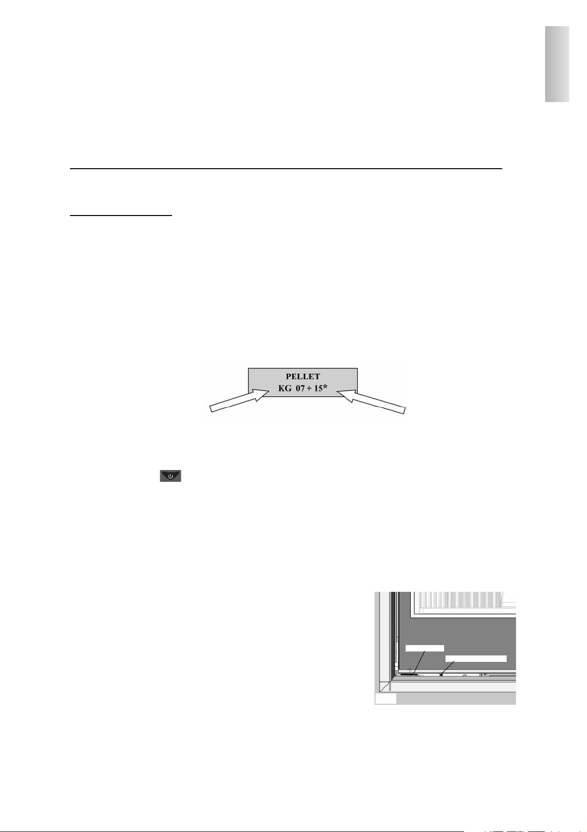
Durante il funzionamento, nel momento in cui sarà possibile caricare un intero sacchetto da 15 Kg di pellet, apparirà a
display, lampeggiando ad intermittenza, la scritta “RISERVA”.
A questo punto dopo aver versato un sacchetto di pellet, è necessario inserire in memoria l’avvenuto carico dei 15 Kg.
A tal fine procedere come segue:
1. premere il tasto "M" (per circa 3-4 secondi) fino alla comparsa della scritta “OROLOGIO”.
2. premere il tasto “
+” fino alla comparsa della scritta “RISERVA”.
3. premere il tasto "M" per la comparsa della seguente videata,
quindi con il tasto “
+” portare la cifra (*) al valore pari ai Kg di pellet caricati (15 kg nel caso sopra ipotizzato).
4. premere il tasto "M" per confermare
5. premere il tasto per uscire.
A seguito dell’effettuazione dell’operazione di cui sopra il sistema dopo il consumo di 15 Kg farà nuovamente apparire
lampeggiando ad intermittenza la scritta “RISERVA”.
Dopo di che dovrà essere ripetuta l’operazione procedendo dal punto 1 al punto 5.
PULSANTE DI EMERGENZA
Nel caso in cui il radiocomando fosse guasto, è possibile accedere alle funzioni di base tramite un pulsante di emergenza
rosso, posizionato sotto il portello esterno, sulla sinistra (vedi fig.7).
Tramite un cacciavite, premere il pulsante una o più volte per attivare la funzione desiderata:
1. A PELLINSERT SPENTA
premendo il pulsante rosso per 2" si accende.
2. A PELLINSERT ACCESA
premendo il pulsante rosso per 2" si spegne.
3. A PELLINSERT ACCESA
modalità manuale, premendo il pulsante rosso si passa da P1 sino a P3.
4. A PELLINSERT ACCESA
modalità automatica, premendo il pulsante rosso si passa da 5°C a 30°C.
ANTENNA RADIO
Pellinsert dialoga con il comando remoto tramite onde radio. Il segnale radio è ricevuto dal radiocomando tramite una piccola antenna posta sotto il portello esterno (vedi fig.7). Nel caso in cui il segnale inviato del radiocomando fosse troppo
debole per la distanza del comando o per altro, è possibile estrarre l’antenna dalla sua sede facendola ruotare su se stessa.
Kg residui nel serbatoio
Kg caricati
fig. 7
pulsante di emergenza
antenna radio
ITALIANO
SEGNALAZIONE EVENTUALI CAUSE DI BLOCCO E CONSIGLI PER POSSIBILI RIMEDI
Indicazioni che si possono visualizzare sul display in caso di spegnimento:
1) Verifica flusso aria : spegnimento per mancanza depressione
(interviene se il sensore di flusso rileva flusso aria comburente insufficiente).
Il flusso può essere insufficiente se c'è portello aperto o tenuta non perfetta del portello stesso (es. guarnizione); se c'è problema di aspirazione aria o di espulsione fumi, oppure crogiolo intasato, oppure sensore di flusso sporco (pulire con aria secca)
Controllare anche soglia del sensore di flusso (nei parametri).
L'allarme depressione può verificarsi anche durante la fase di accensione.
2) Verifica estrattore: spegnimento per anomalia al sensore giri del motore espulsione fumi
(interviene se il sensore giri estrattore fumi rileva un'anomalia)
- Controllare funzionalità estrattore fumi (collegamento sensore di giri)
- Controllare pulizia canale da fumo
3) Stop Fiamma: spegnimento per crollo temperatura fumi
(interviene se la termocoppia rileva una temperatura fumi inferiore a un valore impostato, interpretando ciò come assenza di fiamma) La fiamma può essere mancata perché
- manca pellet
- troppo pellet ha soffocato la fiamma
- è intervenuto il termostato di massima (caso raro, interviene solo in caso di eccessiva temperatura fumi)
4) Blocco AFNO Avvio: spegnimento per temperatura fumi non corretta in fase di accensione
(interviene se in un tempo massimo di 15 minuti non compare fiamma o non è raggiunta la temperatura di avvio).
Distinguere i due casi seguenti:
5) Mancata Energia: spegnimento per mancanza energia elettrica.
Verificare allacciamento elettrico e cali di tensione.
6) Guasto TC: spegnimento per termocoppia guasta o scollegata (interviene se la termocoppia è guasta o scollegata).
Verificare collegamento della termocoppia alla scheda: verificare funzionalità nel collaudo a freddo.
7) ° fumi alta: spegnimento per superamento temperatura massima fumi.
Una temperatura eccessiva dei fumi può dipendere da: tipo di pellet, anomalia estrazione fumi, canale fumi ostruito,
installazione non corretta, "deriva" del motoriduttore.
NOTA 1
Tutte le segnalazioni restano visualizzate fino a che non si interviene sul radiocomando, premendo il tasto .
Si raccomanda di non far ripartire l’inserto prima di aver verificato l'eliminazione del problema.
Nel caso di avvenuto blocco, per riavviare l’inserto è necessario lasciar avvenire la procedura di spegnimento (600
secondi con riscontro sonoro) e quindi premere il tasto .
Non staccare mai la spina durante lo spegnimento per blocco.
Importante riferire al CAT ( centro assistenza tecnica ) cosa segnala il pannello.
NOTA 2
Dopo 2500 kg di pellet consumati, a display compare lampeggiante la scritta “manutenzione”.
L’inserto funziona, ma è necessario far eseguire dal CAT abilitato una manutenzione straordinaria.
NON è comparsa fiamma
E’ comparsa fiamma ma dopo la scritta Avvio è
comparso Blocco AFNO Avvio
Verificare:
- corretto posizionamento e pulizia del crogiolo
- funzionalità resistenza
- temperatura ambiente (se inferiore 3°C) e
umidità.
Provare ad accendere con diavolina
Verificare:
- funzionalità termocoppia
- temperatura di avvio impostata nei parametri
14
ITALIANO

15
CONSIGLI IN CASO DI INCONVENIENTE
ITALIANO
PROBLEMA CAUSA SOLUZIONI
radiocomando inefficiente
- distanza eccessiva dall’inserto
- pile scariche
- avvicinarsi all’inserto
- sostituire con pile alkaline
( n° 3 mini stilo AAA)
aria in uscita non calda
eccessivo deposito di fuliggine nello
scambiatore
pulire lo scambiatore dall' interno del
focolare
non compare la fiamma (ricordarsi
che comunque compare dopo 5
minuti dalla pressione del tasto
on/off)
non è stato effettuato riempimento
coclea
Effettuare riempimento coclea
(vedere paragrafo su accensione)
mancata accensione accumulo di incombusti nel crogiolo pulire crogiolo
“Error rtc-rd” visualizzato sul
pannello sinottico
batteria tampone scarica,
all’interno della scheda elettronica
sostituire batteria tampone
Non "parte" la fase
di accensione/spegnimento
all'ora voluta
Errata impostazione:
ora corrente
attivazione programmi
attivazione del programma nel giorno
Verificare secondo indicazioni
della presente scheda
N.B.:
I comignoli e condotti di fumo ai quali sono collegati gli apparecchi utilizzatori di combustibili
solidi devono venire puliti una volta all’anno (verificare se nella propria nazione esiste una normativa al riguardo).
Omessi il controllo e la pulizia regolari si aumenta la probabilità di un incendio del comignolo.
In quel caso procedere come segue:
non spegnere con acqua;
svuotare il serbatoio del pellet;
rivolgersi a personale specializzato dopo l’incidente prima di riavviare la macchina.
16
MANUTENZIONE
Una regolare manutenzione è alla base del buon funzionamento dell’inserto
Prima di effettuare qualsiasi manutenzione, disinserire l’apparecchio dalla rete di alimentazione elettrica
PULIZIA GIORNALIERA
La pulizia deve essere effettuata aiutandosi con un aspirapolvere a inserto freddo; l'intera procedura richiede pochi minuti al giorno.
- Aspirare lo sportello, il piano fuoco, il vano attorno al crogiolo dove cade la cenere.
- Togliere il crogiolo e scrostarlo con la spatolina metallica in dotazione, pulire eventuali occlusioni dei fori su tutti i lati.
- Aspirare il vano crogiolo, pulire i bordi di contatto tra lo stesso e la sua sede, rimettere il crogiolo.
- Se necessario pulire il vetro (a freddo).
Non aspirare la cenere calda, compromette l'aspiratore
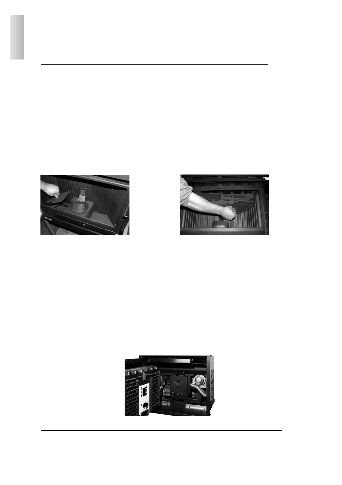
PULIZIA SETTIMANALE
Pellinsert 54 è dotato di due ispezioni sul piano fuoco “A” e di due sul celino del focolare “B" che consentono di intervenire in modo
facile ed efficace per la pulizia del condotto fumi, che deve essere inderogabilmente eseguita.
- svuotare il serbatoio e aspirarne il fondo in caso di inattivita’ della stufa e comunque ogni 15 giorni.
PULIZIA STAGIONALE (a cura del CAT - centro assistenza tecnica autorizzati Edilkamin)
Dopo un consumo di 2500 kg di pellet appare la scritta “manuntezione” che ne indica la necessità e che consiste in:
- Pulizia generale interna ed esterna
- Pulizia accurata dei tubi di scambio
- Pulizia accurata e disincrostazione del crogiolo e del relativo vano
- Pulizia ventilatori, verifica meccanica dei giochi e dei fissaggi
- Pulizia canale da fumo (eventuale sostituzione della guarnizione sul tubo scarico fumi)
- Pulizia del vano ventilatore estrazione fumi, del sensore di flusso, controllo termocoppia.
- Pulizia, ispezione e disincrostazione del vano della resistenza di accensione, eventuale sostituzione della stessa
- Ispezione visiva dei cavi elettrici, delle connessioni e del cavo di alimentazione
- Pulizia serbatoio pellet e verifica giochi dell’assieme coclea-motoriduttore
- Eventuale sostituzione della guarnizione portello
- Collaudo funzionale, caricamento coclea, accensione, funzionamento per 10 minuti e spegnimento
Se vi è un uso molto frequente dell’inserto, si consiglia la pulizia del condotto fumi ogni 3 mesi.
LA MANCATA MANUTENZIONE STAGIONALE IMPLICA LA DECADENZA DELLA GARANZIA.
“A”
“B”
ITALIANO
OPTIONAL:
ACCENSIONE TELEFONICA A DISTANZA (cod. 281900)
E’ possibile ottenere l’accensione a distanza facendo collegare un combinatore telefonico alla scheda elettronica
(rivolgersi a Centro Assistenza Tecnica autorizzato Edilkamin o Rivenditore).
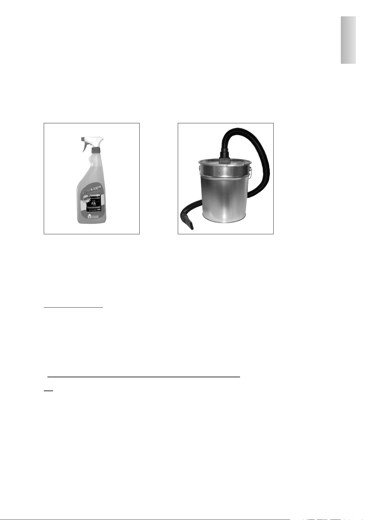
ACCESSORI UTILI PER LA PULIZIA
17
GlassKamin
Bidone aspiracenere
ITALIANO
CHECK LIST
Da integrare con la lettura completa della scheda tecnica
Posa e messa in servizio
• Installazione effettuata da CAT Centro Assistenza Tecnico abilitato Edilkamin che ha rilasciato la garanzia e il libretto di manutenzione
• Aerazione nel locale
• Il canale da fumo/ la canna fumaria riceve solo lo scarico dell’inserto
• Il canale da fumo (collegamento Pellinsert/canna fumaria) presenta:
• massimo 2 curve - massimo 2 metri in orizzontale
• comignolo oltre la zona di reflusso
• la canna fumaria è realizzata con materiale idoneo (consigliato acciaio inox)
• nell’attraversamento di eventuali materiali infiammabili (es. legno) sono state prese tutte le precauzioni per evitare incendi
• presenza sulla controcappa di griglie di ricircolo aria (36 x 9 cm) in dotazione
Uso
• Il pellet utilizzato è di buona qualità e non umido (umidità max 8%)
• Il crogiolo e il vano cenere sono puliti
• La pulizia vetro deve avvenire sempre a freddo
• Il portello deve essere ben chiuso
• Il crogiolo deve essere ben inserito nell’apposito vano
RICORDARSI di ASPIRARE il CROGIOLO PRIMA DI OGNI ACCENSIONE
In caso di fallita accensione, prima di ripetere l’accensione svuotare il crogiolo.

18
Dear Sir/Madam
Thank you for choosing Pellinsert 54.
Before using the insert, please read this information carefully. It is important for an optimal, safe use of all product characteristics.
Please do not hesitate to contact your local retailer for any clarification or other requirements. Alternatively visit the Dealer.
Remember that the very first ignition MUST be carried out by a Dealer, who will check installation and calibrate as necessary (standard UNI 10683 rev. 2005), in addition to completing and activating the warranty.
All incorrect installation, incorrectly performed maintenance or improper use of the product relieves the manufacturer from any
liability for damages deriving from use.
SAFETY INFORMATION
• PELLINSERT 54 has been designed to heat the room it stands in by radiation and air movement.
The hot air is released from the front part of the insert indirectly, making for great user comfort.
• The only risks that may derive from insert use arise through lack of compliance with installation regulations, direct
contact with powered electrical parts (internal), contact with the fire or hot parts (glass, pipes, hot air output), or from the
introduction of items into the hearth.
•Only use wood pellets with 6 mm diameter, as fuel.
• Should a failure occur, the insert is equipped with safety devices to guarantee its automatic switch-off.
This entails no efforts by the user.
• For correct function, the insert must be installed in compliance with the instructions given on this technical sheet.
• The door must not be opened during function: combustion is fully automatic and requires no manual intervention.
• Only use pellets as fuel: under no circumstances should any other substances be introduced into the hearth or tank.
• Do not use flammable products to clean the smoke paths.
• Only use a vacuum cleaner to clean the parts of the hearth and tank.
• Glass can be cleaned COLD with a specific product (e.g. GlassKamin) and a cloth. Do not clean when hot.
• The insert must be laid and ignited by an EDILKAMIN Dealer, authorised to fill out the warranty. These are the only
conditions under which the warranty will be validated.
• During insert function, the exhaust pipes and door become very hot (inform children).
• Do not place any objects that are not heat resistant in the immediate vicinity of the insert. See minimum distances as
given on page 25.
• NEVER use liquid fuels to ignite the insert or revive cinders.
• Do not block ventilation apertures in the installation room, nor the insert air intakes.
• Do not bathe the insert. Do not approach electrical parts with wet hands.
• Do not use reducers on the smoke exhaust pipe.
• The insert must be installed in rooms suitable for fire prevention and equipped with all services (supply and discharges)
required by the appliance to function correctly and safely.
Should ignition fail, DO NOT re-ignite until you have emptied the combustion chamber.
ENGLISH
The undersigned EDILKAMIN S.p.a. with head offi ce headquarters at Via Vincenzo Monti 47 - 20123 Milan - Italy - VAT T00192220192
Declares under its own responsability as follows:
The wood pellet fireplace illustrated below conforms to Regulation EU 305/2011 (CPR) and to the harmonised European Standard
EN 14785:2006
WOOD PELLET FIREPLACE, trademark EDILKAMIN, called PELLINSERT 54
Year of manufacture: Ref. Data nameplate Declaration of performance (DoP - EK 038): Ref. data tag plate
In addition, it is hereby declared that:
the wood pelletfireplace PELLINSERT 54 is in compliance with the requirements of the European directives:
2006/95/EC - Low voltage directive
2004/108/EC - Electromagnetic compatibility directive
EDILKAMIN S.p.a. will decline all responsability of malfunctioning or damage to the equipment in case of unauthorized
substitution, assembly or modifi cations of any sort on the said equipment on the part of non-EDILKAMIN personnel.
19
GUIDELINES TO OPERATION
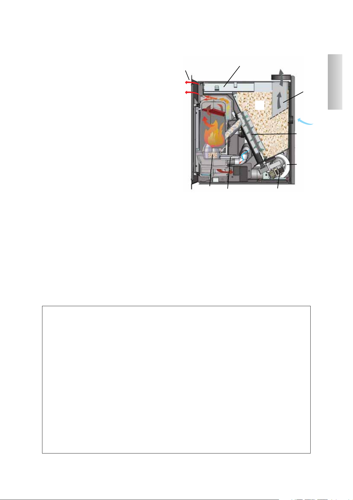
PELLINSERT 54 is an insert that uses pellets as fuel.
Combustion is electronically managed.
The fuel (pellets) is taken from the storage tank (A). A
cochlea (B) is enabled by a gear motor (C), which takes the
fuel to the combustion chamber (D).
The pellets are ignited by hot air produced by an electrical
resistance (E) and suctioned into the combustion chamber by
means of a centrifugal fan.
The smoke produced by combustion is extracted from the
hearth by means of this centrifugal fan and expelled from the
mouth (F) located in the upper area of the insert.
Fans (G) transits air into the hollow space behind the hearth,
where it is heated before being released in the environment
opposite the slits (H).
The fuel tank (A) is situated to the rear of the insert.
The tank is filled through a sliding drawer (I) located in the
front part above the hearth.
The hearth is built with an all-cast iron interior structure, closed to the front by two overlaying doors.
- an external ceramic glass door (to open use the specific
thermal glove).
- an internal door in contact with the fire (to open use the specific cold handle supplied).
Fuel quantity, smoke extraction and combustion air supply
are all regulated by the electronic board, guaranteeing high
performance combustion.
All operations for operation management can be controlled
by the remote control supplied.
Should the remote control be lost or broken, it can also be turned on and off by an emergency button within the insert
(see page 29).
NOTE regarding the fuel.
The PELLINSERT 54 pellet stove is designed and programmed to burn wood pellets with 6 mm diameter.
Pellets are a type of fuel made from compacted sawdust, compressed under high pressure with no adhesive or foreign
materials. They are small in size, approximately 6 mm in diameter and have a cylindrical shape. They are sold in bags
of 15 kg. For the stove to function properly, you MUST NOT burn anything else in it. Using other materials (including wood) will render the warranty null and void. Such use is detected by laboratory analyses.
EdilKamin has designed, tested and programmed their stoves to guarantee the best performance when pellets with
the following characteristics are used:
- diameter: 6 millimetres
- maximum length: 40 mm
- maximum moisture content: 8 %
- calorific value: at least 4300 kcal/kg
If pellets with different characteristics are used, the stove must be recalibrated – a similar procedure to that carried
out by the Dealer when the stove is ignited the first time.
Using unsuitable pellets may:
decrease efficiency; cause malfunctions; stop the stove from functioning due to clogging, dirt on the glass, unburnt
fuel, etc.
A simple, visual analysis of the pellets may be carried out.
Good quality: smooth, uniform length, not very dusty.
Poor quality: horizontal and vertical cracks, very dusty, various lengths and mixed with foreign matter.
ENGLISH
F
A
I
H
D
E
C
G
B
ELECTRICAL CHARACTERISTICS
Power supply 230Vac +/- 10% 50 Hz
Average power consumed 120 W
Power consumed upon
ignition
400 W
Remote control frequency
(as standard)
Radio waves 2.4
GHz
Protection on electronic
board
*
Fuse 2°, 250 V
AC 5x20
SAFETY DEVICES
• THERMO COUPLING:
located on the smoke exhaust, detects the temperature.
On the basis of the parameters set, check the ignition,
working and turn-off phases.
• AIR FLOW SENSOR:
Positioned in the suction channel, this intervenes
when the fuel air flow is incorrect, with consequent
depression problems in the smoke circuit.
• SAFETY THERMOSTAT (150 °C):
Intervenes when the temperature within the boiler is
too high. Blocks pellet loading causing the boiler to
turn off.
DETECTION DEVICES
• ROOM TEMP. DETECTION PROBE:
located on the remote control. Alternatively it can be
connected up to the electronic board inside the insert.
PELLET LOADING
A convenient front drawer allows you to load the pellets in complete comfort, without having to remove
the hearth from its housing, and therefore in absolute
safety and in compliance with standards EN 14785.
BACKUP BATTERY
A backup battery is found on the control board (3Volt CR 2032 battery).
Its malfunction is indicated with the following messages: (not considered a defect but due to normal
wear-and-tear): “Error rtc-rd”.
For more detailed information, please contact the
DEALER who has performed the first 1st ignition.
THERMO TECHNICAL CHARACTERISTICS
Tank capacity 15 kg
Efficiency 89,1 %
Max. power output 8 kW
Available power 6,5 /17 hours
Fuel consumption (min./max.) 0,7 / 1,8 kg/h
Heating capacity *
190 m³
Weight (including packaging) 176 kg
Diameter smoke duct (male) 80 mm
Diameter air intake duct (male) 40 mm
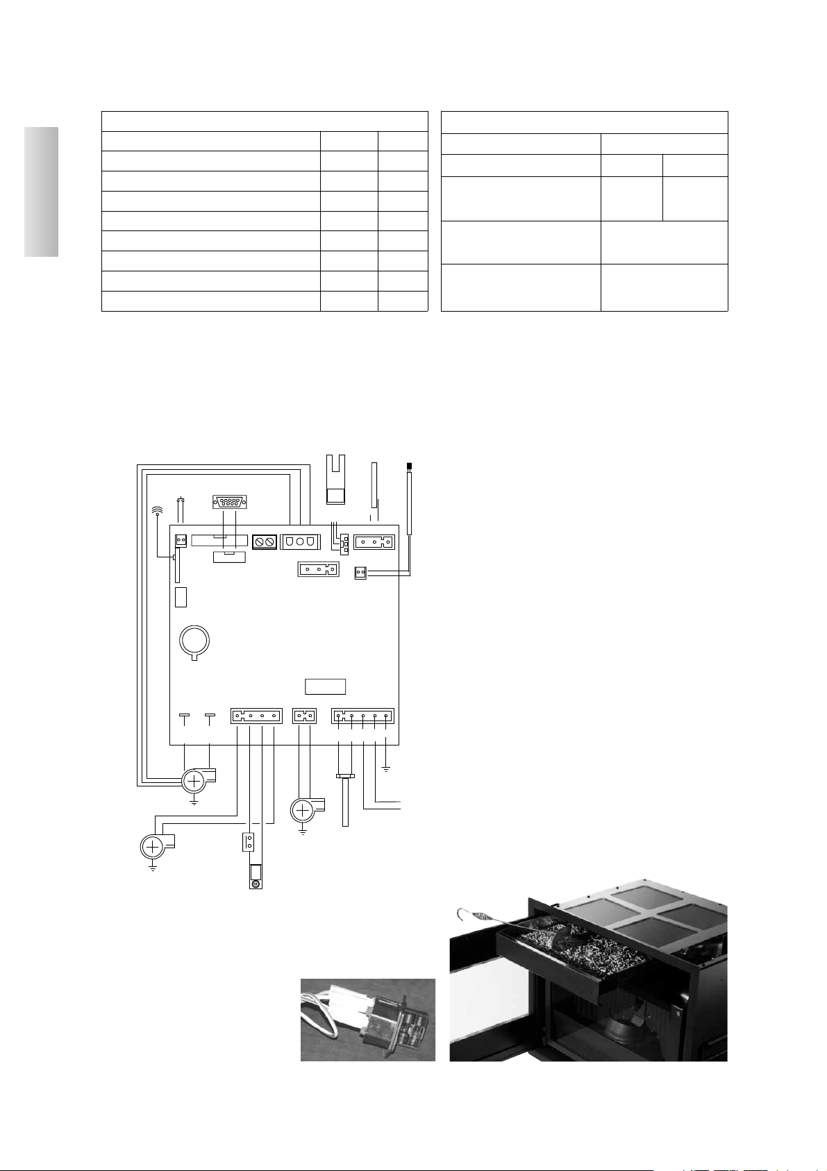
G
L
H
M
N
FLOW
SENSOR
THERMO COUPLING
RS485/AUX
AUX
RPM SMOKE
RS485 SERVICE
IN T° J
RESERVE
SENSOR
(optional)
Room
temperature
PROBE
(optional)
F
R
SOS
AERIAL
D
A
B
C
SMOKE
EXPULSION MOTOR
RES IGNITION
FUSE 2A
E
RIGHT-HAND
VENTILATION
MAINS 230
VAC
50 Hz +/-10%
F
TM 150 °C
LEFT-HAND
VENTILATION
M COCHLEA
lithium
+
CR2032
+-
ENGLISH
20
AUX/RS485 PORT
(connected via optional serial port cable code 621240)
A clean, potential free contact, used to connect a
telephone dialler or other control devices if the optional cable is
not used.
ELECTRICAL DIAGRAM
FUSIBILE
* sulla presa con interruttore posta
sul retro della stufa, sono inseriti due
fusibili, di cui uno funzionale e l'altro di scorta.
*
*
*
The heatable room dimensions are calculated on the basis of pellets with an
lhv of at least 4300 kcal/kg and home insulation in compliance with Italian law
10/91, and subsequent changes together with an expected heat output of 35
Kcal/m³ per hour.
N.B.
1) bear in mind that external devices may cause interference.
2) caution: live parts. Servicing and/or inspections must be carried out by
qualified staff.
G
L
E
+---
C
F
M
ANTENNA
F
R
Lith ium
+
CR2 032
DAB
N
H
ENGLISH
21
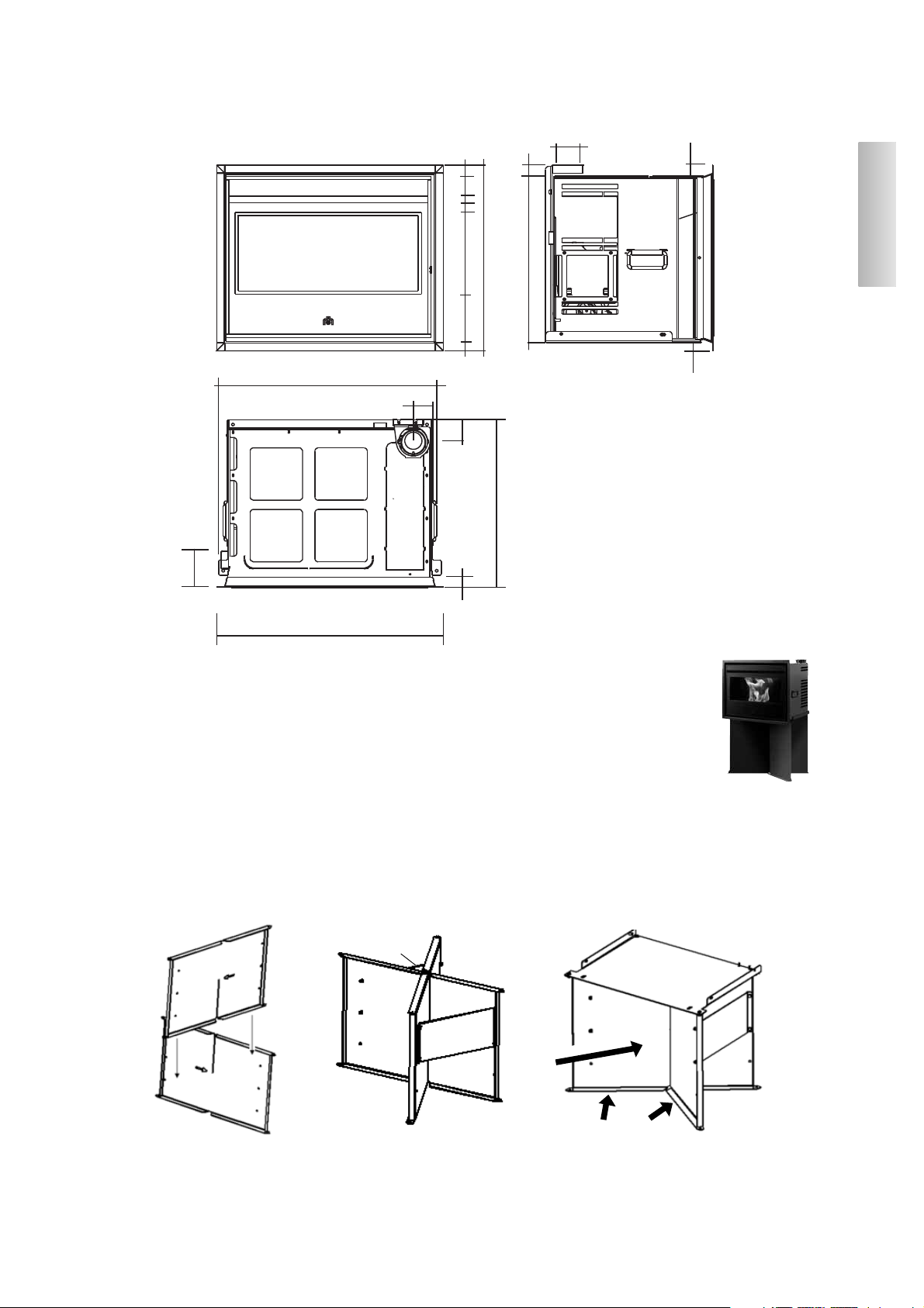
12
3.5
2.5
54
7
6.5
70
73
4
15
26
6
60
3.5
54
12
Ø8
2
3
4
4
*
*
smoke output
A
A
SPACE REQUIRED
OPTIONAL SUPPORT ASSEMBLY INSTRUCTIONS
(do not use where inserting in an existing chimney)
1) Assemble the two vertical walls (works both sides) according to figure no. 1.
The arrow indicates the direction from the back to the front.
2) Assemble the two strengthening flaps (A), fixing them with the bolts supplied.
3) Position the PELLINSERT 54 support plate (supplied) on the assembled walls as per point 1. Block tight using the 4
bolts supplied (fig. no. 2).
4) You MUST fix the support to the floor using the 4 fitting supplied (fig. no. 3).
Failure to comply with the above may cause the PELLINSERT 54 to upturn at serious risk to the user.
ONLY position the PELLINSERT 54 on its support once fixed to the floor.
N.B. For a correct installation, place the walls in such a ways so that the arrows engraved on them are not visible
on the front part; they must both be on the back part. Moreover, the folds of the walls must be directed towards
the front part of the support.
Front part
Folded towards front

ASSEMBLY AND INSTALLATION (by the Dealer)
For anything that is not specifically stated herein, each country should refer to the applicable local regulations. In Italy,
refer to standard UNI 10683/2005 in addition to any regional instructions or local health authority instruction.
CHECKING COMPATIBILITY WITH OTHER DEVICES
The insert must NOT be installed in the same room as type B gas appliances, extractors, etc.
See chap. 4.1 of standard UNI 10683/2005.
CHECKING ELECTRICAL CONNECTION
Pellinsert is supplied with an electrical power lead to be connected up to a 230V 50 Hz socket and preferably with
a thermal magnetic switch. Changes in voltage by more than 10% can affect the insert (if not already in place, use
an appropriate differential switch). The electrical system must be certified as legally compliant. Specifically check
the efficiency of the earth circuit. The power line must be of a section that is appropriate to the insert power.
An inadequate earthing system can cause anomalies for which Edilkamin cannot be held liable.
SAFETY DISTANCE FOR FIRE-PREVENTION AND POSITIONING
To function correctly, Pellinsert must be positioned on the level.
Check that the floor load capacity is sufficient.
Pellinsert must be installed in compliance with the following safety conditions:
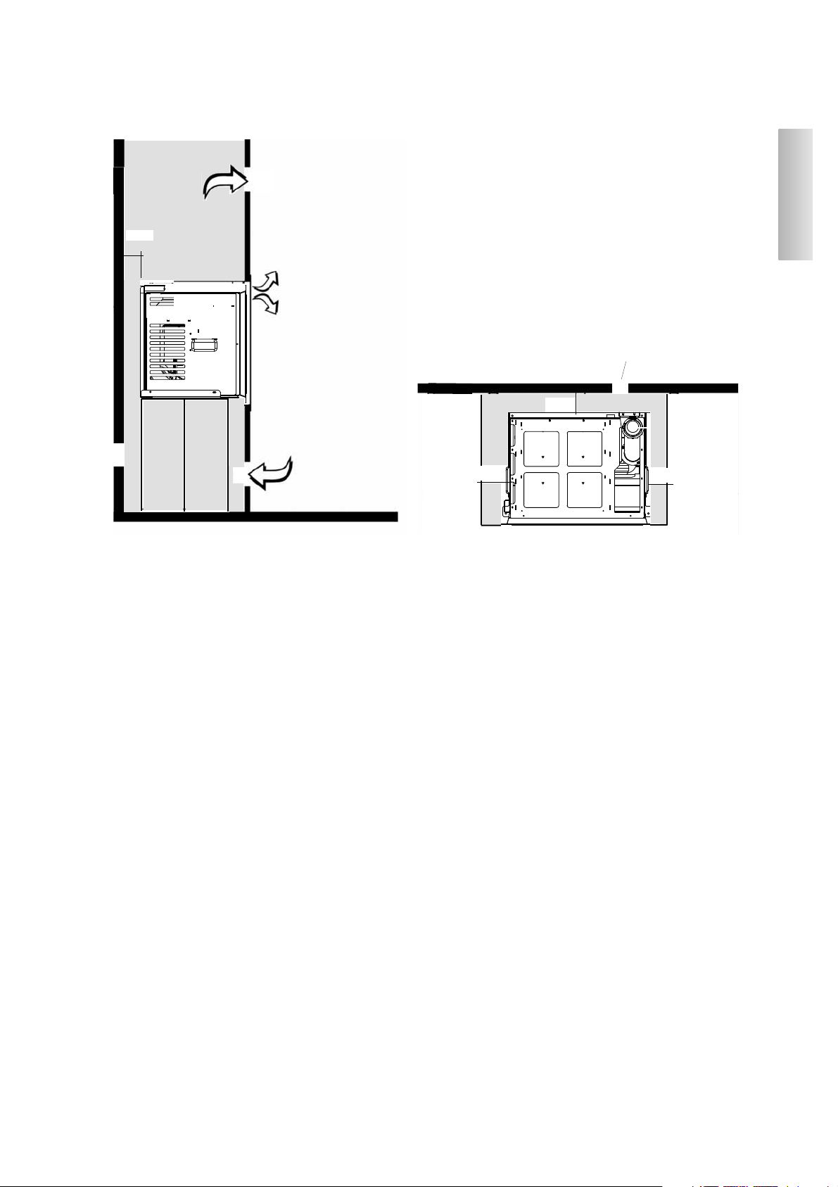
- leave a minimum of 40 cm space to the sides and back from any medium-flammable materials
- leave a minimum of 80 cm space to the front from any medium-flammable materials
If it is impossible to leave the distances given above, technical and construction provisions must be taken to avoid
all fire risk.
If connected to a wooden wall, or wall constructed from another flammable material, the smoke exhaust pipe and
other hot parts must be insulated with ceramic fibre or other, similar materials.
AIR INTAKE
An air intake must be prepared behind the insert and connected with the outside. It must have a useful minimum section
of 80 cm² to guarantee sufficient air to the insert for combustion, without creating depression in the installation room.
The combustion air can be connected directly with the outside by arranging a further air intake connecting the installation
room with the outside. The pipe must be less than 1 metre long and have no bends.
It is best to ventilate the inside of the counter-hood of any covering, putting air in from the bottom. Convection will then
take this out through the grill, which should be positioned at the top, thereby allowing for the recovery of heat and
avoiding any overheating.
SMOKE DISCHARGE
The discharge system must only be used for the insert (no discharge permitted into a chimney flue shared with
other hearths).
Smoke discharge takes place from the mouth on the cover, measuring 8 cm in diameter.
The smoke discharge must be connected with the outside, using suitable sealed steel pipes.
To seal or insulate (where applicable) pipes, materials resistant to at least 300°C must be used (silicone or mastics
for high temperatures).
The only horizontal section allowed may be up to 2 m long, avoiding any counter-slopes.
Up to two curves can be used with a max. width of 45°.
If the discharge is not into a chimney flue, an external vertical stretch will be required of at least 1.5 metres, and a
windproof terminal (reference chap. 4.2 UNI 10683/2005).
If the discharge is into a chimney flue, this must be suitable for solid fuels. If it is more than 150 mm diameter, it
must be re-established by threading it with a new flue. The resulting hollow space between the new and old flue must
be sealed with insulating material.
Figure 2 (A-B-C-D) on page 23 illustrates the most common types of installation.
ENGLISH
22
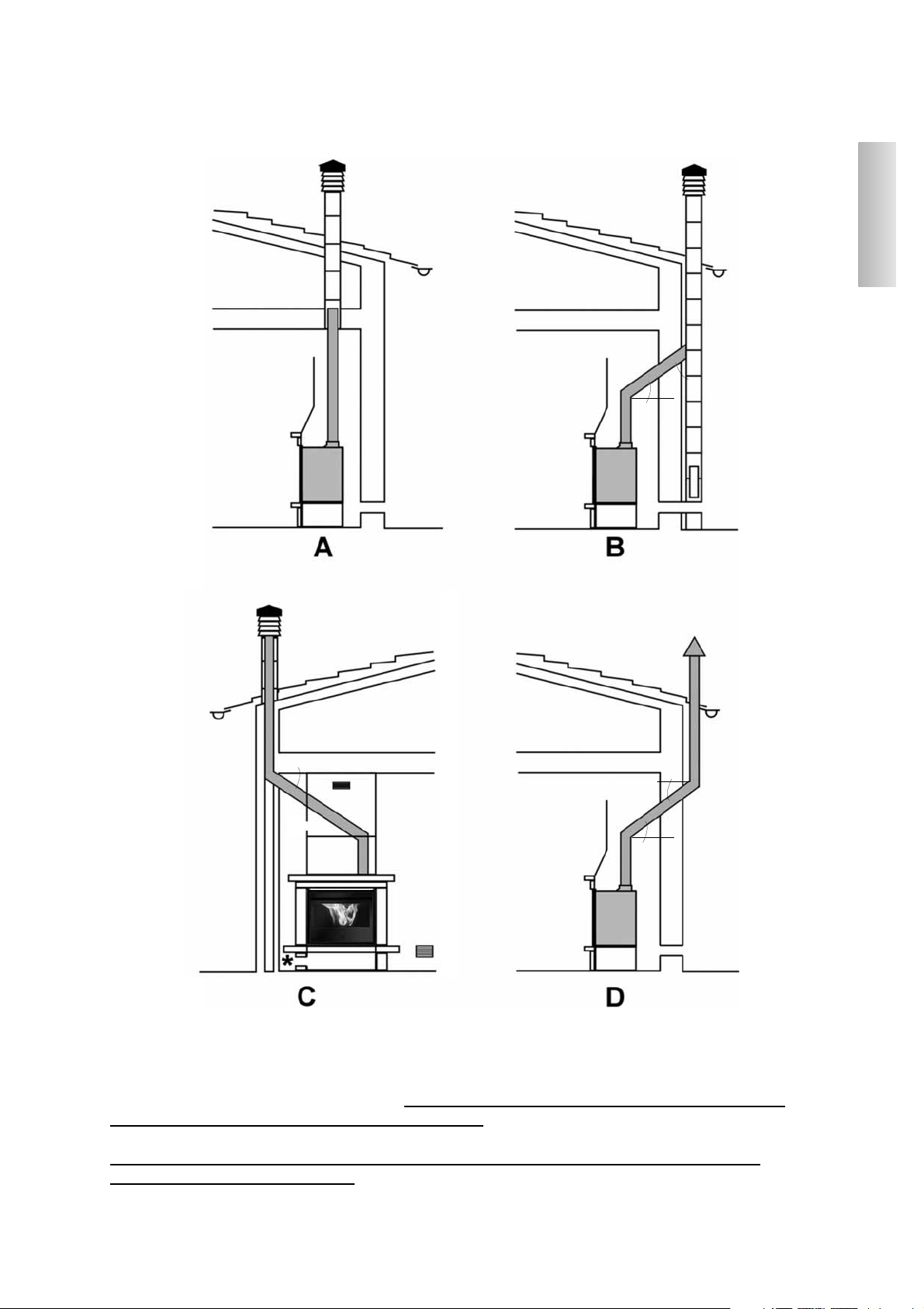
POSSIBLE INSTALLATIONS (fig. 2)
A: internal chimney flue up to the roof
B: external brick-built chimney flue
C: internal brick-built chimney flue
D: double-wall external steel chimney flue (for the following installation, the chimney flue must be
double-walled and well-insulated for the entire length)
* presence of air recirculation grills (36x9 cm) on the front and/or sides of the insert (supplied)
** max. angle 45° to the horizontal.
*
*
*
*
*
*
*
*
*
ENGLISH
23
ENGLISH
24
A
B
B
C
E
fig. 1
fig. 3
fig. 6
X
D
E
E1
fig. 2
*
G
E
A
fig. 5
*
lower profile to be removed
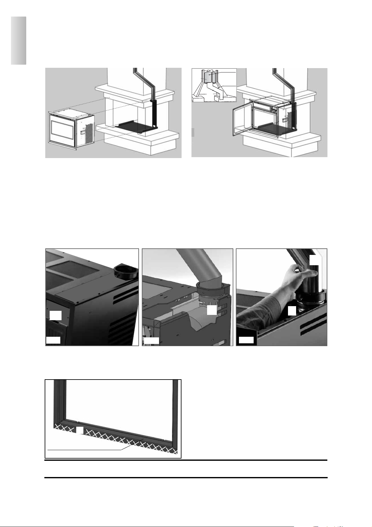
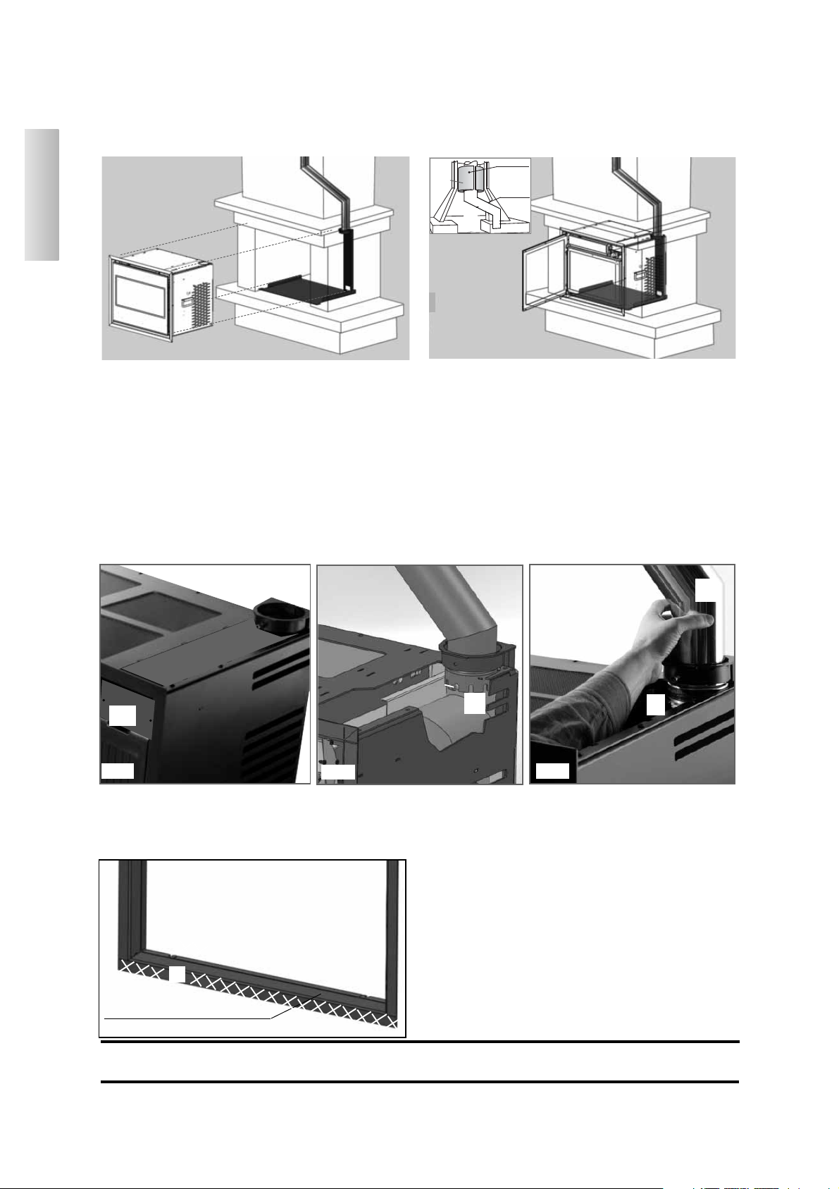
1st step (Figs. 1-2)
- Enter a steel flue into the old masonry chimney flue and
apply the smoke channel supplied (A) to its base, so as to connect it to the Pellinsert smoke outlet (this will be misaligned).
- Install the support plate (B), which will have an insert, and
fasten it into its definite position with dowels.
- Position the centring bracket (C) of the smoke channel (A)
and fasten it with the bolts supplied.
- Fit the smoke channel onto the collar (D) of the bracket (C)
by resting it onto the screw (* fig 2).
EASY INSTALLATION KIT FOR A FIREPLACE WITH AN ALREADY
INSTALLED COVERING
(consisting of plate B and bracket C)
OPENING FRAMEOPENING FRAME
Pellinsert is equipped with an opening frame. When replacing Edilkamin Firebox series 54, profile (X) that extends over
the lower border, must be removed (Fig. 6). This profile can be easily removed by using a screwdriver to lever it after
having removed the screws at both corners.
2nd step (Fig. 3)
- Wrap the flue or smoke channel with a mat, (G) made of a
number of ceramic fibre layers or equivalent material, which
is thick enough to fill the gaps formed between the new steel
flue and that made of masonry.
- Place the inert into the centre of the support plate (B) and
push it until it reaches the end-of-travel.
3° fase (fig. 4-5)
- Remove the support screw (*) and fit the smoke channel onto
the smoke outlet (F), blocking it in place with the screw (°) .
- This is implemented through the opening (E) at the top of the
insert, after having removed the plate (E1) fastened with 2
screws (refer to Fig. 2).
It is absolutely necessary to leave enough space along the
perimeter of the insert for air circulation in order to prevent
this from overheating (refer to the area highlighted with a
pink background on the section and on the plan found on the
following page). Moreover, two grilles must be installed so as
to enhance air circulation: one at the bottom of the covering
(A) and the other on the upper part of the mantel (B) - refer to
the following page. It must be possible to remove Pellinsert
for "possible" inspections after being installed, even if the
fireplace is covered.
N.B.: INSTALLATIONS WITH NEW COVERINGS MUST BE SET UP IN ACCORDANCE WITH
THE ABOVE MENTIONED RECOMMENDATIONS
®
mat
steel rod
F
°
fig. 4
NOTES ON FITTING THE COVERING
In order to define the exact position of the Pellinsert 54, it is important to check which covering will be used to complete it.
Positioning differs according to the model chosen (see assembly instructions given in the packaging of each covering).
Always check that installation is perfectly vertical and horizontal.
Coverings, counter-hoods and their ventilation
Before installing the covering, check that all connections, commands and moving parts are perfectly functional.
Check this with the insert on and working for a few hours. Do so prior to fitting the covering in order to intervene as
necessary.
Finishing works, such as construction of the counter-hood, covering assembly, pilaster preparation, painting, etc., should
be carried out once the final test has been passed.
Edilkamin will therefore not be held liable for any charges deriving from both demolition and reconstruction works, even
where consequent to replacement of any faulty insert parts.
Rather, at least 1 cm. (approx.) space must be left to allow air to flow, thereby preventing heat from accumulating.
The counter-hood can be created from fireproof plasterboard panels or plaster sheets. When creating this, the air
circulation grill must be included, as previously specified.
During the construction phase of the covering it is fundamental to ensure that the combu-
stion air is restored to prevent pressure phenomena in the room where the fireplace is instal-
led (refer to the Chapter regarding the external air inlet on page 22)
In addition to the above, always consider the indications given by paragraphs 4.4 and 4.7 of standard UNI 10683/2005
“insulation, finishes, coverings and safety recommendations”.
ENGLISH
25
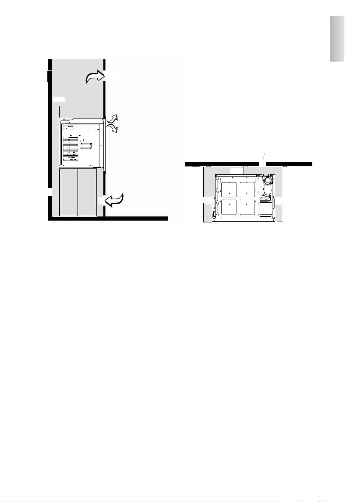
External intake connection Ø 10 cm
N.B.: IMPORTANT FOR INSTALLATION CONDITIONS
5 cm
5 cm
5 cm
Warm air outlet at
the front
A
B
It is absolutely necessary to set up enough space along
the perimeter of the insert for air circulation to prevent
this from overheating (refer to the area highlighted with
a pink background on the section and on the plan).
Moreover, two grilles must be installed in order to
enhance air circulation: one at the bottom of the covering (A) and the other on the upper part of the mantel
(B).
5 cm
inlet for recirculation
of air into the room
Output for recirculation
of hot air within the
covering
SYSTEM
SECTION
External
intake
connection
Ø 10 cm

ENGLISH
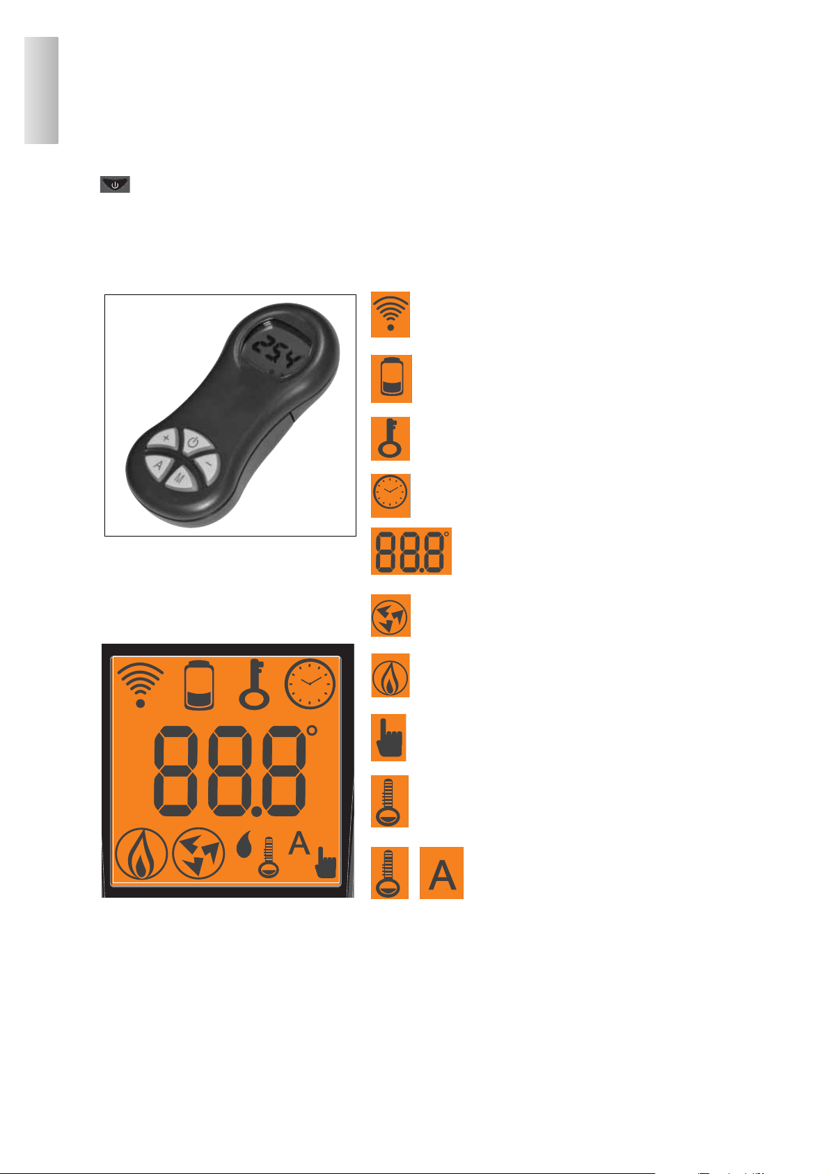
REMOTE CONTROL
This controls all the functions. To use, it’s not necessary tho point directly towards the insert.
Key to buttons and display:
: to turn off and on (to go from remote control on stand-by to remote control on)
+/- : to increase/decrease the various regulations
A : to select Automatic function
M : to select Manual function and access the control and programming menus
- icon flashing: remote control searching for network
- icon fixed: remote control with connection enabled
flat battery
(3 mini alkaline batteries type AAA)
keypad locked
(press "A" and "M" in parallel for a few seconds to lock
or unlock the keypad)
programming enabled
fan speed indicator
- icon flashing: Insert turning on
- icon fixed: Insert working
automatic function
(display shows temperature)
alphanumeric display consisting
of 16 figures arranged in two lines
of 8 figures
manual adjustment function
(display shows working power)
temperature indicator
The display also shows other useful information in addition to the icons described above.
- Stand-by position:
shows room temperature (20°C), kg of pellets (15 kg) remaining in tank and current time (15.33)
- Manual work phase:
shows power set (Power 1), fan level set (F2), room temperature (20°C), kg of pellets and autonomy remaining (15 kg
21 hrs)
- Automatic work phase:
shows temperature set (Set 22°C), room temperature (20°C), kg of pellets and autonomy remaining (15 kg 21 hrs).
26

ENGLISH
Before igniting.
1st ignition: contact your local Dealer.
They will calibrate the insert according to the type of pellets available and the conditions of use.
There may be a slight smell of paint the first few times it is ignited. This will disappear quickly.
Prima di accendere è necessario verificare:
Before igniting, check:
• that installation is correct
• electricity supply
• that the door closes correctly
• that the combustion chamber is clean
• stand-by indicated on the remote control display (date, power or temperature flashing)
Filling the cochlea.
The first time you use the product, or should the tank be completely emptied of pellets, to fill the coclea press both keys
“+” and “–” on the remote control at the same time, holding for a few seconds. As you release the keys, the display
should show the wording “LOAD”.
This should be carried out before ignition if the insert has stopped due to having run out of pellets, at the end of operation
to empty the combustion pot before turning.
It is quite normal for some pellets to remain, that the cochlea cannot suction.
Automatic igniting.
With the insert on stand-by, press and hold the key , on the remote control for 2 seconds. This will start-up the
ignition procedure, showing the wording “START”. At the same time, a countdown in seconds begins (from 1020 to 0).
Ignition is not at a preset time, however: its duration is automatically shortened if the board reports that certain tests have
been passed. The flame appears after about 5 minutes.
Manual igniting.
Temperatures of below 3°C will not allow the electrical resistance to heat sufficiently. In this case, or should the
resistance be temporarily out of action, Diavolina® type fire-starters can be used.
Insert a piece of lit Diavolina® into the combustion chamber, close the door and press the remote control.
POWER REGULATION
• Remote control manual operation
With the insert working, press the key "M" on the remote control once. The display will show the word “POWER P”.
(specifying the power at which the insert is working). Press the keys “+” or “–” to increase or decrease the insert’s
working power (from “POWER P1” to “POWER P3”).
•
Remote control automatic operation
Press key "A" to switch to automatic operation, adjusting the temperature desired for the room (use the “+” and “–” keys
to set the temperature from 5°C to 35°C, and the insert will regulate working power required to reach the temperature
set.
If a temperature below that of the room is set, the insert will stay on “POWER P1”.
Remote control fan regulation
Press the key "M" to regulate the fan whilst the insert is running (9 levels associated in threes to the power levels), using
keys ‘+’ and ‘-‘.
Turning off
With the insert running, press and hold the key from the remote control for 2 seconds. The turn-off procedure will
begin, showing a countdown on the display from 600 to 0 (for a total of 600 seconds).
The turn-off phase involves:
• Interruption of pellet supply
• Maximum ventilation.
• Smoke expulsion motor.
Never pull the plug out whilst the device is still in the process of turning off.
OPERATING MODES
27

ENGLISH
OPERATIONS THAT CAN ONLY BE CARRIED OUT BY REMOTE CONTROL
Clock regulation
Press and hold the key "M" for 2 seconds to access the “CLOCK” menu. This allows you to set the internal electronic board
clock.
By then pressing the key "M", the following data appears in sequence and can be regulated:
day, month, year, hour, minutes, day of the week.
The wording “SAVE??” will appear for confirmation with "M". This will allow you to check that the operations performed are
correct, prior to completion (the wording “SAVE” will then be shown on the display).
Weekly timer
Press and hold the "M" key on the remote control for 2 seconds. This turns on the clock regulation and by pressing the '+'
key, the weekly timer function is accessed, with the display showing the description “PROGRAMM ON/OFF”.
This function allows you to set a number of times the insert turns on and off per day (up to a maximum of three), each
day of the week.
As you confirm the display with the key "M", one of the following options will appear:
NO PROG. (no programme set)
DAILY PROGRAM (single programme for every day of the week)
WEEKLY PROGRAM. (specific programme for each day individually)
Use the “+” and “–” keys to switch between programmes.
Use key "M" to confirm the option “DAILY PROGRAM” to choose the number of programmes (turn on/off) to be carried out per day.
Use the “DAILY PROGRAM” to set identical programme/s for every day of the week.
By then pressing the “+” key, the following can be seen:
- Prog. no.
- 1st prog. (one turn on and one turn off per day), 2nd prog. (identical), 3rd prog. (identical)
Use the “–” key to show in reverse order.
If the 1st programme is selected, the turn on time is shown.
The display shows: 1 “ON” at 10 Use the “+” and “–” key to change the hour. Confirm with the "M" key.
The display shows: 1 “ON” at 30 Use the “+” and “–” key to change the minutes. Confirm with the "M" key.
The same applies for the turn-off time to be set and for subsequent turning on and off.
Confirm by pressing "M" and the wording “SAVE??” will appear on the display.y.
When confirming ”WEEKLY PROGRAM”, you will need to choose the day to which the programming is to apply:
1 Mon ; 2 Tues; 3 Wed; 4 Thurs; 5 Fri; 6 Sa; 7 Sat
Once you have chosen the day, use the “+” and “–” key and confirm with the "M" key, to programme in the same way
as for the “DAILY PROGRAM”, choosing whether or not to enable a programme for each day of the week, and if so
choosing number of interventions and at what times.
Should you make an error during programming, you can leave the programme without saving. As you press a key,
the display will show the word “NO SAVE”.
Changing pellet loading
Press and hold the "M" key on the remote control for two seconds. Scroll through the display instructions using the “+”
and “–” keys, to the description "ADJ-PELLET”.
By confirming this function with the menu key, you can access the function to adjust pellet loading. By decreasing the
value set, pellet loading is decreased. By increasing the value set, pellet loading increases. This function is useful if
changing the pellet type for which the insert has been calibrated and loading therefore needs correcting.
Should this correction not suffice, contact the Edilkamin-authorised Dealer, to establish the new operating axis.
Notes on flame variability
Flame status may vary depending on the type of pellet used, in addition to normal solid fuel flame variability and
regular combustion chamber cleaning carried out automatically by the boiler.
(N.B.: which does NOT replace necessary cold suction by the user prior to ignition).
28
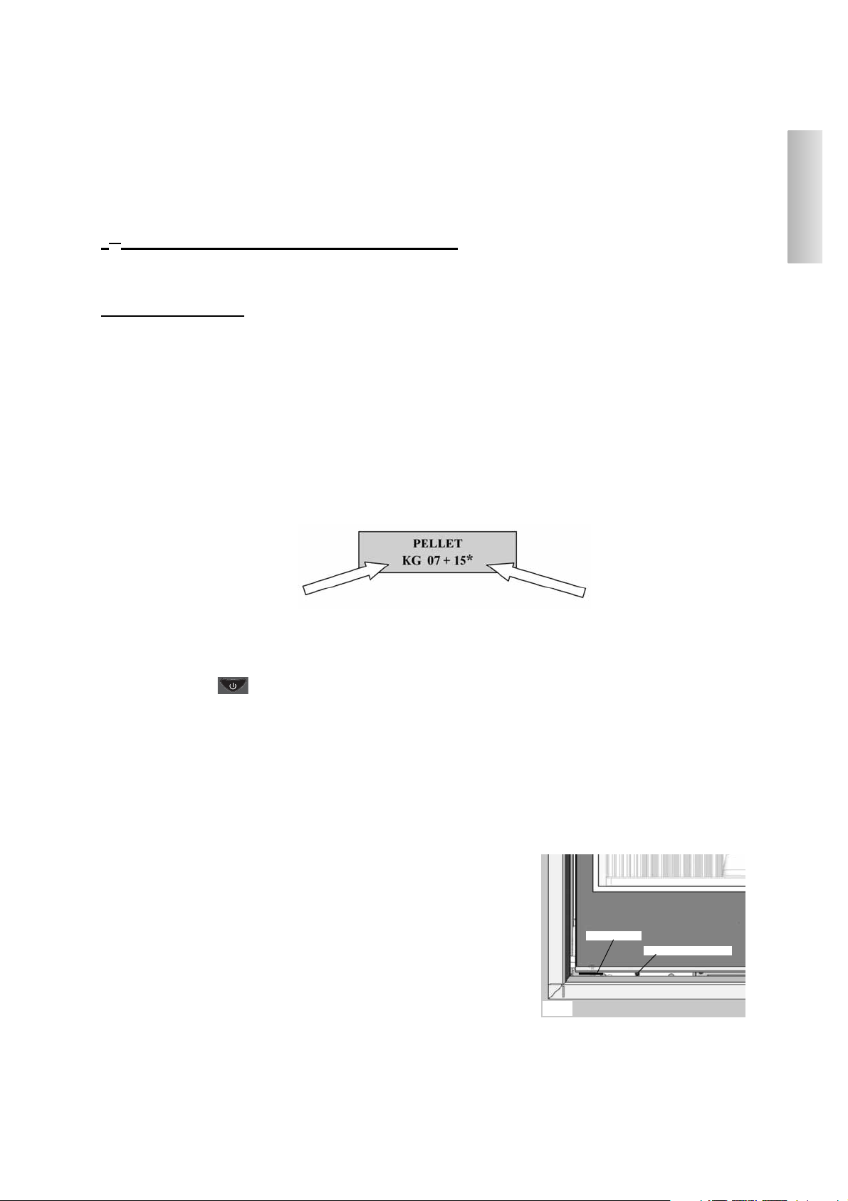
ENGLISH
RESERVE WARNING
The PELLINSERT insert is fitted with an electronic function that detects the residual quantity of pellets in the tank.
The detection system is integrated into the electronic board, allowing you to see how many hours and kg are left until
pellet exhaustion, at all times.
For correct system function, it is important that the following procedure is followed during the first ignition (by the
Dealer).
1st ignition/test by the Edilkamin authorised Dealer
Start-up must be carried out as prescribed by point 3.21 of standard UNI 10683.
This standard indicates the control operations to be carried out in situ, aimed at ascertaining correct system function.
Pellet reserve system
Before enabling the system, you need to load a sack of pellets into the tank and use the PELLINSERT until the loaded
fuel has run out.
This allows for a short system road test.
After this, the tank can be filled completely and the PELLINSERT started up.
When running, at the time at which a whole 15 kg sack of pellets can be loaded, the display will show the word
“RESERVE” flashing.
At this point, after having poured in a sack of pellets, you need to 'inform' the memory that you have loaded 15 kg.
To do so, proceed as follows:
1. press the "M" key (for approximately 3-4 seconds) until the word “CLOCK” appears.
2. press the “+” key until the word “RESERVE” appears.
3. press the "M" key until the following screen appears,
then use the “+” key to take the figure (*) to the value equal to the Kg of pellets loaded (15 kg in the above example).
4. press the "M" key to confirm
5. press the key to exit.
After having completed the above procedure, after having consumed the 15 kg, the wording “RESERVE” will appear
flashing at intervals.
After which the operation must be repeated, from point 1 to point 5.
EMERGENCY BUTTON
Should the remote control be broken, the basic functions can also be accessed by means of a red emergency button
located under the external hatch, on the left (see fig. 7).
Use a screwdriver to press the button once or more to enable the function desired:
1. A PELLINSERT OFF
by pressing the red button for 2 seconds this turns on.
2. A PELLINSERT ON
by pressing the red button for 2 seconds this turns off.
3. A PELLINSERT ON
manual mode, by pressing the red button, you go from P1 to P3.
4. A PELLINSERT ON
automatic mode, by pressing the red button, you go from 5°C to 30°C.
RADIO ANTENNA
Pellinsert dialogues with the remote control by means of radio waves. The radio signal is received by the radio control by
means of a small antenna beneath the external hatch (see fig. 7). Should the signal sent from the remote control be too
weak for the control distance or other reason, the antenna can be removed from its housing by rotating it.
Kg remaining in tank
Kg loaded
fig. 7
emergency button
radio antenna
29
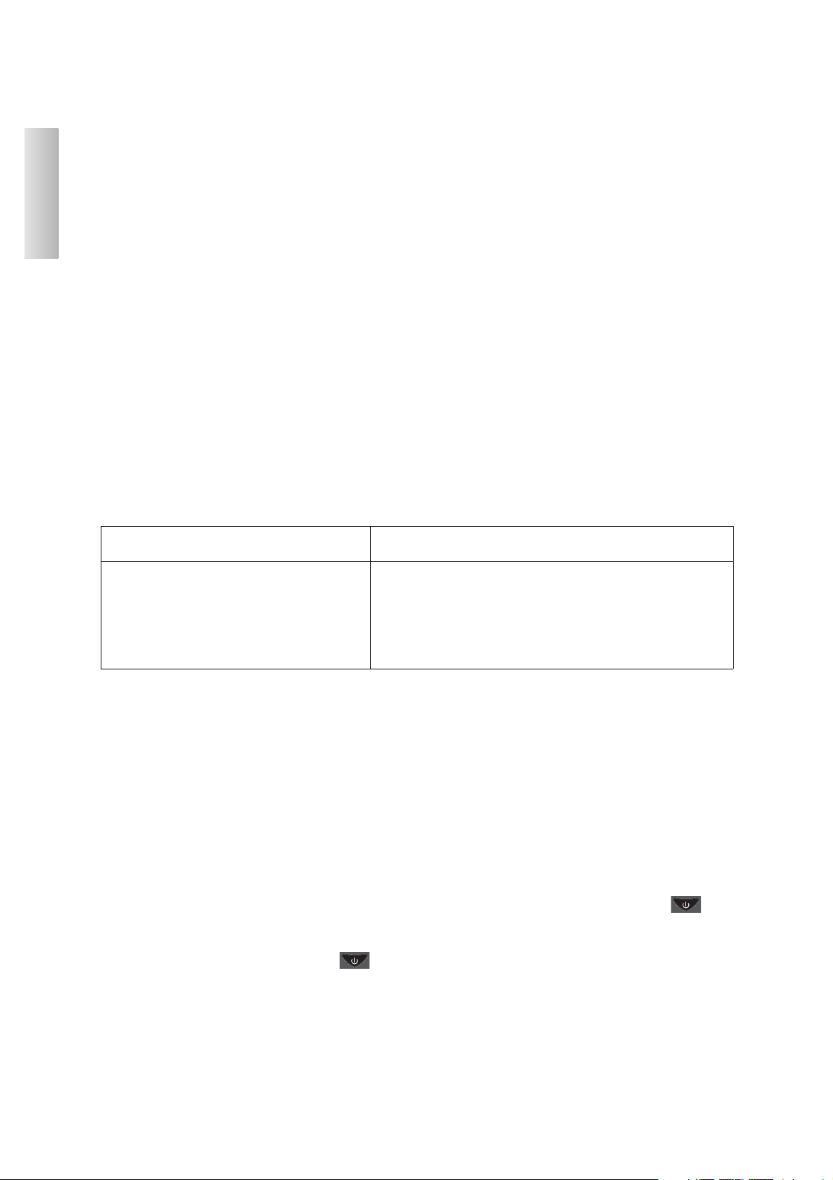
SIGNALLING OF ANY CAUSES OF BLOCKAGE AND ADVICE FOR POSSIBLE
SOLUTIONS
Indications that can be seen on the display should it turn off:
1) Check air flow: turns off for lack of depression (intervenes if the flow sensor detects insufficient combustion air flow).
Flow may be insufficient if there is a hatch open or the hatch is not perfectly sealed (e.g. seal flawed). This may also be
the case if there is a problem with air intake or smoke extraction, or if the combustion chamber is blocked or the flow
sensor dirty (clean with dry air).
Also check that the flow sensor limits are within the parameters.
The depression alarm may also be signalled during ignition.
2) Check Expulsi : turns off due to smoke expulsion motor (intervenes if the smoke extractor revolutions sensor detects
an anomaly)
- Check smoke extractor function (devolution sensor connection)
- Check smoke channel for dirt
3) Stop Fire: turns off due to drop in smoke temperature (intervenes if the thermo coupling reports a smoke
temperature below a value set, thereby interpreting it as a lack of flame). Flame may fail for any of the following reasons:
- lack of pellets
- too many pellets have suffocated the flame
- the maximum thermostat has intervened (rare, this only intervenes in the event of excessive smoke temperature)
4) Blocco AFNO Start: turns off due to incorrect smoke temperature during ignition (intervenes if a flame fails to appear within a maximum of 15 minutes, or if ignition temperature is not reached).
5) Black Out: turns off due to lack of electricity
Check electricity connection and drops in voltage.
6) Broken TC: turns off due to thermo coupling failed or disconnected (intervenes if the thermo coupling has failed
or is disconnected).
Check connection of thermo coupling to board: check function in cold test.
7) Overtempexit: turns off due to exceeding maximum smoke temperature.
Excessive smoke temperature may depend on: pellet type, anomaly in smoke extraction, smoke channel blocked,
incorrect installation, gear motor ‘drift’
NOTE 1
All signals/warnings remain shown until you intervene on the remote control, by pressing the button .
Do not use the insert before having eliminated the problem.
Should it block, to restart the insert you will need to allow the turn-off procedure to take place (600 seconds with
audible signal), and then press the button .
Never pull the plug out whilst the device is still in the process of turning off due to block.
It is important to tell the Dealer exactly what the panel signals.
NOTE 2
After 2500 kg of pellets consumed, the display flashes the wording ‘maintenance’.
The insert works, but you must call the Dealer out to perform extraordinary maintenance.
The flame has NOT appeared
The flame has appeared but after the wording Ignition, the
wording Blocco AFNO Start has appeared.
Check:
- correct positioning and cleanliness of combustion
chamber
- resistance function
- room temperature (if less than 3°C) and
moisture content.
Try to ignite with Diavolina®
Check :
- thermo coupling function
- ignition temperature set in the parameters
ENGLISH
30
 Loading...