

EdilKamin LOU Installation, Use And Maintenance Manual
LOU
I Installazione, uso e manutenzione pag. 2
UK Installation, use and maintenance pag. 17
F Installation, usage et maintenance pag. 32
E Instalación, uso y mantenimiento pag. 47
D Installations-, Betriebs- und Wartungsanleitung pag. 62
NL Installatie, gebruik en onderhoud pag. 77
DK Installation, brug og vedligeholdelse pag. 92
P Instalação, uso e manutenção pag. 107
- 1 -

Gentile Signora / Egregio Signore
La ringraziamo e ci complimentiamo con Lei per aver scelto il nostro prodotto.
Prima di utilizzarlo, Le chiediamo di leggere attentamente questa scheda, al fi ne di poterne sfruttare al meglio ed in totale sicu-
rezza tutte le prestazioni.
ITALIANO
Per ulteriori chiarimenti o necessità contatti il RIVENDITORE presso cui ha effettuato l’acquisto o visiti il nostro sito internet
www.edilkamin.com alla voce CENTRI ASSISTENZA TECNICA.
NOTA
- Dopo aver disimballato il prodotto, si assicuri dell’integrità e della completezza del contenuto (radiocomando, maniglia “manofredda” per apertura antina interna, libretto di garanzia, guanto, CD/scheda tecnica, spatola, sali deumidifi canti).
In caso di anomalie si rivolga subito al rivenditore presso cui ha effettuato l’acquisto, cui va consegnata copia del libretto di
garanzia e del documento fi scale d’acquisto.
- Messa in servizio/collaudo
Dev’essere assolutamente eseguita dal - Centro Assistenza Tecnica - autorizzato Edilkamin (CAT ) pena la decadenza della garanzia. La messa in servizio così come descritta dalla norma UNI 10683/2012 consiste in una serie di operazioni di controllo eseguite a stufa installata e fi nalizzate ad accertare il corretto funzionamento del sistema e la rispondenza dello stesso alle normative.
Presso il rivenditore, sul sito www.edilkamin.com o al numero verde può trovare il nominativo del Centro Assistenza più vicino.
- installazioni scorrette, manutenzioni non correttamente effettuate, uso improprio del prodotto, sollevano l’azienda produttrice da
ogni eventuale danno derivante dall’uso.
- il numero di serie, necessario per l’identifi cazione della stufa, è indicato:
- nella parte alta dell’imballo
- sul libretto di garanzia reperibile all’interno del focolare
- sulla targhetta applicata sul retro dell’apparecchio;
Detta documentazione dev’essere conservata per l’identifi cazione unitamente al documento fi scale d’acquisto i cui dati dovran-
no essere comunicati in occasione di eventuali richieste di informazioni e messi a disposizione in caso di eventuale intervento di
manutenzione;
- i particolari rappresentati sono grafi camente e geometricamente indicativi.
La scrivente EDILKAMIN S.p.a. con sede legale in Via Vincenzo Monti 47 - 20123 Milano - Cod. Fiscale P.IVA 00192220192
Dichiara sotto la propria responsabilità che:
La stufa a pellet sotto riportata è conforme al Regolamento UE 305/2011 (CPR) ed alla Norma Europea armonizzata
EN 14785:2006
STUFE A PELLET, a marchio commerciale EDILKAMIN, denominata LOU
N° di SERIE: Rif. Targhetta dati Dichiarazione di prestazione (DoP - EK 095): Rif. Targhetta dati
Altresì dichiara che:
stufa a pellet di legno LOU rispetta i requisiti delle direttive europee:
2006/95/CE - Direttiva Bassa Tensione
2004/108/CE - Direttiva Compatibilità Elettromagnetica
EDILKAMIN S.p.a. declina ogni responsabilità di malfunzionamento dell’ apparecchiatura in caso di sostituzione, montaggio e/o
modifi che effettuate non da personale EDILKAMIN senza autorizzazione della scrivente.
- 2 -
PRINCIPIO DI FUNZIONAMENTO
La stufa LOU è completamente ermetica rispetto all’ambiente d’installazione; cioè signifi ca che l’aria (di combu-
stione e pulizia vetro) viene prelevata direttamente dall’esterno evitando quindi anche il minimo utilizzo di aria
dall’ambiente di installazione.
Di conseguenza risulta idonea per l’impiego in case
defi nite“PASSIVE”.
Per rispettare l’ermeticità della stufa il tubo di collegamento
per l’ingresso dell’aria comburente deve essere collegato all’esterno utilizzando appositi tubi e raccordi ermetici.
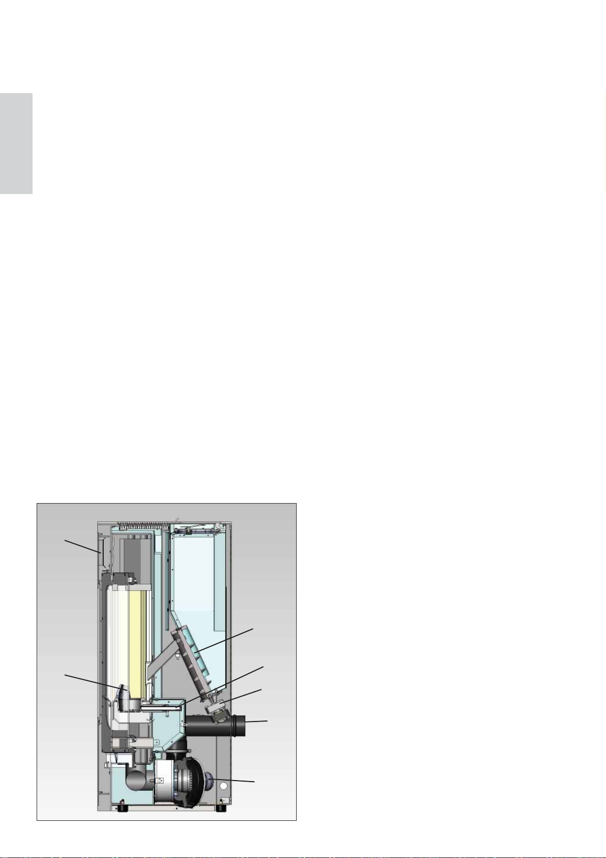
La stufa produce aria calda utilizzando come combustibile il
pellet di legno, la cui combustione è gestita elettronicamente.
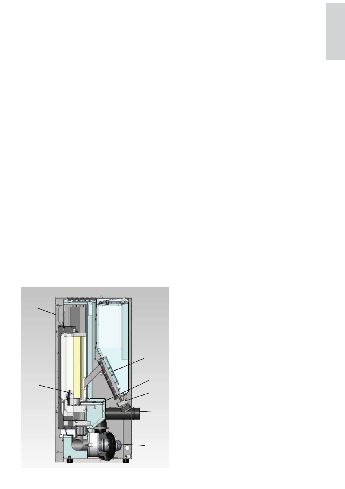
Di seguito ne è illustrato il funzionamento (le lettere fanno
riferimento alla fi gura 1).
Il combustibile (pellet) prelevato dal serbatoio di stoccaggio
(A) tramite una coclea (B) attivata da motoriduttore (C), viene
trasportato nel crogiolo di combustione (D).
L’accensione del pellet avviene tramite aria calda prodotta
da una resistenza elettrica (E) e aspirata nel crogiolo tramite
l’estrattore fumi (F).
I fumi prodotti dalla combustione, vengono estratti dal focolare
tramite lo stesso estrattore (F), ed espulsi dal bocchettone (G)
ubicato nella zona bassa del retro della stufa.
Il focolare (realizzato in Vermiculite) è chiuso frontalmente
da due antine sovrapposte:
- una esterna in vetro ceramico (per l’apertura utilizzare l’apposito guanto in dotazione).
- una interna in vetro ceramico a contatto con il fuoco (per
l’apertura utilizzare l’apposita maniglia “manofredda”).
La quantità di combustibile e l’estrazione fumi/alimentazione
aria comburente, sono regolate tramite scheda elettronica dotata
di software con sistema Leonardo®, al fi ne di ottenere una com-
bustione ad alto rendimento e basse emissioni.
Tutte le fasi di funzionamento sono gestite tramite radiocomando fornito in dotazione.
La stufa è dotata di una presa seriale per collegamento, con cavetto optional (cod. 640560), a dispositivi di accensione remota
(quali combinatori telefonici, cronotermostati ect.).
I
A
B
E
D
C
G
F
fi g. 1
INFORMAZIONI PER LA SICUREZZA
La stufa LOU è progettata per scaldare, attraverso una combustione automatica di pellet nel focolare, il locale nel quale si
trova sia, per irraggiamento che per movimento di aria che esce
dalla griglia frontale (I).
• L’apparecchio non è destinato a essere usato da persone,
bambini compresi, le cui capacità fi siche, sensoriali o mentali,
siano ridotte. I bambini devono essere sorvegliati per sincerarsi
che non giochino con l’apparecchio.
• I principali rischi derivabili dall’impiego della stufa possono
essere legati a una non corretta installazione, a un diretto contatto con parti elettriche in tensione (interne), a un contatto con
fuoco e parti calde (vetro, tubi, uscita aria calda), all’introduzione di sostanze estranee, a combustibili non raccomandati, a
una non corretta manutenzione o ripetuto azionamento del tasto
di accensione senza aver svuotato il crogiolo.
• Nel caso di mancato funzionamento di componenti o anomalie, la stufa è dotata di dispositivi di sicurezza che ne
garantiscono lo spegnimento, il cui intervento non deve essere
ostacolato.
• Per un regolare funzionamento la stufa deve essere installata
rispettando quanto indicato su questa scheda.
• Durante il funzionamento non deve essere aperta la porta del
focolare: la combustione è infatti gestita automaticamente e
non necessita di alcun intervento.
• Usare come combustibile solo pellet di legno diam. 6 mm di
ottima qualità e certifi cato
• In nessun caso devono essere introdotte nel focolare o nel
serbatoio sostanze estranee, rispetto al pellet.
• Per la pulizia del canale da fumo (tratto di canna che collega
il bocchettone di uscita fumi della stufa con la canna fumaria)
non devono essere utilizzati prodotti infi ammabili.
• Le parti del focolare e del serbatoio devono essere solo aspirate e solo a FREDDO.
• Il vetro può essere pulito a FREDDO con apposito prodotto
(es. GlassKamin Edilkamin) e un panno.
• Evitare di aprire il portello della camera di combustione a stufa calda, ma aspettare che il prodotto si raffreddi naturalmente.
• La stufa non deve funzionare con l’antina aperta, con il vetro
rotto o con il portello caricamento pellet aperto.
•Non deve essere utilizzata come scala o come base di appoggio.
• Non appoggiare biancheria direttamente sulla stufa per
asciugare. Eventuali stendibiancheria o simili devono essere
collocati dalla stufa ad una distanza di sicurezza (pericolo di
incendio).
• Assicurarsi che la stufa venga installata e accesa da CAT abilitato Edilkamin (centro assistenza tecnica) secondo le indicazioni della presente scheda; condizioni peraltro indispensabili
per la validazione della garanzia.
• Durante il funzionamento della stufa, i tubi di scarico e la
porta raggiungono alte temperature (non toccare senza l’apposito guanto).
• Non depositare oggetti non resistenti al calore nelle immediate vicinanze della stufa.
• Non usare MAI combustibili liquidi per accendere la stufa o
ravvivare la brace.
• Non occludere le aperture di aerazione nel locale di installazione, né gli ingressi di aria della stufa stessa.
• Non bagnare la stufa, non avvicinarsi alle parti elettriche con
le mani bagnate.
• Non inserire riduzioni sui tubi di scarico fumi.
• La stufa deve essere installata in locali adeguati alla prevenzione antincendio e dotati di tutti i servizi (alimentazione e
scarichi) che l’apparecchio richiede per un corretto e sicuro
funzionamento.
• IN CASO DI FALLITA ACCENSIONE, NON RIPETERE L’ACCENSIONE PRIMA DI AVERE SVUOTATO IL
CROGIOLO.
- 3 -
ITALIANO
ITALIANO
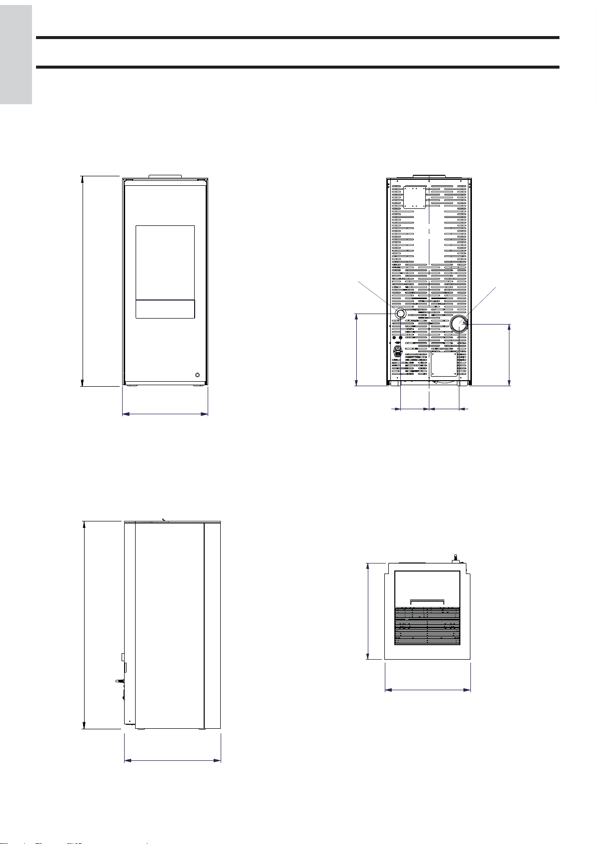
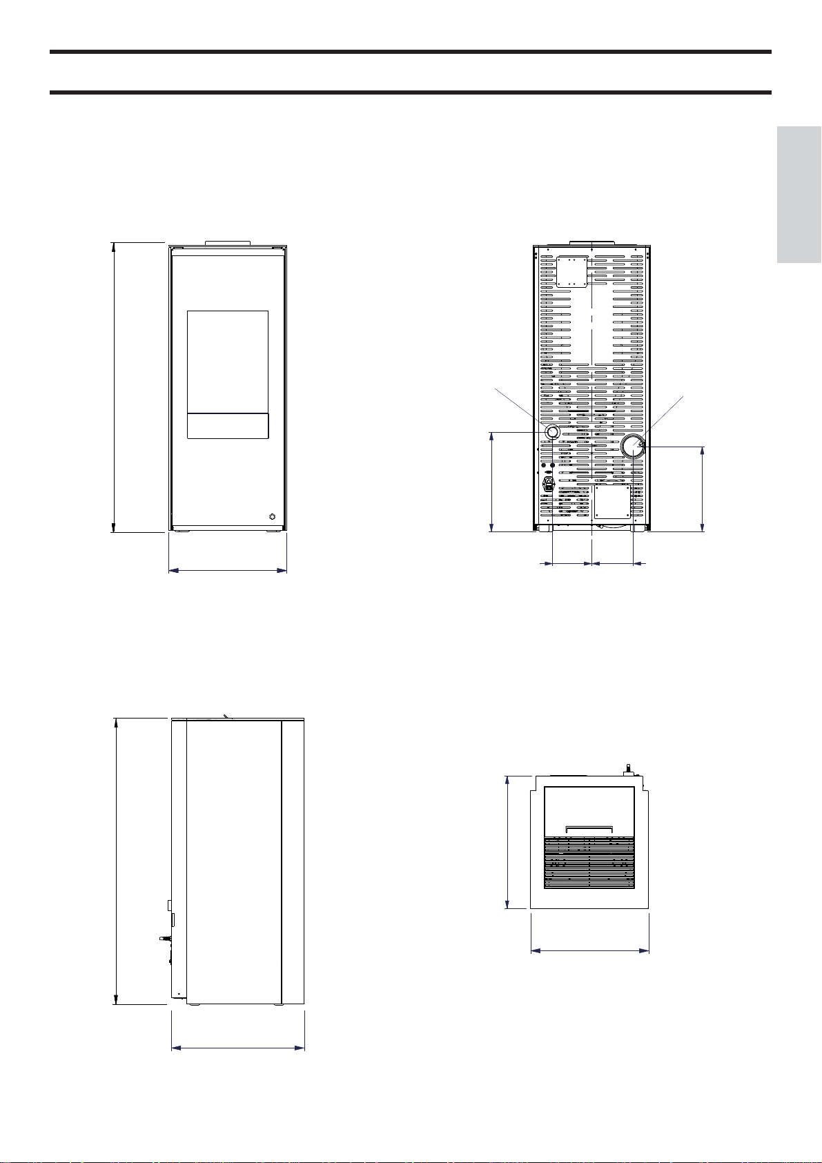
DIMENSIONI
FRONTE RETRO
Ø 4 cm aria
combustione
112
Ø 8 cm uscita fumi
FIANCO
112
46
46
39
PIANTA
52
33
15 16
52
46
- 4 -
CARATTERISTICHE
• APPARATI ELETTRONICI
LEONARDO® è un sistema di sicurezza e regolazione della combustione che consente un funzionamento ottimale in qualunque condizione, grazie a due sensori che rilevano il livello di pressione nella camera
di combustione e la temperatura dei fumi.
La rilevazione e la conseguente ottimizzazione dei due parametri avviene in continuo, in modo da
correggere in tempo reale eventuali anomalie di funzionamento. Il sistema ottiene una combustione
costante regolando automaticamente il tiraggio in base alle caratteristiche della canna fumaria (curve,
lunghezza, forma, diametro ecc.) ed alle condizioni ambientali (vento, umidità, pressione atmosferica,
installazioni in alta quota ecc.).
LEONARDO® è inoltre in grado di riconoscere il tipo di pellet e regolarne automaticamente l’affl usso
per garantire attimo dopo attimo il livello di combustione richiesto.
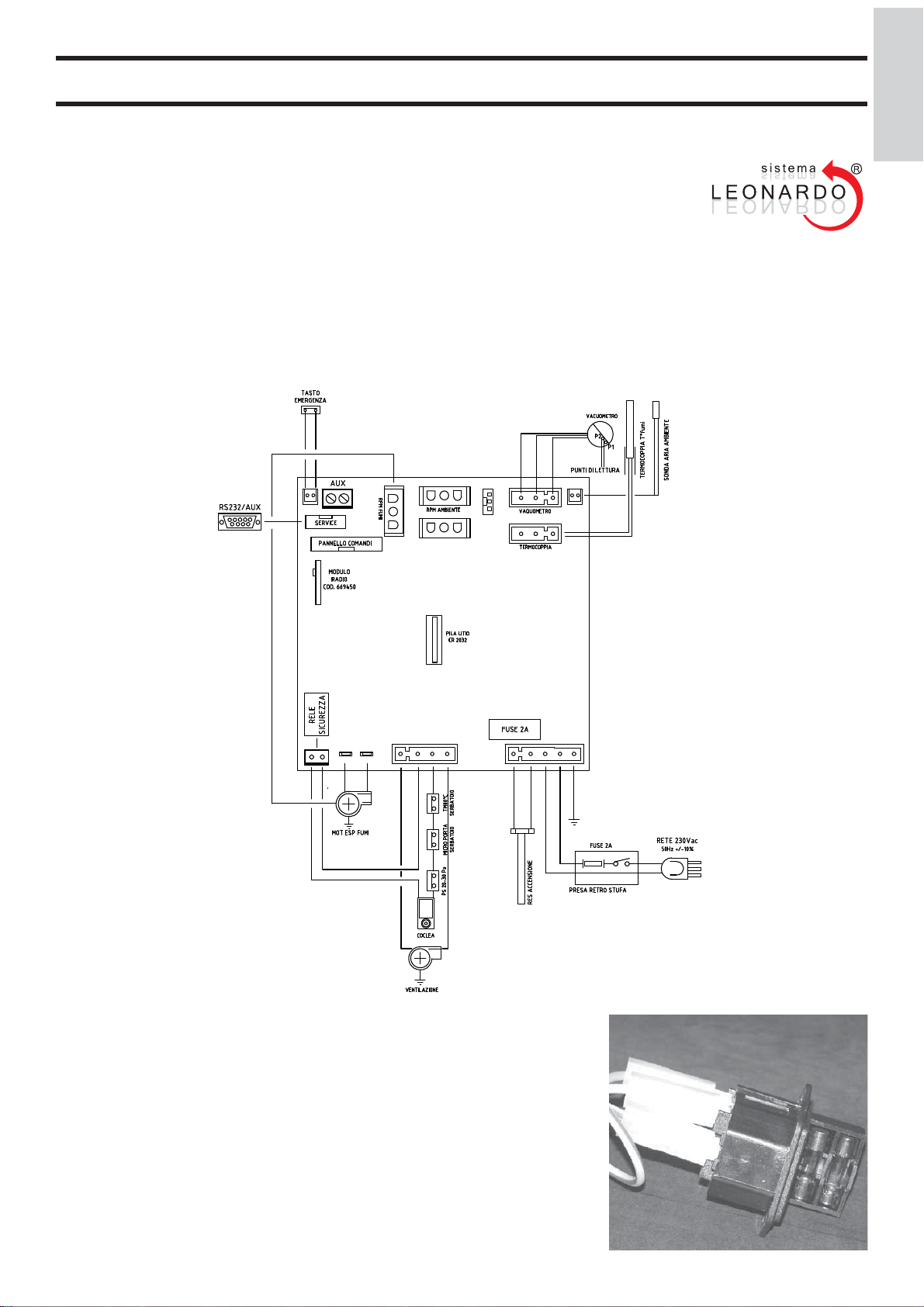
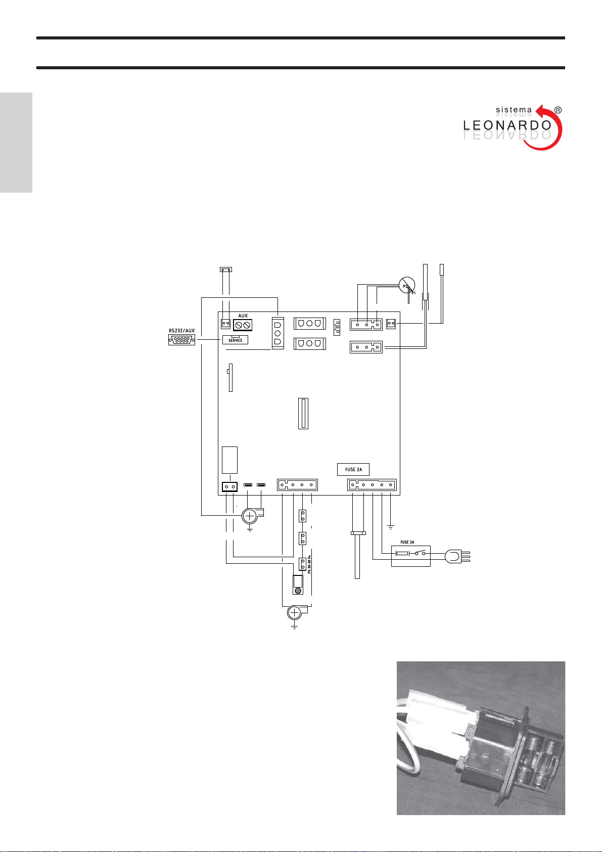
• SCHEDA ELETTRONICA
+
ITALIANO
PORTA SERIALE
Sull’uscita seriale RS232 con apposito cavetto (cod. 640560) è possibile far installare
dal CAT un optional per il controllo delle accensioni e spegnimenti, es. combinatore
telefonico, termostato ambiente.
BA TTERIA T AMPONE
Sulla scheda elettronica è presente una batteria tampone (tipo CR 2032 da 3 Volt).
Il suo malfunzionamento (non considerabile difetto di prodotto, ma normale usura)
viene indicato con scritte “Control. Batteria”.
Per maggiori riferimenti, contattare il CAT che ha effettuato la 1° accensione.
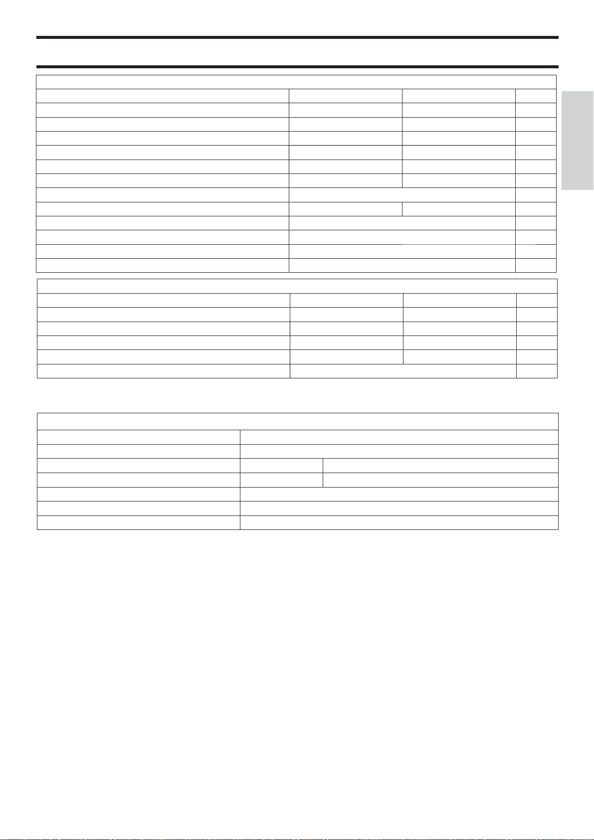
FUSIBILE
sulla presa con interruttore posta sul retro della stufa, sono inseriti due fusibili, di cui
uno funzionale * e l’altro di scorta**.
- 5 -
*
*
*
CARATTERISTICHE
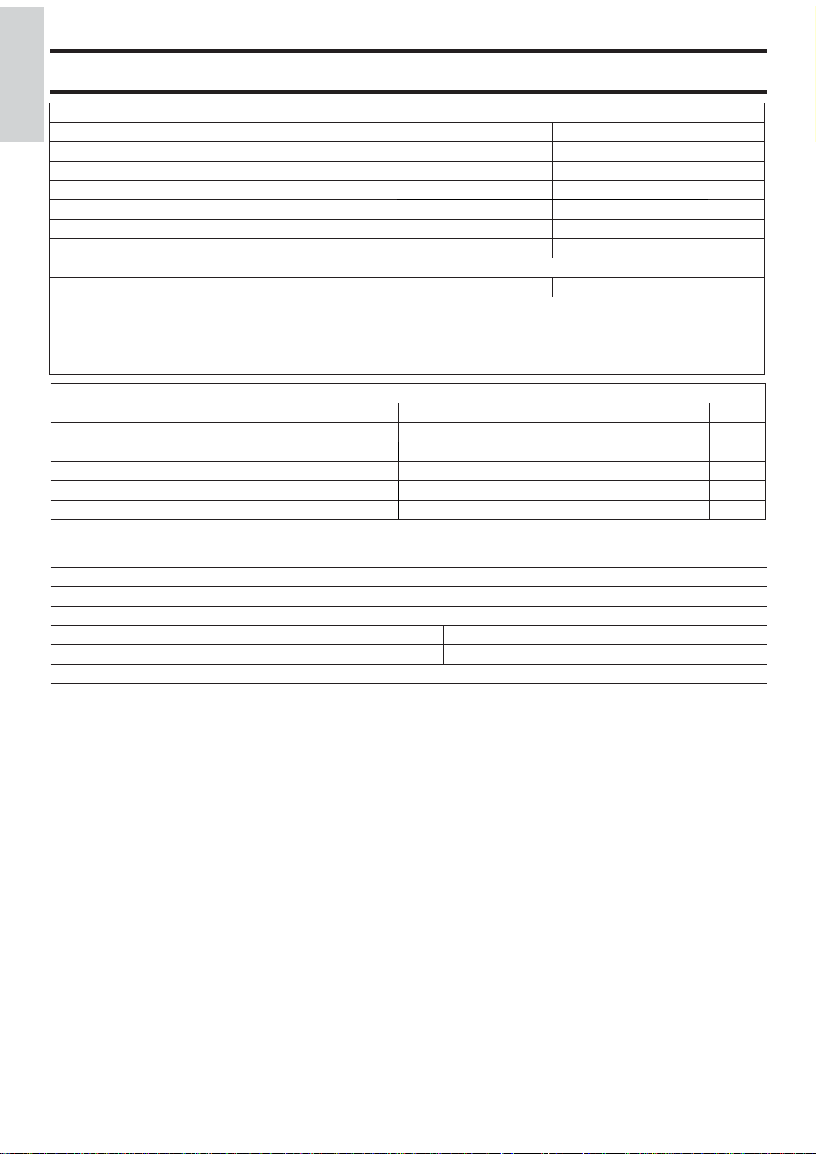
CARATTERISTICHE TERMOTECNICHE ai sensi EN 14785
ITALIANO
Portata termica bruciata 9 2,5 kW
Potenza termica 8 2,4 kW
Rendimento / Effi cienza 93 95,1 %
Emissione CO al 13% O
Temperatura fumi 129 63 °C
Consumo combustibile 1,9 0,5 kg/h
Capacità serbatoio 24 kg
Autonomia 11 42 ore
Volume riscaldabile * 210 m
Diametro condotto fumi (maschio) 80 mm
Diametro condotto presa aria (maschio) 40 mm
Peso con imballo 200 kg
2
DATI TECNICI PER DIMENSIONAMENTO CANNA FUMARIA
Potenza termica 8 2,4 kW
Temperatura uscita fumi allo scarico 200 110 °C
Tiraggio minimo 12 10 Pa
Portata fumi 5,8 3,2 g/s
Classifi cazione focolare secondo DIBt FB 22 FC
* Il volume riscaldabile è calcolato considerando un isolamento della casa come da L 10/91 e successive modifi che e una richiesta
di calore di 33 Kcal/m³ ora.
Potenza Nominale Potenza Ridotta
0,013 0,059 %
Potenza Nominale Potenza Ridotta
52x
3
-
CARATTERISTICHE ELETTRICHE
Alimentazione 230Vac +/- 10% 50 Hz
Interruttore on/off si
Potenza assorbita media 100 W
Potenza assorbita in accensione 400 W
Frequenza radiocomando (fornito) onderadio 2,4 GHz
Protezione su alimentazione generale * (vedi pag. 5) Fusibile T2A, 250 Vac 5x20
Protezione su scheda elettronica * Fusibile T2A, 250 Vac 5x20
N.B.
1) tenere in considerazione che apparecchiature esterne possono provocare disturbi al funzionamento della scheda elettronica.
2) attenzione: interventi su componenti in tensione, manutenzioni e/o verifi che devono essere fatte da personale qualifi cato.
(prima di effettuare qualsiasi manutenzione, disinserire l’apparecchio dalla rete di alimentazione elettrica)
I dati sopra riportati sono indicativi e rilevati in fase di certifi cazione presso organismo notifi cato.
EDILKAMIN s.p.a. si riserva di modifi care i prodotti senza preavviso e a suo insindacabile giudizio.
DISPOSITIVI di SICUREZZA
• TERMOCOPPIA:
posta sullo scarico fumi ne rileva la temperatura. In funzione dei parametri impostati controlla le fasi di accensione, lavoro e spegnimento.
• VACUOMETRO:
Posto sull’estrattore fumi, rileva il valore della depressione (rispetto all’ambiente di installazione) in camera di combustione.
• TERMOSTATO DI SICUREZZA:
Interviene nel caso in cui la temperatura all’interno della stufa è troppo elevata.
Blocca il caricamento del pellet provocando lo spegnimento della stufa.
• PRESSOSTATO SICUREZZA:
Interviene nel caso in cui la depressione all’interno della camera di combustione sia insuffi cente per il corretto funzionamento.
- 6 -
INSTALLAZIONE
Tutte le leggi locali e nazionali e le Norme Europee devono
essere soddisfatte nell’installazione e nell’uso dell’apparecchio.
In Italia fare riferimento alla norma UNI 10683/2012, nonché
ad eventuali indicazioni regionali o delle ASL locali.
In Francia fare riferimento Decreto 2008-1231 art. R131-2.
E’ indispensabile comunque fare riferimento alle leggi vigenti
nelle singole nazioni. In caso di installazione in condominio,
chiedere parere preventivo all’amministratore.
VERIFICA DI COMPATIBILITA’ CON AL TRI
DISPOSITIVI
In Italia la stufa NON deve essere installata nello stesso ambiente in cui si trovano apparecchi da riscaldamento a gas del
tipo B (es. caldaie a gas, stufe e apparecchi asserviti da cappa
aspirante) in quanto la stufa potrebbe mettere in depressione
l’ambiente compromettendo il funzionamento di tali apparecchi
oppure esserne infl uenzata. Ai sensi della norma UNI 10683 la
stufa può essere installata anche in camera da letto.
VERIFICA ALLACCIAMENTO ELETTRICO (posizionare la presa di corrente in un punto facilmente accessibile)
La stufa è fornita di un cavo di alimentazione elettrica da
collegarsi ad una presa di 230V 50 Hz, preferibilmente con
interruttore magnetotermico. Variazioni di tensione superiori
al 10% possono compromettere il funzionamento della stufa.
L’impianto elettrico deve essere a norma; verifi care in parti-
colare l’effi cienza del circuito di terra. La non effi cienza del
circuito di terra provoca mal funzionamento di cui Edilkamin
non si può far carico. La linea di alimentazione deve essere di
sezione adeguata alla potenza dell’apparecchiatura.
POSIZIONAMENTO
Per il corretto funzionamento la stufa deve essere posizionata
in bolla.Verifi care la capacità portante del pavimento.
DISTANZE DI SICUREZZA ANTICENDIO
La stufa deve essere installata nel rispetto delle seguenti condizioni di sicurezza:
- distanza minima sui lati e sul retro di 20 cm dai materiali
infi ammabili.
- davanti alla stufa non possono essere collocati materiali
infi ammabili a meno di 80 cm.
Se non risultasse possibile rispettare le distanze sopra indicate,
è necessario mettere in atto provvedimenti tecnici ed edili
per evitare ogni rischio di incendio. In caso di collegamento
con parete in legno o altro materiale infi ammabile, è necessario
coibentare adeguatamente il tubo di scarico fumi.
SCARICO FUMI
Il sistema di scarico deve essere unico per la stufa (non si
ammettono scarichi in canna fumaria comune con altri
dispositivi)
In Germania lo scarico può avvenire in canna multipla con
esplicita verifi ca di uno spazzacamino.
Lo scarico dei fumi avviene dal bocchettone di diametro 8 cm
posto sul retro.
Lo scarico fumi deve essere collegato con l’esterno utilizzando
tubi in acciaio certifi cati EN 1856. Il tubo deve essere sigil-
lato ermeticamente. Per la tenuta dei tubi e il loro eventuale
isolamento è necessario utilizzare materiali resistenti alle alte
temperature (silicone o mastici per alte temperature).
L’unico tratto orizzontale ammeso può avere lunghezza fi no a
2 m. E’ possibile un numero di curve con ampiezza max. 90°
(rispetto alla verticale) fi no a tre.
E’ necessario (se lo scarico non si inserisce in una canna fumaria) un tratto verticale di almeno 1,5 mt e un terminale antivento (riferimento UNI 10683/2012).
In Francia fare riferimento per lo scarico dei fumi al DTU 24.1
e DTU 24.2.
Il condotto verticale può essere interno o esterno.
Se il canale da fumo è all’esterno deve essere coibentato
adeguatamente. Se il canale da fumo si inserisce in una canna
fumaria, questa deve essere idonea per combustibili solidi.
Se la canna fumaria esistente è più grande di ø 150 mm, è
necessario risanarla intubandola con tubi di sezione e materiali
idonei (es. acciaio ø 80 mm).
Tutti i tratti del condotto fumi devono essere ispezionabili.
I comignoli e condotti di fumo ai quali sono collegati gli apparecchi utilizzatori di combustibili solidi devono venire puliti
almeno una volta all’anno (verifi care se nella propria nazione
esiste una normativa al riguardo).
L’assenza di controllo e pulizia regolari aumenta la probabilità
di incendio del comignolo. Nel caso procedere come segue:
non spegnere con acqua; svuotare il serbatoio del pellet.
Rivolgersi a personale specializzato prima di riavviare la macchina.
La stufa è progettata per funzionare con qualsiasi condizione
climatica. Nel caso di particolari condizioni, come vento forte,
potrebbero intervenire sistemi di sicurezza che portano in
spegnimento la stufa. In questo caso non far funzionare l’apparecchio con le sicurezze disabilitate, se il problema dovesse
persistere contattare il Centro Assistenza Tecnica autorizzato
Edilkamin.
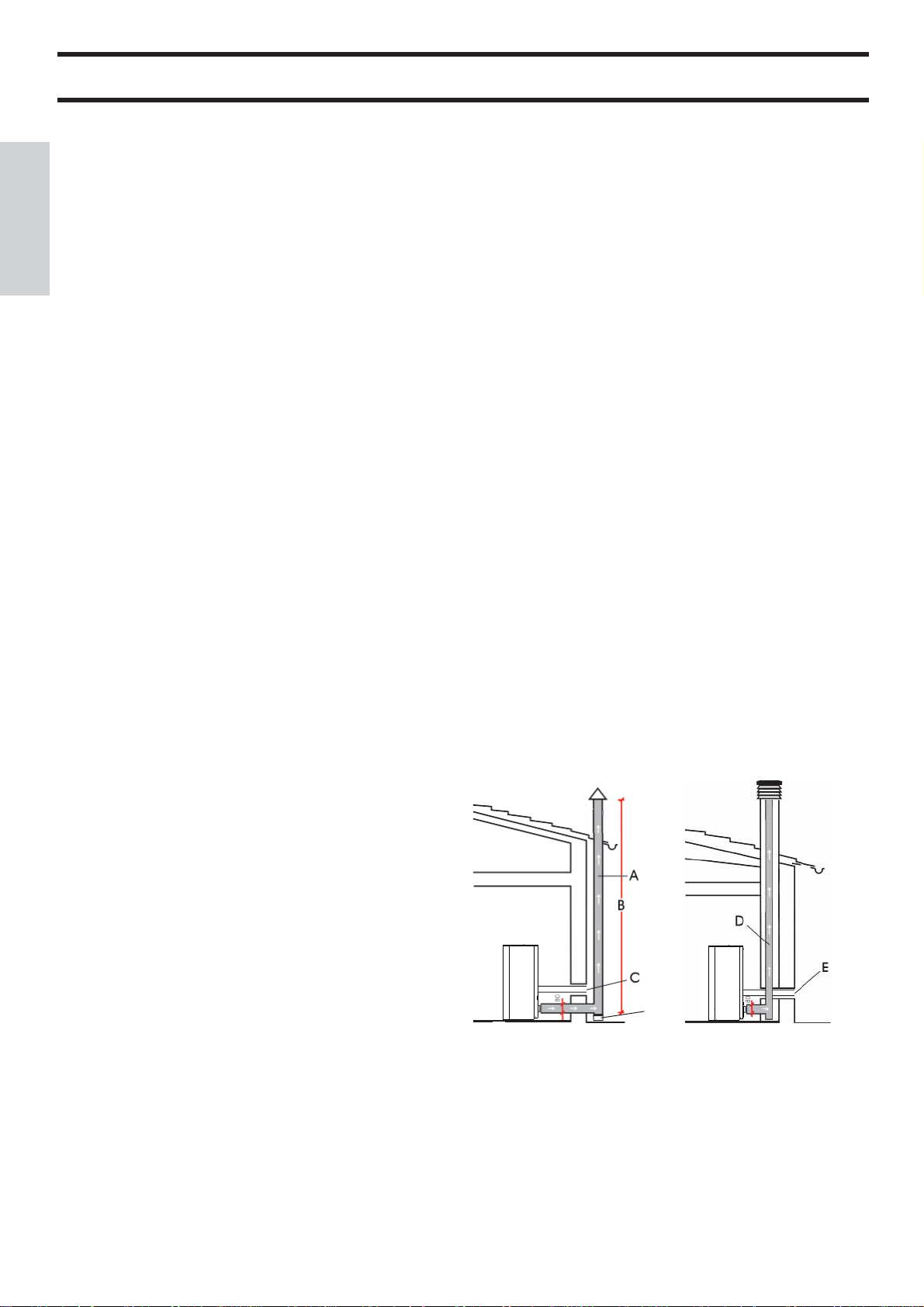
CASI TIPICI
Fig. 1 Fig. 2
ITALIANO
PRESA D’ARIA
La stufa è adatta per l’installazione anche in case defi nite
“passive”. In questo caso è indispensabile prelevare l’aria per
la combustione collegando (in modo ermetico) con l’esterno il
bocchettone presente sul retro della stufa stessa tramite un tubo
ø 4 cm.
Accertarsi che la presa d’aria esterna venga posizionata in
maniera tale da non poter venire ostruita.
In Francia fare riferimento Decreto 2008-1231 art. R131-2
permetto installazioni di cui sopra.
In tutti gli altri tipi di case la stufa può essere installata in
modo tradizionale e quindi anche con utilizzo di aria ambiente
(rispettare comunque le norme tecniche di riferimento).
Il tubo deve essere di lunghezza inferiore a 1 metro e non deve
presentare curve. In ogni caso lungo tutto il percorso del condotto presa aria deve essere garantita una sezione libera almeno
di 12 cm². Il terminale esterno del condotto presa aria deve
terminare con un tratto a 90° gradi verso il basso o con una
protezione antivento ed essere protetto con una rete anti insetti
che comunque non riduca la sezione passante utile di 12 cm².
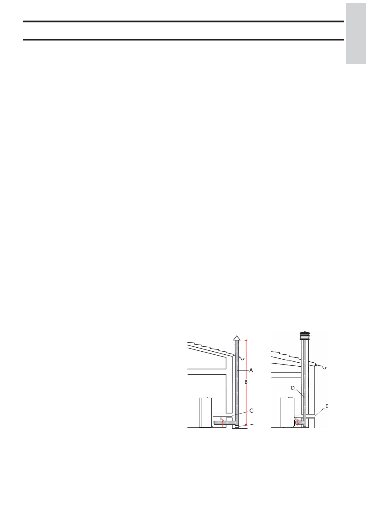
ispezione
A: canna fumaria in acciaio coibentata
B: altezza minima 1,5 m e comunque oltre la quota di gronda del tetto
C-E: presa d’aria dall’ambiente esterno (sezione passante minimo 80 cm²)
D: canna fumaria in acciaio, interna alla canna fumaria esistente in muratura
COMIGNOLO
Le caratteristiche fondamentali sono:
- sezione interna alla base uguale a quella della canna fumaria
- sezione di uscita non minore del doppio di quella della canna fumaria
- posizione al di sopra del colmo tetto ed al di fuori delle zone
di refl usso ( vedi norma UNI 10683/12).
- 7 -
ISTRUZIONI D’USO
La messa in servizio, la prima accensione ed il collaudo devono
ITALIANO
essere eseguiti da un centro assistenza autorizzato Edilkamin
(CAT) nel rispetto della norma UNI 10683/2012.
Detta norma indica le operazioni di controllo da eseguire al fi ne
di accertare il corretto funzionamento del sistema.
B
Il CAT provvederà anche a tarare la stufa in base al tipo di pellet e alle condizioni di installazione attivando così la garanzia.
La mancata prima accensione da parte di un C.A.T. autorizzato
Edilkamin non consente l’attivazione della garanzia.
Per informazioni consultare il sito www.edilkamin.com
Durante le prime accensioni si possono sviluppare leggeri odori
di vernice che scompariranno in breve tempo.
Prima di accendere è comunque necessario verifi care:
• La corretta installazione.
• L’alimentazione elettrica.
• La chiusura della porta, che deve essere a tenuta ermetica
• La pulizia del crogiolo.
• La presenza sul display dell’indicazione di stand-by
(data, potenza o temperatura lampeggianti).
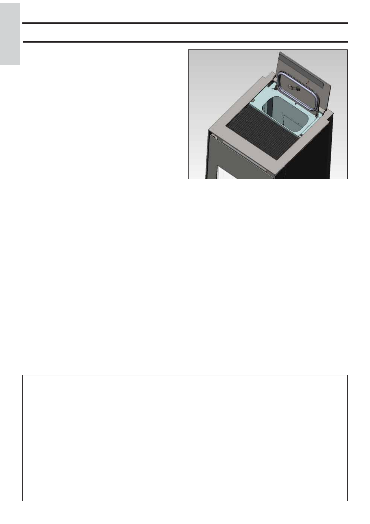
CARICAMENTO DEL PELLET NEL SERBATOIO
Per accedere al serbatoio aprire i due portelli sulla parte
posteriore del top (A e B - fi g. 1).
N.B.:
1) Durante questa operazione NON APPOGGIARE
MAI il sacchetto di pellet sulla griglia superiore, evitando
così che il sacchetto di plastica con il calore possa
rovinare la vernice del top.
2) Utilizzare apposito guanto in dotazione se si carica la
stufa mentre è in funzione e quindi calda.
3) E’ consigliato il caricamento del pellet nel serbatoio entro
40 secondi dall’apertura del serbatoio stesso.
A
fi g. 1
NOTA sul combustibile.
LOU è progettata e programmata per bruciare pellet di legno
di diametro di 6 mm circa.
Il pellet è un combustibile che si presenta in forma di piccoli
cilindretti, ottenuti pressando segatura, ad alti valori, senza
uso di collanti o altri materiali estranei.
E’ commercializzato in sacchetti da 15 Kg.
Per NON compromettere il funzionamento della termostufa è
indispensabile NON bruciarvi altro.
L’impiego di altri materiali (legna compresa), rilevabile da
analisi di laboratorio, implica la decadenza della garanzia.
Edilkamin ha progettato, testato e programmato i propri prodotti perché garantiscano le migliori prestazioni con pellet
delle seguenti caratteristiche:
diametro : 6 millimetri
lunghezza massima : 40 mm
umidità massima : 8 %
resa calorica : 4300 kcal/kg almeno
L’uso di pellet con diverse caratteristiche implica la necessità
di una specifi ca taratura della termostufa, analoga a quella che
fa il CAT (centro assistenza tecnica) alla 1° accensione.
L’uso di pellet non idonei può provocare: diminuzione del rendimento; anomalie di funzionamento; blocchi per intasamento,
sporcamento del vetro, incombusti, …
Una semplice analisi del pellet può essere condotta visivamente:
Buono: liscio, lunghezza regolare, poco polveroso.
Scadente: con spaccature longitudinali e trasversali, molto
polveroso, lunghezza molto variabile e con presenza di corpi
estranei.
- 8 -
ISTRUZIONI D’USO
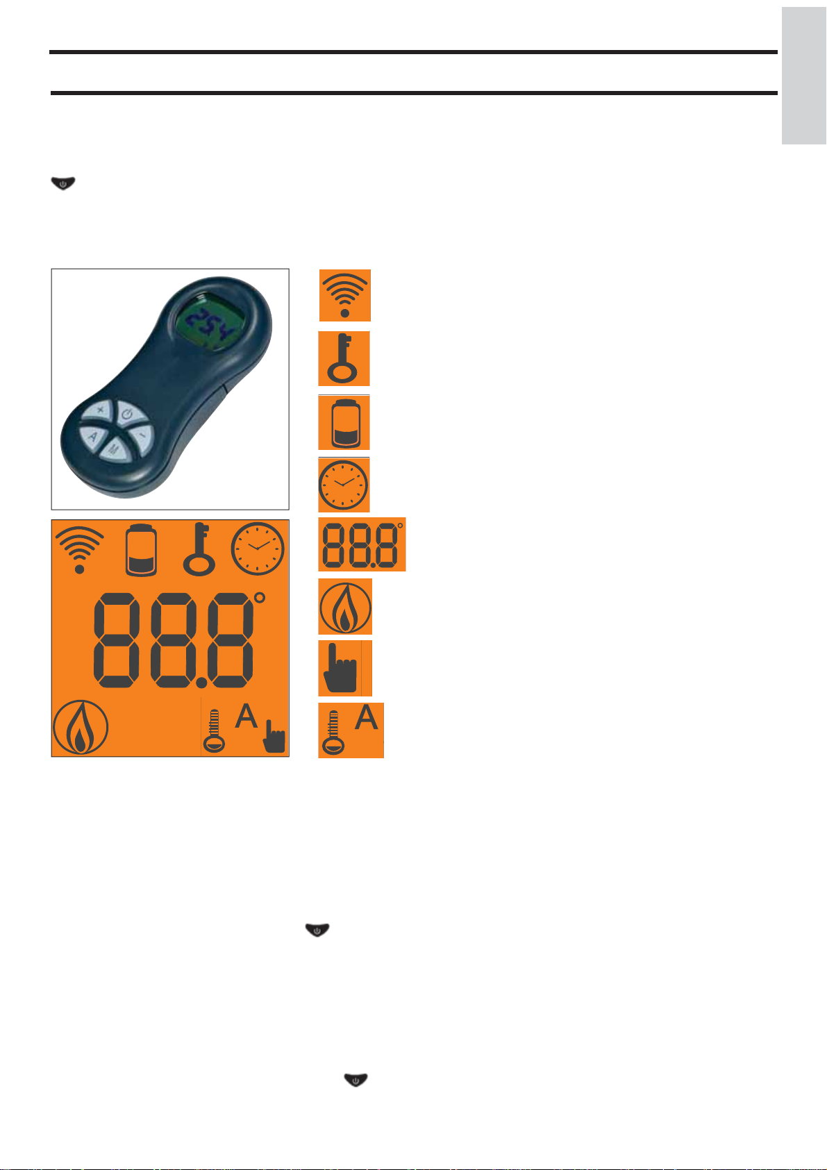
RADIOCOMANDO
Serve per gestire tutte le funzioni per l’utilizzo.
Legenda tasti e display:
: per accendere e spegnere (per passare da radiocomando stand by a radiocomando attivo)
+/- : per incrementare / decrementare le diverse regolazioni
A : per selezionare il funzionamento Automatico
M :
per selezionare il funzionamento Manuale e per accedere ai menù di controllo e programmazione
- icona lampeggiante: radiocomando in ricerca di rete
- icona fi ssa: radiocomando con collegamento attivo
tastiera bloccata (premere “A” e “M” in contemporanea per
qualche secondo per bloccare o sbloccare la tastiera)
batteria scarica (n°3 pile alkaline mini stilo AAA)
programmazione attivata
ITALIANO
display alfanumerico composta da 16 cifre disposte in due righe
da 8 cifre ciascuna
- icona lampeggiante: stufa in fase di accensione
- icona fi ssa: stufa in fase di lavoro
funzione di regolazione manuale (appare sul display il valore
della potenza di lavoro)
funzione automatica
(appare sul display il valore della temperatura)
Sul display si visualizzano altre informazioni utili, oltre alle icone descritte sopra.
- Posizione Stand-by:
si visualizza la temperatura ambiente (20°C), i Kg di pellet rimasti (15Kg) nel serbatoio e l’ora corrente (15:33)
- Fase di lavoro manuale:
si visualizza la potenza impostata (Power 1), la temperatura ambiente (20°C), i Kg di pellet e l’autonomia residua (15Kg 21H)
- Fase di lavoro automatica:
si visualizza la temperatura impostata (Set 22°C), la temperatura ambiente (20°C), i Kg di pellet e l’autonomia residua (15Kg
21H).
NON PREMERE PIU’ VOLTE IL TASTO .
N.B.: Se il radiocomando non viene utilizzato per alcuni secondi, il display si oscura, perchè viene attivata la funzione di risparmio energetico. Il display si riattiva premendo un tasto qualsiasi.
Disattivazione ventilazione
Per disattivare/riattivare la ventilazione della stufa procedere come segue: premere per 2” il tasto M, premere 2 volte il tasto +, si
visualizza a display “COMFORT AIR”, comfermare tale visualizzazione con il tasto M, si accede così al menù di selezione ventilazione. Con i tasti +/- si passa alternativamente dalla visualizzazione COMFORT AIR (ventilazione attiva) alla visualizzazione
“AIR OFF” (ventilazione disattiva), premere il tasto per salvare l’impostazione.
- 9 -

ISTRUZIONI D’USO
Riempimento coclea.
ITALIANO
Al primo utilizzo o in caso di svuotamento completo del serbatoio del pellet, per riempire la coclea premere contemporaneamente i tasti “+” e “–” dal radiocomando, per qualche secondo;
dopo di che, lasciati i tasti, a display compare la scritta “RICARICA”.
L’operazione è da eseguirsi prima dell’accensione se la stufa si
è fermata per esaurimento pellet, a fi ne operazione svuotare il
crogiolo prima di accendere.
E’ normale che nel serbatoio resti una quantità residua di pellet
che la coclea non riesce caricare il pellet.
Accensione automatica
A stufa in stand by, premendo per 2” il tasto
mando, si avvia la procedura di accensione e viene visualizzata
la scritta “Avvio”, contemporaneamente ha inizio un conto alla
rovescia in secondi (da 1020 a 0). La fase di accensione non
è tuttavia a tempo predeterminato: la sua durata è automaticamente abbreviata se la scheda rileva il superamento di alcuni
test. Dopo circa 5 minuti compare la fi amma.
Accensione manuale
In casi di temperatura sotto i 3°C che non permetta alla resistenza elettrica di arroventarsi a suffi cienza o di temporanea
non funzionalità della resistenza stessa, è possibile usare per
l’accensione della “diavolina”.
Introdurre nel crogiolo un pezzetto di “diavolina” ben accesa,
chiudere la porta e premere dal radiocomando.
REGOLAZIONE POTENZA
• Funzionamento manuale da radiocomando
A stufa in funzione, premendo una volta il tasto “M” sul radiocomando viene visualizzata a display la scritta “POTENZA P”
(con indicazione della potenza in cui la stufa sta lavorando),
premendo i tasti “+” o “–” è possibile incrementare o decrementare la potenza di lavoro della stufa (da “POTENZA P1” a
“POTENZA P5” ).
• Funzionamento automatico da radiocomando
Premendo il tasto “A” si commuta a funzionamento automatico
regolando la temperatura che si vuole raggiungere nel locale
(per impostare la temperatura da 5°C a 35°C utilizzare i tasti
“+” e “–” e la stufa regola la potenza di lavoro per raggiungere
la temperatura impostata. Se si imposta una temperatura inferiore a quella del locale, la stufa rimarrà in “POTENZA P1”.
Spegnimento
A stufa funzionante premendo per 2” il tasto dal radiocomando si avvia la procedura di spegnimento sul display viene
visualizzato il conto alla rovescia da 9 a 0 (per un totale di 10
minuti).
La fase di spegnimento prevede:
• Interruzione caduta pellet.
• Ventilazione al massimo.
• Motore espulsione fumi al massimo.
Non staccare mai la spina durante la fase di spegnimento.
, sul radioco-
OPERAZIONI EFFETTUABILI SOLO CON RADIOCOMANDO
Regolazione orologio
Premendo per 2” il tasto “M” si accede al Menù “Orologio”
che consente di impostare l’orologio interno alla scheda elettronica.
Premendo successivamente il tasto “M”, appaiono in sequenza
e possono essere regolati i seguenti dati:
Giorno, Mese, Anno, Ora, Minuti, Giorno della settimana.
La scritta SALVO DATI?? da confermare con “M” permette
di verifi care l’esattezza delle operazioni compiute prima di
confermarle (viene allora visualizzato sul display la scritta
Salvataggio).
Le operazioni di accensione, spegnimento, regolazione potenza
possono essere eseguite tramite il pulsante di emergenza rosso,
posizionato sul retro della stufa (vedi pag. 11).
Programmatore orario settimanale
Premendo per 2 secondi il tasto “M” dal radiocomando si
accede alla regolazione dell’orologio e premendo il tasto “+”
si accede alla funzione di programmazione oraria settimanale,
identifi cata sul display con la descrizione “PROGRAM. ON/
OFF”.
Questa funzione permette di selezionare il tipo di programmazione nelle quali è possibile impostare fi no ad un massimo di
tre accensioni.
Confermando a display col tasto “M” appare una delle seguenti
possibilità:
NO PROG ( nessun programma impostato)
PROGRAMMA GIORNAL. (unico programma per tutti i
giorni)
PROGRAM. SETT.NA (programma specifi co per ogni singolo
giorno)
Con tasti “+” e “–” si passa da un tipo di programmazione
all’atro.
Confermando col tasto “M” l’opzione “PROGRAMMA GIORNAL.” e premendo il tasto “+” si accede alla scelta del numero
di programmi (accensioni/spegnimenti) eseguibili in un giorno.
Utilizzando “PROGRAMMA GIORNAL.” il programma/i
impostato/i sarà lo stesso per tutti i giorni della settimana.
Premendo successivamente il tasto “+” si possono visualizzare:
- NO PROG.
- 1° progr. (una accensione e uno spegnimento al giorno), 2°
progr. (idem), 3° progr. (idem)
Usare il tasto “–” per visualizzare in ordine inverso.
Se si seleziona 1° programma viene visualizzata l’ora della
accensione.
A display compare: 1 “ACCESO” ore 10; con il tasto “+” e “–”
si varia l’ora e si conferma col tasto “M” (All 1 On/Hour 10).
A display compare: 1 “ACCESO” minuti 30; con il tasto “+” e
“–” si variano i minuti e si conferma col tasto “M” (1 Off min).
Analogamente per il momento dello spegnimento da programmare e per le successive accensioni o spegnimenti
Si conferma premendo “M” all’apparizione della scritta SALVO DATI?? sul display.
Confermando “PROGRAM. SETT.NA” si dovrà scegliere il
giorno nel quale eseguire la programmazione:
7 Do; Progr.1; 1 Lu; 2 Ma; 3 Me; 4 Gi; 5 Ve; 6 Sa;
Una volta selezionato il giorno, utilizzare i tasti “+” e “–” e
confermare col tasto “M” per scegliere da 1 a 3 accensioni, si
proseguirà con la programmazione con la stessa modalità con
la quale si esegue un “PROGRAMMA GIORNAL.”, scegliendo per ogni giorno della settimana se attivare una programmazione stabilendone numero di interventi ed a quali orari.
in caso di errore in qualunque momento della programmazione
si può uscire dal programma senza salvare premendo tasto
, a display comparirà NO SALVATAGGIO.
- 10 -
ISTRUZIONI D’USO
Variazione carico pellet (con autoregolazione disattivata)
Premendo per due secondi il tasto “M” dal radiocomando e
scorrendo le indicazioni del display con i tasti “+” e “–” , si
incontra la descrizione “Menù utente”, poi confermando appare
la scritta “ADJ-PELLET ; ADJ-TIRAGGIO e MENU RADIO”
(CAT).
E’ possibile correggere manualmente la caduta del pellet, variandone la portata in termini percentuali (+/- 30 %).
Confermando questa funzione con il tasto menù si accede ad
una regolazione del caricamento del pellet, diminuendo il valore impostato si diminuisce il caricamento del pellet, incrementando il valore impostato si aumenta il caricamento del pellet.
Questa funzione può essere utile nel caso in cui sia cambiato
il tipo di pellet per il quale è stato tarato la stufa e sia quindi
necessaria una correzione del caricamento.
Se tale correzione non fosse suffi ciente contattare il CAT,
centro assistenza tecnica autorizzato Edilkamin, per stabilire il
nuovo assetto di funzionamento.
Nota sulla variabilità della fi amma: Eventuali variazioni dello
stato della fi amma dipendono dal tipo di pellet impiegato,
nonché da una normale variabilità della fi amma di combusti-
bile solido e dalle pulizie periodiche del crogiolo che la stufa
automaticamente esegue (NB:che NON si sostituiscono alla
necessaria aspirazione a freddo da parte dell’utente prima
dell’accensione).
SEGNALAZIONE RISERVA
La stufa è dotata di funzione elettronica per determinare il
quantitativo di pellet residuo nel serbatoio.
Il sistema, integrato all’interno della scheda elettronica permette di visualizzare in qualsiasi momento quanti Kg mancano
all’esaurimento pellet .
È importante per il corretto funzionamento del sistema che
durante la prima accensione (a cura del CAT) venga eseguito il
seguente procedimento.
Si tratta di un riferimento indicativo. Una maggior precisione si
ottiene con un regolare azzeramento prima del nuovo caricamento.
Edilkamin non risponderà in alcun modo di variazioni rispetto
all’indicato (può dipendere da fattori esterni).
ITALIANO
Kg residui nel serbatoio Kg caricati
quindi con il tasto “+” portare la cifra (*) al valore pari ai Kg di
pellet caricati (15 kg nel caso sopra ipotizzato).
4. premere il tasto “M” per confermare
5. premere il tasto per uscire.
A seguito dell’effettuazione dell’operazione di cui sopra il
sistema dopo il consumo di 15 Kg farà nuovamente apparire
lampeggiando ad intermittenza la scritta “RISERVA”.
Dopo di che dovrà essere ripetuta l’operazione procedendo dal
punto 1 al punto 5.
PULSANTE DI EMERGENZA
Nel caso in cui il radiocomando fosse guasto, è possibile
accedere alle funzioni di base tramite un pulsante di emergenza
rosso, posizionato sul retro della stufa (vedi fi g. 1).
Premere il pulsante una o più volte per attivare la funzione
desiderata:
1. A STUFA SPENTA
premendo il pulsante rosso per 2” si accende.
2. A STUF A ACCESA
premendo il pulsante rosso per 2” si spegne.
3. A STUF A ACCESA
modalità manuale, premendo il pulsante rosso si passa da P1
sino a P3.
4. A STUF A ACCESA
modalità automatica, premendo il pulsante rosso si passa da
5°C a 30°C.
Sistema riserva pellet
Prima di attivare il sistema, è necessario caricare nel serbatoio
un sacchetto di pellet e utilizzare la stufa fi no ad esaurimen-
to del combustibile caricato. Ciò al fi ne di ottenere un breve
rodaggio del sistema.
Dopo di che è possibile riempire completamente il serbatoio e
quindi mettere in funzione la stufa.
Durante il funzionamento, nel momento in cui sarà possibile
caricare un intero sacchetto da 15 Kg di pellet (utilizzare il
guanto in dotazione), apparirà a display, lampeggiando ad
intermittenza, la scritta “RISERVA”.
A questo punto dopo aver versato un sacchetto di pellet, è necessario inserire in memoria l’avvenuto carico dei 15 Kg.
A tal fi ne procedere come segue:
1. premere il tasto “M” (per circa 3-4 secondi) fi no alla com-
parsa della scritta “OROLOGIO”.
2. premere il tasto “+” fi no alla comparsa della scritta “RISER-
VA”.
3. premere il tasto “M” per la comparsa della seguente videata,
pulsante di emergenza
fi g. 1
- 11 -
MANUTENZIONE
Prima di effettuare qualsiasi manutenzione, scollegare l’ap-
ITALIANO
parecchio dalla rete di alimentazione elettrica.
Una regolare manutenzione è alla base del buon funzionamento della stufa
Eventuali problemi dovuti alla mancata manutenzione causeranno la decadenza della garanzia.
MANUTENZIONE GIORNALIERA
Operazioni da eseguire, a stufa spenta, fredda e scollegata
dalla rete elettrica
• L’intera procedura richiede pochi minuti, deve essere effettuata con l’aiuto di un aspirapolvere (vedi optional pag. 16).
• Aprire l’antina, estrarre il crogiolo (1 - fi g. A) e rovesciare i
residui nel cassetto cenere (2 - fi g. B).
• NON SCARICARE I RESIDUI NEL SERBATOIO DEL
PELLET.
• Estrarre e svuotare il cassetto cenere (2 - fi g. B) in un con-
tenitore non infi ammabile (la cenere potrebbe contenere parti
ancora calde e/o braci).
• Aspirare l’interno del focolare, il piano fuoco, il vano attorno
al crogiolo dove cade la cenere.
• Togliere il crogiolo (1 - fi g. A) e scrostarlo con la spatolina in
dotazione, pulire eventuali occlusioni dei fori.
• Aspirare il vano crogiolo, pulire i bordi di contatto del crogiolo con la sua sede.
• Se necessario pulire il vetro (a freddo)
Non aspirare mai la cenere calda, compromette l’aspiratore
impiegato e può creare rischio di incendio
MANUTENZIONE SETTIMANALE
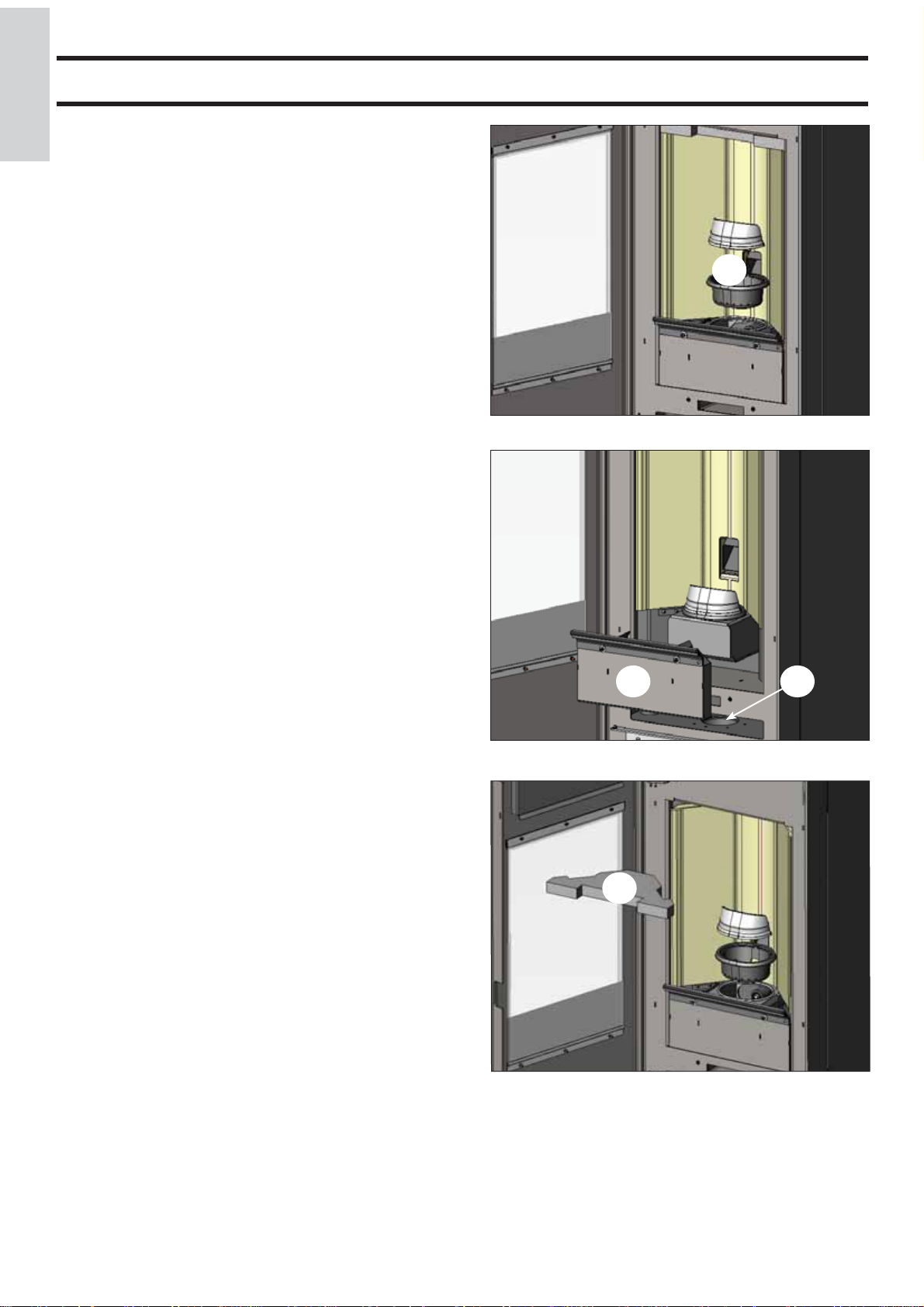
• Estrarre il cielino (3 - fi g. C) e rovesciare i residui nel cassetto
cenere (2 - fi g. B).
Il cielino è un componente soggetto ad usura, Edilkamin non
potrà rispondere di rotture dello stesso, tanto più se la rottura
è dovuta alla movimentazione per l’estrazione o il riposizionamento dello stesso nella sua sede.
• Pulire la camera di combustione e il vano estrattore fumi (4 fi g. B).
fi g. A
fi g. B
3
2
1
4
- 12 -
fi g. C
MANUTENZIONE
MANUTENZIONE STAGIONALE
(a cura del CAT - centro assistenza tecnica)
Consiste nella:
• Pulizia generale interna ed esterna
• Pulizia accurata dei tubi di scambio posti all’interno della
griglia uscita aria calda ubicata nella parte alta del frontale della
stufa
• Pulizia accurata e disincrostazione del crogiolo e del relativo
vano
• Pulizia estrattore fumi, verifi ca meccanica dei giochi e dei
fi ssaggi
• Pulizia canale da fumo (eventuale sostituzione della guarnizione sul tubo scarico fumi)
• Pulizia condotto fumi
• Svuotamento del serbatoio pellet e aspirazione del fondo.
• Pulizia del vano ventilatore estrazione fumi, pulizia sensore di
fl usso, controllo termocoppia.
• Pulizia, ispezione e disincrostazione del vano della resistenza di
accensione, eventuale sostituzione della stessa
• Pulizia /controllo del pannello sinottico
• Ispezione visiva dei cavi elettrici, delle connessioni e del cavo
di alimentazione
• Pulizia serbatoio pellet e verifi ca giochi assieme coclea-motori-
duttore
• Verifi ca ed eventuale sostituzione del tubicino del pressostato
• Sostituzione della guarnizione portello
• Collaudo funzionale, caricamento coclea, accensione, funzionamento per 10 minuti e spegnimento
ITALIANO
A
B
fi g. D
In caso di un uso molto frequente della stufa, si consiglia la
pulizia del canale da fumo e del condotto passaggio fumi ogni
3 mesi.
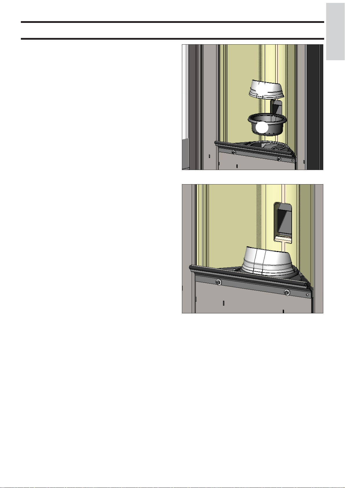
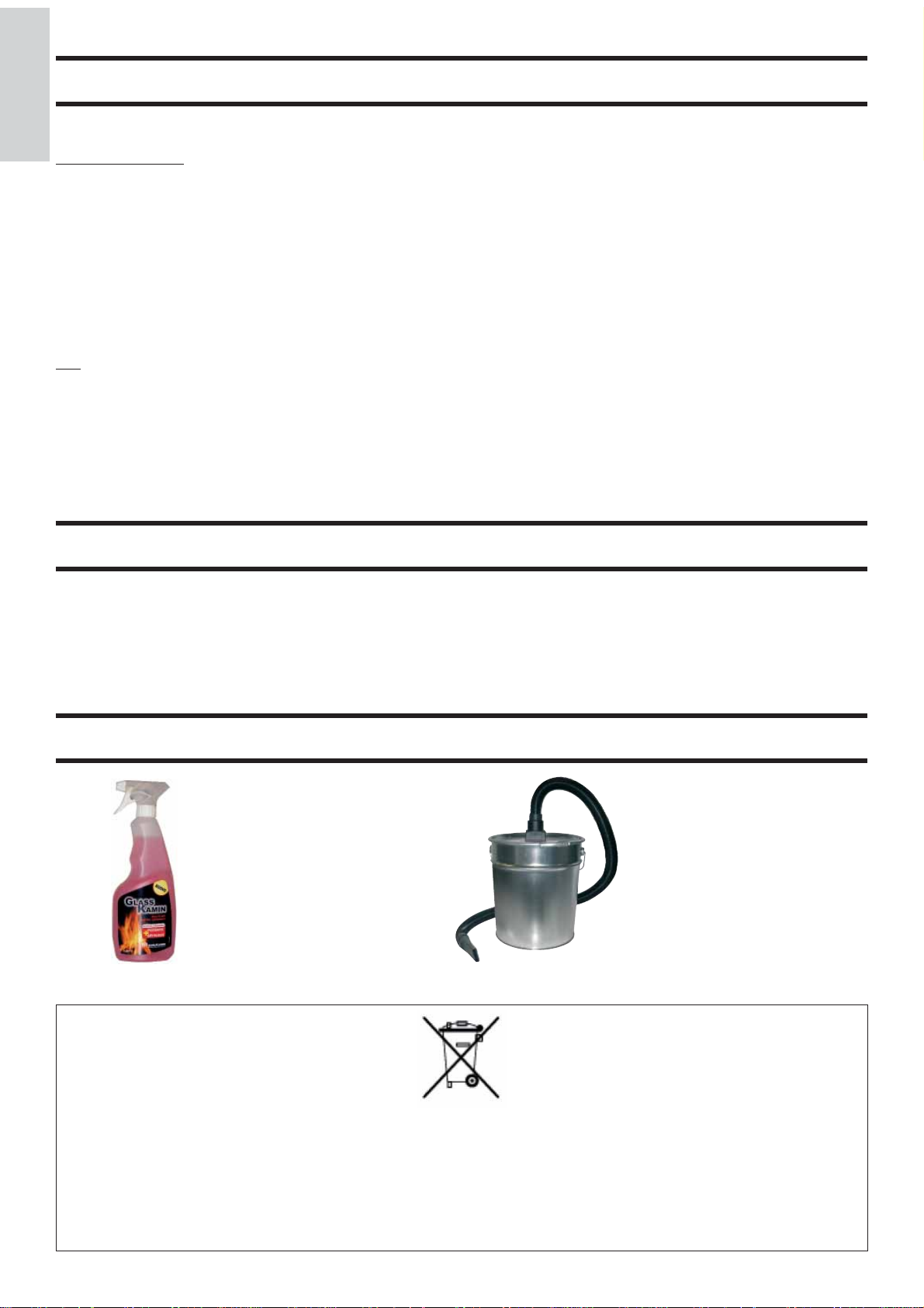
ATTENZIONE !!!
Dopo la normale pulizia, il NON CORRETTO accoppiamento del crogiolo superiore (A) (fi g. D) con il crogiolo inferiore
(B) (fi g. D) può compromettere il funzionamento della stufa.
Quindi prima dell’accensione della stufa, assicurarsi che i
crogioli siano accoppiati correttamente come indicato in (fi g.
E) senza presenza di cenere o incombusti sul perimetro di
contatto.
N.B.:
- E’ vietata ogni modifi ca non autorizzata
- Utilizzare pezzi di ricambio raccomandati dal costruttore
- L’impiego di componenti non originali implica la decadenza
della garanzia
fi g. E
- 13 -

CONSIGLI PER POSSIBILI INCONVENIENTI
In caso di problemi la stufa si arresta automaticamente eseguendo l’operazione di spegnimento e sul display si visualizza
ITALIANO
una scritta relativa alla motivazione dello spegnimento (vedi sotto le varie segnalazioni).
Non staccare mai la spina durante la fase di spegnimento per blocco.
Nel caso di avvenuto blocco, per riavviare la stufa è necessario lasciar avvenire la procedura di spegnimento (600 secondi
con riscontro sonoro) e quindi premere il tasto
Non riaccendere la stufa prima di aver verifi cato la causa del blocco e RIPULITO/SVUOTATO il crogiolo.
SEGNALAZIONI DI EVENTUALI CAUSE DI BLOCCO E INDICAZIONI E RIMEDI:
1) Segnalazione: Verifi ca/estratt. (interviene se il sensore giri estrattore fumi rileva un’anomalia)
Inconveniente: Spegnimento per rilevazione anomalia giri estrattore fumi
Azioni: • V erifi care funzionalità estrattore fumi (collegamento sensore di giri) (CAT)
• Verifi care pulizia canale da fumo
• Verifi care impianto elettrico (messa a terra)
• Verifi care scheda elettronica (CAT)
2) Segnalazione: Stop/Fiamma (interviene se la termocoppia rileva una temperatura fumi inferiore a un valore impostato inter
pretando ciò come assenza di fi amma)
Inconveniente: Spegnimento per crollo temperatura fumi
La fi amma può essere mancata perché:
- Verifi care mancanza pellet nel serbatoio
- Verifi care se troppo pellet ha soffocato la fi amma, verifi care qualità pellet (CAT)
- Verifi care se è intervenuto il termostato di massima (caso raro perché corrisponderebbe ad Over temperatura
fumi) (CAT)
- Intervento del pressostato di sicurezza per intasamento /occlusione del tubo di scarico dei fumi o della canna
fumaria (verifi care da un tecnico abilitato - spazzacamino)
- Intervento del termostato di sicurezza del serbatoio. Verifi care che attorno alla stufa non vi siano oggetti che
ostruiscano la ventilazione oppure i ventilatori siano guasti o fermi, in tal caso chiamare CAT.
.
3) Segnalazione: BloccoAF/NO Avvio (interviene se in un tempo massimo di 15 minuti non compare fi amma o non
è raggiunta la temperatura di avvio).
Inconveniente: Spegnimento per temperatura fumi non corretta in fase di accensione.
• Verifi care il corretto funzionamento del pressostato (CAT)
Distinguere i due casi seguenti:
NON è comparsa fi amma
Azioni: • Verifi care il posizionamento e pulizia del crogiolo
• Verifi care presenza di pellet nel serbatoio e nel crogiolo
• Verifi care funzionalità resistenza di accensione (CAT)
• Verifi care temperatura ambiente (se inferiore 3°C serve diavolina) e umidità.
• Provare ad accendere con diavolina (vedi pag. 10).
E’ comparsa fi amma ma dopo la scritta Avvio è comparso BloccoAF/NO Avvio
Azioni: • Verifi care funzionalità termocoppia (CAT)
• Verifi care temperatura di avvio impostata nei parametri (CAT)
4) Segnalazione: Mancata/Energia (non è un difetto della stufa).
Inconveniente: Spegnimento per mancanza energia elettrica
Azioni: • Verifi care allacciamento elettrico e cali di tensione.
5) Segnalazione: Guasto/TC (interviene se la termocoppia è guasta o scollegata)
Inconveniente: Spegnimento per termocoppia guasta o scollegata
Azioni: • Verifi care collegamento della termocoppia alla scheda: verifi care funzionalità nel collaudo a
freddo (CAT).
6) Segnalazione: °C fumi/alta (spegnimento per eccessiva temperatura dei fumi)
Inconveniente: Spegnimento per superamento temperatura massima fumi.
Azioni: Verifi care: • tipo di pellet (in caso di dubbi chiamare CAT)
• anomalia estrazione fumi (CAT)
• canale fumi ostruito, installazione non corretta (CAT)
• guasto del motoriduttore (CAT)
- 14 -

CONSIGLI PER POSSIBILI INCONVENIENTI
7) Segnalazione: Check button (segnala anomalia al pulsante di emergenza)
Azioni: • Verifi care lo stato del pulsante e del suo cavetto di collegamento alla scheda (CAT).
8) Segnalazione: “Control. Batteria”
Inconveniente: la stufa non si ferma, ma si ha la scritta a display.
Azioni: • Deve essere sostituita la batteria tampone sulla scheda elettronica (CAT).
Si ricorda che è un componente soggetto a regolare usura e quindi non coperto da garanzia.
9) Segnalazione: ALLARME CORRENTE ALTA: Interviene quando viene rilevato un anomalo ed eccessivo
assorbimento di corrente del motoriduttore.
Azioni: Verifi care funzionamento (CAT): motoriduttore - Collegamenti elettrici e scheda elettronica.
10) Segnalazione: ALLARME CORRENTE BASSA: Interviene quando viene rilevato un anomalo ed insuffi cente
assorbimento di corrente del motoriduttore.
Azioni: Verifi care funzionamento (CAT): motoriduttore - pressostato - termostato serbatoio - collegamenti elettrici e
scheda elettronica
11) Inconveniente: Radiocomando ineffi ciente
Azioni: • avvicinarsi alla stufa
• controllare e nel caso cambiare la pila
• Sincronizzazione con ricerca automatica all’attivazione: quando si inseriscono le batterie nel radiocoman
do verrà lanciata automaticamente una fase di ricerca canale radio e successivo collegamento con il prodotto
rilevato.
Al fi ne che ciò avvenga regolarmente, bisognerà aver cura di accendere il prodotto prima di inserire le pile
nel radiocomando e trovarsi nell’immediata vicinanza dell’antenna in modo da conquistare con certezza la
copertura radio.
• Sincronizzazione con ricerca automatica ad attivazione manuale: è possibile lanciare manualmente una
ricerca automatica di un prodotto, sarà suffi ciente eseguire le seguenti semplici operazioni avendo già inseri
to le pile nel radiocomando:
- Portarsi in vicinanza dell’antenna del prodotto ed assicurarsi che questo sia collegato alla rete elettrica.
- Con display spento (standby) premere e mantenere premuto il tasto 0/I per 10”.
- Trascorsi i 10”compare a display il messaggio “RICERCA RETE”, rilasciare quindi il tasto 0/I, signifi ca
che la fase di ricerca automatica si è attivata.
- In qualche secondo avverrà la sincronizzazione automatica del canale radio
ITALIANO
12) Inconveniente: Durante la fase di accensione “salta il differenziale” (per il Centro Assistenza Tecnica autorizzato
Edilkamin)
Azioni: • Verifi care le condizioni della resistenza di accensione, dell’impianto elettrico e dei componenti elettrici
13) Inconveniente: Aria in uscita non calda:
Azioni: • Verifi care funzionamento del ventilatore.
NOTA 1
Tutte le segnalazioni restano visualizzate fi no a che non si interviene sul radiocomando, premendo il tasto
Si raccomanda di non far ripartire la stufa prima di aver verifi cato l’avvenuta eliminazione del problema.
Importante riferire al CAT ( centro assistenza tecnica ) cosa segnala il pannello.
NOTA 2
Dopo 1000 kg di pellet consumati o altro valore impostato dal CAT durante la prima accensione, a display compare lampeggiante la scritta “manutenz_ione”.
La stufa funziona, ma è necessario far eseguire dal CAT abilitato Edilkamin una manutenzione straordinaria.
NOTA 3
Nel caso in cui la stufa a causa della qualità del pellet o dell’installazione particolarmente critica si intasi anticipatamente,
comparirà l’indicazione “Chiamare CAT”, procedere come per l’indicazione “manutenz_ione”
N.B.:
I comignoli e condotti di fumo ai quali sono collegati gli apparecchi utilizzatori di combustibili solidi devono venire puliti una
volta all’anno (verifi care se nella propria nazione esiste una normativa al riguardo).
Nel caso di omissioni di regolari controlli e della pulizia, si aumenta la probabilità di un incendio del comignolo.
IMPORTANTE !!!
Nel caso si manifestasse un principio di incendio nella stufa, nel canale da fumo o nel camino, procedere come segue:
- Staccare alimentazione elettrica
- Intervenire con estintore ad anidride carbonica CO
- Richiedere l’intervento dei Vigili del fuoco
2
.
NON TENTARE DI SPEGNERE IL FUOCO CON ACQUA!
Successivamente richiedere la verifi ca dell’apparrecchio da parte di un Centro di Assistenza Tecnica Autorizzato Edilkamin e far
verifi care il camino da un tecnico autorizzato.
- 15 -
CHECK LIST
ITALIANO
Posa e installazione
• Messa in servizio effettuata da CAT abilitato Edilkamin che ha rilasciato la garanzia
• Presa d’aria nel locale
• Il canale da fumo/la canna fumaria ricevono solo lo scarico della stufa
• Il canale da fumo (tratto di condotto che collega la stufa alla canna fumaria) presenta:
massimo 3 curve
massimo 2 metri in orizzontale
• il comignolo è posizionato oltre la zona di refl usso
• i tubi di scarico sono in materiale idoneo (consigliato acciaio inox)
• nell’attraversamento di eventuali materiali infi ammabili (es. legno) sono state prese tutte le precauzioni per evitare
incendi
Uso
• Il pellet utilizzato è di buona qualità e non umido
• Il crogiolo e il vano cenere sono puliti e ben posizionati
• Il portello è ben chiuso
• Il crogiolo è ben inserito nell’apposito vano
RICORDARSI di ASPIRARE il CROGIOLO PRIMA DI OGNI ACCENSIONE
In caso di fallita accensione, NON ripetere l’accensione prima di avere svuotato il crogiolo
Da integrare con la lettura completa della scheda tecnica
OPTIONAL
COMBINATORE TELEFONICO PER ACCENSIONE A DISTANZA (cod. 281900)
E’ possibile ottenere l’accensione a distanza facendo collegare dal CAT (centro assistenza tecnica autorizzato Edilkamin) il combinatore telefonico alla porta seriale dietro la stufa, tramite cavetto optional (cod. 640560).
ACCESSORI PER LA PULIZIA
GlassKamin (cod. 155240)
Utile per la pulizia del vetro ceramico
Bidone aspiracenere senza motore
(cod. 275400)
Utile per la pulizia del focolare
(da utilizzare in abbinamento ad un
aspirapolvere domestico)
INFORMAZIONI AGLI UTENTI
Ai sensi dell’art.13 del decreto legislativo 25 luglio 2005, n.151 “Attuazione delle Direttive 2002/95/CE,2002/96/CE e
2003/108/CE, relative alla riduzione dell’uso di sostanze pericolose nelle apparecchiature elettriche ed elettroniche, nonché allo
smaltimento dei rifi uti”. Il simbolo del cassonetto barrato riportato sull’apparecchiatura o sulla confezione indica che il prodotto
alla fi ne della propria vita utile deve essere raccolto separatamente dagli altri rifi uti. L’utente dovrà, pertanto, conferire l’apparec-
chiatura giunta a fi ne vita agli idonei centri di raccolta differenziata dei rifi uti elettronici ed elettrotecnici, oppure riconsegnarla al
rivenditore al momento dell’acquisto di una nuova apparecchiatura di tipo equivalente, in ragione di uno a uno.
- 16 -

Dear Sir/Madam
Congratulations and thank you for choosing our product.
Please read this document carefully before you use this product in order to obtain the best performance in complete safety.
For further details or assistance, please contact the DEALER where you purchased the product or visit our website
www.edilkamin.com and click on DEALERS.
NOTE
- After having unpacked the stove, ensure that its contents are complete and intact (remote control, “cold-hand” handle to open
the inner door, guarantee booklet, glove, CD/technical data sheet, spatula, dehumidifying salt).
In case of anomalies please contact the dealer where you purchased the product immediately.
You will need to present a copy of the warranty booklet and valid proof of purchase.
- Commissioning/ testing
Commissioning and testing must be performed by the DEALER. Failure to do so will void the warranty.
Commissioning, as specifi ed in standard UNI 10683/2012 consists in a series inspections to be performed with the insert installed
in order to ascertain the correct operation of the system and its compliance to applicable regulations
Details of your nearest Service Centre can be obtained from your dealer, from our website at www.edilkamin.com or by ringing
the helpline.
- Incorrect installation, incorrect maintenance, or improper use of the product, shall relieve the manufacturer from responsibility
for any damage resulting from the use of this product.
- series number, necessary for identifi cation of the stove, is indicated:
- on the top of the package
- in the warranty booklet found inside the fi rebox
- on the ID plate affi xed to the back side of the unit;
This documentation must be saved for identifi cation together with the valid proof-of-purchase receipt. The data contained
therein must be reported when requesting information and made available should servicing be required;
- All images are for illustration purposes only; actual products may vary.
ENGLISH
The undersigned EDILKAMIN S.p.a. with head offi ce headquarters at Via Vincenzo Monti 47 - 20123 Milan - Italy - VAT IT00192220192
Declares under its own responsability as follows:
The pellet stove illustrated below conforms to Regulation EU 305/2011 (CPR) and to the harmonised European Standard
EN 14785:2006
WOOD PELLET STOVES, trademark EDILKAMIN, called LOU
Year of manufacture: Ref. Data nameplate Declaration of performance (DoP - EK 095): Ref. data tag plate
In addition, it is hereby declared that:
the wood pellet stove LOU is in compliance with the requirements of the European directives:
2006/95/EC - Low voltage directive
2004/108/EC - Electromagnetic compatibility directive
EDILKAMIN S.p.a. will decline all responsability of malfunctioning or damage to the equipment in case of unauthorized
substitution, assembly or modifi cations of any sort on the said equipment on the part of non-EDILKAMIN personnel.
- 17 -
PRINCIPLE OF OPERATION
SAFETY INFORMATION
The LOU stove is completely airtight with respect to the
room in which it is installed; this means that the air (for
combustion and glass-cleansing) is taken directly from the
external environment, thus avoiding even minimum use of
the air of the room in which it is installed.
It is consequently suitable for use in houses defi ned at
“PASSIVE”.
To respect this hermetic property of the stove, the pipe for the
input of the comburent air must be connected with the external
environment using suitable airtight pipes and connections.
ENGLISH
The stove produces hot air using wood pellets as fuel, with
electronically controlled combustion. Hereunder is the explanation of its functions (the letters refer to fi gure 1).
The fuel (pellets) is provided by the storage hopper (A) and,
to the combustion chamber (D) by means of a feed screw (B),
which is driven by a gear motor (C).
The pellets are ignited by the air that is heated by an electrical
resistance (E) and drawn into the combustion chamber
by a smoke extractor (F).
The fumes produced by the combustion are extracted from the
combustion chamber by the same extractor fan (F) and expelled
from the vent (G) located in the lower rear of the stove.
The combustion chamber (made in material called Vermiculite)
is closed at the front by two overlapping doors:
- an outer door in ceramic glass (to be opened with the glove
provided)
- in inner door in ceramic glass in contact with the fi re (to be
opened with the special “cold-hand” handle).
Fuel quantity, smoke extraction and combustion air supply
are all controlled by an electronic control board, which is
equipped with Leonardo® software to achieve high combustion
effi ciency and low emissions.
All phases of operation can be managed via radio remote
control.
The stove is equipped with a serial port to connect an optional
cable (code 640560) to be connected to devices that allow
remote ignition (e.g. remote telephone, local thermostat, ect.).
The stove is designed to heat, through automatic pellet combustion in the hearth, the room where it is installed, both by
radiation and the air that comes out of the front grille (I).
• The appliance is not designed to be used by people, including
children, with reduced physical, sensorial or mental abilities.
Children must be supervised to ensure they do not play with
the appliance.
• The main risks that may derive from using the stove pertain
to non-compliance with installation instructions, direct contact
with live electrical parts (internal), contact with the fi re or hot
parts (glass, pipes, hot air output), when extraneous substances
or non-recommended fuel are introduced, or due to incorrect
maintenance or by repeatedly pressing the ignition button without having emptied the crucible.
• Only use certifi ed, high quality, 6 mm diameter wooden
pellets for fuel.
• Should components fail, the stoves are equipped with safety
devices that guarantee automatic shutdown. These are activated
without any intervention required.
• In order to function correctly, the stove must be installed in
accordance with the instructions given herein and the door
must not be opened during operation: combustion is fully
automatic and requires no intervention.
• Under no circumstances should any foreign substances be
entered into the hearth or hopper.
• Do not use fl ammable products to clean the smoke channel
(the fl ue section connecting the stove smoke outlet to the
chimney fl ue).
• The hearth and hopper parts must only be cleaned when
COLD.
• The glass can be cleaned when COLD with a suitable product
(e.g. GlassKamin Edilkamin) and a cloth.
• Avoid opening the door of the combustion chamber when the
stove is hot; wait until it has cooled down naturally.
• The stove must not function if the door is open, if the glass is
broken or if the pellet-loading port is open.
• It must not be used as a step ladder or a base on which to rest
any object.
I
D
fi g. 1
A
B
F
E
C
G
• Do not lay laundry directly on the stove to dry. Any clothes
horse or similar must be placed at a safe distance from the
stove (danger of fi re).
• Make sure the stove is installed and ignited the fi rst time by
Edilkamin-qualifi ed CAT personnel (technical assistance centre)
in accordance with the instructions provided here within; this is
an essential requirement for the validation of the guarantee.
• When the stove is in operation, the exhaust pipes and door
become very hot (do not touch without wearing the thermal
glove).
• Do not place anything, which is not heat resistant near the
stove.
• NEVER use liquid fuel to ignite the stove or rekindle the embers.
• Do not obstruct the ventilation apertures in the room where
the stove is installed, nor the air inlets of the stove itself.
• Do not wet the stove and do not go near electrical parts
with wet hands.
• Do not use reducers on the smoke exhaust pipes.
• The stove must be installed in a room that is suitable for fi re
prevention and equipped with all that is required (power and air
supply and outlets) for the stove to function correctly and safely.
• SHOULD IGNITION FAIL, DO NOT RE-IGNITE UNTIL
YOU HAVE EMPTIED THE COMBUSTION CHAMBER.
- 18 -
DIMENSIONS
FRONT
112
46
46
BACK
Combustion
Ø 4 cm aria
air Ø 40 mm
combustione
39
15 16
Smoke outlet Ø
Ø 8 cm uscita fumi
80 mm
33
ENGLISH
112
SIDE
SYSTEM
52
46
52
- 19 -
CHARACTERISTICS
• ELECTRONIC EQUIPMENT
LEONARDO® is a combustion safety and control system which allows optimal performance in all
conditions thanks to two sensors measuring the pressure level in the combustion chamber and smoke
temperature.
The detection of and subsequent optimisation of these two parameters is continuous in order to correct
operation anomalies in real time.
The LEONARDO
ENGLISH
characteristics of the chimney fl ue (bends, length, shape, diameter, etc.) and environmental conditions
(wind, humidity, atmospheric pressure, installations at high altitude, etc.).
The standards for installation must be respected.
The LEONARDO® system is also able to recognise the type of pellets and automatically adjust the fl ow
moment by moment to ensure the required level of combustion.
• ELECTRONIC CIRCUIT BOARD
®
system offers constant combustion, automatically regulating the draft based on the
Emergency button
Vacuum gauge
Control panel
remote-control
device
RES safety
Smoke-expulsion motor
smoke rpm
RPM ambient
Lithium
CR2032
backup
battery
tank
micro-port
TM 80°C
Tank
SCREW
Reading points
Vacuum gauge
+
thermocouple
Port on back of stove
ingnition element
thermocouple
AMBIENT-AIR SENSOR
230 vac power
supply
50hz +/-10%
ventilation ambient
SERIAL PORT
The Dealer can install an optional on the AUX outlet for controlling the process of
switching on and off (e.g. telephone remote, local thermostat), located at the rear of the
stove. This can be connected via special optional trestle (code 640560).
BACKUP BATTERY
A backup battery is found on the control board (3-Volt CR 2032 battery). Its malfunction is indicated with the following messages (not considered a defect but due to
normal wear-and-tear): “Battery check”. For more detailed information, please contact
the DEALER who performed the fi rst 1st ignition.
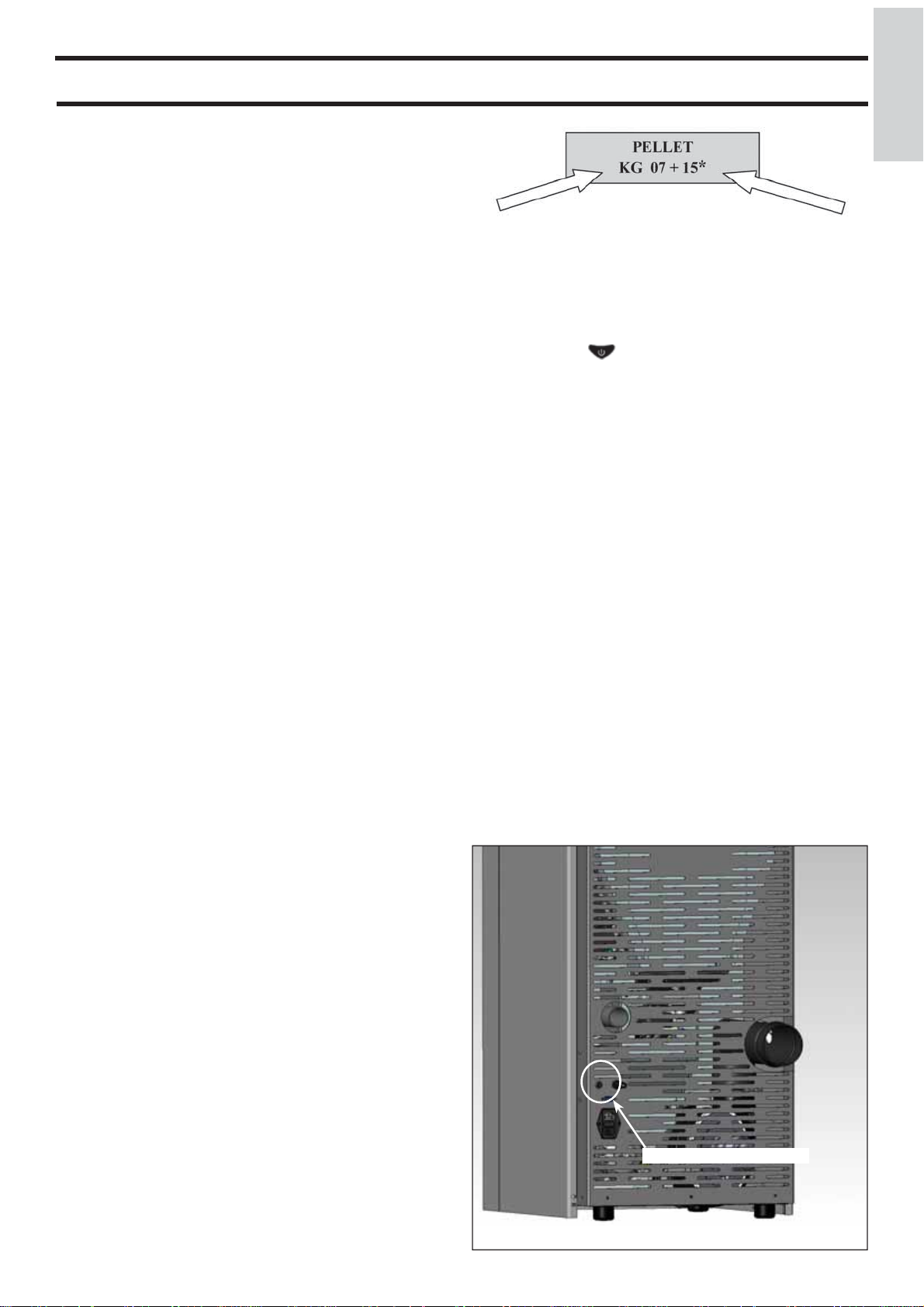
FUSE *
Two fuses are inserted in the socket with switch, located on the back of the stove, one
of which operational * and the other is held in reserve **.
- 20 -
*
*
*
CHARACTERISTICS
THERMO TECHNICAL CHARACTERISTICS according to EN 14785
Nominal power Reduced power
Heat input (burnt) 9 2,5 kW
Heat output 8 2,4 kW
Yield / Effi ciency 93 95,1 %
Emissions CO 13% O2 0,013 0,059 %
Fume temperature 129 63 °C
Fuel consumption 1,9 0,5 kg/h
Hopper capacity 24 kg
Autonomy 11 42 hours
Heatable volume * 210 m
Smoke outlet pipe diameter (male) 80 mm
Air intake pipe diameter (male) 40 mm
Weight including packaging 200 kg
TECHNICAL DATA FOR THE DIMENSIONING OF THE FLUE
Nominal power Reduced power
Heat output 8 2,4 kW
Temperature of fumes on exit from the discharge pipe 200 110 °C
Minimum draught 12 10 Pa
Fume fl ow capacity 5,8 3,2 g/s
Classifi cation of combustion chamber according to DIBt FB 22 FC
* The heatable room dimensions are calculated on the basis of home insulation in compliance with Italian law 10/91, and subsequent changes together with an expected heat output of 33 Kcal/m³ per hour.
52x
3
-
ENGLISH
ELECTRICAL CHARACTERISTICS
Power supply 230 Vac +/- 10% 50 Hz
On/off switch Yes
Average power consumption 100 W
Power consumption during ignition 400 W
Remote control frequency Radio waves 2,4 GHz
Protection on mains power supply* (see page 20) T2A, 250 Vac, 5x20 Fuse
Protection on electronic circuit board T2A, 250 Vac, 5x20 Fuse
N.B.
1) keep in mind that external devices can cause interference to the operation of the circuit board.
2) warning: activity on live components, maintenance and/or checks must be carried out by qualifi ed personnel.
(before carrying out any maintenance, disconnect the appliance from the mains electricity)
The above data are indicative and are those resulting during certifi cation on the part of the notifi ed body.
EDILKAMIN s.p.a. reserves the right to change the products at its discretion without notice.
SAFETY DEVICES
• THERMOCOUPLE:
Placed at the smoke outlet to detect the temperature.
Turns the stove on and off and controls its operation based on defi ned parameters.
• VACUUM GAUGE:
Positioned on the smoke extractor, which detects the vacuum value (compared to the installation environment) in the combustion
chamber.
• SAFETY THERMOSTAT:
Trips when the temperature inside the stove is too high. It stops pellet loading, causing the stove to go out.
• SAFETY PRESSURE SWITCH:
This is activated if the vacuum inside the combustion chamber is insuffi cient for it to function correctly.
- 21 -
INSTALLATION
All local and national laws and European standards must be
met when installing and using the appliance. In Italy, refer to
the UNI 10683/2012 standard, as well as any regional or local
health-authority regulations.
In France, refer to Decree 2008-1231 art. R131-2.
It is necessary to refer to regulations in force in each country. If
installing in an apartment building, check with the management
company fi rst.
ENGLISH
VERIFY COMPATIBILITY WITH OTHER DEVICES
In Italy the stove MUST NOT be installed in the same space
as type B gas heating equipment (e.g. gas boilers, stoves, and
equipment served by an extraction hood) as the stove may cause a vacuum in the space which may compromise or infl uence
how these units work. Pursuant to standard UNI 10683, the
stove can also be installed in a bedroom.
VERIFYTHE POWER SUPPLY CONNECTION
(the plug must be accessible)
The stove is supplied with a power cable that is to be connected
to a 230V 50 Hz socket, preferably fi tted with a magnetother-
mic switch. Voltage variations exceeding 10% can damage
the stove (unless already installed, an appropriate differential
switch must be fi tted). The electrical system must comply
with the law; particularly verify the effi ciency of the earthing
system. The power line must have a suitable cross-section for
the stove’s power. An inadequate earthing system can cause
anomalies for which Edilkamin cannot be held liable.
POSITIONING
The stove must be level for it to function correctly.
Verify the bearing capacity of the fl oor.
FIRE PREVENTION SAFETY DISTANCES
The stove must be installed in compliance with the following
safety conditions:
- minimum distance from fl ammable materials around the sides
and back of the stove: 20 cm
- fl ammable materials must not be placed less than 80 cm from
the front of the stove.
If it is not possible to comply with the above-mentioned distances, technical and construction-related provisions must be
taken to prevent fi re hazards.
If connected to wooden walls or other fl ammable materials, the
smoke exhaust pipe must be insulated.
SMOKE OUTLET
The stove must have its own smoke outlet (the smoke cannot be discharged into a smoke fl ue used by other devices).
In Germany, discharge can be by multiple fl ue with explicit
verifi cation on the part of a chimney-sweep.
The smoke is discharged through the 8 cm diameter outlet at
the back of the stove. The smoke outlet must be connected to
outside by means of suitable steel pipes EN 1856 certifi ed.
The pipe must be hermetically sealed.
The material used to seal and if necessary insulate the pipes,
must be resistant to high temperatures (high temperature silicone or mastic). The only horizontal section allowed may be up
to 2 m long up to three 90° bends (in relation to the vertical).
A vertical section of at least 1.5m and an anti-wind terminal
is necessary (if the discharge outlet is not in a chimney fl ue
reference UNI 10683/2012). In France, with regard to fumes
discharge, refer to DTU 24.1 and DTU 24.2.
The vertical duct can be internal or external. If the smoke channel is outside, it must be appropriately insulated. If the smoke
channel is fi tted inside a chimney fl ue, the latter must be suita-
ble for solid fuel. If it is wider than 150 mm in diameter it must
be improved by entering a pipe that has a suitable cross-section
and is made of suitable material (e.g. 80 mm diameter steel).
All sections of the smoke duct must be accessible for inspection. The chimney pots and smoke ducts connected to the solid
fuel appliances must be cleaned once a year (verify whether a
specifi c legislation exists in your country).
Failure to regularly inspect and clean the stove increases the
probability of a fi re occurring in the chimney pot. In that case,
proceed as follows: Do not use water to extinguish the fi re;
Empty the pellet hopper; Contact specialist personnel before
reigniting the stove.
The stove is designed to work under any weather conditions.
In case of particular conditions, such as strong wind, the safety
system may be activated, which results in the stove being
extinguished. If this happens, do not operate the stove with
the safety devices disabled. If the problem persists, contact our
Technical Service Department.
TYPICAL EXAMPLES
Fig. 1 Fig. 2
AIR INTAKE
The stove is also suitable for installation in houses defi ned as
“passive”. In this case, the air for combustion must be taken
by connecting (hermetically) the input vent at the back of the
stove with the external environment by means of a ø 4 cm pipe.
Make sure that the external air intake is positioned so that it
cannot be obstructed. In France, refer to Decree 2008-1231 art.
R131-2 for the above installations.
In all other types of houses, the stove can be installed in the
traditional manner and therefore also using the air of the
environment in which it is placed (in any case, the technical
standards of reference must always be respected).
The pipe must be less than 1 metre long and have no bends.
It must end with a section at 90° facing downwards or be fi tted
with a wind guard. in any case the air-intake duct must be a
free section of at least 12 cm². The external terminal of the air
inlet channel must be protected with an anti-insect netting that
does not reduce the 12 cm² through passage.
inspection
A: insulated steel fl ue
B: minimum height of 1.5 m and in any case above the height of the
roof gutter
C-E: air intake from inside room (minimum internal section: 80 cm²)
D: steel fl ue, inside existing brick-built chimney.
CHIMNEY POT
The main characteristics are:
- an internal cross-section at the base, which is the same as that
of the chimney fl ue
- an outlet cross-section which is no smaller than twice that of
the chimney fl ue
- its position must be high enough to catch the wind and avoid
downdraft areas in turbulent wind, it must be high enough to
catch the wind and avoid downdraft areas in turbulent wind.
- 22 -
INSTRUCTIONS FOR USE
Commissioning must be done by a Technical Service Centre
authorised by Edilkamin (CAT) prior to ignition and testing
according to the UNI 10683/2012 standard.
This standard indicates the control operations to be carried out,
aimed at ascertaining correct system function.
B
The CAT will also provide for calibrating the stove on the
basis of the type of pellets and the installation conditions, thus
allowing for the effectiveness of the guarantee.
If the fi rst ignition is not carried out by a C.A.T. authorised by
Edilkamin, the guarantee shall not be effective.
For information, consult the website www.edilkamin.com
There may be a slight smell of paint the fi rst few times it is
ignited, however, this will disappear quickly.
Before igniting you must check:
• that installation is correct
• the power supply
• that the door closes properly to a perfect seal
• that the combustion chamber is clean
• that the display is on standby (the date, power or temperature
fl ashes).
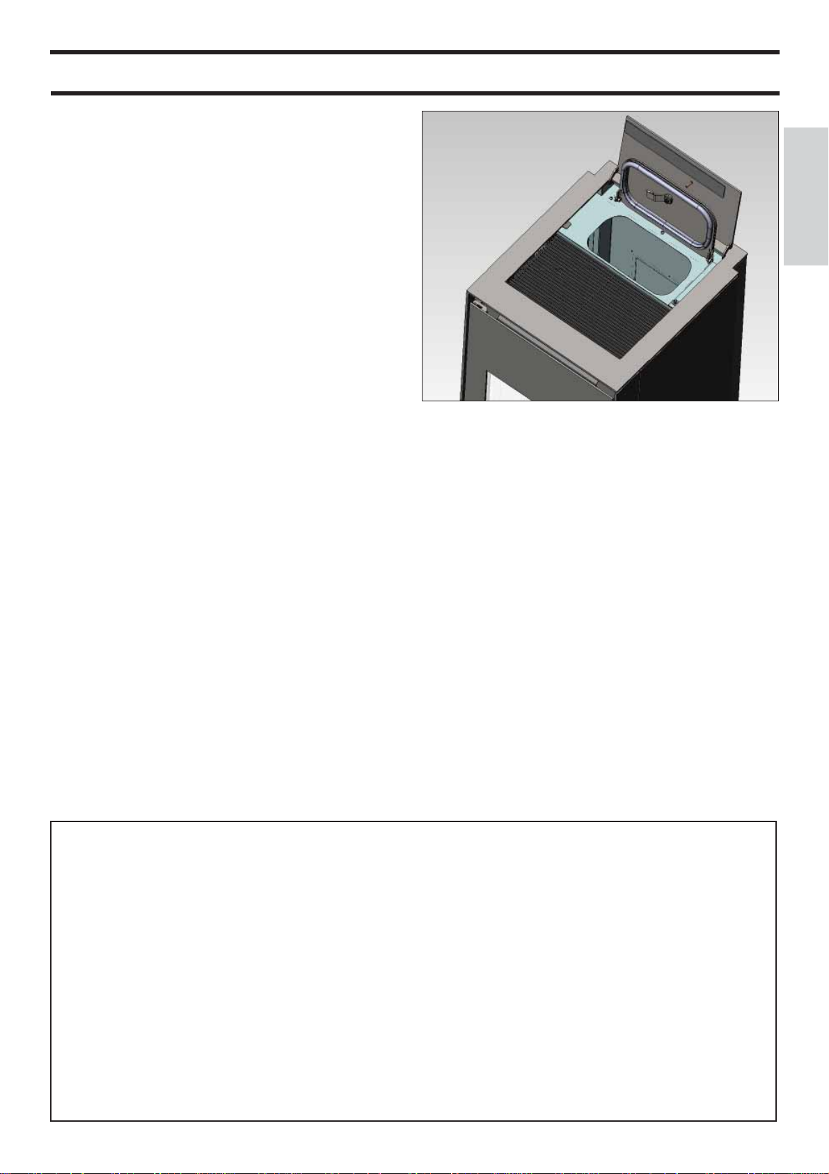
FILLING THE PELLET HOPPER
To gain access to the reservoir, open the two doors at the rear
part of the top (A and B - fi g. 1).
N.B.
1) During this operation, the bag of pellets MUST NEVER
be placed on the upper grill, otherwise the plastic bag,
coming into contact with the heat, could ruin the paintwork
on the top.
2) Use the special glove provided if you load the stove while
it is functioning and therefore hot.
3) You are recommended to load the pellets into the reservoir within 40 second of opening the reservoir.
fi g. 1
A
ENGLISH
NOTE regarding the fuel.
LOU is designed and programmed to burn wood pellets with 6
mm diameter.
Pellets are a type of fuel in the form of little cylinders, made
from compacted sawdust, compressed under high pressure
with no adhesives or foreign materials.
They are sold in bags of 15 kg.
For the stove to function properly, you MUST NOT burn
anything else in it. Using other materials (including wood)
will render the warranty null and void. Such use is detected by
laboratory analyses. Edilkamin has designed, tested and programmed their stoves to guarantee the best performance when
pellets with the following characteristics are used:
diameter: 6 millimetres
maximum length: 40 mm
maximum moisture content: 8%
calorifi c value: at least 4300 kcal/kg.
If pellets with different characteristics are used, the stoves
must be recalibrated using a similar procedure to that carried
out by the DEALER when the stove is ignited the fi rst time.
Using unsuitable pellets may: decrease effi ciency; cause
malfunctions; stop the stove from functioning due to clogging,
dirt on the glass, unburnt fuel, etc.
A simple, visual analysis of the pellets may be carried out:
Good quality: smooth, uniform length, not very dusty.
Poor quality: with longitudinal and transverse cracks, very
dusty, various lengths and mixed with foreign matter.
- 23 -
INSTRUCTIONS FOR USE
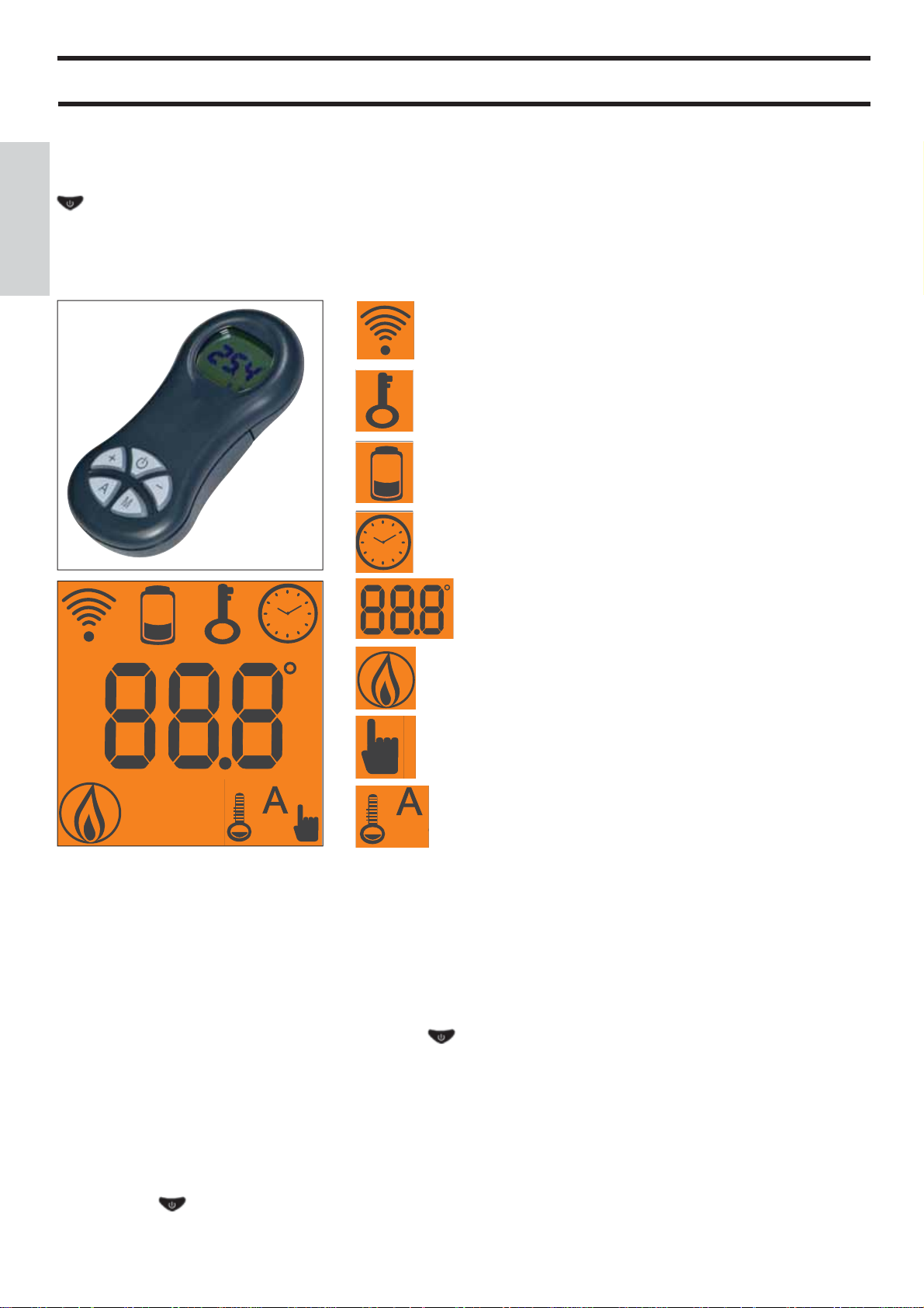
REMOTE CONTROL
This controls all the functions.
Key to buttons and display:
: to turn off and on (to go from “remote control on standby” to “remote control on”)
+/- : to increase/decrease the various regulations
A : to select Automatic function
M : to select Manual function and access the control and programming menus
ENGLISH
- icon fl ashing: remote control searching for network
- icon fi xed: remote control with connection enabled
keypad locked (press “A” and “M” in parallel for a few seconds
to lock or unlock the keypad)
fl at battery (3 mini alkaline batteries type AAA)
programming enabled
alphanumeric display consisting of 16 fi gures arranged in two
lines of 8 fi gures
- icon fl ashing: stove turning on
- icon fi xed: stove working
manual adjustment function (display shows working power)
automatic function (display shows temperature)
The display also shows other useful information in addition to the icons described above.
- Stand-by position:
shows room temperature (20°C), kg of pellets (15 kg) remaining in tank and current time (15:33)
- Manual work phase:
shows power set (Power 1), room temperature (20°C), kg of pellets and autonomy remaining (15 kg 21 hrs)
- Automatic work phase:
shows temperature set (Set 22°C), room temperature (20°C), kg of pellets and autonomy remaining (15 kg 21 hrs).
DO NOT PRESS THE BUTTON MORE THAN ONCE .
Note: If the radio control is not used for a few seconds, the display will go dark as it has moved into the power-saving function.
The display can be reactivated by pressing any button.
Fan de-activation
To de-active/re-activate the fan of the stove, proceed as follows: press the button M for 2”, press the button + twice; the wording
“COMFORT AIR” will appear on the display; confi rm this with the button M; you will thus gain access to the fan selection menu.
With the +/- buttons, the display will move alternatively from COMFORT AIR (ventilation on) to “AIR OFF” (ventilation off);
press the button to memorise the setting.
- 24 -

INSTRUCTIONS FOR USE
Filling the cochlea.
The fi rst time you use the product, or should the tank be com-
pletely emptied of pellets, to fi ll the coclea press both keys “+”
and “–” on the remote control at the same time, holding for a
few seconds. As you release the keys, the display should show
the wording “LOAD”. This should be carried out before ignition if the stove has stopped due to having run out of pellets,
at the end of operation to empty the combustion pot before
turning.
It is quite normal for some pellets to remain, that the cochlea
cannot suction.
Automatic igniting.
With the stove on stand-by, press and hold the key
remote control for 2 seconds. This will start-up the
ignition procedure, showing the wording “START”. At the
same time, a countdown in seconds begins (from 1020 to 0).
Ignition is not at a preset time, however: its duration is automatically shortened if the board reports that certain tests have
been passed. The fl ame appears after about 5 minutes.
Manual igniting.
Temperatures of below 3°C will not allow the electrical resistance to heat suffi ciently. In this case, or should the
resistance be temporarily out of action, Diavolina® type fi re-
starters can be used.
Insert a piece of lit Diavolina into the combustion chamber,
close the door and press the remote control.
POWER REGULATION
• Remote control manual operation
With the stove working, press the key “M” on the remote control once. The display will show the word “POWER P”.
(specifying the power at which the insert is working). Press the
keys “+” or “–” to increase or decrease the insert’s
working power (from “POWER P1” to “POWER P5”).
• Remote control automatic operation
Press key “A” to switch to automatic operation, adjusting the
temperature desired for the room (use the “+” and “–” keys
to set the temperature from 5°C to 35°C, and the stove will
regulate working power required to reach the temperature set.
If a temperature below that of the room is set, the insert will
stay on “POWER P1”.
Turning off
With the stove running, press and hold the key rom the remote control for 2 seconds. The turn-off procedure will begin,
showing a countdown on the display from 9 to 0 (for a total of
10 minutes).
The turn-off phase involves:
• Interruption of pellet supply
• Maximum ventilation
• Smoke expulsion motor
Never pull the plug out whilst the device is still in the process
of turning off.
, on the
Operations for switching on, switching off and regulating
power can be carried out by means of the red emergency button
placed on the back of the stove (see page 26).
Weekly timer
Press and hold the “M” key on the remote control for 2 seconds. This turns on the clock regulation and by pressing the ‘+’
key, the weekly timer function is accessed, with the display
showing the description “PROGRAMM ON/OFF”.
This function allows you to select the type of programming,
which allows a maximum of three ignitions to be set.
As you confi rm the display with the key “M”, one of the fol-
lowing options will appear:
NO PROG. (no programme set)
DAILY PROGRAM (single programme for every day of the
week)
WEEKLY PROGRAM. (specifi c programme for each day
individually)
Use the “+” and “–” keys to switch between programmes.
Confi rming by pressing the “M” key “DAILY PROGRAM.”
and pressing the “+” key, the choice of the number of programmes (ignition/extinguishing) per day can be made.
Use the “DAILY PROGRAM” to set identical programme/s for
every day of the week.
By then pressing the “+” key, the following can be seen:
- Prog. no.
- 1st prog. (one turn on and one turn off per day), 2nd prog.
(identical), 3rd prog. (identical)
Use the “–” key to show in reverse order.
If the 1st programme is selected, the turn on time is shown.
The display shows: 1 “ON” at 10 Use the “+” and “–” key to
change the hour. Confi rm with the “M” key (All 1 On/Hour
10).
The display shows: 1 “ON” at 30 Use the “+” and “–” key to
change the minutes. Confi rm with the “M” key (1 Off min).
The same applies for the turn-off time to be set and for subsequent turning on and off.
Confi rm by pressing “M” and the wording “SAVE??” will
appear on the display.y.
When confi rming ”WEEKLY PROGRAM”, you will need to
choose the day to which the programming is to apply:
7 Sat; Progr.1; 1 Mon ; 2 Tues; 3 Wed; 4 Thurs; 5 Fri; 6 Sa;
Once the day is set, use the keys “+” and “+” and confi rm by
pushing the “M” key to choose 1 to 3 ignitions, to programme
in the same way as for the “DAILY PROGRAM”, choosing
whether or not to enable a programme for each day of the
week, and if so choose the number of interventions and at what
times.
Should you make an error during programming, you can leave
the programme without saving. As you press a key, , the
display will show the word “no SAVE”.
ENGLISH
OPERATIONS THAT CAN ONLY BE CARRIED OUT BY
REMOTE CONTROL
Clock regulation
Press and hold the key “M” for 2 seconds to access the “Clock”
menu. This allows you to set the internal electronic board
clock. By then pressing the key “M”, the following data appears in sequence and can be regulated:
day, month, year, hour, minutes, day of the week.
The wording “SAVE??” will appear for confi rmation with “M”.
This will allow you to check that the operations performed are
correct, prior to completion (the wording “SAVE” will then be
shown on the display).
- 25 -
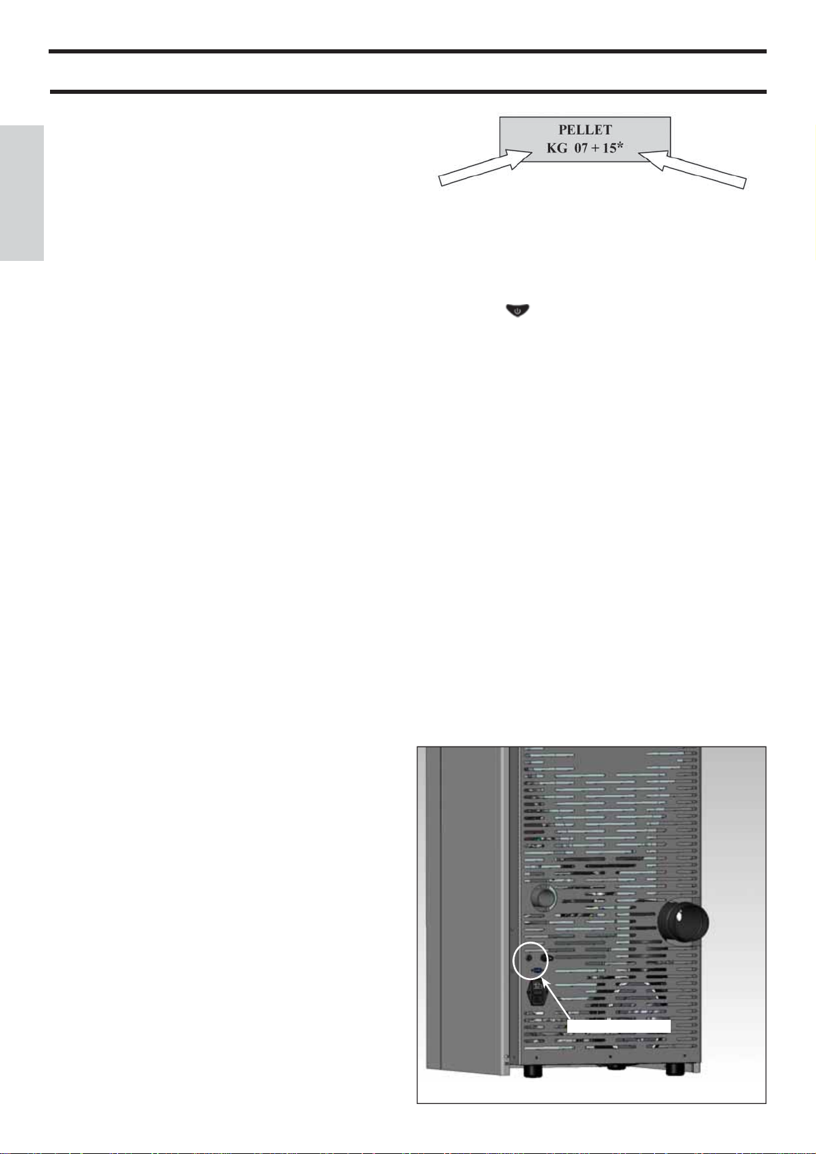
INSTRUCTIONS FOR USE
Changing pellet loading (with self-regulation deactivated)
When the “M” key on the radio control is held down for two
seconds and the display is scrolled using the “+” and “–” keys,
you come across the “User’s Menu”. When this is confi rmed
the display reads “ADJ-PELLET ; ADJ-DRAUGHT and RADIO MENU” (CAT). The pellet drop can be adjusted manually
by changing the capacity in percentage terms (+/- 30 %).
By confi rming this function with the menu key, you can access
ENGLISH
the function to adjust pellet loading. By decreasing the
value set, pellet loading is decreased. By increasing the value
set, pellet loading increases. This function is useful if
changing the pellet type for which the stove has been calibrated
and loading therefore needs correcting.
Kg remaining in tank
then use the “+” key to take the fi gure (*) to the value equal to
the Kg of pellets loaded (15 kg in the above example).
4. press the “M” key to confi rm
5. press the key to exit.
Kg caricati
Should this correction not suffi ce, contact the Edilkamin-autho-
rised Dealer, to establish the new operating axis.
Notes on fl ame variability
Flame status may vary depending on the type of pellet used,
in addition to normal solid fuel fl ame variability and regular
combustion chamber cleaning carried out automatically by the
boiler.
(N.B.: which does NOT replace necessary cold suction by the
user prior to ignition).
RESERVE WARNING
The stove is fi tted with an electronic function that detects the
residual quantity of pellets in the tank.
The detection system is integrated into the electronic board,
allowing you to see how many hours and kg are left until
pellet exhaustion, at all times. For correct system function, it is
important that the following procedure is followed during the
fi rst ignition (by the Dealer).
This provides a reference indicator. Greater precision is
obtained by regularly zeroing the system before fi lling it again.
Edilkamin does not accept any responsibility for differences
from what is indicated (which may be due to external factors).
After having completed the above procedure, after having consumed the 15 kg, the wording “Reserve” will appear
fl ashing at intervals. After which the operation must be repeated, from point 1 to point 5.
EMERGENCY BUTTON
If the remote control device does not work, you can carry out
the basic functions by means of a red emergency button placed
on the back of the stove (see fi g. 1).
Push this button once or more times to activate the required
function:
1. STOVE OFF
by pressing the red button for 2 seconds this turns on.
2. STOVE ON
by pressing the red button for 2 seconds this turns off.
3. STOVE ON
manual mode, by pressing the red button, you go from P1 to
P3.
4. STOVE ON
automatic mode, by pressing the red button, you go from 5°C
to 30°C.
Pellet reserve system
Before enabling the system, you need to load a sack of pellets
into the tank and use the stove until the loaded
fuel has run out. This allows for a short system road test.
After this, the tank can be fi lled completely and the stove
started up.
When running, at the time at which a whole 15 kg sack of pellets can be loaded, the display will show the word
“Reserve” fl ashing.
At this point, after having poured in a sack of pellets, you need
to ‘inform’ the memory that you have loaded 15 kg.
To do so, proceed as follows:
1. press the “M” key (for approximately 3-4 seconds) until the
word “Clock” appears.
2. press the “+” key until the word “Reserve” appears.
3. press the “M” key until the following screen appears,
emergency button
fi g. 1
- 26 -
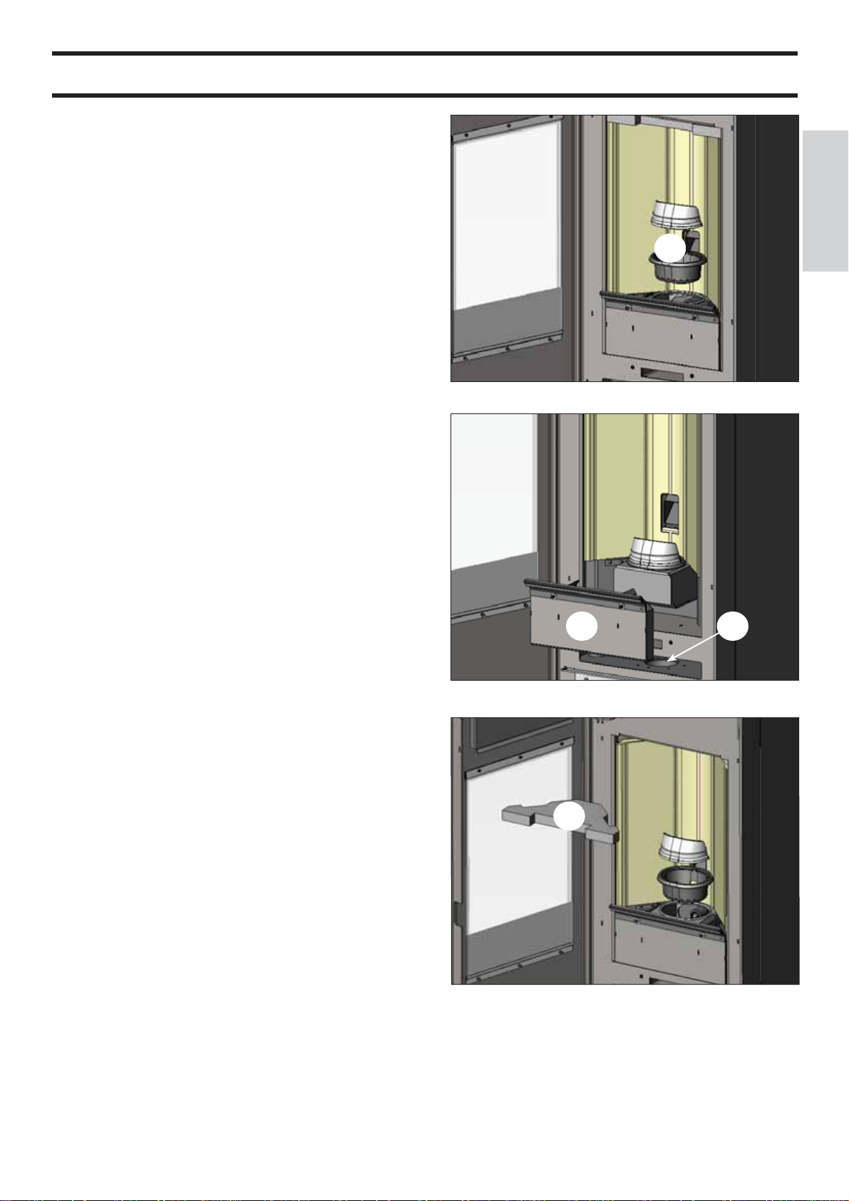
MAINTENANCE
Before performing any maintenance, disconnect the appliance from the mains.
Regular maintenance is required for the stove to function
correctly.
Any problems resulting from lack of maintenance will immediately void the warranty.
DAILY MAINTENANCE
Operations must be performed when the stove is off, cold
and unplugged from the power supply
• Cleaning must be carried out with a vacuum cleaner. (see
optional extras page 31).
• Open the door, extract the fi re box (1 - fi g. A) and tip the
residue into the ash drawer (2 - fi g. B).
• DO NOT EMPTY THE RESIDUE OUT INTO THE PELLET HOPPER.
• Pull the ash drawer (2 - fi g. b) out and empty it into a non-
fl ammable container (the ash may still have some parts that are
hot and/or embers).
• Vacuum out the inside of the fi re box, fi re grate, and space
around the fi re box, into which the ash falls.
• Remove the fi re box (1 - fi g. A) and remove any encrustation
using the brush provided, clearing any clogging in the holes.
• Vacuum the fi re box, clean the contact edges between the fi re
box and its seating.
• Clean the glass, if necessary (when cold).
Never vacuum hot ash, it can make the vacuum cleaner
breakdown and represents a fi re risk.
WEEKLY MAINTENANCE
• Remove the ceiling (3 - fi g. C) and tip the residue into the ash
drawer (2 - fi g. B). The ceiling is a component subject to wear
and Edilkamin does not accept responsibility for it, especially if any breaks are due to extracting or putting it back in its
seating.
• Clean the combustion chamber and the smoke-extraction fan
compartment (4 - fi g. B).
fi g. A
fi g. B
3
2
ENGLISH
1
4
- 27 -
fi g. C
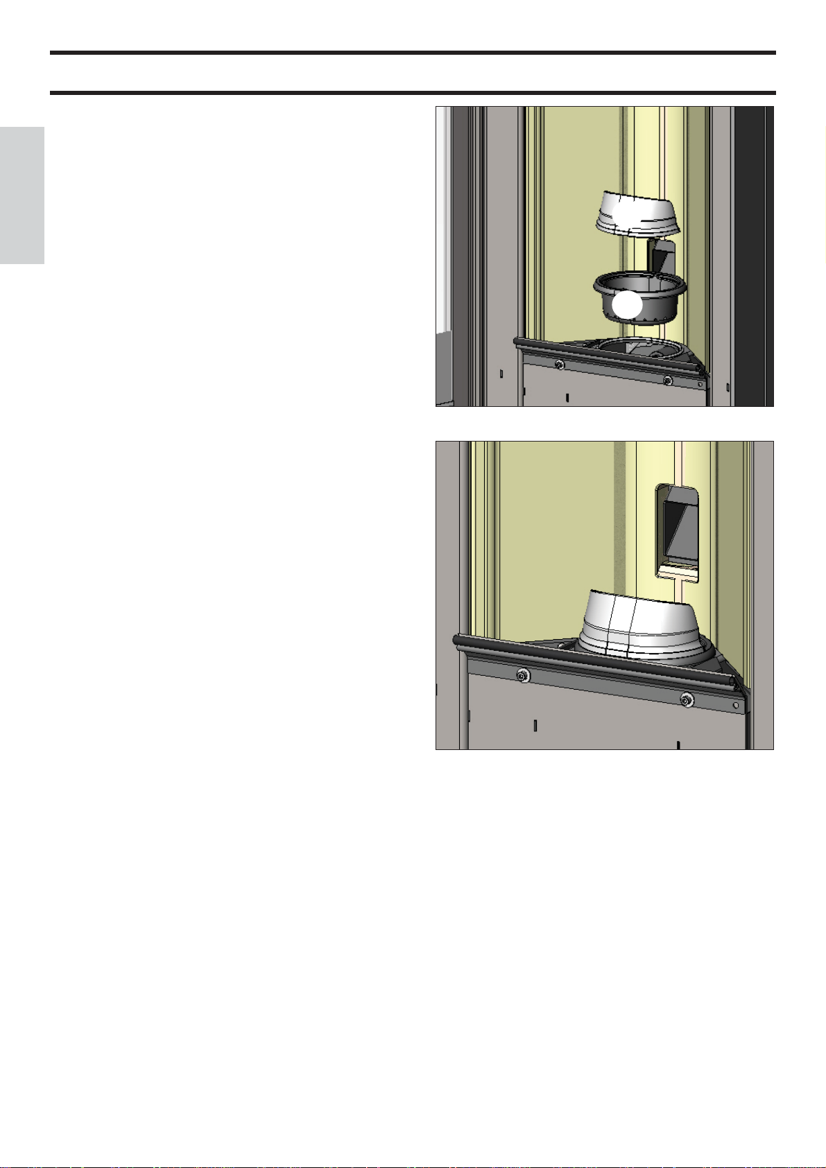
MAINTENANCE
SEASONAL MAINTENANCE
(implemented by the DEALER)
Consists of:
• Clean the stove internally and externally
• Thorough cleaning of the heat exchange piping inside the hot
air outlet grille located in the upper part of the front of the stove
• Carefully clean and remove dirt from the combustion chamber
and the relative compartment
ENGLISH
• Clean fans, verify mechanical and clamp loosening
• Clean smoke channel (replace seals on smoke exhaust pipe)
• Clean smoke duct especially if
• Clean/check the Synoptic Panel
• Visual check of power cables, connections and power cord.
• Clean the pellet hopper and check loosening of the feed screw gear motor assembly
• Check the small pressure-switch pipe, and replace when necessary
• Replace the door seal
• Functionality test: load the feed screw, ignite, let it run for 10
minutes and shutdown
If the stove is used very frequently, it is advisable to clean the
smoke channel and the fume duct every 3 months.
A
B
fi g. D
ATTENTION !!!
After implementing a normal cleaning procedure, INCORRECT coupling of the upper (A) (fi gura D) and lower
(B) (fi gura D) combustion chambers can compromise the
stove’s performance.
Before igniting the stove, make sure the combustion chambers are correctly paired as indicated in (fi g. E) without ash
or unburnt material present on the support perimeter.
N.B.
- Any unauthorised modifi cation is forbidden
- Use spare parts recommended by the manufacturer
- The use of counterfeit parts results in the guarantee becoming null and void
fi g. E
- 28 -

POSSIBLE TROUBLESHOOTING
In the event of problems the stove stops automatically and runs the shutdown process and the display shows text
regarding the motivation of the shutdown (see the various alarms below).
Never pull the plug during shutdown on account of malfunction.
Should it block, to restart the stove you will need to allow the turn-off procedure to take place (600 seconds with
audible signal), and then press the button
.
Do not turn the stove on again before checking the cause of the malfunction and CLEANING/ EMPTYING the crucible.
INDICATION OF POSSIBLE CAUSES OF MALFUNCTION INSTRUCTIONS AND SOLUTIONS:
1) Segnalazione: Signalling: Verifi c./extract.: (this trips if the smoke extraction speed sensor detects a fault)
Problem: Shutdown for smoke extraction speed fault detection
Actions: • Check smoke extractor function (revolution sensor connection) and board (DEALER).
• Check smoke channel for dirt
• Verify the electrical system and earthing system.
• Check eletronic circuit board (DEALER).
2) Signalling: Stop/Flame: (this trips if the thermocouple detects a smoke temperature lower than the value set, which it
interprets as the absence of fl ames)
Problem: Turns off due to drop in smoke temperature
Flame may fail for any of the following reasons:
- lack of pellets
- too many pellets have suffocated the fl ame, check pellet quality (DEALER)
- the maximum thermostat has intervened (rare, this only intervenes in the event of excessive smoke
temperature) (DEALER)
- The safety pressure switch comes on because of clogging/blockage of the smoke discharge pipe or
the fl ue (have it checked by a qualifi ed technician - chimney sweep)
- Activation of the safety thermostat of the tank. Check that around the stove there aren’t any objects
blocking the ventilation or whether the fans are broken or off, in which case call the DEALER.
3) Signalling: Block_FI/NO Start: (intervenes if a fl ame fails to appear within a maximum of 15 minutes, or if ignition
temperature is not reached).
• Check correct functioning of the pressure switch (CAT)
ENGLISH
Problem: Turns off due to incorrect smoke temperature during ignition
Distinguish either of the following cases:
Flame does NOT appear
Actions: • Check: - combustion chamber position and cleanliness;
• Check that there are pellets in the tank and the fi re box
• arrival of combustion air in the combustion chamber;
• if the heating element is working (DEALER);
• room temperature (if lower than 3°C use a fi relighter) and dampness.
Try to light with a fi relighter (see page 25).
Flames appear, but AF appears on the display after Ar
Actions: • Check: (only by the Dealer)
• if the thermocouple is working (DEALER);
• start-up temperature setting in the parameters (DEALER).
4) Signalling: Black Out: (not a defect of the stove).
Problem: Turns off due to lack of electricity
Actions: • Check electricity connection and drops in voltage.
5) Signalling: Fault/RC: (intervenes if the thermo coupling has failed or is disconnected).
Problem: Turns off due to thermo coupling failed or disconnected
Actions: • Check connection of thermo coupling to board: check function in cold test (DEALER).
- 29 -

POSSIBLE TROUBLESHOOTING
6) Signalling: smoke °C/high.
Problem: turns off due to exceeding maximum smoke temperature.
Actions: • Check the pellet type
• Check for anomalies with the smoke-extraction motor
• Check to see if there are any obstructions in the smoke channel
• Check correct installation
• Gear motor faulty (CAT)
7) Signalling: Check button (signals an anomaly on the emergency button)
Actions: • check maintenance status of the button and its board connection cable (DEALER).
ENGLISH
8) Signalling: “Battery check”
Problem: The insert does not stop but the error appears on the display.
Actions: • The buffer battery of the control board needs changing (DEALER).
Remember that this component is subject to regular wear and so it is not covered by the guarantee.
9) Signalling: ALARM - HIGH CURRENT: Activated when anomalous, excessive current absorption is detected on the
Actions: Check functioning (CAT): gear motor - Electrical connections and electronic board.
10) Signalling: ALARM - LOW CURRENT: Activated when anomalous, insuffi cient current absorption is detected on the
Actions: Check functioning (CAT): gear motor - pressure switch - tank thermostat - electrical connections and electro-
11) Problem: Remote control not working
Actions: • Move closer to the stove
• check the battery and if necessary, replace it.
• Synchronisation with automatic search on activation: when you put the batteries into the radio control a
• Synchronisation with automatic search and manual activation - it is possible to launch an automatic search
- Go close to the product’s antenna and make sure it is connected to the electricity supply.
- With the display switched off (standby) hold the 0/I key down for 10”.
- After 10” a “NETWORK SEARCH” message appears on the display, then release the o/I key, as this means
- Automatic tuning of the radio channel will occur within a few seconds.
12) Problem: During ignition, the differential switch trips (DEALER):
Actions: • Check the condition of the ignition coil, the electrical system, and the electrical components.
13) Problem: Outgoing air not hot:
Actions: • Check that the fan is working.
gear motor..
gear motor.
nic board
radio channel search phase will start up automatically, and it will subsequently connect to the product detected. So that this occurs correctly, make sure to switch the product on before inserting the batteries in the
radio control, and stay in the vicinity of the antenna in order to achieve radio coverage with certainty.
for a product manually, simply carry out the following operations after having already put the batteries into
the radio control:
that the automatic search has been activated.
NOTE 1
All signals/warnings remain shown until you intervene on the remote control, by pressing the button
Do not use the insert before having eliminated the problem.
NOTE 2
Once 1000 kg of pellets have been consumed or some other value set by the CAT during the fi rst ignition, the display
fl ashes a message that reads “maintenance”.
The stove works, but you must call the Dealer out to perform extraordinary maintenance.
NOTE 3
solid-fue due to the quality of pellets or particularly critical installation, the stove becomes clogged earlier, the message
“CALL SERVICE” will appear. Proceed as per “Mainten.” instructions.
N.B.:
The combustion chambers and smoke ducts connected to the solid-fuel appliances must be cleaned once a year (check
if your country has specifi c legislation covering this).
Failure to regularly check and clean increases the likelihood of a fi re in the chimney pot.
.
IMPORTANT!!!
In the case of a fi re in the stove, in the fl ue or in the chimney, proceed as follows:
- Disconnect the power supply
- Use a carbon dioxide (CO2) extinguisher
- Call the fi re brigade
DO NOT ATTEMPT TO PUT THE FIRE OUT WITH WATER!
After the event, have the appliance checked by an authorised Service Centre and have an authorised technician check the fl ue.
- 30 -
 Loading...